EP1671385B1 - Process for solid oxide fuel cell manufacture - Google Patents
Process for solid oxide fuel cell manufacture Download PDFInfo
- Publication number
- EP1671385B1 EP1671385B1 EP04783704A EP04783704A EP1671385B1 EP 1671385 B1 EP1671385 B1 EP 1671385B1 EP 04783704 A EP04783704 A EP 04783704A EP 04783704 A EP04783704 A EP 04783704A EP 1671385 B1 EP1671385 B1 EP 1671385B1
- Authority
- EP
- European Patent Office
- Prior art keywords
- layer
- electrolyte
- thickness
- electrode layer
- forming
- Prior art date
- Legal status (The legal status is an assumption and is not a legal conclusion. Google has not performed a legal analysis and makes no representation as to the accuracy of the status listed.)
- Expired - Lifetime
Links
- 238000000034 method Methods 0.000 title claims description 88
- 239000000446 fuel Substances 0.000 title claims description 43
- 239000007787 solid Substances 0.000 title claims description 33
- 238000004519 manufacturing process Methods 0.000 title claims description 12
- 239000003792 electrolyte Substances 0.000 claims description 65
- 238000010438 heat treatment Methods 0.000 claims description 24
- 239000002131 composite material Substances 0.000 claims description 23
- 239000000463 material Substances 0.000 claims description 23
- 239000011230 binding agent Substances 0.000 claims description 17
- 239000002002 slurry Substances 0.000 claims description 17
- 238000010304 firing Methods 0.000 claims description 15
- 238000000151 deposition Methods 0.000 claims description 12
- 239000002270 dispersing agent Substances 0.000 claims description 11
- 238000001035 drying Methods 0.000 claims description 11
- 239000002904 solvent Substances 0.000 claims description 11
- 239000004014 plasticizer Substances 0.000 claims description 10
- 229910052712 strontium Inorganic materials 0.000 claims description 10
- CIOAGBVUUVVLOB-UHFFFAOYSA-N strontium atom Chemical compound [Sr] CIOAGBVUUVVLOB-UHFFFAOYSA-N 0.000 claims description 9
- 229910000420 cerium oxide Inorganic materials 0.000 claims description 8
- BMMGVYCKOGBVEV-UHFFFAOYSA-N oxo(oxoceriooxy)cerium Chemical compound [Ce]=O.O=[Ce]=O BMMGVYCKOGBVEV-UHFFFAOYSA-N 0.000 claims description 8
- 239000000919 ceramic Substances 0.000 claims description 7
- 239000004020 conductor Substances 0.000 claims description 7
- 239000002001 electrolyte material Substances 0.000 claims description 7
- 229910052746 lanthanum Inorganic materials 0.000 claims description 7
- FZLIPJUXYLNCLC-UHFFFAOYSA-N lanthanum atom Chemical compound [La] FZLIPJUXYLNCLC-UHFFFAOYSA-N 0.000 claims description 7
- 239000000843 powder Substances 0.000 claims description 7
- 238000007650 screen-printing Methods 0.000 claims description 7
- 239000000758 substrate Substances 0.000 claims description 5
- 229910001938 gadolinium oxide Inorganic materials 0.000 claims description 4
- 229940075613 gadolinium oxide Drugs 0.000 claims description 4
- 230000005855 radiation Effects 0.000 claims description 4
- 238000005245 sintering Methods 0.000 claims description 4
- OKTJSMMVPCPJKN-UHFFFAOYSA-N Carbon Chemical group [C] OKTJSMMVPCPJKN-UHFFFAOYSA-N 0.000 claims description 3
- 229910000480 nickel oxide Inorganic materials 0.000 claims description 3
- LNTHITQWFMADLM-UHFFFAOYSA-N gallic acid Chemical compound OC(=O)C1=CC(O)=C(O)C(O)=C1 LNTHITQWFMADLM-UHFFFAOYSA-N 0.000 claims description 2
- RIAXXCZORHQTQD-UHFFFAOYSA-N lanthanum magnesium Chemical compound [Mg].[La] RIAXXCZORHQTQD-UHFFFAOYSA-N 0.000 claims description 2
- 239000007800 oxidant agent Substances 0.000 claims description 2
- 230000001590 oxidative effect Effects 0.000 claims description 2
- 239000011224 oxide ceramic Substances 0.000 claims description 2
- 229910052761 rare earth metal Inorganic materials 0.000 claims description 2
- 150000002910 rare earth metals Chemical class 0.000 claims description 2
- 239000007784 solid electrolyte Substances 0.000 claims description 2
- 238000010345 tape casting Methods 0.000 claims description 2
- PXHVJJICTQNCMI-UHFFFAOYSA-N Nickel Chemical compound [Ni] PXHVJJICTQNCMI-UHFFFAOYSA-N 0.000 claims 6
- RVTZCBVAJQQJTK-UHFFFAOYSA-N oxygen(2-);zirconium(4+) Chemical compound [O-2].[O-2].[Zr+4] RVTZCBVAJQQJTK-UHFFFAOYSA-N 0.000 claims 4
- 229910001928 zirconium oxide Inorganic materials 0.000 claims 4
- 239000010941 cobalt Substances 0.000 claims 2
- GUTLYIVDDKVIGB-UHFFFAOYSA-N cobalt atom Chemical compound [Co] GUTLYIVDDKVIGB-UHFFFAOYSA-N 0.000 claims 2
- 239000011262 electrochemically active material Substances 0.000 claims 2
- CMIHHWBVHJVIGI-UHFFFAOYSA-N gadolinium(iii) oxide Chemical compound [O-2].[O-2].[O-2].[Gd+3].[Gd+3] CMIHHWBVHJVIGI-UHFFFAOYSA-N 0.000 claims 2
- 229910017052 cobalt Inorganic materials 0.000 claims 1
- 229910000428 cobalt oxide Inorganic materials 0.000 claims 1
- 229910052759 nickel Inorganic materials 0.000 claims 1
- 229910001954 samarium oxide Inorganic materials 0.000 claims 1
- 229940075630 samarium oxide Drugs 0.000 claims 1
- FKTOIHSPIPYAPE-UHFFFAOYSA-N samarium(iii) oxide Chemical compound [O-2].[O-2].[O-2].[Sm+3].[Sm+3] FKTOIHSPIPYAPE-UHFFFAOYSA-N 0.000 claims 1
- 238000009966 trimming Methods 0.000 claims 1
- 229910001233 yttria-stabilized zirconia Inorganic materials 0.000 description 26
- 239000002245 particle Substances 0.000 description 9
- 230000005611 electricity Effects 0.000 description 7
- 239000007789 gas Substances 0.000 description 6
- 238000010923 batch production Methods 0.000 description 5
- 238000007639 printing Methods 0.000 description 5
- QVGXLLKOCUKJST-UHFFFAOYSA-N atomic oxygen Chemical compound [O] QVGXLLKOCUKJST-UHFFFAOYSA-N 0.000 description 4
- 238000003487 electrochemical reaction Methods 0.000 description 4
- 239000001301 oxygen Substances 0.000 description 4
- 229910052760 oxygen Inorganic materials 0.000 description 4
- LFQSCWFLJHTTHZ-UHFFFAOYSA-N Ethanol Chemical compound CCO LFQSCWFLJHTTHZ-UHFFFAOYSA-N 0.000 description 3
- UFHFLCQGNIYNRP-UHFFFAOYSA-N Hydrogen Chemical compound [H][H] UFHFLCQGNIYNRP-UHFFFAOYSA-N 0.000 description 3
- OKKJLVBELUTLKV-UHFFFAOYSA-N Methanol Chemical compound OC OKKJLVBELUTLKV-UHFFFAOYSA-N 0.000 description 3
- YXFVVABEGXRONW-UHFFFAOYSA-N Toluene Chemical compound CC1=CC=CC=C1 YXFVVABEGXRONW-UHFFFAOYSA-N 0.000 description 3
- 239000003054 catalyst Substances 0.000 description 3
- 230000001413 cellular effect Effects 0.000 description 3
- 238000009826 distribution Methods 0.000 description 3
- 239000001257 hydrogen Substances 0.000 description 3
- 229910052739 hydrogen Inorganic materials 0.000 description 3
- 239000010416 ion conductor Substances 0.000 description 3
- KFZMGEQAYNKOFK-UHFFFAOYSA-N Isopropanol Chemical compound CC(C)O KFZMGEQAYNKOFK-UHFFFAOYSA-N 0.000 description 2
- NBIIXXVUZAFLBC-UHFFFAOYSA-N Phosphoric acid Chemical compound OP(O)(O)=O NBIIXXVUZAFLBC-UHFFFAOYSA-N 0.000 description 2
- 239000012298 atmosphere Substances 0.000 description 2
- 238000010924 continuous production Methods 0.000 description 2
- 239000007772 electrode material Substances 0.000 description 2
- 239000002803 fossil fuel Substances 0.000 description 2
- 238000001000 micrograph Methods 0.000 description 2
- XLYOFNOQVPJJNP-UHFFFAOYSA-N water Substances O XLYOFNOQVPJJNP-UHFFFAOYSA-N 0.000 description 2
- BVKZGUZCCUSVTD-UHFFFAOYSA-L Carbonate Chemical compound [O-]C([O-])=O BVKZGUZCCUSVTD-UHFFFAOYSA-L 0.000 description 1
- ZOKXTWBITQBERF-UHFFFAOYSA-N Molybdenum Chemical compound [Mo] ZOKXTWBITQBERF-UHFFFAOYSA-N 0.000 description 1
- 229910018487 Ni—Cr Inorganic materials 0.000 description 1
- 239000004372 Polyvinyl alcohol Substances 0.000 description 1
- RHLFGQZLNLRASV-UHFFFAOYSA-N [O-2].[Sm+3].[Ni+2] Chemical compound [O-2].[Sm+3].[Ni+2] RHLFGQZLNLRASV-UHFFFAOYSA-N 0.000 description 1
- 229910000147 aluminium phosphate Inorganic materials 0.000 description 1
- 238000005266 casting Methods 0.000 description 1
- 239000003795 chemical substances by application Substances 0.000 description 1
- VNNRSPGTAMTISX-UHFFFAOYSA-N chromium nickel Chemical compound [Cr].[Ni] VNNRSPGTAMTISX-UHFFFAOYSA-N 0.000 description 1
- NFYLSJDPENHSBT-UHFFFAOYSA-N chromium(3+);lanthanum(3+);oxygen(2-) Chemical compound [O-2].[O-2].[O-2].[Cr+3].[La+3] NFYLSJDPENHSBT-UHFFFAOYSA-N 0.000 description 1
- 238000010344 co-firing Methods 0.000 description 1
- 239000011248 coating agent Substances 0.000 description 1
- 238000000576 coating method Methods 0.000 description 1
- ZXIMJENGZNNPHH-UHFFFAOYSA-N cobalt(2+) gadolinium(3+) oxygen(2-) Chemical compound [O-2].[Gd+3].[Co+2] ZXIMJENGZNNPHH-UHFFFAOYSA-N 0.000 description 1
- 230000008878 coupling Effects 0.000 description 1
- 238000010168 coupling process Methods 0.000 description 1
- 238000005859 coupling reaction Methods 0.000 description 1
- 238000005336 cracking Methods 0.000 description 1
- 230000032798 delamination Effects 0.000 description 1
- 230000000694 effects Effects 0.000 description 1
- 238000001652 electrophoretic deposition Methods 0.000 description 1
- 235000021323 fish oil Nutrition 0.000 description 1
- HZLLPQBYQASDPK-UHFFFAOYSA-N gadolinium(3+) nickel(2+) oxygen(2-) Chemical compound [O-2].[Gd+3].[Ni+2] HZLLPQBYQASDPK-UHFFFAOYSA-N 0.000 description 1
- 238000001764 infiltration Methods 0.000 description 1
- 230000008595 infiltration Effects 0.000 description 1
- 238000007641 inkjet printing Methods 0.000 description 1
- 229910000473 manganese(VI) oxide Inorganic materials 0.000 description 1
- 239000012528 membrane Substances 0.000 description 1
- 238000002044 microwave spectrum Methods 0.000 description 1
- 239000000203 mixture Substances 0.000 description 1
- 229910052750 molybdenum Inorganic materials 0.000 description 1
- 239000011733 molybdenum Substances 0.000 description 1
- QVHBYRDRZVIXKD-UHFFFAOYSA-N molybdenum(4+) silicate Chemical compound [Si]([O-])([O-])([O-])[O-].[Mo+4] QVHBYRDRZVIXKD-UHFFFAOYSA-N 0.000 description 1
- 230000003287 optical effect Effects 0.000 description 1
- 239000011368 organic material Substances 0.000 description 1
- 229910052574 oxide ceramic Inorganic materials 0.000 description 1
- GNRSAWUEBMWBQH-UHFFFAOYSA-N oxonickel Chemical compound [Ni]=O GNRSAWUEBMWBQH-UHFFFAOYSA-N 0.000 description 1
- 229920002037 poly(vinyl butyral) polymer Polymers 0.000 description 1
- 229920002451 polyvinyl alcohol Polymers 0.000 description 1
- 238000003825 pressing Methods 0.000 description 1
- 238000000926 separation method Methods 0.000 description 1
- HBMJWWWQQXIZIP-UHFFFAOYSA-N silicon carbide Chemical compound [Si+]#[C-] HBMJWWWQQXIZIP-UHFFFAOYSA-N 0.000 description 1
- 229910010271 silicon carbide Inorganic materials 0.000 description 1
- 238000005507 spraying Methods 0.000 description 1
- 238000006467 substitution reaction Methods 0.000 description 1
Images


Classifications
-
- H—ELECTRICITY
- H01—ELECTRIC ELEMENTS
- H01M—PROCESSES OR MEANS, e.g. BATTERIES, FOR THE DIRECT CONVERSION OF CHEMICAL ENERGY INTO ELECTRICAL ENERGY
- H01M4/00—Electrodes
- H01M4/86—Inert electrodes with catalytic activity, e.g. for fuel cells
- H01M4/90—Selection of catalytic material
- H01M4/9016—Oxides, hydroxides or oxygenated metallic salts
- H01M4/9025—Oxides specially used in fuel cell operating at high temperature, e.g. SOFC
- H01M4/9033—Complex oxides, optionally doped, of the type M1MeO3, M1 being an alkaline earth metal or a rare earth, Me being a metal, e.g. perovskites
-
- H—ELECTRICITY
- H01—ELECTRIC ELEMENTS
- H01M—PROCESSES OR MEANS, e.g. BATTERIES, FOR THE DIRECT CONVERSION OF CHEMICAL ENERGY INTO ELECTRICAL ENERGY
- H01M8/00—Fuel cells; Manufacture thereof
-
- H—ELECTRICITY
- H01—ELECTRIC ELEMENTS
- H01M—PROCESSES OR MEANS, e.g. BATTERIES, FOR THE DIRECT CONVERSION OF CHEMICAL ENERGY INTO ELECTRICAL ENERGY
- H01M4/00—Electrodes
- H01M4/86—Inert electrodes with catalytic activity, e.g. for fuel cells
-
- H—ELECTRICITY
- H01—ELECTRIC ELEMENTS
- H01M—PROCESSES OR MEANS, e.g. BATTERIES, FOR THE DIRECT CONVERSION OF CHEMICAL ENERGY INTO ELECTRICAL ENERGY
- H01M4/00—Electrodes
- H01M4/86—Inert electrodes with catalytic activity, e.g. for fuel cells
- H01M4/8605—Porous electrodes
- H01M4/8621—Porous electrodes containing only metallic or ceramic material, e.g. made by sintering or sputtering
-
- H—ELECTRICITY
- H01—ELECTRIC ELEMENTS
- H01M—PROCESSES OR MEANS, e.g. BATTERIES, FOR THE DIRECT CONVERSION OF CHEMICAL ENERGY INTO ELECTRICAL ENERGY
- H01M4/00—Electrodes
- H01M4/86—Inert electrodes with catalytic activity, e.g. for fuel cells
- H01M4/8647—Inert electrodes with catalytic activity, e.g. for fuel cells consisting of more than one material, e.g. consisting of composites
- H01M4/8657—Inert electrodes with catalytic activity, e.g. for fuel cells consisting of more than one material, e.g. consisting of composites layered
-
- H—ELECTRICITY
- H01—ELECTRIC ELEMENTS
- H01M—PROCESSES OR MEANS, e.g. BATTERIES, FOR THE DIRECT CONVERSION OF CHEMICAL ENERGY INTO ELECTRICAL ENERGY
- H01M4/00—Electrodes
- H01M4/86—Inert electrodes with catalytic activity, e.g. for fuel cells
- H01M4/88—Processes of manufacture
- H01M4/8878—Treatment steps after deposition of the catalytic active composition or after shaping of the electrode being free-standing body
- H01M4/8882—Heat treatment, e.g. drying, baking
- H01M4/8885—Sintering or firing
-
- H—ELECTRICITY
- H01—ELECTRIC ELEMENTS
- H01M—PROCESSES OR MEANS, e.g. BATTERIES, FOR THE DIRECT CONVERSION OF CHEMICAL ENERGY INTO ELECTRICAL ENERGY
- H01M4/00—Electrodes
- H01M4/86—Inert electrodes with catalytic activity, e.g. for fuel cells
- H01M4/90—Selection of catalytic material
- H01M4/9016—Oxides, hydroxides or oxygenated metallic salts
-
- H—ELECTRICITY
- H01—ELECTRIC ELEMENTS
- H01M—PROCESSES OR MEANS, e.g. BATTERIES, FOR THE DIRECT CONVERSION OF CHEMICAL ENERGY INTO ELECTRICAL ENERGY
- H01M4/00—Electrodes
- H01M4/86—Inert electrodes with catalytic activity, e.g. for fuel cells
- H01M4/90—Selection of catalytic material
- H01M4/9041—Metals or alloys
- H01M4/905—Metals or alloys specially used in fuel cell operating at high temperature, e.g. SOFC
- H01M4/9066—Metals or alloys specially used in fuel cell operating at high temperature, e.g. SOFC of metal-ceramic composites or mixtures, e.g. cermets
-
- H—ELECTRICITY
- H01—ELECTRIC ELEMENTS
- H01M—PROCESSES OR MEANS, e.g. BATTERIES, FOR THE DIRECT CONVERSION OF CHEMICAL ENERGY INTO ELECTRICAL ENERGY
- H01M8/00—Fuel cells; Manufacture thereof
- H01M8/10—Fuel cells with solid electrolytes
- H01M8/12—Fuel cells with solid electrolytes operating at high temperature, e.g. with stabilised ZrO2 electrolyte
- H01M8/1213—Fuel cells with solid electrolytes operating at high temperature, e.g. with stabilised ZrO2 electrolyte characterised by the electrode/electrolyte combination or the supporting material
-
- H—ELECTRICITY
- H01—ELECTRIC ELEMENTS
- H01M—PROCESSES OR MEANS, e.g. BATTERIES, FOR THE DIRECT CONVERSION OF CHEMICAL ENERGY INTO ELECTRICAL ENERGY
- H01M8/00—Fuel cells; Manufacture thereof
- H01M8/10—Fuel cells with solid electrolytes
- H01M8/12—Fuel cells with solid electrolytes operating at high temperature, e.g. with stabilised ZrO2 electrolyte
- H01M8/124—Fuel cells with solid electrolytes operating at high temperature, e.g. with stabilised ZrO2 electrolyte characterised by the process of manufacturing or by the material of the electrolyte
- H01M8/1246—Fuel cells with solid electrolytes operating at high temperature, e.g. with stabilised ZrO2 electrolyte characterised by the process of manufacturing or by the material of the electrolyte the electrolyte consisting of oxides
-
- H—ELECTRICITY
- H01—ELECTRIC ELEMENTS
- H01M—PROCESSES OR MEANS, e.g. BATTERIES, FOR THE DIRECT CONVERSION OF CHEMICAL ENERGY INTO ELECTRICAL ENERGY
- H01M2300/00—Electrolytes
- H01M2300/0017—Non-aqueous electrolytes
- H01M2300/0065—Solid electrolytes
- H01M2300/0068—Solid electrolytes inorganic
- H01M2300/0071—Oxides
- H01M2300/0074—Ion conductive at high temperature
- H01M2300/0077—Ion conductive at high temperature based on zirconium oxide
-
- H—ELECTRICITY
- H01—ELECTRIC ELEMENTS
- H01M—PROCESSES OR MEANS, e.g. BATTERIES, FOR THE DIRECT CONVERSION OF CHEMICAL ENERGY INTO ELECTRICAL ENERGY
- H01M2300/00—Electrolytes
- H01M2300/0088—Composites
- H01M2300/0094—Composites in the form of layered products, e.g. coatings
-
- Y—GENERAL TAGGING OF NEW TECHNOLOGICAL DEVELOPMENTS; GENERAL TAGGING OF CROSS-SECTIONAL TECHNOLOGIES SPANNING OVER SEVERAL SECTIONS OF THE IPC; TECHNICAL SUBJECTS COVERED BY FORMER USPC CROSS-REFERENCE ART COLLECTIONS [XRACs] AND DIGESTS
- Y02—TECHNOLOGIES OR APPLICATIONS FOR MITIGATION OR ADAPTATION AGAINST CLIMATE CHANGE
- Y02E—REDUCTION OF GREENHOUSE GAS [GHG] EMISSIONS, RELATED TO ENERGY GENERATION, TRANSMISSION OR DISTRIBUTION
- Y02E60/00—Enabling technologies; Technologies with a potential or indirect contribution to GHG emissions mitigation
- Y02E60/30—Hydrogen technology
- Y02E60/50—Fuel cells
-
- Y—GENERAL TAGGING OF NEW TECHNOLOGICAL DEVELOPMENTS; GENERAL TAGGING OF CROSS-SECTIONAL TECHNOLOGIES SPANNING OVER SEVERAL SECTIONS OF THE IPC; TECHNICAL SUBJECTS COVERED BY FORMER USPC CROSS-REFERENCE ART COLLECTIONS [XRACs] AND DIGESTS
- Y02—TECHNOLOGIES OR APPLICATIONS FOR MITIGATION OR ADAPTATION AGAINST CLIMATE CHANGE
- Y02P—CLIMATE CHANGE MITIGATION TECHNOLOGIES IN THE PRODUCTION OR PROCESSING OF GOODS
- Y02P70/00—Climate change mitigation technologies in the production process for final industrial or consumer products
- Y02P70/50—Manufacturing or production processes characterised by the final manufactured product
Definitions
- a fuel cell is a device or system that generates electricity by an electrochemical reaction in which oxygen and hydrogen combine to form water.
- An electrolyte in the cell carries charged particles across a cathode to an anode. Catalysts are often employed to accelerate and improve the efficiency of the electrochemical reaction.
- Fuel cell devices are a viable source of alternative energy. These devices are generally more efficient and produce less pollution than conventional sources of power.
- the electricity produced by fuel cells can be used to power, for example, aeronautical systems, computer devices, automotive systems and cellular devices.
- fuel cells are classified by the type of electrolyte used. Fuel cell devices also feature different materials depending on an application or specific power requirements. The variety of fuel cells includes, for example, phosphoric acid, proton exchange membrane, molten carbonate, alkaline and solid oxide devices.
- SOFC solid oxide fuel cell
- An SOFC comprises a dense electrolyte that is positioned between porous electrodes, namely, the cathode and anode.
- the dense electrolyte can be a solid oxygen-ion conductor such as yttria-stabilized zirconia (YSZ).
- the cathode and anode can be ceramic composites such as strontium doped lanthanum manganite-YSZ and nickel-YSZ oxide, respectively.
- SOFC devices can also be assembled into a planar stack in which several cells are arranged with interconnects separating each cell.
- SOFC devices are manufactured by batch processes. Batch processes are used to slowly heat and fire the fuel cell structure to prevent the electrolyte and electrodes from distorting.
- a standard batch process can uniformly heat and fire an SOFC at a thermal rate of about 1 °C per minute. This rate can require several hours to sinter the electrolyte and electrode structures.
- the process can also require multiple thermal cycles to heat and cool the cell during fabrication.
- manufacturing a fuel cell by such processes is entirely inefficient and expensive. With the growing demand for fuel cells, there is a specific need for an efficient fabrication process that is inexpensive and does not require multiple thermal cycles.
- U.S. Patent Application Publication No. 2003/082434 discloses solid oxide fuel cells made by coating a slurry of an electrolyte having a limited amount of organic material onto a carrier tape, depositing a one or two layer electrode material on the tape sufficient to support the electrolyte layer, removing the tape, screen printing a second electrode layer on the exposed surface of the electrolyte layer, and firing the layers at a temperature of 1100-1300°C.
- U.S. Patent No. 4,799,936 discloses a solid oxide fuel cell which is formed in the green state with a binder and then a combination of microwave and conventional heating is employed to first remove the binder at a lower temperature and then sinter the oxides at a higher temperature to form the fuel cell, which heating technique not only reduces the time and power requirement but also eliminates large temperature gradients within the oxide material and reduces the attendant problems of internal cracking, separation of components, blistering and delamination.
- U.S. Patent No. 5,143,801 discloses an air electrode material for a solid oxide fuel cell comprising Y 1-a Q a MnO 3 , where "Q" is selected from the group consisting of Ca and Sr or mixtures thereof and "a" is from 0.1 to 0.8.
- the solid oxide fuel cell is described as being fabricated by type casting separate tapes for each of the air electrode, fuel electrode, electrolyte and current interconnection, which are then combined into a sandwich and sintered in air in a number of steps.
- the present invention is directed to a method for manufacturing a solid oxide fuel cell, the method comprising forming a first electrode layer, which before firing has a thickness of 0.5 to 2.0 mm, the first electrode layer having a surface; forming an electrolyte layer by screen printing a powder slurry on the surface of the first electrode layer; forming a second electrode layer on a surface of the electrolyte layer, wherein the layers comprise a multilayer electrochemical structure; thermally processing the multilayer structure in a single thermal cycle, which thermal cycle comprises: heating the multilayer structure in a first portion of the single thermal cycle to a temperature and for a time to remove moisture; heating the multilayer structure in a second portion of the single thermal cycle to a temperature and for a time to remove binder; heating the multilayer structure in a third portion of the single thermal cycle to a temperature and for a time to remove carbon residue; and firing the multilayer structure in a fourth portion of the single thermal cycle at a temperature and for a time to sinter each layer and to form a solid
- the present invention is also directed to a method for manufacturing a solid oxide fuel cell stack, the method comprising performing the method described above, disposing an interconnect onto a surface of the multilayer electrochemical structure; and repeating the method described above, wherein the interconnect substantially separates the multilayer structures.
- the present invention provides a method for conveniently manufacturing a solid oxide fuel cell (SOFC) at a cost that is less than five-hundred dollars per kilowatt of electricity.
- the method comprises forming an electrode layer and depositing an electrolyte material on the surface of the electrode.
- the formed structure is an electrode-electrolyte bi-layer.
- a second electrode is deposited onto this bi-layer to form a multilayer fuel cell structure comprising an electrolyte positioned between two electrodes.
- This multilayer structure is then heated and fired in a single thermal cycle to remove any binder materials and sinter, respectively, the fuel cell.
- This thermal cycle can be performed in a furnace having one or more chambers.
- the chamber(s) preferably contains a variable or multiple frequency microwave source for heating the cell and removing binder materials in the electrolyte and electrode structures.
- the chamber(s) also preferably includes a convection and/or radiation source for sintering the fuel cell.
- the method of the invention harmonizes and minimizes the deviation among the thermophysical properties of the electrolyte and electrode structures. This harmonization reduces and minimizes the temperature gradient within the cell such that the structure can be uniformly heated and fired during the thermal cycle.
- the multilayer structure is also unlikely to distort and fracture by minimizing the temperature gradient in the cell.
- a multilayer fuel cell can also be manufactured by the present method in an order of magnitude less time than standard processes.
- the method of the invention can be employed to fabricate an SOFC stack in which several cells are arranged with interconnects separating each cell.
- These fuel cell devices could be used to power, for example, aeronautical systems, computer devices, automotive systems and cellular devices.
- An SOFC manufactured by the disclosed method generally operates in a temperature range from about 700 to 1100 °C.
- the SOFC comprises a dense electrolyte that is positioned between porous electrodes, namely, the cathode and anode.
- the dense electrolyte can be a solid oxygen-ion conductor such as yttria-stabilized zirconia (YSZ).
- YSZ yttria-stabilized zirconia
- the cathode and anode can be ceramic composites such as strontium doped lanthanum manganite-YSZ and nickel-YSZ oxide, respectively.
- the method of the invention comprises forming an electrode by controllably distributing phases and particles sizes.
- the electrode can be an individual or multiple layer porous structure that is "green” or unfired.
- the electrode is also dried to have a thickness in the range of about 0.5 to 2.0 mm.
- a dense electrolyte is then deposited by screen printing onto the electrode surface as an individual or multiple solid layer having a dried thickness in the range of about 5 to 1000 ⁇ m.
- a second electrode is deposited on this bi-layer structure.
- the second electrode can also be an individual or multiple layer porous structure having a dried thickness in the range of about 50 to 150 ⁇ m.
- Each of the above electrode layers are formed by suitable deposition techniques such as, for example, screen printing, vacuum infiltration, electrophoretic deposition, ink jet printing, cold pressing, tape casting or spraying.
- the formed multilayer structure is then be heated and fired in one thermal cycle. This cycle can be performed at a thermal rate of about 10 °C per minute.
- the present invention provides a method for fabricating a solid oxide fuel cell (SOFC) in a single thermal cycle.
- This cycle can be performed as a batch or continuous process.
- An SOFC can be conveniently manufactured according to the invention at a cost that is less than five-hundred dollars per kilowatt of electricity.
- the manufactured SOFC also operates in a temperature range from about 700 to 1100 °C.
- the method of the invention can fabricate an SOFC stack in which several cells are arranged with interconnects separating each cell.
- Fuel cell devices manufactured by the disclosed method could be used to power, for example, aeronautical systems, computer devices, automotive systems and cellular devices.
- Fuel cells offer an environmentally clean and versatile power source for efficiently converting fossil fuels into electricity and heat.
- Figure 1 is a representation of an SOFC 10 comprising a dense electrolyte 12 that is positioned between porous electrodes, namely, the cathode 18 and anode 16.
- the dense electrolyte can be a solid oxygen-ion conductor such as yttria-stabilized zirconia (YSZ).
- the cathode and anode can be ceramic composites such as strontium doped lanthanum manganite-YSZ and nickel-YSZ oxide, respectively.
- the fuel cell generates electricity by an electrochemical reaction in which oxygen and hydrogen combine to form water.
- the electrodes reduce oxygen and oxidize hydrogen to yield a voltage 14.
- the electrodes can also comprises a catalyst such as nickel oxide. This catalyst can accelerate and improve the efficiency of the electrochemical reaction.
- Figure 2 is an SOFC stack 20 in which several cells are arranged with interconnects separating each cell.
- a single fuel cell in the planar stack comprises an electrolyte 25 that is positioned between a cathode 26 and anode 24.
- the interconnect could be a plate 22 or separator 28 that guides fuel and oxidant flows through the stack.
- These interconnects are commonly composites such as, for example, lanthanum chromite.
- the method of the invention comprises forming a first electrode layer. This can be done by controllably distributing phases and particles sizes to provide a thermophysically consistent layer having, for example, a uniform microstructure, elasticity and/or a coefficient of thermal expansion.
- Consistency among these properties prevents the electrode from distorting and fracturing in a thermal cycle.
- the method also harmonizes and minimizes the deviations among the thermophysical properties of the electrolyte and electrode layers. This harmonization reduces and minimizes the temperature gradient of the cell during the thermal cycle such that the structure can be uniformly heated and fired in an efficient manner.
- the electrode is preferably a porous anode such as shown in Figures 1 and 2 .
- the porous anode can also be an individual or multiple layer composite such as, for example, nickel-YSZ oxide, nickel-gadolinium oxide doped cerium oxide, nickel-samarium oxide doped cerium oxide, cobalt-YSZ oxide or cobalt-gadolinium oxide doped cerium oxide.
- the composite electrode is deposited as a green layer(s) having a thickness in the range of 0.5 to 2.0 mm.
- This electrode thickness acts as a mechanical support for the fuel cell.
- the thickness can depend on the tape cast layers preferably used to form the electrode. These layers can also be cast with varying porosities to control gas transport phenomena.
- tape cast layers are formed by depositing a powder slurry onto a substrate having a release material.
- the slurry can comprise binder, dispersant, solvent, plasticizer and composite solids.
- the binder for example, can be polyvinyl alcohol or polyvinyl butyral.
- a common solvent could include ethanol, toluene, methanol or isopropanol.
- the dispersant or dispersing "agent" can include fish oil. These materials are milled and sieved to remove soft agglomerates.
- a hopper aids the flow of powder slurry onto the substrate and a "doctor blade" uniformly distributes the slurry to cast the layer. This layer is then peeled from the substrate and trimmed for the electrode.
- the flowchart of Figure 3 shows a tape cast layer provided in step 40.
- the layer is dried by a suitable technique during step 42 in a temperature range from about 100 to 400 °C.
- This temperature range preferably evaporates materials in the cast layer such as dispersant, solvent and plasticizer to form the porous electrode.
- the temperature range can also vary depending on the volatility of these materials.
- the thickness of the electrode can then be measured in step 44 by a convenient technique such as, for example, an optical or scanning electron microscope.
- Additional tape cast layers can be deposited onto the electrode in step 45 and dried individually until a thickness in the range of 0.5 to 2.0 mm is measured. As described above, these additional layers can be cast with varying porosities to control gas transport phenomena and improve the efficiency of the electrode. It is preferable for the electrodes to be less porous near the electrolyte and increase in porosity through to their exterior surfaces.
- the formed individual or multiple layer electrode structure of step 46 is then prepared to be processed further according to the invention.
- FIG 4 shows a flowchart in which a dense electrolyte is formed on an electrode layer(s) prepared by the method of the invention.
- This electrolyte can be an individual or multiple layer solid conductor such as shown in Figures 1 and 2 .
- solid conductor materials include YSZ, ceria-gadolinium oxide, strontium, magnesium lanthanum gallate or a rare earth metal doped cerium oxide.
- An YSZ conductor operates efficiently in a temperature range from about 700 to 1100 °C, although this range could vary for different electrolyte solids.
- the electrolyte layer(s) are screen printed in step 50 onto the electrode surface as a powder slurry. Screen printing controls the distribution of phases and particle sizes to provide a consistent thermophysical structure.
- the deposited electrolyte preferably has a thickness in a range of about 5 to 1000 ⁇ m. This thickness depends on different printing characteristics such as, for example, the composite solids content or particle distribution in the layer(s).
- the powder slurry for the electrolyte can comprise binder, dispersant, solvent, plasticizer and composite solids. As described above, these materials are milled and sieved to remove soft agglomerates before printing.
- the screen printed slurry layer is dried during step 52 in a temperature range from about 100 to 400 °C. This temperature range preferably evaporates materials in the printed layer to form the dense electrolyte.
- the thickness of the electrolyte can then be measured in step 54 by a suitable technique including those previously described.
- the electrolyte can be formed by depositing additional screen printed layers in step 56. These layers are each dried until a thickness in the preferred range of about 5 to 1000 ⁇ m is measured. Printing additional layers can be varied to control gas transport phenomena and improve the efficiency of the electrolyte.
- the formed bi-layer structure of step 60 is then prepared to be processed further according to the invention.
- FIG. 5 shows the electrode as a tape cast porous nickel-YSZ oxide anode layer(s).
- the electrolyte layer(s) is screen printed onto the surface of the anode.
- This electrolyte is a YSZ solid conductor.
- Figure 6 is a scanning electron microscope image of this bi-layer structure.
- a second electrode is then deposited onto the electrolyte of the bi-layer structure.
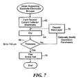
- the flowchart of Figure 7 shows the electrode formed on the surface of the electrolyte layer(s) during step 62.
- the electrode is formed by controllably distributing phases and particle sizes.
- the formed electrode is preferably a porous cathode such as shown in Figures 1 and 2 .
- the porous cathode can also be an individual or multiple layer composite such as, for example, as strontium doped lanthanum manganite-YSZ.
- the composite electrode can be screen printed as a layer(s) having a preferable thickness in the range of about 50 to 150 ⁇ m. This thickness depends on the printed layers used to form the electrode.
- the electrode is deposited as a power slurry that can comprise binder, dispersant, solvent, plasticizer and composite solids. These materials are milled and sieved to remove soft agglomerates before printing. As shown, the deposited slurry layer is dried during step 64 in a temperature range from about 100 to 400 °C. This temperature range preferably evaporates materials in the printed layer to form the porous electrode. The thickness of the electrode can then be measured in step 66 by a suitable technique including those previously described.
- the electrode can be formed by printing additional layers onto the electrolyte in step 70 and drying each layer until a thickness in the preferred range of about 50 to 150 ⁇ m is measured. As described above, these additional layers can be deposited with varying porosities to control gas transport phenomena and affect the efficiency of the electrode.
- This individual or multiple layer electrode structure formed on the electrode-electrolyte bi-layer comprises the multilayer fuel cell structure.
- the multilayer structure generally includes a dense electrolyte that is positioned between porous electrodes. Any moisture within the multilayer cell is preferably evaporated by uniformly heating the structure in a temperature range from about 125 to 150 °C.
- the structure can also be heated to remove binder from each of the cell layers in a temperature range from about 275 to 375 °C. This temperature range volatizes any plasticizer, dispersant or solvent remaining within each layer. Binder materials that are heated often leave a carbon residue, which can be removed by uniformly heating the structure in a temperature range from about 500 to 600 °C. This uniform heating is continued until a temperature of about 800 °C in order to decrease the time required for the thermal cycle and improve the process efficiency of the method.
- the structure is then fired during step 74 in a temperature range from about 1000 to 1500 °C to sinter the multilayer structure.
- the amount of time used to heat and fire the structure across the above temperature ranges can vary depending, for example, on the materials of the cell or a particular process.
- the fuel cell structure can be uniformly heated by a variable or multi-frequency microwave source.
- microwave sources are generally described in U.S. Patents Nos. 5,321,222 , 5,521,360 and 5,961,871 .
- the frequency and power level of the microwave source can be adjusted to provide efficient coupling of microwave energy to the cell structure.
- the microwave frequency can also be modulated or swept across a frequency band to provide an intended microwave spectrum. Alternatively, microwave energy could be provided at multiple frequencies.
- a microwave heating source is preferably used to uniformly heat the multilayer structure, other suitable heating processes that minimize the temperature gradient within the cell layers could be used.
- a multilayer fuel cell can be fired by convection and/or radiation heating such as used in a ceramic sintering process. These heating methods could also be carried out in an atmosphere of circulated gas. Temperatures for firing an SOFC can depend on the thermophysical properties of the electrolyte and electrode layers. Thus, different electrical heaters such as, for example, nickel-chromium, molybdenum ribbon, molybdenum-silicate or silicon-carbide can be used for certain cell structures.
- the method of the invention heats and fires the multilayer fuel cell in a single thermal cycle.
- This thermal cycle can be performed in a furnace having one or more chambers.
- the chamber(s) preferably contains a variable or multiple frequency microwave source for heating the cell and removing binder materials in the electrolyte and electrode structures.
- the chamber(s) also preferably includes a convection and/or radiation source for sintering the fuel cell.
- Such furnaces are described in U.S. Patent Application No. 10/775,542 assigned to BTU International, Incorporated.
- a single thermal cycle can also be performed as a batch or continuous process.
- the electrolyte of the multilayer cell structure is preferably an 8 mole percent YSZ solid conductor and the cathode and anode are strontium doped lanthanum manganite-YSZ and nickel-YSZ oxide ceramic composites, respectively.
- the electrolyte and electrode layers are also selected to have particle sizes in the range of nanometers or micrometers.
- Figure 8 shows an SOFC formed and fired with these materials. The preferred thickness for the dense electrolyte and each porous electrode is also shown.
- Process variables of the present invention can also be changed in order to, for example, decrease the time required for the thermal cycle and improve manufacturing efficiency. These variables can include temperature, time, atmosphere, particle size and/or particle distribution. Modifying these variables could also affect and improve interfacial contact and resistance between the layers as well as lower the internal stresses to prevent warping of the multilayer structure.
- the method of the invention can also be used to process an intermediate temperature SOFC device having, for example, oxygen pumps, sensors or other electrochemical devices.
Landscapes
- Chemical & Material Sciences (AREA)
- Engineering & Computer Science (AREA)
- Chemical Kinetics & Catalysis (AREA)
- Electrochemistry (AREA)
- General Chemical & Material Sciences (AREA)
- Manufacturing & Machinery (AREA)
- Materials Engineering (AREA)
- Sustainable Energy (AREA)
- Sustainable Development (AREA)
- Life Sciences & Earth Sciences (AREA)
- Ceramic Engineering (AREA)
- Composite Materials (AREA)
- Physics & Mathematics (AREA)
- Thermal Sciences (AREA)
- Inert Electrodes (AREA)
- Fuel Cell (AREA)
Applications Claiming Priority (2)
| Application Number | Priority Date | Filing Date | Title |
|---|---|---|---|
| US50174203P | 2003-09-10 | 2003-09-10 | |
| PCT/US2004/029571 WO2005027239A2 (en) | 2003-09-10 | 2004-09-10 | Process for solid oxide fuel cell manufature |
Publications (3)
| Publication Number | Publication Date |
|---|---|
| EP1671385A2 EP1671385A2 (en) | 2006-06-21 |
| EP1671385A4 EP1671385A4 (en) | 2009-03-25 |
| EP1671385B1 true EP1671385B1 (en) | 2013-01-02 |
Family
ID=34312303
Family Applications (1)
| Application Number | Title | Priority Date | Filing Date |
|---|---|---|---|
| EP04783704A Expired - Lifetime EP1671385B1 (en) | 2003-09-10 | 2004-09-10 | Process for solid oxide fuel cell manufacture |
Country Status (11)
| Country | Link |
|---|---|
| US (1) | US7485385B2 (enExample) |
| EP (1) | EP1671385B1 (enExample) |
| JP (1) | JP5015598B2 (enExample) |
| KR (1) | KR101136191B1 (enExample) |
| CN (1) | CN101061596B (enExample) |
| AU (1) | AU2004272186B8 (enExample) |
| BR (1) | BRPI0414240A (enExample) |
| CA (1) | CA2538224C (enExample) |
| CR (1) | CR8281A (enExample) |
| RU (1) | RU2362239C2 (enExample) |
| WO (1) | WO2005027239A2 (enExample) |
Cited By (1)
| Publication number | Priority date | Publication date | Assignee | Title |
|---|---|---|---|---|
| WO2017214247A1 (en) * | 2016-06-07 | 2017-12-14 | Navitas Systems, Llc | High loading electrodes |
Families Citing this family (48)
| Publication number | Priority date | Publication date | Assignee | Title |
|---|---|---|---|---|
| WO2005001959A2 (en) | 2003-06-09 | 2005-01-06 | Saint-Gobain Ceramics & Plastics, Inc. | Stack supported solid oxide fuel cell |
| CN1985397B (zh) * | 2004-06-10 | 2012-07-04 | 丹麦科技大学 | 固体氧化物燃料电池 |
| EP1844512B1 (en) * | 2004-12-28 | 2017-04-19 | Technical University of Denmark | Method of producing metal to glass, metal to metal or metal to ceramic connections |
| KR100924700B1 (ko) * | 2005-01-12 | 2009-11-03 | 테크니칼 유니버시티 오브 덴마크 | 소결 중 수축률 및 공극률이 조절된 다층 구조물의 제조방법, 상기 제조방법에 따라 제조된 다층 구조물 및 상기 다층 구조물을 포함하는 고체 산화물 연료전지 |
| AU2006208619B2 (en) * | 2005-01-31 | 2009-06-04 | Technical University Of Denmark | Redox-stable anode |
| WO2006082057A2 (en) * | 2005-02-02 | 2006-08-10 | Technical University Of Denmark | A method for producing a reversible solid oxid fuel cell |
| WO2007005767A1 (en) * | 2005-07-01 | 2007-01-11 | The Regents Of The University Of California | Advanced solid oxide fuel cell stack design for power generation |
| EP1760817B1 (en) * | 2005-08-31 | 2013-08-21 | Technical University of Denmark | Reversible solid oxide fuell cell stack and method for preparing same |
| JP4825215B2 (ja) * | 2005-09-20 | 2011-11-30 | 京セラ株式会社 | 燃料電池セルおよびその製法 |
| HUP0501201A2 (en) * | 2005-12-23 | 2007-07-30 | Cella H | Electrode for electrochemical cell working with high differential pressure difference, method for producing said electrode and electrochemical cell for using said electrode |
| JP5350218B2 (ja) | 2006-04-05 | 2013-11-27 | サン−ゴバン セラミックス アンド プラスティクス,インコーポレイティド | 高温結合されたセミラック相互接続を具備するsofc積層体及びその製造方法 |
| EP1928049A1 (en) | 2006-11-23 | 2008-06-04 | Technical University of Denmark | Thin solid oxide cell |
| DK2378600T3 (da) * | 2006-11-23 | 2013-07-01 | Univ Denmark Tech Dtu | Fremgangsmåde til fremstilling af reversible fastoxidceller |
| WO2008073481A2 (en) * | 2006-12-12 | 2008-06-19 | Ceramatec, Inc. | Electrodes for lanthanum gallate electrolyte-based electrochemical systems |
| US20080232032A1 (en) * | 2007-03-20 | 2008-09-25 | Avx Corporation | Anode for use in electrolytic capacitors |
| US20080248363A1 (en) * | 2007-04-06 | 2008-10-09 | Alfred University | Composite electrolyte material having high ionic conductivity and depleted electronic conductivity and method for producing same |
| ATE528812T1 (de) * | 2007-08-31 | 2011-10-15 | Univ Denmark Tech Dtu | Entfernung von verunreinigungsphasen aus elektrochemischen vorrichtungen |
| US20090110992A1 (en) * | 2007-10-30 | 2009-04-30 | Bloom Energy Corporation | SOFC electrode sintering by microwave heating |
| US20090151850A1 (en) * | 2007-12-14 | 2009-06-18 | Wei-Xin Kao | Process for fabrication of a fully dense electrolyte layer embedded in membrane electrolyte assembly of solid oxide fuel cell |
| US20110003084A1 (en) * | 2008-02-25 | 2011-01-06 | National Research Council Of Canada | Process of Making Ceria-Based Electrolyte Coating |
| EP2104165A1 (en) * | 2008-03-18 | 2009-09-23 | The Technical University of Denmark | An all ceramics solid oxide fuel cell |
| US8163437B2 (en) * | 2008-03-25 | 2012-04-24 | Fuelcell Energy, Inc. | Anode with ceramic additives for molten carbonate fuel cell |
| GB2469522A (en) * | 2009-04-17 | 2010-10-20 | Energy Conversion Technology As | Fuel cell apparatus and method for heating a fuel cell stack |
| EP2333883A1 (de) | 2009-11-18 | 2011-06-15 | Forschungszentrum Jülich Gmbh (FJZ) | Anode für eine Hochtemperatur-Brennstoffzelle sowie deren Herstellung |
| KR101362894B1 (ko) * | 2009-12-09 | 2014-02-14 | 한국세라믹기술원 | 전사 방법을 이용한 고체산화물 연료전지용 셀 제조방법 |
| DE102009057720A1 (de) * | 2009-12-10 | 2011-06-16 | Siemens Aktiengesellschaft | Batterie und Verfahren zum Betreiben einer Batterie |
| RU2414776C1 (ru) * | 2010-02-09 | 2011-03-20 | Учреждение Российской академии наук Институт электрофизики Уральского отделения РАН (ИЭФ УрО РАН) | Устойчивая суспензия изопропанольного шликера на поливинилбутиральной связке из нанопорошка с добавлением дисперсанта (варианты) и способ его получения |
| CN102917806A (zh) * | 2010-04-09 | 2013-02-06 | 加州大学评议会 | 制造具有多孔金属层的电化学装置的方法 |
| JP2012028088A (ja) * | 2010-07-21 | 2012-02-09 | Sumitomo Electric Ind Ltd | 膜電極複合体、燃料電池、ガス除害装置、および膜電極複合体の製造方法 |
| ES2408861T3 (es) * | 2010-07-07 | 2013-06-21 | Technical University Of Denmark | Método para sinterización |
| JP5833122B2 (ja) | 2010-08-17 | 2015-12-16 | ブルーム エナジー コーポレーション | 固体酸化物形燃料電池の作製方法 |
| JP2014154239A (ja) * | 2013-02-05 | 2014-08-25 | Seiko Epson Corp | 活物質成形体の製造方法、活物質成形体、リチウム電池の製造方法、およびリチウム電池 |
| WO2014126716A1 (en) | 2013-02-13 | 2014-08-21 | Phillips 66 Company | Electrolyte formation for a solid oxide fuel cell device |
| US9356298B2 (en) | 2013-03-15 | 2016-05-31 | Bloom Energy Corporation | Abrasion resistant solid oxide fuel cell electrode ink |
| WO2015025642A1 (ja) * | 2013-08-21 | 2015-02-26 | 株式会社村田製作所 | 電気化学素子用セラミック基体及びその製造方法並びに燃料電池及び燃料電池スタック |
| US9666891B2 (en) | 2013-10-08 | 2017-05-30 | Phillips 66 Company | Gas phase modification of solid oxide fuel cells |
| US10418657B2 (en) | 2013-10-08 | 2019-09-17 | Phillips 66 Company | Formation of solid oxide fuel cells by spraying |
| WO2015054065A1 (en) | 2013-10-08 | 2015-04-16 | Phillips 66 Company | Liquid phase modification of electrodes of solid oxide fuel cells |
| US20160362805A1 (en) * | 2013-11-01 | 2016-12-15 | Adam Clayton Powell, IV | Methods and apparatuses for increasing energy efficiency and improving membrane robustness in primary metal production |
| WO2015160751A1 (en) * | 2014-04-14 | 2015-10-22 | Ovonic Battery Company, Inc. | Shared electrode hybrid battery-fuel cell system |
| KR102119411B1 (ko) * | 2017-11-09 | 2020-06-08 | 한국화학연구원 | 다공성 복합체 전극의 제조방법 및 다공성 복합체 전극의 유기물 제거방법 |
| US11043338B2 (en) | 2017-11-09 | 2021-06-22 | Korea Research Institute Of Chemical Technology | Manufacturing method of porous composite electrode and organic removal method of porous composite electrode |
| DE102018217516A1 (de) * | 2018-10-12 | 2020-04-16 | Volkswagen Aktiengesellschaft | Verfahren zur Herstellung einer Elektrode für einen Akkumulator |
| DE102018217518A1 (de) * | 2018-10-12 | 2020-04-16 | Volkswagen Aktiengesellschaft | Verfahren zur Herstellung einer Elektrode für einen Akkumulator |
| CN109437903B (zh) * | 2018-12-20 | 2022-01-18 | 云南大学 | 提高掺杂氧化铈电解质烧结活性的方法 |
| WO2021025051A1 (ja) | 2019-08-06 | 2021-02-11 | 株式会社村田製作所 | 固体酸化物形燃料電池用電解質シート、固体酸化物形燃料電池用電解質シートの製造方法及び固体酸化物形燃料電池用単セル |
| US20220231317A1 (en) * | 2021-01-15 | 2022-07-21 | Bloom Energy Corporation | Method of manufacturing solid oxide electrolyzer cells using a continuous furnace |
| CN114034192B (zh) * | 2021-11-26 | 2025-06-20 | 华能国际电力股份有限公司 | 一种熔融碳酸盐燃料电池的电极烧结装置及方法 |
Family Cites Families (52)
| Publication number | Priority date | Publication date | Assignee | Title |
|---|---|---|---|---|
| US4000006A (en) * | 1975-09-02 | 1976-12-28 | United Technologies Corporation | Screen printing fuel cell electrolyte matrices |
| JPS5916831B2 (ja) | 1978-07-24 | 1984-04-18 | 日産自動車株式会社 | 膜構造型酸素センサ−の製造方法 |
| US4799936A (en) * | 1987-06-19 | 1989-01-24 | Combustion Engineering, Inc. | Process of forming conductive oxide layers in solid oxide fuel cells |
| US4997726A (en) | 1989-02-15 | 1991-03-05 | Sanyo Electric Co., Ltd. | Solid oxide electrolyte fuel cell |
| US5069987A (en) | 1990-07-06 | 1991-12-03 | Igr Enterprises, Inc. | Solid oxide fuel cell assembly |
| US5290642A (en) | 1990-09-11 | 1994-03-01 | Alliedsignal Aerospace | Method of fabricating a monolithic solid oxide fuel cell |
| US5143801A (en) * | 1990-10-22 | 1992-09-01 | Battelle Memorial Institute | Solid oxide fuel cells, and air electrode and electrical interconnection materials therefor |
| US5292599A (en) | 1991-09-27 | 1994-03-08 | Ngk Insulators, Ltd. | Cell units for solid oxide fuel cells and power generators using such cell units |
| US5529856A (en) * | 1993-01-14 | 1996-06-25 | Electric Power Research Institute | Fuel cell having solidified plasma components |
| KR100301152B1 (ko) | 1993-03-20 | 2001-11-30 | 킬레유니버시티 | 고체산화물연료전지구조체 |
| US5356730A (en) * | 1993-03-26 | 1994-10-18 | Alliedsignal Inc. | Monolithic fuel cell having improved interconnect layer |
| GB9403234D0 (en) | 1994-02-19 | 1994-04-13 | Rolls Royce Plc | A solid oxide fuel cell stack and a reactant distribution member therefor |
| GB9403198D0 (en) | 1994-02-19 | 1994-04-13 | Rolls Royce Plc | A solid oxide fuel cell stack |
| JPH07277849A (ja) * | 1994-04-13 | 1995-10-24 | Ngk Insulators Ltd | 多孔質焼結体、耐熱性電極及び固体電解質型燃料電池 |
| US6316138B1 (en) | 1994-07-11 | 2001-11-13 | Mitsubishi, Jukogyo Kabushiki Kaisha | Solid oxide electrolyte fuel cell |
| DE69518481T2 (de) * | 1994-09-13 | 2001-04-19 | Gunze Ltd., Ayabe | Gasundurchlässiger Schichtstoff aus Gummi und Kunststoff |
| US5725965A (en) * | 1995-04-25 | 1998-03-10 | Gas Research Institute | Stable high conductivity functionally gradient compositionally layered solid state electrolytes and membranes |
| US5993986A (en) | 1995-11-16 | 1999-11-30 | The Dow Chemical Company | Solide oxide fuel cell stack with composite electrodes and method for making |
| US5753385A (en) | 1995-12-12 | 1998-05-19 | Regents Of The University Of California | Hybrid deposition of thin film solid oxide fuel cells and electrolyzers |
| JPH09245813A (ja) * | 1996-03-06 | 1997-09-19 | Nippon Telegr & Teleph Corp <Ntt> | 固体電解質型燃料電池の製造方法 |
| CA2275229C (en) | 1996-12-20 | 2008-11-18 | Tokyo Gas Co., Ltd. | Fuel electrode of solid oxide fuel cell and process for the production of the same |
| US6228520B1 (en) | 1997-04-10 | 2001-05-08 | The Dow Chemical Company | Consinterable ceramic interconnect for solid oxide fuel cells |
| US5922486A (en) | 1997-05-29 | 1999-07-13 | The Dow Chemical Company | Cosintering of multilayer stacks of solid oxide fuel cells |
| US6099985A (en) | 1997-07-03 | 2000-08-08 | Gas Research Institute | SOFC anode for enhanced performance stability and method for manufacturing same |
| US6117302A (en) | 1998-08-18 | 2000-09-12 | Aluminum Company Of America | Fuel cell aluminum production |
| JP2000133280A (ja) * | 1998-10-19 | 2000-05-12 | Sof Co | 高性能固体酸化物燃料電池用アノ―ド |
| KR100341402B1 (ko) | 1999-03-09 | 2002-06-21 | 이종훈 | 고체산화물 연료전지의 단전지와 스택구조 |
| US6605316B1 (en) | 1999-07-31 | 2003-08-12 | The Regents Of The University Of California | Structures and fabrication techniques for solid state electrochemical devices |
| US6682842B1 (en) * | 1999-07-31 | 2004-01-27 | The Regents Of The University Of California | Composite electrode/electrolyte structure |
| KR100344936B1 (ko) | 1999-10-01 | 2002-07-19 | 한국에너지기술연구원 | 연료극 지지체식 원통형 고체산화물 연료전지 및 그 제조방법 |
| US6649296B1 (en) | 1999-10-15 | 2003-11-18 | Hybrid Power Generation Systems, Llc | Unitized cell solid oxide fuel cells |
| US6485852B1 (en) | 2000-01-07 | 2002-11-26 | Delphi Technologies, Inc. | Integrated fuel reformation and thermal management system for solid oxide fuel cell systems |
| DK174654B1 (da) | 2000-02-02 | 2003-08-11 | Topsoe Haldor As | Faststofoxid brændselscelle og anvendelser heraf |
| US6428920B1 (en) | 2000-05-18 | 2002-08-06 | Corning Incorporated | Roughened electrolyte interface layer for solid oxide fuel cells |
| WO2001091218A2 (en) * | 2000-05-22 | 2001-11-29 | Acumentrics Corporation | Electrode-supported solid state electrochemical cell |
| JP3690967B2 (ja) * | 2000-06-29 | 2005-08-31 | 株式会社日本触媒 | 固体電解質膜形成用スラリーおよびこれを用いた固体電解質膜 |
| JP4605885B2 (ja) | 2000-10-23 | 2011-01-05 | 東邦瓦斯株式会社 | 支持膜式固体電解質型燃料電池 |
| US6551734B1 (en) | 2000-10-27 | 2003-04-22 | Delphi Technologies, Inc. | Solid oxide fuel cell having a monolithic heat exchanger and method for managing thermal energy flow of the fuel cell |
| US6855451B2 (en) | 2000-11-08 | 2005-02-15 | Fuelcell Energy, Ltd. | Electrochemical cell interconnect |
| RU2197039C2 (ru) * | 2000-11-10 | 2003-01-20 | Государственное унитарное предприятие Государственный научный центр РФ Физико-энергетический институт им. акад. А.И. Лейпунского | Твердооксидный топливный элемент и способ его изготовления |
| US6803141B2 (en) | 2001-03-08 | 2004-10-12 | The Regents Of The University Of California | High power density solid oxide fuel cells |
| US7638222B2 (en) | 2001-03-28 | 2009-12-29 | Hexis Ag | Porous, gas permeable layer substructure for a thin, gas tight layer for use as a functional component in high temperature fuel cells |
| US6677070B2 (en) | 2001-04-19 | 2004-01-13 | Hewlett-Packard Development Company, L.P. | Hybrid thin film/thick film solid oxide fuel cell and method of manufacturing the same |
| US20020155227A1 (en) | 2001-04-23 | 2002-10-24 | Sulzer Markets And Technolgy Ag | Method for the manufacture of a functional ceramic layer |
| JP5110337B2 (ja) * | 2001-06-18 | 2012-12-26 | 株式会社豊田中央研究所 | 固体電解質型燃料電池用電極構造体およびその製造方法 |
| JP4840718B2 (ja) | 2001-08-14 | 2011-12-21 | 日産自動車株式会社 | 固体酸化物形燃料電池 |
| US6653009B2 (en) * | 2001-10-19 | 2003-11-25 | Sarnoff Corporation | Solid oxide fuel cells and interconnectors |
| US6949307B2 (en) | 2001-10-19 | 2005-09-27 | Sfco-Efs Holdings, Llc | High performance ceramic fuel cell interconnect with integrated flowpaths and method for making same |
| YU88103A (sh) | 2002-05-14 | 2006-08-17 | H.Lundbeck A/S. | Lecenje adhd |
| US20030232230A1 (en) * | 2002-06-12 | 2003-12-18 | Carter John David | Solid oxide fuel cell with enhanced mechanical and electrical properties |
| US6893769B2 (en) * | 2002-12-18 | 2005-05-17 | Hewlett-Packard Development Company, L.P. | Fuel cell assemblies and methods of making the same |
| US7838166B2 (en) | 2003-03-31 | 2010-11-23 | Tokyo Gas Co., Ltd. | Method for fabricating solid oxide fuel cell module |
-
2004
- 2004-09-10 US US10/939,116 patent/US7485385B2/en not_active Expired - Fee Related
- 2004-09-10 EP EP04783704A patent/EP1671385B1/en not_active Expired - Lifetime
- 2004-09-10 CN CN2004800328167A patent/CN101061596B/zh not_active Expired - Fee Related
- 2004-09-10 WO PCT/US2004/029571 patent/WO2005027239A2/en not_active Ceased
- 2004-09-10 KR KR1020067005088A patent/KR101136191B1/ko not_active Expired - Fee Related
- 2004-09-10 RU RU2006110158/09A patent/RU2362239C2/ru not_active IP Right Cessation
- 2004-09-10 JP JP2006526312A patent/JP5015598B2/ja not_active Expired - Fee Related
- 2004-09-10 BR BRPI0414240-3A patent/BRPI0414240A/pt not_active IP Right Cessation
- 2004-09-10 AU AU2004272186A patent/AU2004272186B8/en not_active Ceased
- 2004-09-10 CA CA2538224A patent/CA2538224C/en not_active Expired - Lifetime
-
2006
- 2006-03-10 CR CR8281A patent/CR8281A/es not_active Application Discontinuation
Cited By (5)
| Publication number | Priority date | Publication date | Assignee | Title |
|---|---|---|---|---|
| WO2017214247A1 (en) * | 2016-06-07 | 2017-12-14 | Navitas Systems, Llc | High loading electrodes |
| US10916765B2 (en) | 2016-06-07 | 2021-02-09 | Navitas Systems, Llc | High loading electrodes |
| US11430978B2 (en) | 2016-06-07 | 2022-08-30 | Navitas Systems, Llc | High loading electrodes |
| US11843111B2 (en) | 2016-06-07 | 2023-12-12 | Navitas Systems, Llc | High loading electrodes |
| US12444731B2 (en) | 2016-06-07 | 2025-10-14 | Navitas Systems, Llc | High loading electrodes |
Also Published As
| Publication number | Publication date |
|---|---|
| WO2005027239A3 (en) | 2007-03-29 |
| AU2004272186A1 (en) | 2005-03-24 |
| EP1671385A2 (en) | 2006-06-21 |
| EP1671385A4 (en) | 2009-03-25 |
| US20050089739A1 (en) | 2005-04-28 |
| BRPI0414240A (pt) | 2006-10-31 |
| US7485385B2 (en) | 2009-02-03 |
| KR20070019944A (ko) | 2007-02-16 |
| CR8281A (es) | 2007-08-28 |
| WO2005027239A2 (en) | 2005-03-24 |
| CN101061596B (zh) | 2010-08-18 |
| RU2362239C2 (ru) | 2009-07-20 |
| AU2004272186B8 (en) | 2010-02-18 |
| CN101061596A (zh) | 2007-10-24 |
| CA2538224C (en) | 2012-01-24 |
| JP5015598B2 (ja) | 2012-08-29 |
| RU2006110158A (ru) | 2007-10-20 |
| KR101136191B1 (ko) | 2012-04-17 |
| JP2007510255A (ja) | 2007-04-19 |
| CA2538224A1 (en) | 2005-03-24 |
| AU2004272186B2 (en) | 2009-10-29 |
Similar Documents
| Publication | Publication Date | Title |
|---|---|---|
| EP1671385B1 (en) | Process for solid oxide fuel cell manufacture | |
| US5670270A (en) | Electrode structure for solid state electrochemical devices | |
| EP2318328B1 (en) | Method for deposition of ceramic films | |
| EP1770816B1 (en) | Paste for an anode-supported solid oxide fuel cell and fabricating method thereof | |
| JP2008130568A (ja) | 可逆的固体酸化物電池を製造する改良された方法 | |
| JP7780438B2 (ja) | 固体酸化物用中間層 | |
| US20090110992A1 (en) | SOFC electrode sintering by microwave heating | |
| WO1998049738A1 (en) | Electrode structure for solid state electrochemical devices | |
| US8153331B2 (en) | Fabrication method of anode and electrolyte in solid oxide fuel cell | |
| GB2460877A (en) | Method of depositing crystalline ceramic films | |
| CN113258113B (zh) | 一种金属支撑固体氧化物燃料电池及其制备方法 | |
| WO2003034515A2 (en) | One-step consolidation process for manufacturing solid oxide fuel cells | |
| KR101669002B1 (ko) | 고체 산화물 연료 전지용 단위 전지 및 이의 제조 방법 | |
| MXPA06002691A (en) | Process for solid oxide fuel cell manufature | |
| KR100707117B1 (ko) | 연료극 지지형 고체산화물연료전지 및 그 제조방법 | |
| Beeaff et al. | 5 RE-OXIDATION OF NI/YSZ-INFILTRATED ZIRCONIA HONEYCOMB |
Legal Events
| Date | Code | Title | Description |
|---|---|---|---|
| PUAI | Public reference made under article 153(3) epc to a published international application that has entered the european phase |
Free format text: ORIGINAL CODE: 0009012 |
|
| 17P | Request for examination filed |
Effective date: 20060308 |
|
| AK | Designated contracting states |
Kind code of ref document: A2 Designated state(s): AT BE BG CH CY CZ DE DK EE ES FI FR GB GR HU IE IT LI LU MC NL PL PT RO SE SI SK TR |
|
| AX | Request for extension of the european patent |
Extension state: AL HR LT LV MK |
|
| DAX | Request for extension of the european patent (deleted) | ||
| PUAK | Availability of information related to the publication of the international search report |
Free format text: ORIGINAL CODE: 0009015 |
|
| RIN1 | Information on inventor provided before grant (corrected) |
Inventor name: PAL, UDAY, B. Inventor name: SECCOMBE, DONALD, A., JR. Inventor name: ORBECK, GARY Inventor name: GOPALAN, SRIKANTH |
|
| A4 | Supplementary search report drawn up and despatched |
Effective date: 20090219 |
|
| RIC1 | Information provided on ipc code assigned before grant |
Ipc: H01M 4/86 20060101AFI20090213BHEP Ipc: H01M 4/90 20060101ALI20090213BHEP Ipc: H01M 4/88 20060101ALI20090213BHEP Ipc: H01M 8/12 20060101ALI20090213BHEP |
|
| 17Q | First examination report despatched |
Effective date: 20090605 |
|
| GRAP | Despatch of communication of intention to grant a patent |
Free format text: ORIGINAL CODE: EPIDOSNIGR1 |
|
| GRAS | Grant fee paid |
Free format text: ORIGINAL CODE: EPIDOSNIGR3 |
|
| GRAA | (expected) grant |
Free format text: ORIGINAL CODE: 0009210 |
|
| AK | Designated contracting states |
Kind code of ref document: B1 Designated state(s): AT BE BG CH CY CZ DE DK EE ES FI FR GB GR HU IE IT LI LU MC NL PL PT RO SE SI SK TR |
|
| REG | Reference to a national code |
Ref country code: GB Ref legal event code: FG4D |
|
| REG | Reference to a national code |
Ref country code: CH Ref legal event code: EP Ref country code: AT Ref legal event code: REF Ref document number: 592039 Country of ref document: AT Kind code of ref document: T Effective date: 20130115 |
|
| REG | Reference to a national code |
Ref country code: IE Ref legal event code: FG4D |
|
| REG | Reference to a national code |
Ref country code: DE Ref legal event code: R096 Ref document number: 602004040654 Country of ref document: DE Effective date: 20130307 |
|
| REG | Reference to a national code |
Ref country code: CH Ref legal event code: NV Representative=s name: SCHNEIDER FELDMANN AG PATENT- UND MARKENANWAEL, CH |
|
| REG | Reference to a national code |
Ref country code: SE Ref legal event code: TRGR |
|
| REG | Reference to a national code |
Ref country code: AT Ref legal event code: MK05 Ref document number: 592039 Country of ref document: AT Kind code of ref document: T Effective date: 20130102 |
|
| REG | Reference to a national code |
Ref country code: NL Ref legal event code: VDEP Effective date: 20130102 |
|
| PG25 | Lapsed in a contracting state [announced via postgrant information from national office to epo] |
Ref country code: SI Free format text: LAPSE BECAUSE OF FAILURE TO SUBMIT A TRANSLATION OF THE DESCRIPTION OR TO PAY THE FEE WITHIN THE PRESCRIBED TIME-LIMIT Effective date: 20130102 |
|
| PG25 | Lapsed in a contracting state [announced via postgrant information from national office to epo] |
Ref country code: AT Free format text: LAPSE BECAUSE OF FAILURE TO SUBMIT A TRANSLATION OF THE DESCRIPTION OR TO PAY THE FEE WITHIN THE PRESCRIBED TIME-LIMIT Effective date: 20130102 Ref country code: BG Free format text: LAPSE BECAUSE OF FAILURE TO SUBMIT A TRANSLATION OF THE DESCRIPTION OR TO PAY THE FEE WITHIN THE PRESCRIBED TIME-LIMIT Effective date: 20130402 Ref country code: ES Free format text: LAPSE BECAUSE OF FAILURE TO SUBMIT A TRANSLATION OF THE DESCRIPTION OR TO PAY THE FEE WITHIN THE PRESCRIBED TIME-LIMIT Effective date: 20130413 Ref country code: CZ Free format text: LAPSE BECAUSE OF FAILURE TO SUBMIT A TRANSLATION OF THE DESCRIPTION OR TO PAY THE FEE WITHIN THE PRESCRIBED TIME-LIMIT Effective date: 20130102 Ref country code: BE Free format text: LAPSE BECAUSE OF FAILURE TO SUBMIT A TRANSLATION OF THE DESCRIPTION OR TO PAY THE FEE WITHIN THE PRESCRIBED TIME-LIMIT Effective date: 20130102 |
|
| PG25 | Lapsed in a contracting state [announced via postgrant information from national office to epo] |
Ref country code: PT Free format text: LAPSE BECAUSE OF FAILURE TO SUBMIT A TRANSLATION OF THE DESCRIPTION OR TO PAY THE FEE WITHIN THE PRESCRIBED TIME-LIMIT Effective date: 20130502 Ref country code: GR Free format text: LAPSE BECAUSE OF FAILURE TO SUBMIT A TRANSLATION OF THE DESCRIPTION OR TO PAY THE FEE WITHIN THE PRESCRIBED TIME-LIMIT Effective date: 20130403 Ref country code: PL Free format text: LAPSE BECAUSE OF FAILURE TO SUBMIT A TRANSLATION OF THE DESCRIPTION OR TO PAY THE FEE WITHIN THE PRESCRIBED TIME-LIMIT Effective date: 20130102 Ref country code: NL Free format text: LAPSE BECAUSE OF FAILURE TO SUBMIT A TRANSLATION OF THE DESCRIPTION OR TO PAY THE FEE WITHIN THE PRESCRIBED TIME-LIMIT Effective date: 20130102 |
|
| PG25 | Lapsed in a contracting state [announced via postgrant information from national office to epo] |
Ref country code: RO Free format text: LAPSE BECAUSE OF FAILURE TO SUBMIT A TRANSLATION OF THE DESCRIPTION OR TO PAY THE FEE WITHIN THE PRESCRIBED TIME-LIMIT Effective date: 20130102 Ref country code: DK Free format text: LAPSE BECAUSE OF FAILURE TO SUBMIT A TRANSLATION OF THE DESCRIPTION OR TO PAY THE FEE WITHIN THE PRESCRIBED TIME-LIMIT Effective date: 20130102 Ref country code: EE Free format text: LAPSE BECAUSE OF FAILURE TO SUBMIT A TRANSLATION OF THE DESCRIPTION OR TO PAY THE FEE WITHIN THE PRESCRIBED TIME-LIMIT Effective date: 20130102 Ref country code: SK Free format text: LAPSE BECAUSE OF FAILURE TO SUBMIT A TRANSLATION OF THE DESCRIPTION OR TO PAY THE FEE WITHIN THE PRESCRIBED TIME-LIMIT Effective date: 20130102 |
|
| PGFP | Annual fee paid to national office [announced via postgrant information from national office to epo] |
Ref country code: CH Payment date: 20130912 Year of fee payment: 10 |
|
| PLBE | No opposition filed within time limit |
Free format text: ORIGINAL CODE: 0009261 |
|
| STAA | Information on the status of an ep patent application or granted ep patent |
Free format text: STATUS: NO OPPOSITION FILED WITHIN TIME LIMIT |
|
| PG25 | Lapsed in a contracting state [announced via postgrant information from national office to epo] |
Ref country code: CY Free format text: LAPSE BECAUSE OF FAILURE TO SUBMIT A TRANSLATION OF THE DESCRIPTION OR TO PAY THE FEE WITHIN THE PRESCRIBED TIME-LIMIT Effective date: 20130102 |
|
| PGFP | Annual fee paid to national office [announced via postgrant information from national office to epo] |
Ref country code: GB Payment date: 20130904 Year of fee payment: 10 |
|
| 26N | No opposition filed |
Effective date: 20131003 |
|
| PG25 | Lapsed in a contracting state [announced via postgrant information from national office to epo] |
Ref country code: IT Free format text: LAPSE BECAUSE OF FAILURE TO SUBMIT A TRANSLATION OF THE DESCRIPTION OR TO PAY THE FEE WITHIN THE PRESCRIBED TIME-LIMIT Effective date: 20130102 |
|
| REG | Reference to a national code |
Ref country code: DE Ref legal event code: R097 Ref document number: 602004040654 Country of ref document: DE Effective date: 20131003 |
|
| PG25 | Lapsed in a contracting state [announced via postgrant information from national office to epo] |
Ref country code: MC Free format text: LAPSE BECAUSE OF FAILURE TO SUBMIT A TRANSLATION OF THE DESCRIPTION OR TO PAY THE FEE WITHIN THE PRESCRIBED TIME-LIMIT Effective date: 20130102 |
|
| REG | Reference to a national code |
Ref country code: FR Ref legal event code: ST Effective date: 20140530 |
|
| REG | Reference to a national code |
Ref country code: IE Ref legal event code: MM4A |
|
| PG25 | Lapsed in a contracting state [announced via postgrant information from national office to epo] |
Ref country code: IE Free format text: LAPSE BECAUSE OF NON-PAYMENT OF DUE FEES Effective date: 20130910 |
|
| PG25 | Lapsed in a contracting state [announced via postgrant information from national office to epo] |
Ref country code: FR Free format text: LAPSE BECAUSE OF NON-PAYMENT OF DUE FEES Effective date: 20130930 |
|
| PGFP | Annual fee paid to national office [announced via postgrant information from national office to epo] |
Ref country code: FI Payment date: 20140910 Year of fee payment: 11 |
|
| PGFP | Annual fee paid to national office [announced via postgrant information from national office to epo] |
Ref country code: SE Payment date: 20140911 Year of fee payment: 11 |
|
| REG | Reference to a national code |
Ref country code: CH Ref legal event code: PL |
|
| GBPC | Gb: european patent ceased through non-payment of renewal fee |
Effective date: 20140910 |
|
| PG25 | Lapsed in a contracting state [announced via postgrant information from national office to epo] |
Ref country code: TR Free format text: LAPSE BECAUSE OF FAILURE TO SUBMIT A TRANSLATION OF THE DESCRIPTION OR TO PAY THE FEE WITHIN THE PRESCRIBED TIME-LIMIT Effective date: 20130102 |
|
| PG25 | Lapsed in a contracting state [announced via postgrant information from national office to epo] |
Ref country code: HU Free format text: LAPSE BECAUSE OF FAILURE TO SUBMIT A TRANSLATION OF THE DESCRIPTION OR TO PAY THE FEE WITHIN THE PRESCRIBED TIME-LIMIT; INVALID AB INITIO Effective date: 20040910 Ref country code: LU Free format text: LAPSE BECAUSE OF NON-PAYMENT OF DUE FEES Effective date: 20130910 Ref country code: LI Free format text: LAPSE BECAUSE OF NON-PAYMENT OF DUE FEES Effective date: 20140930 Ref country code: CH Free format text: LAPSE BECAUSE OF NON-PAYMENT OF DUE FEES Effective date: 20140930 Ref country code: GB Free format text: LAPSE BECAUSE OF NON-PAYMENT OF DUE FEES Effective date: 20140910 |
|
| PGFP | Annual fee paid to national office [announced via postgrant information from national office to epo] |
Ref country code: DE Payment date: 20150902 Year of fee payment: 12 |
|
| REG | Reference to a national code |
Ref country code: SE Ref legal event code: EUG |
|
| PG25 | Lapsed in a contracting state [announced via postgrant information from national office to epo] |
Ref country code: SE Free format text: LAPSE BECAUSE OF NON-PAYMENT OF DUE FEES Effective date: 20150911 Ref country code: FI Free format text: LAPSE BECAUSE OF NON-PAYMENT OF DUE FEES Effective date: 20150910 |
|
| REG | Reference to a national code |
Ref country code: DE Ref legal event code: R119 Ref document number: 602004040654 Country of ref document: DE |
|
| PG25 | Lapsed in a contracting state [announced via postgrant information from national office to epo] |
Ref country code: DE Free format text: LAPSE BECAUSE OF NON-PAYMENT OF DUE FEES Effective date: 20170401 |