EP1665583B1 - Diversitäts-empfänger - Google Patents
Diversitäts-empfänger Download PDFInfo
- Publication number
- EP1665583B1 EP1665583B1 EP04769849A EP04769849A EP1665583B1 EP 1665583 B1 EP1665583 B1 EP 1665583B1 EP 04769849 A EP04769849 A EP 04769849A EP 04769849 A EP04769849 A EP 04769849A EP 1665583 B1 EP1665583 B1 EP 1665583B1
- Authority
- EP
- European Patent Office
- Prior art keywords
- signal
- diversity receiver
- receiving channel
- systems
- channel parameter
- Prior art date
- Legal status (The legal status is an assumption and is not a legal conclusion. Google has not performed a legal analysis and makes no representation as to the accuracy of the status listed.)
- Expired - Lifetime
Links
- 230000002123 temporal effect Effects 0.000 claims abstract description 22
- 238000012546 transfer Methods 0.000 claims abstract description 9
- 238000000034 method Methods 0.000 claims description 25
- 230000006870 function Effects 0.000 claims description 18
- 238000006243 chemical reaction Methods 0.000 claims description 10
- 238000004590 computer program Methods 0.000 claims description 10
- 238000012545 processing Methods 0.000 claims description 6
- 230000001131 transforming effect Effects 0.000 claims description 6
- 238000005070 sampling Methods 0.000 claims description 5
- 238000001914 filtration Methods 0.000 claims description 4
- 239000011159 matrix material Substances 0.000 claims description 4
- 230000001413 cellular effect Effects 0.000 claims description 2
- 238000010295 mobile communication Methods 0.000 claims description 2
- RZVAJINKPMORJF-UHFFFAOYSA-N Acetaminophen Chemical class CC(=O)NC1=CC=C(O)C=C1 RZVAJINKPMORJF-UHFFFAOYSA-N 0.000 claims 1
- 238000010586 diagram Methods 0.000 description 6
- 230000000694 effects Effects 0.000 description 5
- 238000005562 fading Methods 0.000 description 5
- 238000000926 separation method Methods 0.000 description 3
- 230000007704 transition Effects 0.000 description 3
- 238000009825 accumulation Methods 0.000 description 2
- 230000003044 adaptive effect Effects 0.000 description 2
- 230000005540 biological transmission Effects 0.000 description 2
- 239000000969 carrier Substances 0.000 description 2
- 238000011161 development Methods 0.000 description 2
- 230000018109 developmental process Effects 0.000 description 2
- 230000003993 interaction Effects 0.000 description 2
- 230000002452 interceptive effect Effects 0.000 description 2
- 230000005855 radiation Effects 0.000 description 2
- 230000009467 reduction Effects 0.000 description 2
- 230000009466 transformation Effects 0.000 description 2
- 230000006978 adaptation Effects 0.000 description 1
- 238000013459 approach Methods 0.000 description 1
- 230000015556 catabolic process Effects 0.000 description 1
- 238000010276 construction Methods 0.000 description 1
- 238000006731 degradation reaction Methods 0.000 description 1
- 230000001419 dependent effect Effects 0.000 description 1
- 238000013461 design Methods 0.000 description 1
- 230000001627 detrimental effect Effects 0.000 description 1
- 238000005516 engineering process Methods 0.000 description 1
- 230000000116 mitigating effect Effects 0.000 description 1
- 230000010363 phase shift Effects 0.000 description 1
- 238000011045 prefiltration Methods 0.000 description 1
- 230000008569 process Effects 0.000 description 1
- 238000001228 spectrum Methods 0.000 description 1
Images


Classifications
-
- H—ELECTRICITY
- H04—ELECTRIC COMMUNICATION TECHNIQUE
- H04B—TRANSMISSION
- H04B7/00—Radio transmission systems, i.e. using radiation field
- H04B7/02—Diversity systems; Multi-antenna system, i.e. transmission or reception using multiple antennas
- H04B7/04—Diversity systems; Multi-antenna system, i.e. transmission or reception using multiple antennas using two or more spaced independent antennas
- H04B7/08—Diversity systems; Multi-antenna system, i.e. transmission or reception using multiple antennas using two or more spaced independent antennas at the receiving station
- H04B7/0837—Diversity systems; Multi-antenna system, i.e. transmission or reception using multiple antennas using two or more spaced independent antennas at the receiving station using pre-detection combining
- H04B7/084—Equal gain combining, only phase adjustments
-
- H—ELECTRICITY
- H04—ELECTRIC COMMUNICATION TECHNIQUE
- H04B—TRANSMISSION
- H04B7/00—Radio transmission systems, i.e. using radiation field
- H04B7/02—Diversity systems; Multi-antenna system, i.e. transmission or reception using multiple antennas
- H04B7/04—Diversity systems; Multi-antenna system, i.e. transmission or reception using multiple antennas using two or more spaced independent antennas
- H04B7/08—Diversity systems; Multi-antenna system, i.e. transmission or reception using multiple antennas using two or more spaced independent antennas at the receiving station
- H04B7/0802—Diversity systems; Multi-antenna system, i.e. transmission or reception using multiple antennas using two or more spaced independent antennas at the receiving station using antenna selection
- H04B7/0822—Diversity systems; Multi-antenna system, i.e. transmission or reception using multiple antennas using two or more spaced independent antennas at the receiving station using antenna selection according to predefined selection scheme
Definitions
- the present invention in general relates to a diversity receiver having multiple receiving branches, and more particularly to a diversity receiver being suitable for receiving high rate radio signals while the receiver is moving at a high speed. Furthermore, the present invention relates to a method for canceling or at least reducing signal distortions of a radio signal received by a moving diversity receiver, and to a computer program stored on a record carrier or made available for download, said computer program being adapted to carry out a method for canceling or at least reducing signal distortions of a radio signal received by a moving diversity receiver.
- radio signals experience channel conditions that vary (often rapidly) with time. This is mainly caused by multipath radio signal propagation, wherein reflected waves may cancel each other at one location, but may enhance each other elsewhere.
- a well known model to describe this effect which is referred to as "fading" is to assume that the received signal consists of multiple reflected waves, each arriving from a different angle at the moving receive antenna. This results in slightly different Doppler shifts for each wave. The collection of Doppler shifts is called Doppler spread of a signal.
- the fading effects for a moving receiver are seen as time variations of the radio channel.
- Diversity is a known method to improve the reliability of reception of radio signals.
- at least two antennas are used to receive the radio signal. Signals from the at least two antennas are combined to improve the reliability of reception. If the channel is fading, an adaptation method is used to continuously ensure that the signals from the multiple antennas are combined in a constructive way.
- JP-A-04-185130 discloses a diversity receiver of the above mentioned type.
- a second antenna parted spatially with respect to a first antenna.
- the distance between the two antennas is spatially parted by ⁇ /3 (wherein ⁇ is a wavelength of a carrier) or over that, so that a reception signal from the one antenna and a reception signal from the other antenna are almost in non-correlation.
- OFDM Orthogonal Frequency Division Multiplexing
- a practical implementation of the OFDM modulation method typically involves a (Fast) Fourier Transformation of the user bits, before and after radio transmission.
- the data are divided into many parallel streams.
- Each stream is modulated on a different sub-carrier frequency.
- OFDM systems are designed such that each data symbol waveform is located around a particular sub-carrier frequency, and that its bandwidth is small enough to experience frequency-flat fading, when the signal is received over a (moderately) frequency-selective channel.
- the modulated sub-carriers comprise overlapping side lobes.
- the rectangular pulse shape leads to a spectrum according to a sinc function.
- These signal waveforms are carefully spaced in frequency and thereby designed to be orthogonal, i.e. not interfering with each other.
- a Doppler spread for example caused by fading, is detrimental to this orthogonality of the OFDM sub-carrier signals since arriving waves will interfere with other waves having different frequency offsets. This is called inter-carrier interference (ICI).
- EP-A-0 851 605 discloses a divensity receiver determining the spatial derivative of a channel parameter from the received signals.
- the first of the above objects is solved by a diversity receiver comprising a first receiving branch having associated thereto a first antenna element and at least a second receiving branch having associated thereto a second antenna element, the diversity receiver comprising first means for obtaining from a first signal on the first receiving branch and a second signal on the second receiving branch a third signal representing an estimation of the spatial derivative of at least one receiving channel parameter, characterized by the diversity receiver further comprising means (26, 28, 30, 32, 34, 36, 40) for interpreting the third signal as a temporal derivative of at least one receiving channel parameter, at least when the diversity receiver is moved, and using the temporal derivative to cancel or at least reduce signal distortions that occur due to time-variations of the receiving channel.
- the first of the above objects is solved by a method for canceling or at least reducing signal distortions of a radio signal received by a moving diversity receiver, especially a moving diversity receiver in accordance with the present invention, wherein the signal distortions occur due to time-variations of a receiving channel in a radio system, said method comprising the following steps: receiving the radio signal at two positions spaced less than ⁇ /2 and differing in the direction of motion; estimating the spatial derivative of at least one receiving channel parameter on the basis of the radio signal received at the two positions; interpreting the spatial derivative of the at least one receiving channel parameter as the temporal derivative of the at least one receiving channel parameter; and exploiting the temporal derivative of the at least one receiving channel parameter to cancel or at least reduce the signal distortions.
- the first of the above objects is solved by a computer program stored on a record carrier or made available for download, said computer program being adapted to carry out the following method for canceling or at least reducing signal distortions of a radio signal received by a moving diversity receiver: estimating, on the basis of a radio signal received at two positions spaced less than ⁇ /2 and differing in the direction of motion, the spatial derivative of at least one receiving channel parameter; interpreting the spatial derivative of the at least one receiving channel parameter as the temporal derivative of the at least one receiving channel parameter, and exploiting the temporal derivative of the at least one receiving channel parameter to cancel or at least reduce the signal distortions.
- first and the second antenna are vertical whips that are arranged in parallel, preferably extending from a common basis in opposite directions.
- the above mentioned aspects of the present invention are based on the finding that by estimating and exploiting the spatial derivative of the at least one receiving channel parameter, especially the receiving channel transfer function, besides advantages for a simplified tracking and estimation, an effective cancellation or at least a reduction of distortions may be achieved.
- This is particularly due to the fact that for a moving receiver the spatial derivative contains information concerning the temporal derivative.
- the spatial derivative contains information concerning the temporal derivative.
- ICI countermeasures there exist solutions based on the separation of wanted und unwanted signal components. This can involve the separation of individual frequency-shifted components, or the separation of (orthogonal) sub-carrier amplitudes and (interfering and/or crosstalking) derivatives of amplitudes.
- a significant portion of techniques used for cancellation or least reduction of ICI is based on the concept that the amplitudes of the sub-carrier describe receiving channel parameters, especially the transfer function of the wanted signal, whereas the temporal derivatives (i.e., changes) of these amplitudes cause ICI.
- the first antenna element and the second antenna element are preferably spaced less than ⁇ /2 and arranged behind each other in the direction of motion of the diversity receiver.
- the direction of motion particularly may be the direction of motion of a vehicle comprising the receiver.
- the first antenna element is preferably considered to be the main antenna receiving the main signal component, wherein the second antenna element follows at least substantially the same spatial path as the first one, but with a slight time lag.
- the first means preferably obtain the third signal as a difference between the first signal and the second signal.
- the spatial derivative of the receiving channel parameter especially of the channel transfer function
- the difference signal closely approximates the spatial derivative modulated by the user data of the signal.
- this modulated derivative is used directly to mitigate ICI in the main signal.
- the basic idea to exploit the spatial derivatives can also be applied in more sophisticated receiver architectures, whereby the clean derivatives, i.e., without modulation, are estimated from said difference signal and are used to enhance the performance of the channel estimation, synchronization and / or ICI mitigation algorithms.
- the diversity receiver according to the invention further comprises: second means for processing the third signal to obtain a fourth signal; third means for processing the first signal to obtain a fifth signal; and fourth means for combining the fourth signal and the fifth signal.
- the combining of the fourth signal and the fifth signal may, without being limited thereto, be achieved by an adder.
- first means, the second means, the third means, and the fourth means are fully or in part realized by hardware interacting with software and/or by discrete components.
- first, second, third, and fourth means are realized at least in part by a software controlled microprocessor.
- the second means perform one or more of the following functions: filtering, sampling, A/D-conversion, serial-to-parallel conversion, multiplying with a ramp function, (Fast) Fourier Transforming, multiplying with a crosstalk matrix, and signal weighting.
- the second means perform a signal weighting function comprising a multiplication with a weighting factor controlled to minimize the signal distortions.
- a weighting factor controlled to minimize the signal distortions.
- an adaptive control loop can be used to set the weighting factor to ensure that the correlation between the resulting output signal and the respective derivative is zero.
- the third means preferably perform one or more of the following functions: filtering, sampling, A/D-conversion, serial-to-parallel conversion, and (Fast) Fourier Transforming.
- the at least one receiving channel parameter is a receiving channel transfer function.
- different or related parameters such as attenuation, gain, phase shift, etc. may be considered.
- switching means for creating a virtual third antenna, there are provided switching means for switching from a signal on the first receiving branch to a corresponding signal on the second receiving branch.
- the switching preferably is done linearly and smoothly.
- the first antenna element and the second antenna element may be arranged in parallel but extend in opposite directions. With preferred embodiments the antennas extend from a common basis. In general, special constructions are possible to create an antenna system that receives signals at two closely spaced locations with small mutual interaction of the radiation pattern.
- the present invention may advantageously be used in one or more of the following systems: Orthogonal Frequency Division Multiplexing (OFDM) systems, Digital Audio Broadcasting (DAB) systems, Digital Video Broadband (DVB) systems, for example DVB-T systems, Digital Terrestrial Television Broadcasting (DTTB) systems, Code Division Multiple Access (CDMA) systems, for example cellular CDMA systems, Universal Mobile Telecommunications Systems (UMTS), the Global System for Mobile communications (GSM), Digital Enhanced Cordless Telecommunication (DECT) systems, wireless local area network systems, for example according to the standard 802.11a, 802.11 g, or HIPERLAN II.
- OFDM Orthogonal Frequency Division Multiplexing
- DAB Digital Audio Broadcasting
- DVD Digital Video Broadband
- DTTB Digital Terrestrial Television Broadcasting
- CDMA Code Division Multiple Access
- UMTS Universal Mobile Telecommunications Systems
- GSM Global System for Mobile communications
- DECT Digital Enhanced Cordless Telecommunication
- wireless local area network systems for example according to the standard 8
- the temporal derivatives causing distortions, especially ICI, for a moving receiver in fact are spatial derivatives. I.e., temporal changes of the signal occur predominantly because the antenna is moved in a spatially-changing, but temporally stationary environment. Therefore, it is possible to estimate the spatial derivative of the channel transfer function as the difference between the signals from two closely spaced antennas. For a moving antenna it is possible to estimate the temporal derivative as a spatial derivative, thus by subtracting two antenna signals. A condition is that the two antennas are spatially separated in the same direction as the direction of motion.
- Fig. 1 shows a simplified schematic block diagram of a first embodiment of the diversity receiver in accordance with the present invention.
- the diversity receiver illustrated in Fig. 1 comprises a first receiving branch 10 and a second receiving branch 14.
- the first receiving branch 10 comprises a first (front) antenna 12
- the second receiving branch 14 comprises a second (back) antenna 16.
- the first antenna element 12 and the second antenna element 16 are closely spaced by a distance d and arranged behind each other in the direction of motion v of the diversity receiver.
- the distance d will be smaller than ⁇ /2 (or even smaller than ⁇ /3), because for spacings beyond ⁇ /3 the approximation by considering only first-order derivatives becomes less accurate and this might reduce the effectiveness of the invention.
- first antenna element 12 and the second antenna element 16 may be mounted to a car and may be formed by an antenna system in accordance with the present invention, described later with reference to Fig. 4 .
- the antenna signals are constrained in bandwidth by RF pre-filters that are not shown in the drawings.
- the first means are formed by an adder/subtracter 18 which for obtaining the third signal 24 calculates the difference between the second signal 22 and the first signal 20, i.e.
- the third signal 24, i.e. the difference between the second signal 22 and the first signal 20, represents an estimation of the spatial derivative of the receiving channel transfer function. It is a basic idea of the present invention to interpret this spatial derivative of a receiving channel parameter, particularly the channel transfer function, as the temporal derivative of the respective receiving channel parameter, and to use the temporal derivative to cancel or at least reduce ICI or other distortions.
- the second means 26, 28, 30, 32 as well as the third means 36 comprise a sampling and serial-to-parallel converting unit 26 and 36, respectively.
- the interconnects between blocks 26, 36, 28, 38, 30, 40 preferably carry digital real or complex vector signals. That is, multiple, preferably N, values are multiplexed, for example using a state of the art bus technology.
- These units 26 and 36 sample and digitize the third signal 24 and the first signal 20, respectively, at a rate T and perform a serial-to-parallel conversion for a number of samples N that corresponds to a typical amount of data that is used by the diversity receiver. For example, in connection with DVB-T the number of samples N will preferably correspond to an OFDM symbol or frame. In the embodiment illustrated in Fig.
- a clock signal SYNC from the receiver is used to synchronize the serial-to-parallel conversions, for example to the OFDM signal timing structure of N-T periods, and preferably also to period T.
- S 1(t), and the circuitry 26, 28, 40 (the elements 28 and 40 are described below) connected to third signal 24, i.e. S2(t) - S1(t), are preferably duplicated to create a second output signal r a (k ⁇ T) (not shown in the drawings) which is sent to a second receiver (also not shown in the drawings).
- r a second output signal
- the main receiver seeing r(k ⁇ T), and the second receiver seeing r a (k ⁇ T) will experience synchronization discontinuities, and consequently bursts of errors at the instants N ⁇ T and N a T, respectively. Since N ⁇ T and N a ⁇ T in this case occur at different instances, the burst errors, both receiving branches can be combined into a new data stream without excessive errors during the switch instances.
- the digitized and serial-to-parallel converted third signal 24 contains samples S 2 (k ⁇ T)-S 1 (k ⁇ T) that are multiplied by a linearly increasing ramp function k/N in block 28 to obtain (k/N) ⁇ (S 2 (k ⁇ T)-S 1 (k ⁇ T)). Subsequently a multiplication with a weighting factor - ⁇ is performed in block 30 to obtain - ⁇ (k/N) ⁇ (S 2 (k ⁇ T)-S 1 (k ⁇ T)) as the fourth signal 34. Combining means shown in form of an adder 40 in Fig.1 then obtain the sum of the fourth signal 34 and the fifth signal 38, i.e.
- the weighting factor ⁇ is preferably controlled such that the receiving channel variations are minimized.
- ⁇ v/d
- ⁇ can be obtained from a speedometer signal measuring for example the car velocity v.
- ⁇ is the accumulation of the correlation values that have been computed during the last few symbol periods.
- Output signal r(t) contains at least reduced distortions like ICI compared to the first signal S1(t).
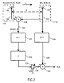
- Fig. 2 shows a simplified schematic block diagram of a second embodiment of the diversity receiver in accordance with the present invention, wherein the second embodiment executes a transition in the frequency domain.
- Radio signals are received by a first antenna element 112 associated to a first receiving branch 110 and a second antenna element 116 associated to a second receiving branch 114.
- a third signal 124 is obtained as the difference of a second signal 122 on the second receiving branch 114 and a first signal 120 on the first receiving branch 110 by first means in form of an adder/subtracter 118.
- the signals are fed to RF front ends, filtered, sampled into digital samples and converted serial-to-parallel by suitable equipment known in the art that at least in part is referred to as the second means in the language of the present invention.
- a Fast Fourier Transformation FFT
- blocks 126 part of the second means
- 136 part of the third means
- E the effect of ICI can accurately be described as a fixed crosstalk matrix E.
- ⁇ -v/d at block 130 (part of the second means)
- Examples of methods to derive ⁇ have been presented in embodiment of Fig. 1 .
- Fourth means in form of an adder 140 combine the fourth signal 134 and the fifth signal 138 output from block 136 to obtain an output signal H 0 S.
- Fig. 3 shows a flowchart illustrating an embodiment of the method in accordance with the present invention (steps S1 through S6), and also an embodiment of the method (steps S2 through S6) that may be carried out with the computer program in accordance with the present invention.
- step S1 a first signal S 1 (t) is obtained via a front antenna and a second signal S 2 (t) is obtained via a back antenna.
- the front antenna may for example be considered to be the main antenna receiving the main signal component.
- the back antenna follows the same spatial path as the front antenna, but with a slight time lag.
- Step S3 the first signal S 1 (t) and the third signal S 3 (t) are sampled, digitized at a rate T, and serial-to-parallel converted for a number of samples N to obtain first samples S 1 (k ⁇ T) and second samples S 2 (k ⁇ T).
- step S4 the samples [S 2 (k ⁇ T)-S 1 (k ⁇ T)] are multiplied by a (linearly increasing) ramp function k/N to obtain (k/N) ⁇ (S 2 (k ⁇ T)-S 1 (k ⁇ T)].
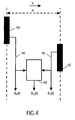
- Fig. 4 shows a simplified schematic block diagram of an antenna arrangement in accordance with the present invention as well as the use of switching means for creating a virtual antenna.
- the antenna system shown in Fig. 4 comprises a first antenna element 12 and a second antenna element 16.
- the first antenna element 12 and the second antenna element 16 are closely spaced by a distance d and arranged behind each other in the direction of motion v.
- the first antenna element 12 and the second antenna element 16 are arranged in parallel but extend, relative to a common basis, in opposite directions. This results in a small mutual interaction of the radiation patterns.
- switching means 42 for linearly, smoothly switching from a signal S 1 (t) on a first receiving branch 10 to a signal S 2 (t) on a second receiving branch 14. In good approximation this creates a virtual third antenna element located somewhere in between the first antenna element 12 and the second antenna element 16.
Landscapes
- Engineering & Computer Science (AREA)
- Computer Networks & Wireless Communication (AREA)
- Signal Processing (AREA)
- Radio Transmission System (AREA)
- Input Circuits Of Receivers And Coupling Of Receivers And Audio Equipment (AREA)
- Structure Of Receivers (AREA)
- Mobile Radio Communication Systems (AREA)
Claims (15)
- Diversitätsempfänger mit einem ersten Empfangszweig (10; 110) mit dem ein erstes Antennenelement (12; 112) assoziiert ist, und mit wenigstens einem zweiten Empfangszweig (14; 114), mit dem ein zweites Antennenelement (16; 116) assoziiert ist, wobei der Diversitätsempfänger erste Mittel (18; 180) aufweist, um aus einem ersten Signals (20; 120) in dem ersten Empfangszweig (10; 110) und ein zweites Signal (22; 122) in dem zweiten Empfangszweig (14; 114) ein drittes Signal (24; 124) zu erhalten, das eine Schätzung der räumlichen Abgeleiteten wenigstens eines Empfangskanalparameters darstellt, dadurch gekennzeichnet, dass der Diversitätsempfänger weiterhin Mittel (26, 28, 30, 32, 34, 36, 40) aufweist um das dritte Signal (24; 124) als eine zeitliche Abgeleitete des wenigstens einen Empfangskanalparameters zu interpretieren, wenigstens wenn der Diversitätsempfänger verlagert wird, und um die zeitliche Abgeleitete zum Löschen oder wenigstens zum Reduzieren der Signalverzerrungen, die wegen der Zeitvariationen des Empfangskanals auftreten, zu verwenden.
- Diversitätsempfänger nach Anspruch 1, wobei das erste Antennenelement (12; 112) und das zweite Antennenelement (16; 116) um weniger als λ/2 auseinander liegen und hinter einander in der Richtung der Bewegung (v) des Diversitätsempfänger vorgesehen sind.
- Diversitätsempfänger nach Anspruch 1, wobei die ersten Mittel (18; 118) das dritte Signal (24; 124) als eine Differenz zwischen dem ersten Signal (20; 120) und dem zweiten Signal (22; 122) erhalten.
- Diversitätsempfänger nach Anspruch 1, der weiterhin Folgendes umfasst;- zweite Mittel (26, 28, 30, 32; 126, 128, 130) zum Verarbeiten des dritten Signals (24; 124) zum Erhalten eines vierten Signals (34; 134);- dritte Mittel (36; 136) zum verarbeiten des ersten Signals (20; 230) zum Erhalten eines fünften Signals (28; 138); und- vierte Mittel (40; 140) zum Kombinieren des vierten Signals (34; 134) und des fünften Signals (38; 138) zum Erhalten eines Ausgangssignals (r(t); H0S).
- Diversitätsempfänger nach Anspruch 4, wobei die ersten Mittel (18; 118), die zweiten Mittel (26, 28, 30, 32; 126, 128, 130), die dritten Mittel (36; 136) und/oder die vierten Mittel (40; 140) völlig oder teilweise durch mit Software zusammenarbeitende Hardware oder durch diskrete Elemente verwirklicht sind.
- Diversitätsempfänger nach Anspruch 4, wobei die zweiten Mittel (26, 28, 30, 32; 126, 128, 130) eine oder mehrere der nachfolgenden Funktionen erfüllen: Filterung, Abtastung, Analog-Digital-Umwandlung, Serie-Parallel-Umwandlung, Multiplikation mit einer Anstiegsfunktion, Fourier-Transformation oder Schnell-Fourier-Transformation, Multiplikation mit einer Übersprechmatrix, und Signalgewichtung.
- Diversitätsempfänger nach Anspruch 4, wobei die zweiten Mittel (26, 28, 30, 32; 126, 128, 130) eine Signalgewichtungsfunktion mit einer Multiplikation mit einem Gewichtungsfaktor (α; d/v) durchführen, gesteuert zur Minimierung der Signalverzerrungen.
- Diversitätsempfänger nach Anspruch 4, wobei die dritten Mittel (36; 136) eine oder mehrere der nachfolgenden Funktionen durchführen: Filterung, Abtastung, Analog-Digital-Umwandlung, Serie-Parallel-Umwandlung und Fourier-Transformation oder Schnelll-Fourier-Transformation.
- Diversitätsempfänger nach Anspruch 1, wobei der wenigstens eine Empfangskanalparameter eine Empfangskanalübertragungsfunktion ist.
- Diversitätsempfänger nach Anspruch 1, wobei zum Schaffen eines virtuellen dritten Antennenelementes Schaltmittel (42) vorgesehen sind, und zwar zum Umschalten von einem Signal in dem ersten Empfangszweig (10) zu einem entsprechenden Signal in dem zweiten Empfangszweig (14).
- Diversitätsempfänger nach Anspruch 1, wobei das erste Antennenelement (12) und das zweite Antennenelement (16) parallel vorgesehen sind, sich aber in entgegengesetzten Richtungen erstrecken.
- Diversitätsempfänger nach Anspruch 1, wobei der Diversitätsempfänger dazu vorgesehen ist, in einem oder mehreren der nachfolgenden Systeme verwendet zu werden: OFDM Systemen ("Orthogonal Frequency Division Multiplexing") DAB Systemen ("Digital Audio Broadcasting"), DVB Systemen ("Digital Video Broadband"), beispielsweise DVB-T Systemen, DTTB Systemen ("Digital Terrestrial Television Broadcasting"), CDMA Systemen ("Code Division Multiple Access"), beispielsweise zellularen CDMA Systemen, UMTS Systemen ("Universal Mobile Telecommunications"), GSM ("Global System for Mobile communications"), DECT Systemen ("Digital Enhanced Cordless Telecommunication"), drahtlosen LAN Systemen, beispielsweise entsprechend dem Standard 802.11a, 802.11 g, oder HIPERLAN IL.
- Verfahren zum Löschen oder wenigstens Reduzieren von Signalverzerrungen eines Funksignals, das von einem sich verlagernden Diversitätsempfänger empfangen wird, insbesondere von einem sich verlagernden Diversitätsempfänger nach einem der Ansprüche 1 bis 12, wobei die Signalverzerrungen wegen Zeitschwankungen eines Empfangskanals in einem Funksystem auftreten, wobei das genannte Verfahren die nachfolgenden Verfahrensschritte umfasst:- das Empfangen des Funksignals an zwei Stellen, die in einem Abstand von weniger als λ/2 auseinander liegen und eine andere Bewegungsrichtung haben,- das Schätzen der räumlichen Ableitung wenigstens eines Empfangskanalparameters auf Basis des an den zwei Stellen empfangenen Funksignals,- das Interpretieren der räumlichen Ableitung des wenigstens einen Empfangskanalparameters als die zeitliche Ableitung des wenigstens einen Empfangskanalparameters; und- das Benutzen der zeitlichen Ableitung des wenigstens einen Empfangskanalparameters zum Löschen oder wenigstens Reduzieren der Signalverzerrungen.
- Verfahren nach Anspruch 13, wobei der Schritt der Schätzung der räumlichen Ableitung das Berechnen einer Differenz zwischen dem an der ersten Stelle der zwei um weniger als λ/2 auseinander liegenden Stellen empfangenen Funksignal und dem an einer zweiten Stelle der genannten zwei um weniger als λ/2 auseinander liegenden Stellen empfangenen Funksignal.
- Computerprogramm, gespeichert auf einem Aufzeichnungsträger oder zum Herunterladen zur Verfügung gestellt, wobei das genannte Computerprogramm dazu vorgesehen ist, das nachfolgende Verfahren zum Löschen oder wenigstens Reduzieren von Signalverzerrungen eines von einem sich verlagernden Diversitätsempfänger empfangenen Funksignals durchzuführen:- das Schätzen der räumlichen Ableitung wenigstens eines Empfangskanalparameters, und zwar auf Basis eines Funksignals, das an zwei Stellen empfangen wird, die um wenigster als λ/2 auseinander liegen und in der Bewegungsrichtung verschieden sind;- das Interpretieren der räumlichen Ableitung des wenigstens einen Empfangskanalparameters als die zeitliche Ableitung des wenigstens einen Empfangskanalparameters; und- das Benutzen der zeitlichen Ableitung des wenigstens einen Empfangskanalparameters zum Löschen oder wenigstens Reduzieren der Signalverzerrungen.
Priority Applications (1)
| Application Number | Priority Date | Filing Date | Title |
|---|---|---|---|
| EP04769849A EP1665583B1 (de) | 2003-09-03 | 2004-08-24 | Diversitäts-empfänger |
Applications Claiming Priority (3)
| Application Number | Priority Date | Filing Date | Title |
|---|---|---|---|
| EP03103281 | 2003-09-03 | ||
| EP04769849A EP1665583B1 (de) | 2003-09-03 | 2004-08-24 | Diversitäts-empfänger |
| PCT/IB2004/051554 WO2005022778A1 (en) | 2003-09-03 | 2004-08-24 | Diversity receiver |
Publications (2)
| Publication Number | Publication Date |
|---|---|
| EP1665583A1 EP1665583A1 (de) | 2006-06-07 |
| EP1665583B1 true EP1665583B1 (de) | 2008-10-22 |
Family
ID=34259245
Family Applications (1)
| Application Number | Title | Priority Date | Filing Date |
|---|---|---|---|
| EP04769849A Expired - Lifetime EP1665583B1 (de) | 2003-09-03 | 2004-08-24 | Diversitäts-empfänger |
Country Status (8)
| Country | Link |
|---|---|
| US (1) | US7761077B2 (de) |
| EP (1) | EP1665583B1 (de) |
| JP (1) | JP4653745B2 (de) |
| KR (1) | KR101058052B1 (de) |
| CN (1) | CN1846370B (de) |
| AT (1) | ATE412281T1 (de) |
| DE (1) | DE602004017339D1 (de) |
| WO (1) | WO2005022778A1 (de) |
Families Citing this family (2)
| Publication number | Priority date | Publication date | Assignee | Title |
|---|---|---|---|---|
| CN105229959A (zh) | 2013-05-27 | 2016-01-06 | 英派尔科技开发有限公司 | 针对高速车辆减小无线电通信中的失真 |
| GB201511369D0 (en) * | 2015-06-29 | 2015-08-12 | Univ Kwazulu Natal | A receive decorrelator for a wireless communication system |
Family Cites Families (24)
| Publication number | Priority date | Publication date | Assignee | Title |
|---|---|---|---|---|
| FR2087370A5 (de) * | 1970-05-15 | 1971-12-31 | Cit Alcatel | |
| US4097866A (en) * | 1977-02-10 | 1978-06-27 | The United States Of America As Represented By The Secretary Of The Air Force | Multilevel sidelobe canceller |
| FR2394815A1 (fr) * | 1977-06-17 | 1979-01-12 | Thomson Csf | Dispositif de protection contre un brouilleur depointe d'un radar, notamment d'un radar de poursuite aeroporte, et radar comportant un tel dispositif |
| JPS56168440A (en) * | 1980-05-30 | 1981-12-24 | Nissan Motor Co Ltd | Diversity receiver for car |
| JPS6090909U (ja) * | 1983-11-25 | 1985-06-21 | 島田理化工業株式会社 | 電波測位機用フエ−ジング対策アンテナ |
| US4969211A (en) * | 1985-05-13 | 1990-11-06 | Plessey Overseas Limited | Transceiver interference cancellation system |
| JPS62100034A (ja) * | 1985-10-26 | 1987-05-09 | Toshiba Corp | 妨害波除去装置の妨害周波数検出回路 |
| US4888593A (en) * | 1987-12-15 | 1989-12-19 | Signal Science, Inc. | Time difference of arrival geolocation method, etc. |
| US5152010A (en) * | 1989-12-29 | 1992-09-29 | American Nucleonics Corporation | Highly directive radio receiver employing relatively small antennas |
| US5125108A (en) * | 1990-02-22 | 1992-06-23 | American Nucleonics Corporation | Interference cancellation system for interference signals received with differing phases |
| JPH04185130A (ja) | 1990-11-20 | 1992-07-02 | Clarion Co Ltd | スペクトラム拡散通信用ダイバーシチ受信装置 |
| DE4040599C2 (de) | 1990-12-19 | 1994-08-04 | Telefunken Microelectron | Geschwindigkeits-Wegstreckensensor für Kraftfahrzeuganwendungen |
| DE4140741A1 (de) | 1991-12-11 | 1993-06-17 | Flachglas Ag | Verfahren zum betrieb einer mobilfunkanlage eines fahrzeuges, insbesondere eines kraftfahrzeuges |
| US5260711A (en) * | 1993-02-19 | 1993-11-09 | Mmtc, Inc. | Difference-in-time-of-arrival direction finders and signal sorters |
| US5777693A (en) * | 1994-10-04 | 1998-07-07 | Matsushita Electric Industrial Co., Ltd. | Diversity receiving apparatus for a mobile unit |
| DE4445850A1 (de) | 1994-12-22 | 1996-06-27 | Alcatel Mobile Comm Deutsch | Empfangsvorrichtung für Mobilfunk, insbesondere für Bahnmobilfunk |
| US5592471A (en) * | 1995-04-21 | 1997-01-07 | Cd Radio Inc. | Mobile radio receivers using time diversity to avoid service outages in multichannel broadcast transmission systems |
| DE19533268A1 (de) * | 1995-09-08 | 1997-03-13 | Becker Gmbh | Verfahren zum Betreiben eines Rundfunkempfängers |
| GB9602250D0 (en) * | 1996-02-05 | 1996-04-03 | Secr Defence | Collision warning system |
| JPH09284251A (ja) * | 1996-04-10 | 1997-10-31 | Jisedai Digital Television Hoso Syst Kenkyusho:Kk | 受信装置 |
| JP3657377B2 (ja) * | 1996-12-27 | 2005-06-08 | 松下電器産業株式会社 | 受信回路 |
| JP3831339B2 (ja) * | 2000-06-13 | 2006-10-11 | カリフォルニア インスティテュート オブ テクノロジー | 準光学グリッドアレイ用モード変換導波路アダプタ |
| US7130355B1 (en) * | 2001-07-25 | 2006-10-31 | At&T Corp. | Amelioration in inter-carrier interference in OFDM |
| JP3782330B2 (ja) * | 2001-09-14 | 2006-06-07 | 富士通株式会社 | Ofdm受信方法及びofdm受信装置 |
-
2004
- 2004-08-24 AT AT04769849T patent/ATE412281T1/de not_active IP Right Cessation
- 2004-08-24 KR KR1020067004554A patent/KR101058052B1/ko not_active Expired - Fee Related
- 2004-08-24 JP JP2006525240A patent/JP4653745B2/ja not_active Expired - Fee Related
- 2004-08-24 US US10/569,179 patent/US7761077B2/en not_active Expired - Fee Related
- 2004-08-24 WO PCT/IB2004/051554 patent/WO2005022778A1/en not_active Ceased
- 2004-08-24 CN CN2004800251610A patent/CN1846370B/zh not_active Expired - Fee Related
- 2004-08-24 DE DE602004017339T patent/DE602004017339D1/de not_active Expired - Lifetime
- 2004-08-24 EP EP04769849A patent/EP1665583B1/de not_active Expired - Lifetime
Also Published As
| Publication number | Publication date |
|---|---|
| US20070004364A1 (en) | 2007-01-04 |
| DE602004017339D1 (de) | 2008-12-04 |
| ATE412281T1 (de) | 2008-11-15 |
| US7761077B2 (en) | 2010-07-20 |
| JP4653745B2 (ja) | 2011-03-16 |
| EP1665583A1 (de) | 2006-06-07 |
| KR20060064666A (ko) | 2006-06-13 |
| JP2007504740A (ja) | 2007-03-01 |
| CN1846370B (zh) | 2012-07-18 |
| KR101058052B1 (ko) | 2011-08-19 |
| CN1846370A (zh) | 2006-10-11 |
| WO2005022778A1 (en) | 2005-03-10 |
Similar Documents
| Publication | Publication Date | Title |
|---|---|---|
| US8605843B2 (en) | Method and apparatus for signal acquisition in OFDM receivers | |
| CA2357916C (en) | Adaptive antenna array for mobile communication | |
| JP2003522465A (ja) | 偏波ダイバーシティを使用する線形信号分離 | |
| JP4374764B2 (ja) | アダプティブ受信機 | |
| US11722197B2 (en) | Receiver system | |
| KR20110030469A (ko) | 통신 시스템에서의 잔류 주파수 에러를 추정하는 방법 및 장치 | |
| US6711412B1 (en) | Interference mitigation in wireless communications by training of interfering signals | |
| JP4311132B2 (ja) | Ofdm伝送方式における受信装置 | |
| US7502431B2 (en) | Method and apparatus for estimating response characteristic, and receiving method and receiver utilizing the same | |
| US20050141641A1 (en) | Receiving method and receiving apparatus with adaptive array signal processing | |
| EP1530333A1 (de) | Verfahren zur Kanalschätzung in einem MIMO-OFDM System | |
| US7573961B2 (en) | Virtual-antenna receiver | |
| JP2003051768A (ja) | ダイバーシティ受信機 | |
| US7577194B2 (en) | Equalizer and equalization method | |
| JPH09284251A (ja) | 受信装置 | |
| US7761077B2 (en) | Diversity receiver | |
| JP2009519664A (ja) | 広帯域伝送システムにおいてシンボル時間誤差を推定する方法およびシステム | |
| JP2005057673A (ja) | マルチキャリア受信装置 | |
| JP2006014027A (ja) | 無線通信装置及び無線通信方法、並びにコンピュータ・プログラム | |
| JP2006050190A (ja) | 受信装置及び送信装置 | |
| JP4119763B2 (ja) | 干渉抑制装置及び干渉抑制システム | |
| JPH07154129A (ja) | Lms方式のアダプティブアレイアンテナ装置 | |
| JP3954849B2 (ja) | アダプティブ受信装置 | |
| JP2006222836A (ja) | 受信装置、受信回路、受信方法及び受信プログラム | |
| JP4236545B2 (ja) | ダイバーシティ受信用回り込みキャンセラ及び中継装置 |
Legal Events
| Date | Code | Title | Description |
|---|---|---|---|
| PUAI | Public reference made under article 153(3) epc to a published international application that has entered the european phase |
Free format text: ORIGINAL CODE: 0009012 |
|
| 17P | Request for examination filed |
Effective date: 20060403 |
|
| AK | Designated contracting states |
Kind code of ref document: A1 Designated state(s): AT BE BG CH CY CZ DE DK EE ES FI FR GB GR HU IE IT LI LU MC NL PL PT RO SE SI SK TR |
|
| DAX | Request for extension of the european patent (deleted) | ||
| 17Q | First examination report despatched |
Effective date: 20070328 |
|
| GRAP | Despatch of communication of intention to grant a patent |
Free format text: ORIGINAL CODE: EPIDOSNIGR1 |
|
| GRAS | Grant fee paid |
Free format text: ORIGINAL CODE: EPIDOSNIGR3 |
|
| GRAA | (expected) grant |
Free format text: ORIGINAL CODE: 0009210 |
|
| AK | Designated contracting states |
Kind code of ref document: B1 Designated state(s): AT BE BG CH CY CZ DE DK EE ES FI FR GB GR HU IE IT LI LU MC NL PL PT RO SE SI SK TR |
|
| REG | Reference to a national code |
Ref country code: GB Ref legal event code: FG4D |
|
| REG | Reference to a national code |
Ref country code: CH Ref legal event code: EP |
|
| REG | Reference to a national code |
Ref country code: IE Ref legal event code: FG4D |
|
| REF | Corresponds to: |
Ref document number: 602004017339 Country of ref document: DE Date of ref document: 20081204 Kind code of ref document: P |
|
| NLV1 | Nl: lapsed or annulled due to failure to fulfill the requirements of art. 29p and 29m of the patents act | ||
| PG25 | Lapsed in a contracting state [announced via postgrant information from national office to epo] |
Ref country code: ES Free format text: LAPSE BECAUSE OF FAILURE TO SUBMIT A TRANSLATION OF THE DESCRIPTION OR TO PAY THE FEE WITHIN THE PRESCRIBED TIME-LIMIT Effective date: 20090202 Ref country code: BG Free format text: LAPSE BECAUSE OF FAILURE TO SUBMIT A TRANSLATION OF THE DESCRIPTION OR TO PAY THE FEE WITHIN THE PRESCRIBED TIME-LIMIT Effective date: 20090122 Ref country code: AT Free format text: LAPSE BECAUSE OF FAILURE TO SUBMIT A TRANSLATION OF THE DESCRIPTION OR TO PAY THE FEE WITHIN THE PRESCRIBED TIME-LIMIT Effective date: 20081022 |
|
| PG25 | Lapsed in a contracting state [announced via postgrant information from national office to epo] |
Ref country code: NL Free format text: LAPSE BECAUSE OF FAILURE TO SUBMIT A TRANSLATION OF THE DESCRIPTION OR TO PAY THE FEE WITHIN THE PRESCRIBED TIME-LIMIT Effective date: 20081022 Ref country code: PL Free format text: LAPSE BECAUSE OF FAILURE TO SUBMIT A TRANSLATION OF THE DESCRIPTION OR TO PAY THE FEE WITHIN THE PRESCRIBED TIME-LIMIT Effective date: 20081022 Ref country code: FI Free format text: LAPSE BECAUSE OF FAILURE TO SUBMIT A TRANSLATION OF THE DESCRIPTION OR TO PAY THE FEE WITHIN THE PRESCRIBED TIME-LIMIT Effective date: 20081022 Ref country code: PT Free format text: LAPSE BECAUSE OF FAILURE TO SUBMIT A TRANSLATION OF THE DESCRIPTION OR TO PAY THE FEE WITHIN THE PRESCRIBED TIME-LIMIT Effective date: 20090323 Ref country code: SI Free format text: LAPSE BECAUSE OF FAILURE TO SUBMIT A TRANSLATION OF THE DESCRIPTION OR TO PAY THE FEE WITHIN THE PRESCRIBED TIME-LIMIT Effective date: 20081022 |
|
| PG25 | Lapsed in a contracting state [announced via postgrant information from national office to epo] |
Ref country code: BE Free format text: LAPSE BECAUSE OF FAILURE TO SUBMIT A TRANSLATION OF THE DESCRIPTION OR TO PAY THE FEE WITHIN THE PRESCRIBED TIME-LIMIT Effective date: 20081022 Ref country code: DK Free format text: LAPSE BECAUSE OF FAILURE TO SUBMIT A TRANSLATION OF THE DESCRIPTION OR TO PAY THE FEE WITHIN THE PRESCRIBED TIME-LIMIT Effective date: 20081022 Ref country code: RO Free format text: LAPSE BECAUSE OF FAILURE TO SUBMIT A TRANSLATION OF THE DESCRIPTION OR TO PAY THE FEE WITHIN THE PRESCRIBED TIME-LIMIT Effective date: 20081022 Ref country code: EE Free format text: LAPSE BECAUSE OF FAILURE TO SUBMIT A TRANSLATION OF THE DESCRIPTION OR TO PAY THE FEE WITHIN THE PRESCRIBED TIME-LIMIT Effective date: 20081022 |
|
| PLBE | No opposition filed within time limit |
Free format text: ORIGINAL CODE: 0009261 |
|
| STAA | Information on the status of an ep patent application or granted ep patent |
Free format text: STATUS: NO OPPOSITION FILED WITHIN TIME LIMIT |
|
| PG25 | Lapsed in a contracting state [announced via postgrant information from national office to epo] |
Ref country code: IT Free format text: LAPSE BECAUSE OF FAILURE TO SUBMIT A TRANSLATION OF THE DESCRIPTION OR TO PAY THE FEE WITHIN THE PRESCRIBED TIME-LIMIT Effective date: 20081022 Ref country code: SE Free format text: LAPSE BECAUSE OF FAILURE TO SUBMIT A TRANSLATION OF THE DESCRIPTION OR TO PAY THE FEE WITHIN THE PRESCRIBED TIME-LIMIT Effective date: 20090122 Ref country code: CZ Free format text: LAPSE BECAUSE OF FAILURE TO SUBMIT A TRANSLATION OF THE DESCRIPTION OR TO PAY THE FEE WITHIN THE PRESCRIBED TIME-LIMIT Effective date: 20081022 |
|
| 26N | No opposition filed |
Effective date: 20090723 |
|
| PG25 | Lapsed in a contracting state [announced via postgrant information from national office to epo] |
Ref country code: SK Free format text: LAPSE BECAUSE OF FAILURE TO SUBMIT A TRANSLATION OF THE DESCRIPTION OR TO PAY THE FEE WITHIN THE PRESCRIBED TIME-LIMIT Effective date: 20081022 |
|
| PG25 | Lapsed in a contracting state [announced via postgrant information from national office to epo] |
Ref country code: MC Free format text: LAPSE BECAUSE OF NON-PAYMENT OF DUE FEES Effective date: 20090831 |
|
| REG | Reference to a national code |
Ref country code: CH Ref legal event code: PL |
|
| PG25 | Lapsed in a contracting state [announced via postgrant information from national office to epo] |
Ref country code: LI Free format text: LAPSE BECAUSE OF NON-PAYMENT OF DUE FEES Effective date: 20090831 Ref country code: CH Free format text: LAPSE BECAUSE OF NON-PAYMENT OF DUE FEES Effective date: 20090831 |
|
| REG | Reference to a national code |
Ref country code: IE Ref legal event code: MM4A |
|
| PG25 | Lapsed in a contracting state [announced via postgrant information from national office to epo] |
Ref country code: IE Free format text: LAPSE BECAUSE OF NON-PAYMENT OF DUE FEES Effective date: 20090824 |
|
| PG25 | Lapsed in a contracting state [announced via postgrant information from national office to epo] |
Ref country code: GR Free format text: LAPSE BECAUSE OF FAILURE TO SUBMIT A TRANSLATION OF THE DESCRIPTION OR TO PAY THE FEE WITHIN THE PRESCRIBED TIME-LIMIT Effective date: 20090123 |
|
| PG25 | Lapsed in a contracting state [announced via postgrant information from national office to epo] |
Ref country code: LU Free format text: LAPSE BECAUSE OF NON-PAYMENT OF DUE FEES Effective date: 20090824 |
|
| PG25 | Lapsed in a contracting state [announced via postgrant information from national office to epo] |
Ref country code: HU Free format text: LAPSE BECAUSE OF FAILURE TO SUBMIT A TRANSLATION OF THE DESCRIPTION OR TO PAY THE FEE WITHIN THE PRESCRIBED TIME-LIMIT Effective date: 20090423 |
|
| PG25 | Lapsed in a contracting state [announced via postgrant information from national office to epo] |
Ref country code: TR Free format text: LAPSE BECAUSE OF FAILURE TO SUBMIT A TRANSLATION OF THE DESCRIPTION OR TO PAY THE FEE WITHIN THE PRESCRIBED TIME-LIMIT Effective date: 20081022 |
|
| PG25 | Lapsed in a contracting state [announced via postgrant information from national office to epo] |
Ref country code: CY Free format text: LAPSE BECAUSE OF FAILURE TO SUBMIT A TRANSLATION OF THE DESCRIPTION OR TO PAY THE FEE WITHIN THE PRESCRIBED TIME-LIMIT Effective date: 20081022 |
|
| REG | Reference to a national code |
Ref country code: DE Ref legal event code: R082 Ref document number: 602004017339 Country of ref document: DE Representative=s name: MEISSNER, BOLTE & PARTNER GBR, DE |
|
| REG | Reference to a national code |
Ref country code: DE Ref legal event code: R082 Ref document number: 602004017339 Country of ref document: DE Representative=s name: MEISSNER BOLTE PATENTANWAELTE RECHTSANWAELTE P, DE Effective date: 20140328 Ref country code: DE Ref legal event code: R081 Ref document number: 602004017339 Country of ref document: DE Owner name: KONINKLIJKE PHILIPS N.V., NL Free format text: FORMER OWNER: KONINKLIJKE PHILIPS ELECTRONICS N.V., EINDHOVEN, NL Effective date: 20140328 Ref country code: DE Ref legal event code: R082 Ref document number: 602004017339 Country of ref document: DE Representative=s name: MEISSNER, BOLTE & PARTNER GBR, DE Effective date: 20140328 |
|
| REG | Reference to a national code |
Ref country code: FR Ref legal event code: CA Effective date: 20141126 Ref country code: FR Ref legal event code: CD Owner name: KONINKLIJKE PHILIPS N.V., NL Effective date: 20141126 |
|
| REG | Reference to a national code |
Ref country code: FR Ref legal event code: PLFP Year of fee payment: 13 |
|
| PGFP | Annual fee paid to national office [announced via postgrant information from national office to epo] |
Ref country code: GB Payment date: 20160831 Year of fee payment: 13 |
|
| PGFP | Annual fee paid to national office [announced via postgrant information from national office to epo] |
Ref country code: FR Payment date: 20160825 Year of fee payment: 13 |
|
| PGFP | Annual fee paid to national office [announced via postgrant information from national office to epo] |
Ref country code: DE Payment date: 20161031 Year of fee payment: 13 |
|
| REG | Reference to a national code |
Ref country code: DE Ref legal event code: R119 Ref document number: 602004017339 Country of ref document: DE |
|
| GBPC | Gb: european patent ceased through non-payment of renewal fee |
Effective date: 20170824 |
|
| REG | Reference to a national code |
Ref country code: FR Ref legal event code: ST Effective date: 20180430 |
|
| PG25 | Lapsed in a contracting state [announced via postgrant information from national office to epo] |
Ref country code: GB Free format text: LAPSE BECAUSE OF NON-PAYMENT OF DUE FEES Effective date: 20170824 Ref country code: DE Free format text: LAPSE BECAUSE OF NON-PAYMENT OF DUE FEES Effective date: 20180301 |
|
| PG25 | Lapsed in a contracting state [announced via postgrant information from national office to epo] |
Ref country code: FR Free format text: LAPSE BECAUSE OF NON-PAYMENT OF DUE FEES Effective date: 20170831 |