EP1664579B1 - Einzelrohrkolbenventilsystem mit selektiver entlüftung - Google Patents
Einzelrohrkolbenventilsystem mit selektiver entlüftung Download PDFInfo
- Publication number
- EP1664579B1 EP1664579B1 EP04782227A EP04782227A EP1664579B1 EP 1664579 B1 EP1664579 B1 EP 1664579B1 EP 04782227 A EP04782227 A EP 04782227A EP 04782227 A EP04782227 A EP 04782227A EP 1664579 B1 EP1664579 B1 EP 1664579B1
- Authority
- EP
- European Patent Office
- Prior art keywords
- blow
- passages
- piston
- face
- disc
- Prior art date
- Legal status (The legal status is an assumption and is not a legal conclusion. Google has not performed a legal analysis and makes no representation as to the accuracy of the status listed.)
- Expired - Lifetime
Links
- 239000012530 fluid Substances 0.000 claims description 85
- 239000006096 absorbing agent Substances 0.000 claims description 32
- 230000035939 shock Effects 0.000 claims description 32
- 230000036316 preload Effects 0.000 claims description 23
- 238000000034 method Methods 0.000 claims description 15
- 125000006850 spacer group Chemical group 0.000 claims description 9
- 238000007789 sealing Methods 0.000 claims description 7
- 230000006835 compression Effects 0.000 claims description 4
- 238000007906 compression Methods 0.000 claims description 4
- 238000004891 communication Methods 0.000 claims description 3
- 230000003247 decreasing effect Effects 0.000 claims description 2
- 238000009826 distribution Methods 0.000 claims description 2
- 238000013016 damping Methods 0.000 description 8
- 239000000463 material Substances 0.000 description 6
- 241000283216 Phocidae Species 0.000 description 5
- 229910000639 Spring steel Inorganic materials 0.000 description 4
- 229910052751 metal Inorganic materials 0.000 description 3
- 239000002184 metal Substances 0.000 description 3
- 229910000831 Steel Inorganic materials 0.000 description 2
- 238000006073 displacement reaction Methods 0.000 description 2
- 238000000926 separation method Methods 0.000 description 2
- 239000010959 steel Substances 0.000 description 2
- 229910001208 Crucible steel Inorganic materials 0.000 description 1
- 230000001133 acceleration Effects 0.000 description 1
- 230000004913 activation Effects 0.000 description 1
- 230000004075 alteration Effects 0.000 description 1
- 230000000712 assembly Effects 0.000 description 1
- 238000000429 assembly Methods 0.000 description 1
- 230000008859 change Effects 0.000 description 1
- 238000010586 diagram Methods 0.000 description 1
- 238000004519 manufacturing process Methods 0.000 description 1
- 229910001092 metal group alloy Inorganic materials 0.000 description 1
- 150000002739 metals Chemical class 0.000 description 1
- 230000004048 modification Effects 0.000 description 1
- 238000012986 modification Methods 0.000 description 1
- 229910001220 stainless steel Inorganic materials 0.000 description 1
- 239000010935 stainless steel Substances 0.000 description 1
- 238000003860 storage Methods 0.000 description 1
- 239000000725 suspension Substances 0.000 description 1
Images


Classifications
-
- F—MECHANICAL ENGINEERING; LIGHTING; HEATING; WEAPONS; BLASTING
- F16—ENGINEERING ELEMENTS AND UNITS; GENERAL MEASURES FOR PRODUCING AND MAINTAINING EFFECTIVE FUNCTIONING OF MACHINES OR INSTALLATIONS; THERMAL INSULATION IN GENERAL
- F16F—SPRINGS; SHOCK-ABSORBERS; MEANS FOR DAMPING VIBRATION
- F16F9/00—Springs, vibration-dampers, shock-absorbers, or similarly-constructed movement-dampers using a fluid or the equivalent as damping medium
- F16F9/32—Details
- F16F9/34—Special valve constructions; Shape or construction of throttling passages
- F16F9/348—Throttling passages in the form of annular discs or other plate-like elements which may or may not have a spring action, operating in opposite directions or singly, e.g. annular discs positioned on top of the valve or piston body
- F16F9/3485—Throttling passages in the form of annular discs or other plate-like elements which may or may not have a spring action, operating in opposite directions or singly, e.g. annular discs positioned on top of the valve or piston body characterised by features of supporting elements intended to guide or limit the movement of the annular discs
Definitions
- the present invention generally relates to automotive shock absorbers. More specifically, the present invention relates to a hydraulic flow control assembly operable as valves which allow greater tunability of the shock absorber.
- Shock absorbers are used in conjunction with automotive suspension systems to absorb unwanted vibrations which occur during driving. Shock absorbers are generally connected between the sprung portion (body) and the unsprung portion (wheels) of the automobile.
- a piston is located within a working chamber defined by a pressure tube of the shock absorber, with the piston being connected to the sprung portion of the automobile through a piston rod.
- the pressure tube is connected to the unsprung portion of the vehicle by one of the methods known in the art. Because the piston is able, through valving, to limit the flow of damping fluid between opposite sides of the piston when the shock absorber is compressed or extended, the shock absorber is able to produce a damping force which damps the unwanted vibration which would otherwise be transmitted from the unsprung portion to the sprung portion of the automobile.
- JP6 185562 A corresponding to the preamble of independent product claim 1 or 17 discloses a shock absorber which has one set of fluid passages that are utilized in compression and two sets of fluid passages that are utilized in expansion. This allows different flow values in different directions of piston travel. The size of the two sets of flow passages that are utilized in expansion can be set independently from each other.
- Shock absorbers have been developed to provide different damping characteristics depending upon the speed or acceleration of the piston within the pressure tube. Because of the exponential relation between the pressure drop and flow rate, it is difficult to obtain a damping force at relatively low piston velocities, particularly at velocities near zero. Low speed damping force is important to vehicle handling since most vehicle handling events are controlled by low speed vehicle body velocities. It is also important to control damping force over the broad range of pressures generated across the piston as the piston velocity increases.
- a piston in D1 comprises at least one passage that extends generally between a first and a second chamber of the hydraulic damper.
- the passage is operate and closed by a valve member.
- devices operably opens al an individually adjustable a shock absorber piston assembly comprises: a piston having a first face and an opposed second face;a first plurality of fluid passages extending from said first face to said second face through said piston, wherein said first plurality of fluid passages comprises a first set of blow-off passages and a second set of blow-off passages: a first blow-off disc engaging said first face to seal said first set of blow-off passages; a second blow-off disc engaging said second face to seal said second set of blow-off passages; a second plurality of fluid passages extending from said first face to said second face through said piston, wherein said second plurality of fluid passages are separate from and smaller in flow area than said first plurality of fluid passages; a first bleed plate engaging said first face to seal at least one of said second plurality of fluid passages; and a second bleed plate engaging said second face to seal at least one of said second plurality of fluid passages,wherein a plurality of passage
- a shock absorber fluid flow control assembly includes a piston having a first face and an opposed second face.
- a pair of fluid passage sets formed through the piston include a first one of the fluid passage sets isolable at the first face and a second one of the fluid passage sets isolable at the second face.
- a plurality of passages in each fluid passage set each have a passage flow area selected from a different one of a plurality of passage flow areas.
- a pair of blow-off discs each operably seal one of the fluid passage sets, including a first blow-off disc in displaceable contact with the first face and a second blow-off disc in displaceable contact with the second face.
- a fluid pressure acting on one of the first face and the second face operably acts through one of the fluid passage sets to initially angularly displace and subsequently to fully open one of the pair of blow-off discs.
- a method is provided to control fluid flow across a piston assembly of a shock absorber, the piston assembly having a first face and an opposed second face, and a first and a second plurality of fluid passages, wherein said first plurality of fluid passages comprises a first set of blow-off passages and a second set of blow-off passages: the method comprising:
- Figure 1 is a perspective view of a piston assembly of the present invention disposed within a piston tube of a shock absorber;
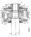
- Figure 2 is a cross sectional view taken at Section 2-2 of Figure 1 identifying details of the first embodiment of the present invention
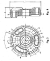
- Figure 3 is a plan view of a piston according to the first embodiment of the present invention.
- Figure 4 is a cross-sectional view taken at Section 4-4 of Figure 3 ;
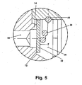
- Figure 5 is an exploded partial sectional view taken from Figure 2 identifying the details of an exemplary bleed passage and bleed plate according to a preferred embodiment of the present invention
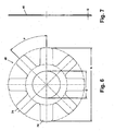
- Figure 6 is a plan view of an interface disc according to a preferred embodiment of the present invention.
- Figure 7 is a side elevation view of the interface disc of Figure 6 ;
- Figure 8 is a cross-sectional view similar to Figure 2 showing another preferred embodiment of the present invention.
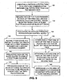
- Figure 9 is a flow diagram of the method steps to control fluid flow across a piston assemble of the present invention.
- Figure 10 is a side elevational view of an assembled shock absorber incorporating a piston assembly of the present invention.
- a piston assembly 10 includes a piston 12 fastenably connected to a piston rod 14 by a nut 16.
- Piston assembly 10 is slideably disposed within a tube 18 and is free to slide within tube 18 in the direction of piston travel arrows "A".
- Piston 12 divides tube 18 into a first working chamber 20 and a second working chamber 22 respectively.
- a fluid 24 in either first working chamber 20 or second working chamber 22 flows between either of the working chambers when piston 12 slides within tube 18. Fluid flow is controlled by a plurality of flow control devices 26 which will be described in further detail in reference to Figure 2 .
- Piston assembly 10 and tube 18 share a common longitudinal centerline "B". Fluid 24 within tube 18 is prevented from bypassing flow control devices 26 by a seal 28 circumferentially disposed about piston 12.
- piston 12 of piston assembly 10 includes at least one bleed passage 30 which is isolable to allow flow across piston 12 from either a first face "C” toward a second face “D” or from second face “D” toward first face “C” of piston 12.
- a bleed plate 32 is disposed against first face “C” to isolate a first bleed passage 30'. Bleed plate 32 seats against a raised land 34 formed on first face "C” of piston 12. This area is shown and described in better detail in reference to Figure 5 .
- Bleed plate 32 is positioned within a first recess 36 of first face "C”. Bleed plate 32 permits flow in the direction of arrow "E” and blocks flow in the direction of arrow "F”.
- Second recess 37 is provided to expose a fluid on the first face "C" side of piston 12 to at least one bleed passage 30" to permit fluid flow in the direction of arrow "F", (i.e., towards second face "D").
- a preload pressure is applied to bleed plate 32 by a spring 38.
- a first or spring engagement end of spring 38 is seated in a spring slot 40 formed in nut 16, and a second or spring force distribution end of spring 38 contacts a face of bleed plate 32.
- the preload pressure applied by spring 38 is predetermined by the size, material, spring rate, and other known factors of spring 38.
- Material for spring 38 is generally a spring steel, however, alternate materials including other metals, metal alloys or polymeric materials can be used.
- blow-off passages 42 and 43 are provided through piston 12. Blow-off passages 42 and 43 are generally larger in flow area than bleed passages 30. Exemplary blow-off passage 42 is isolated on the first face "C" side of piston 12 by a blow-off disc 44. Similar to bleed plate 32, blow-off disc 44 permits fluid flow in the direction of arrow "E” and blocks fluid flow in the direction of arrow "F”. An interface 46 is positioned in contact with blow-off disc 44. Interface 46 is generally larger in cross section and therefore stiffer than blow-off disc 44.
- interface 46 is to distribute a load from a plurality of interface discs 48 to blow-off disc 44 thereby maintaining blow-off disc 44 in contact with first face "C" of piston 12 adjacent to blow-off passage 42.
- blow-off disc 44 is positioned in contact with an area adjacent to blow-off passage 42 and is displaceably supported to permit fluid access to blow-off passage 43 via first recess 36 and second recess 37, respectively.
- At least one interface disc 48 is provided to preload a seating force via interface 46 to blow-off disc 44. Individual ones of the interface discs 48 can be varied, both in thickness and in diameter, to change the preload pressure on blow-off disc 44.
- interface discs 48 can include spring steel, in a preferred embodiment, other steels are substituted for spring steel for the interface discs 48 to reduce cost.
- An outermost one of interface discs 48 is contacted by a spring disc plate 50.
- Spring disc plate 50 is in turn preloaded via a preload spacer 52 to load piston assembly 10 in the direction of arrow "F".
- a weld 54 is made between preload spacer 52 and nut 16 to fix the location of preload spacer 52.
- a bleed plate 55 directly contacts an orifice area of a bleed passage 30". Bleed plate 55 is preloaded via a spring 56, similar to spring 38. Spring 56 is connected to piston rod 14 similar to the connection of spring 38 to nut 16. Fluid flow through blow-off passage 43 is isolated by a blow-off disc 58 similar in design to blow-off disc 44.
- An interface 60 similar to interface 46, is positioned in direct contact with blow-off disc 58. At least one, and preferably a plurality of interface discs 62 are positioned on an opposite side of interface 60 from blow-off disc 58, similar to interface discs 48.
- a spring disc plate 64 contacts an outermost one of interface discs 62.
- Spring disc plate 64 is subsequently contacted by a preload spacer 66 to provide preload pressure on blow-off disc 58.
- Preload spacer 66 is welded to piston rod 14 with a weld similar to weld 54, following preload of blow-off disc 58.
- an outer land 68 is located on both first face "C" and second face “D” of piston 12. Outer land 68 forms a raised, sealable end of blow-off passages 42 and 43, and is contacted by one of blow-off disc 44 and blow-off disc 58, respectively.
- piston 12 is provided with a plurality of both blow-off passages 42 and blow-off passages 43.
- three of each blow-off passage 42 and blow-off passage 43 are provided.
- each one of blow-off passages 42 and blow-off passages 43 are differently sized.
- Exemplary blow-off passage 42' provides the largest flow area, followed by blow-off passage 42" and subsequently by blow-off passage 42"'.
- the largest flow area is provided by blow-off passage 43', followed by blow-off passage 43", and finally by blow-off passage 43"'.
- the purpose for providing passages with different flow areas is to permit fluid pressure acting against either blow-off disc 44 or blow-off disc 58 to lift the appropriate disc adjacent to the largest blow-off passage first, thereby "tipping" the blow-off disc as it lifts. Tipping the disc(s) reduces chatter of the disc(s).
- initial flow past the blow-off disc(s) is adjacent the largest blow-off disc passage area. Exemplary differences in size between the blow-off passages 42 and 43 are shown by large passage arc "G", intermediate passage arc "H” and small passage arc "J", respectively.
- blow-off passages 42 and 43 are shown in equivalent size (i.e., large passage arc "G" is equivalent for blow-off passage 42' and blow-off passage 43'), corresponding ones of blow-off passages 42 and 43 can be formed with different flow passage areas to obtain different rates of fluid flow in different directions of piston travel.
- Bleed passages 30 are generally disposed about a bleed passage region "K", generally positioned interior to the blow-off passages.
- An exemplary quantity of four (4) bleed passages 30 are shown, however, the quantity of bleed passages 30 can vary depending upon the initial and total flow rates desired through the bleed passage(s).
- piston 12 includes a piston diameter "L” measurable at an outermost position of a plurality of seal raised lands 70. Seal raised lands 70 position seal 28 (shown in Figures 1 and 2 ). Piston 12 also includes a piston width "M".
- the piston assembly 10 of the present invention is not limited to a particular size, diameter or width. Dimensions of piston assembly 10 can vary based on the individual design of the shock absorber, which varies depending upon multiple factors, including the design load to be absorbed by the shock absorber.
- a typical orientation for bleed plate 32 includes spring 38 preloaded to press bleed plate 32 into contact with land 34.
- Fluid on a left side (as viewed in Figure 5 ) of bleed plate 32 cannot flow past bleed plate 32 until a preload pressure "Z" applied by spring 38 is reached and/or exceeded. Fluid within bleed passage 30 therefore cannot flow during the closed condition shown in Figure 5 .
- Land 34 includes an outer flat area 72 supporting an outer perimeter of bleed plate 32. Land 34 and outer flat area 72 together form a sealable end of bleed passages 30, and are contacted by one of bleed plate 32 and bleed plate 55, respectively. Fluid within first recess 36 is prevented from flowing towards bleed passage 30 by the closed position of bleed plate 32.
- exemplary interface disc 48 includes a plurality of disc fingers 74.
- An exemplary quantity of eight (8) disc fingers 74 is shown herein.
- a diameter as well as the other geometry of individual disc fingers 74 can vary depending on a preload force required by interface disc 48.
- Interface disc 48 is generally circular having distal ends of disc fingers 74 forming a diameter "N”.
- An inner diameter "O” is sized to permit interface disc 48 to slidably contact an outer diameter of piston rod 14.
- Individual ones of the disc fingers 74 are positioned with angular separation "P".
- Angular separation "P” can vary depending upon the quantity of disc fingers 74 as well as providing the capability to preload a specific area or section of a blow-off disc.
- a disc thickness "Q" for interface disc 48 (as well as interface disc 62, not shown) can vary depending upon the preload pressure desired for interface disc 48.
- each interface disc 48 can be selected from a plurality of disc thicknesses "Q" or each interface disc 48 can be selected having the same disc thickness "Q".
- piston assembly 100 includes a piston 102 fastenably supported to a piston rod 104 by a nut 106.
- preload on the individual disc plates of piston assembly 100 is provided by a preload spacer 108 and the nut 106, respectively.
- Preload spacer 108 is forced into a contact position with piston 102 by an end face 110 of piston rod 104 when nut 106 is threadably engaged on piston rod 104.
- Figure 8 also identifies exemplary flow paths for fluid flow in one direction through piston assembly 100.
- a bleed plate 112 normally isolates at least one bleed passage 114.
- a blow-off disc 116 normally isolates at least one blow-off passage 118.
- bleed plate 112 displaces by a differential fluid pressure acting across it, a bleed flow path "R” results through bleed passage 114.
- blow-off disc 116 displaces by a differential fluid pressure acting across it, a blow-off flow path "S” results through blow-off passage 118.
- preload pressure of the spring associated with each bleed plate is predetermined such that the bleed plate (for example bleed plate 112) initially lifts, allowing a low flow rate of fluid flow through the bleed passage(s).
- preload pressure on individual ones of the blow-off discs are preset such that the blow-off discs lift after the bleed plates lift and at a higher pressure than a bleed plate lift pressure.
- each blow-off disc angularly lifts adjacent to blow-off passages having flow areas sized in descending order. This reduces the potential for blow-off disc chatter as the flow rate of fluid through the blow-off passages increases.
- a piston is oriented in a piston tube to allow fluid communication between the piston first face and the second face.
- each of the fluid passages on each of the first and second faces is sealed with a flow control device selected from a pair of bleed plates and a pair of blow-off discs.
- a flow control device selected from a pair of bleed plates and a pair of blow-off discs.
- an opening pressure is preloaded for each flow control device.
- the piston is slidably positioned to divide the piston tube into a first working chamber and a second working chamber.
- a first one of each of the pair of bleed plates and the pair of blow-off discs are connected on the first face.
- each of the bleed plates is preloaded to open at a first fluid pressure.
- each of the blow-off discs is preloaded to open at a second fluid pressure higher than the first fluid pressure.
- a flow area of successive fluid passages in contact with one of the flow control devices is increased.
- a shock absorber 150 includes tube 18 enclosing a piston assembly 10 (shown in reference to Figure 2 ).
- Tube 18 is disposed within a tubular end 152 and piston assembly 10 is displaceable within tube 18 in the direction of displacement arrows "T".
- a freely extending end 153 of piston rod 14 extends beyond tubular end 152.
- a first end fitting 154 is secured to a lower end of tube 18 for operatively securing the shock absorber 150 to an axle assembly 156 of an automobile 162 in a conventional manner.
- a second end fitting 158 is secured to freely extending end 153 to operatively secure shock absorber 150 to an automobile vehicle body 160 also in a conventional manner.
- Shock absorber 150 is configurable as a monotube shock absorber as generally shown in Figure 2 .
- Material for the interfaces, interface discs, spring discs, bleed discs and blow-off discs of the present invention can be of metal such as steel, spring steel, stainless steel, etc.
- Pistons for the present invention are provided as known in the art of sintered, cast steel or other metal.
- Piston assemblies of the present invention offer several advantages. By using simplified plate designs, and spring loading or preloading each plate using a simple spring or plurality of spring plates, the design of the present invention is mechanically simplified.
- the preload spacers (welded following preloading of the blow-off disc plate(s)), allow a very accurate initial adjustment of the damping force characteristic because a load of the blow-off disc(s) is first measurable and then fixable by the weld.
- Valve stems normally associated with valves isolating the bleed passages or the blow-off passages are eliminated by the piston assembly design of the present invention. There is also no requirement for fasteners at either end of the bleed or blow-off passages associated with the valves.
- a common piston can be used in several shock absorber designs, providing different design lift pressures for each. This reduces manufacturing and storage costs of component parts.
- the disc designs of the present invention also permit the piston assembly to operate with reduced chatter over a full range of operating flow rates.
Landscapes
- Engineering & Computer Science (AREA)
- General Engineering & Computer Science (AREA)
- Mechanical Engineering (AREA)
- Fluid-Damping Devices (AREA)
Claims (29)
- Stoßdämpfer-Kolbenanordnung (10), umfassend:einen Kolben (12) mit einer ersten Fläche und einer entgegengesetzten zweiten Fläche;erste mehrere Fluiddurchgänge (42, 43), die sich von der ersten Fläche zu der zweiten Fläche durch den Kolben (12) erstrecken, wobei die ersten mehreren Fluiddurchgänge (42, 43) einen ersten Satz von Abblasdurchgängen (42) und einen zweiten Satz von Abblasdurchgängen (43) umfassen;eine erste Abblasscheibe (44), die mit der ersten Fläche eingreift, um den ersten Satz von Abblasdurchgängen (42) abzudichten;eine zweite Abblasscheibe (58), die mit der zweiten Fläche eingreift, um den zweiten Satz von Abblasdurchgängen (43) abzudichten;zweite mehrere Fluiddurchgänge (30', 30"), die sich von der ersten Fläche durch den Kolben (12) zu der zweiten Fläche erstrecken, wobei die zweiten mehreren Fluiddurchgänge (30' 30") von den ersten mehreren Fluiddurchgängen (42, 43) getrennt sind und eine kleinere Durchflussfläche als diese aufweisen;eine erste Entlüftungsplatte (32), die mit der ersten Fläche eingreift, um zumindest einen der zweiten mehreren Fluiddurchgänge (30', 30") abzudichten; undeine zweite Entlüftungsplatte (55), die mit der zweiten Fläche eingreift, um zumindest einen der zweiten mehreren Fluiddurchgänge (30', 30") abzudichten,gekennzeichnet durch den Umstand, dass mehrere Durchgänge in dem ersten Satz von Abblasdurchgängen (42) jeweils eine Durchgangs-Durchflussfläche aufweisen, die aus einer anderen von mehreren Durchgangs-Durchflussflächen gewählt ist.
- Kolbenanordnung (10) nach Anspruch 1, wobei mehrere Durchgänge in dem zweiten Satz von Abblasdurchgängen (43) jeweils eine Durchgangs-Durchflussfläche aufweisen, die aus einer anderen von mehreren Durchgangs-Durchflussflächen gewählt ist.
- Kolbenanordnung (10) nach Anspruch 1 oder Anspruch 2, wobei sich jede aus der ersten und der zweiten Abblasscheibe (44, 58) und jede aus der ersten und der zweiten Entlüftungsplatte (32, 55) betrieblich bei einem einzeln einstellbaren Öffnungsdruck öffnet.
- Kolbenanordnung (10) nach Anspruch 1 oder 2 oder 3, umfassend eine Pressvorrichtung, die jede aus der ersten und der zweiten Abblasscheibe (44, 58) und jede aus der ersten und der zweiten Entlüftungsplatte (32, 55) betrieblich in einer geschlossenen Position in Kontakt mit dem Kolben (12) hält.
- Kolbenanordnung (10) nach Anspruch 4, umfassend eine Kolbenstange (14), die eingreifbar durch den Kolben (12) hindurch angeordnet ist.
- Kolbenanordnung (10) nach Anspruch 5, wobei die Pressvorrichtung eine Feder (38; 56) umfasst, die betrieblich einen Kontakt zwischen jeder der Entlüftungsplatten (32; 55) und dem Kolben (12) aufrechterhält.
- Kolbenanordnung (10) nach Anspruch 6, wobei die Feder (38, 56) Folgendes umfasst:ein Federeingreifende, das fest mit einem Schlitz der Kolbenstange (14) in Eingriff steht; undein Federkraftverteilungsende in Kontakt mit der Entlüftungsplatte (32, 55).
- Kolbenanordnung (10) nach Anspruch 5, wobei die Pressvorrichtung zumindest eine Federscheibenplatte (50; 64) umfasst, die betrieblich einen Kontakt zwischen jeder der Abblasscheiben (44; 58) und dem Kolben (12) aufrechterhält.
- Kolbenanordnung (10) nach Anspruch 8, umfassend ein Vorbelastungs-Distanzstück (52; 66), das verbindbar an der Kolbenstange (14) fixiert ist und die zumindest eine Federscheibenplatte (50; 64) betrieblich vorbelastet:
- Kolbenanordnung (10) nach Anspruch 9, umfassend eine Zwischenstückscheibe (48; 62), die zwischen der zumindest einen Federscheibenplatte (50; 64) und jeder der Abblasscheiben (44; 58) angeordnet ist.
- Kolbenanordnung (10) nach Anspruch 1 oder Anspruch 2, umfassend:zumindest eine Federscheibe (50; 64), die jede Abblasscheibe (44: 58) betrieblich vorbelastet; undzumindest eine Feder (38; 56), die jede Entlüftungsplatte (32, 55) betrieblich vorbelastet.
- Kolbenanordnung (10) nach Anspruch 11, umfassend eine vorherbestimmte Menge der Federscheiben (50; 64), wodurch betrieblich ein einstellbarer Öffnungsdruck der Abblasscheiben (44:58) gebildet wird.
- Kolbenanordnung (10) nach Anspruch 11, umfassend eine vorherbestimmte Dicke jeder der Federscheiben (50; 64), wodurch betrieblich ein einstellbarer Öffnungsdruck der Abblasscheiben (44:58) gebildet wird.
- Kolbenanordnung (10) nach Anspruch 1 oder Anspruch 2, umfassend einen erhöhten Steg (34; 68; 70), der betrieblich ein abdichtbares Ende jedes Durchgangs bildet.
- Kolbenanordnung (10) nach Anspruch 1 oder Anspruch 2, wobei jeder Durchgang der ersten mehreren Durchgänge (42, 43) neben einem Außendurchmesser des Kolbens (12) angeordnet ist.
- Kolbenanordnung (10) nach Anspruch 11, wobei jeder der zweiten mehreren Durchgänge (30', 30") von den ersten mehreren Durchgängen (42, 43) radial einwärts angeordnet ist.
- Stoßdämpfer (150), umfassend:ein Kolbenrohr (18);eine Kolbenanordnung (10), die gleitfähig in dem Kolbenrohr (18) angeordnet ist und das Kolbenrohr (18) betrieblich in eine erste Arbeitskammer (20) und eine zweite Arbeitskammer (22) teilt, wobei die Kolbenanordnung (10) Folgendes umfasst:(i) einen Kolben (12) mit einer ersten Fläche und einer entgegengesetzten zweiten Fläche;(ii) erste mehrere Fluiddurchgänge (42, 43), die sich von der ersten Fläche zu der zweiten Fläche erstrecken, wobei die ersten mehreren Fluiddurchgänge (42, 43) einen ersten Satz von Abblasdurchgängen (42) und einen zweiten Satz von Abblasdurchgängen (43) umfassen;(iii) eine erste Abblasscheibe (44), die mit der ersten Fläche eingreift, um den ersten Satz von Abblasdurchgängen (42) abzudichten, und eine zweite Abblasscheibe (58), die mit der zweiten Fläche eingreift, um den zweiten Satz von Abblasdurchgängen (43) abzudichten; undeine Kolbenstange (14), die befestigbar an der Kolbenanordnung (10) angebracht ist;wobei die Kolbenanordnung (10) ferner Folgendes umfasst:(i) zweite mehrere Fluiddurchgänge (30', 30"), die sich von der ersten Fläche zu der zweiten Fläche durch den Kolben erstrecken, wobei die zweiten mehreren Fluiddurchgänge (30', 30") von den ersten mehreren Fluiddurchgängen (42, 43) getrennt sind und eine kleinere Durchflussfläche als diese aufweisen; und(ii) eine erste Entlüftungsplatte (32), die mit der ersten Fläche eingreift, um zumindest einen der zweiten mehreren Fluiddurchgänge (30', 30") abzudichten, und eine zweite Entlüftungsplatte (55), die mit der zweiten Fläche eingreift, um zumindest einen der zweiten mehreren Fluiddurchgänge (30', 30") abzudichten,gekennzeichnet durch den Umstand, dassmehrere Durchgänge in dem ersten Satz von Abblasdurchgängen (42) jeweils eine Durchgangs-Durchflussfläche aufweisen, die aus einer anderen von mehreren Durchgangs-Durchflussflächen gewählt ist.
- Stoßdämpfer (150) nach Anspruch 17, wobei mehrere Durchgänge in dem zweiten Satz von Abblasdurchgängen (43) jeweils eine Durchgangs-Durchflussfläche aufweisen, die aus einer anderen von mehreren Durchgangs-Durchflussflächen gewählt ist.
- Stoßdämpfer (150) nach Anspruch 17 oder 18, wobei sich jede aus der ersten und der zweiten Abblasscheibe (44, 58) und jede aus der ersten und der zweiten Entlüftungsplatte (32, 55) betrieblich bei einem einzeln einstellbaren Öffnungsdruck öffnet.
- Stoßdämpfer (150) nach Anspruch 17 oder 18 oder 19, wobei die Kolbenstange (14) ein erstes Endstück (154) aufweist, das mit einer Achsanordnung (156) eines Kraftfahrzeugs (162) verbindbar ist.
- Stoßdämpfer (150) nach Anspruch 20, umfassend:ein rohrförmiges Ende (152), das gleitfähig sowohl über dem Kolbenrohr (18) als auch einem sich frei erstreckenden Ende (153) der Kolbenstange (14) angeordnet ist; undein zweites Endstück (158) das fest mit dem sich frei erstreckenden Ende (153) der Kolbenstange (14) verbindbar ist und den Stoßdämpfer (150) betrieblich mit einem Fahrzeugaufbau (160) eines Kraftfahrzeugs (162) verbindet.
- Verfahren zur Steuerung des Fluidflusses durch eine Kolbenanordnung (10) eines Stoßdämpfers (150), wobei die Kolbenanordnung (10) eine erste Fläche und eine entgegengesetzte zweite Fläche und erste und zweite mehrere Fluiddurchgänge (30', 30"; 42, 43) aufweist, wobei die ersten mehreren Fluiddurchgänge (42, 43) einen ersten Satz von Abblasdurchgängen (42) und einen zweiten Satz von Abblasdurchgängen (43) umfassen; wobei das Verfahren Folgendes umfasst:Ausrichten eines Kolbens (12) in einem Kolbenrohr (18), um eine Fluidverbindung zwischen der ersten Fläche und der zweiten Fläche zu gestatten;Abdichten der Fluiddurchgänge des ersten Satzes von Abblasdurchgängen (42) an der ersten Fläche mit einer ersten Abblasscheibe (44) und Abdichten der Fluiddurchgänge des zweiten Satzes von Abblasdurchgängen (43) an der zweiten Fläche mit einer zweiten Abblasscheibe (58);wobei die zweiten mehreren Fluiddurchgänge (30', 30") von den ersten mehreren Fluiddurchgängen (42, 43) getrennt sind und eine kleinere Durchflussfläche als diese aufweisen; wobei das Verfahren ferner Folgendes umfasst:Abdichten eines jeden der Fluiddurchgänge der zweiten mehreren Fluiddurchgänge (30', 30") an jeder der ersten Fläche und der zweiten Fläche mit einer Flusssteuervorrichtung, die aus einer ersten und einer zweiten Entlüftungsplatte (32; 55) gewählt ist; undVorbelasten eines Öffnungsdrucks für jede der ersten und der zweiten Entlüftungsplatte (32; 55) und jede der ersten und der zweiten Abblasscheibe (44; 58),gekennzeichnet durch den Umstand, dass mehrere Durchgänge in dem ersten Satz von Abblasdurchgängen (42) jeweils eine Durchgangs-Durchflussfläche aufweisen, die aus einer anderen von mehreren Durchgangs-Durchflussflächen gewählt ist.
- Verfahren nach Anspruch 22, wobei mehrere Durchgänge in dem zweiten Satz von Abblasdurchgängen (42, 43) jeweils eine Durchgangs-Durchflussfläche aufweisen, die aus einer anderen von mehreren Durchgangs-Durchflussflächen gewählt ist.
- Verfahren nach Anspruch 22 oder 23, umfassend das gleitfähige Positionieren des Kolbens (12), um das Kolbenrohr (18) betrieblich in eine erste Arbeitskammer (20) und eine zweite Arbeitskammer (22) zu teilen.
- Verfahren nach Anspruch 22 oder 23, umfassend:verschiebbares Verbinden einer ersten aus jeder der ersten und der zweiten Entlüftungsplatte (32; 56) und jeder der ersten und der zweiten Abblasscheibe (44: 58) mit der ersten Fläche; undverschiebbares Anbringen einer zweiten aus jeder der ersten und der zweiten Entlüftungsplatte (32; 55) und jeder der ersten und der zweiten Abblasscheibe (44: 58) an der zweiten Fläche.
- Verfahren nach Anspruch 22 oder 23, umfassend:Vorbelasten jeder aus der ersten und der zweiten Entlüftungsplatte (32; 55), damit sie sich bei einem ersten Fluiddruck öffnet (32; 55); undVorbelasten jeder aus der ersten und der zweiten Abblasscheibe (44; 58), damit sie sich bei einem zweiten Fluiddruck öffnet, der höher als der erste Fluiddruck ist.
- Verfahren nach Anspruch 22 oder 23, umfassend das Einstellen des Öffnungsdrucks durch eines aus Hinzufügen und Wegnehmen zumindest einer Federscheibenplatte (50; 64) zu bzw. von jeder aus der ersten und der zweiten Abblasscheibe (44: 58) und jeder aus der ersten und der zweiten Entlüfungsplatte (32; 55).
- Verfahren nach Anspruch 27, umfassend das Einstellen des Öffnungsdrucks durch eines aus Erhöhen und Verringern einer Dicke der zumindest einen Federscheibenplatte (50; 64).
- Verfahren nach Anspruch 22 oder 23, umfassend das Vergrößern einer Durchflussfläche von aufeinanderfolgenden der Fluiddurchgänge an jeder der ersten und der zweiten Fläche in einem Fluidkontakt mit einer aus der ersten und der zweiten Abblasscheibe (44; 58) und jeder aus der ersten und der zweiten Entlüftungsplatte (32; 55).
Priority Applications (3)
| Application Number | Priority Date | Filing Date | Title |
|---|---|---|---|
| EP11161226.3A EP2362114B1 (de) | 2003-09-15 | 2004-08-25 | Einzelrohrkolbenventilsystem |
| EP11161229.7A EP2360390B1 (de) | 2003-09-15 | 2004-08-25 | Einzelrohrkolbenventilsystem |
| EP11161224.8A EP2333373B1 (de) | 2003-09-15 | 2004-08-25 | Einzelrohrkolbenventilsystem |
Applications Claiming Priority (2)
| Application Number | Priority Date | Filing Date | Title |
|---|---|---|---|
| US10/662,544 US7070029B2 (en) | 2003-09-15 | 2003-09-15 | Monotube piston valving system with selective bleed |
| PCT/US2004/027698 WO2005036018A1 (en) | 2003-09-15 | 2004-08-25 | Monotube piston valving system with selective bleed |
Related Child Applications (6)
| Application Number | Title | Priority Date | Filing Date |
|---|---|---|---|
| EP11161229.7A Division EP2360390B1 (de) | 2003-09-15 | 2004-08-25 | Einzelrohrkolbenventilsystem |
| EP11161229.7A Division-Into EP2360390B1 (de) | 2003-09-15 | 2004-08-25 | Einzelrohrkolbenventilsystem |
| EP11161224.8A Division EP2333373B1 (de) | 2003-09-15 | 2004-08-25 | Einzelrohrkolbenventilsystem |
| EP11161224.8A Division-Into EP2333373B1 (de) | 2003-09-15 | 2004-08-25 | Einzelrohrkolbenventilsystem |
| EP11161226.3A Division EP2362114B1 (de) | 2003-09-15 | 2004-08-25 | Einzelrohrkolbenventilsystem |
| EP11161226.3A Division-Into EP2362114B1 (de) | 2003-09-15 | 2004-08-25 | Einzelrohrkolbenventilsystem |
Publications (3)
| Publication Number | Publication Date |
|---|---|
| EP1664579A1 EP1664579A1 (de) | 2006-06-07 |
| EP1664579A4 EP1664579A4 (de) | 2008-06-04 |
| EP1664579B1 true EP1664579B1 (de) | 2012-10-03 |
Family
ID=34274127
Family Applications (4)
| Application Number | Title | Priority Date | Filing Date |
|---|---|---|---|
| EP04782227A Expired - Lifetime EP1664579B1 (de) | 2003-09-15 | 2004-08-25 | Einzelrohrkolbenventilsystem mit selektiver entlüftung |
| EP11161229.7A Expired - Lifetime EP2360390B1 (de) | 2003-09-15 | 2004-08-25 | Einzelrohrkolbenventilsystem |
| EP11161224.8A Expired - Lifetime EP2333373B1 (de) | 2003-09-15 | 2004-08-25 | Einzelrohrkolbenventilsystem |
| EP11161226.3A Expired - Lifetime EP2362114B1 (de) | 2003-09-15 | 2004-08-25 | Einzelrohrkolbenventilsystem |
Family Applications After (3)
| Application Number | Title | Priority Date | Filing Date |
|---|---|---|---|
| EP11161229.7A Expired - Lifetime EP2360390B1 (de) | 2003-09-15 | 2004-08-25 | Einzelrohrkolbenventilsystem |
| EP11161224.8A Expired - Lifetime EP2333373B1 (de) | 2003-09-15 | 2004-08-25 | Einzelrohrkolbenventilsystem |
| EP11161226.3A Expired - Lifetime EP2362114B1 (de) | 2003-09-15 | 2004-08-25 | Einzelrohrkolbenventilsystem |
Country Status (5)
| Country | Link |
|---|---|
| US (1) | US7070029B2 (de) |
| EP (4) | EP1664579B1 (de) |
| CN (3) | CN101799056A (de) |
| BR (1) | BRPI0414400B1 (de) |
| WO (1) | WO2005036018A1 (de) |
Cited By (2)
| Publication number | Priority date | Publication date | Assignee | Title |
|---|---|---|---|---|
| US11473642B2 (en) | 2020-07-23 | 2022-10-18 | Thyssenkrupp Bilstein Gmbh | Vibration damper valve assembly with switchable bypass |
| DE112014007303B4 (de) * | 2013-03-15 | 2025-09-11 | Tenneco Automotive Operating Company Inc. | Stoßdämpfer |
Families Citing this family (42)
| Publication number | Priority date | Publication date | Assignee | Title |
|---|---|---|---|---|
| SE524879C2 (sv) * | 2003-04-11 | 2004-10-19 | Stroemsholmen Ab | Gasfjäder |
| CN100526674C (zh) * | 2004-05-25 | 2009-08-12 | 日产自动车株式会社 | 液压缓冲器 |
| JP4318080B2 (ja) * | 2004-06-07 | 2009-08-19 | 株式会社日立製作所 | 油圧緩衝器 |
| DE102005008162B3 (de) * | 2005-02-23 | 2006-08-03 | Zf Friedrichshafen Ag | Dämpfventil |
| DE102006028745A1 (de) * | 2005-06-21 | 2007-05-03 | Tenneco Automotive Operating Company Inc., Lake Forest | Vierteiliger Kolben |
| US20070034466A1 (en) | 2005-08-15 | 2007-02-15 | Tenneco Automotive Operating Company, Inc. | Asymmetrical intake damper valve |
| DE102005046276B3 (de) * | 2005-09-27 | 2007-06-14 | Thyssenkrupp Bilstein Suspension Gmbh | Dämpfventileinrichtung mit progressivem Dämpfkraftverlauf |
| US10900539B2 (en) | 2005-12-30 | 2021-01-26 | Fox Factory, Inc. | Fluid damper having a damping profile favorable for absorbing the full range of compression forces, including low- and high-speed compression forces |
| DE102006061405A1 (de) * | 2006-12-23 | 2008-06-26 | Volkswagen Ag | Dämpferventil mit definierter Vorspannkraft |
| US8069964B2 (en) * | 2007-06-21 | 2011-12-06 | Tenneco Automotive Operating Company Inc. | Junction bleed |
| US8083039B2 (en) * | 2007-08-29 | 2011-12-27 | Tenneco Automotive Operating Company, Inc. | Disc spring intake |
| US8997953B2 (en) | 2007-08-30 | 2015-04-07 | Tenneco Automotive Operating Company Inc. | Shock absorber having a full displacement valve assembly |
| DE102007047516B3 (de) * | 2007-10-04 | 2009-04-30 | Zf Friedrichshafen Ag | Dämpfventil |
| US8297418B2 (en) * | 2008-06-05 | 2012-10-30 | Tenneco Automotive Operating Company Inc. | Nested check high speed valve |
| WO2012116190A1 (en) * | 2011-02-24 | 2012-08-30 | Factory Kahne, Llc | Modular piston face for a shock absorber |
| JP5812650B2 (ja) * | 2011-03-31 | 2015-11-17 | 日立オートモティブシステムズ株式会社 | 減衰力調整式緩衝器 |
| PL2535237T3 (pl) * | 2011-06-14 | 2015-10-30 | Voith Patent Gmbh | Urządzenie do amortyzowania sił nacisku |
| US9169890B2 (en) | 2011-07-21 | 2015-10-27 | Tenneco Automotive Operating Company Inc. | Low noise valve assembly |
| DE102011053127A1 (de) * | 2011-08-30 | 2013-02-28 | B-Labs Ag | Feder-Dämpfervorrichtung für ein Fahrrad |
| US10113604B2 (en) * | 2012-03-09 | 2018-10-30 | Fox Factory, Inc. | Suspension damper |
| DE102012210685A1 (de) * | 2012-06-25 | 2014-01-02 | Zf Friedrichshafen Ag | Verstellbare Dämpfventileinrichtung |
| US9080629B2 (en) | 2012-09-07 | 2015-07-14 | Tenneco Automotive Operating Company Inc. | Multi-tuneable degressive valve |
| GB2522191B (en) * | 2014-01-15 | 2020-04-29 | Bamford Excavators Ltd | Bi-directional hydraulic flow control valve |
| US9457868B2 (en) * | 2014-08-06 | 2016-10-04 | Shimano Inc. | Bicycle hydraulic quick-release apparatus and bicycle frame |
| DE102014116264A1 (de) * | 2014-11-07 | 2016-05-12 | Thyssenkrupp Ag | Regelbarer Schwingungsdämpfer für Kraftfahrzeuge |
| US9500251B2 (en) | 2014-11-25 | 2016-11-22 | Tenneco Automotive Operating Company Inc. | Shock absorber having orifice check disc |
| US9845839B2 (en) | 2016-02-18 | 2017-12-19 | Tenneco Automotive Operating Company Inc. | Shock absorber having check disc for orifice passage |
| US10233995B2 (en) * | 2016-03-17 | 2019-03-19 | Mando Corporation | Shock absorber for railway vehicle |
| DE102016213328B4 (de) | 2016-07-21 | 2020-06-18 | Zf Friedrichshafen Ag | Dämpfventil mit richtungsabhängigem Voröffnungsquerschnitt für einen Schwingungsdämpfer |
| US10239376B2 (en) | 2016-09-22 | 2019-03-26 | Beijingwest Industries Co., Ltd. | Hydraulic damper with an x-flow piston assembly |
| US10344820B2 (en) * | 2016-10-28 | 2019-07-09 | Mf Ip Holding, Llc | Digressive valve for a damper |
| US11002334B2 (en) * | 2016-10-28 | 2021-05-11 | Mf Ip Holding, Llc | Digressive valve for a damper |
| KR20180083721A (ko) * | 2017-01-13 | 2018-07-23 | 주식회사 만도 | 쇽업소버의 밸브구조 |
| JP6896583B2 (ja) * | 2017-10-13 | 2021-06-30 | 日立Astemo株式会社 | 圧力緩衝装置 |
| DE102017222226A1 (de) * | 2017-12-08 | 2019-02-21 | Zf Friedrichshafen Ag | Kolbenventilanordnung für einen Kraftfahrzeugschwingungsdämpfer |
| DE102018209211B4 (de) * | 2018-06-11 | 2022-09-01 | Zf Friedrichshafen Ag | Dämpfventilanordnung für einen Kraftfahrzeugschwingungsdämpfer, sowie Kraftfahrzeugschwingungsdämpfer |
| EP4127506A1 (de) * | 2020-03-27 | 2023-02-08 | DRiV Automotive Inc. | Dämpferanordnung |
| US11009094B1 (en) * | 2021-01-08 | 2021-05-18 | Factory Kahne, Llc | System and method for using a piston face and shim in a shock absorber with varying port configurations |
| US11808323B2 (en) * | 2021-02-15 | 2023-11-07 | DRiV Automotive Inc. | Open bleed-base valve |
| US20240375471A1 (en) * | 2023-05-08 | 2024-11-14 | DRiV Automotive Inc. | Restriction disc for shock absorber with optimized bleed range and tuneability |
| US20240376952A1 (en) * | 2023-05-08 | 2024-11-14 | DRiV Automotive Inc. | Piston for shock absorber with optimized bleed range and tuneability |
| US20240376953A1 (en) * | 2023-05-08 | 2024-11-14 | DRiV Automotive Inc. | Fulcrum and check discs for shock absorber with optimized bleed range and tuneability |
Citations (1)
| Publication number | Priority date | Publication date | Assignee | Title |
|---|---|---|---|---|
| JPH06185562A (ja) * | 1992-12-18 | 1994-07-05 | Tokico Ltd | 油圧緩衝器 |
Family Cites Families (21)
| Publication number | Priority date | Publication date | Assignee | Title |
|---|---|---|---|---|
| US2668604A (en) * | 1947-01-08 | 1954-02-09 | Houdaille Hershey Corp | Telescopic shock absorber piston construction |
| US5123671A (en) * | 1989-03-13 | 1992-06-23 | Monroe Auto Equipment Company | Method and apparatus for controlling shock absorbers |
| JP3123021B2 (ja) * | 1989-11-20 | 2001-01-09 | カヤバ工業株式会社 | 油圧緩衝器のバルブ装置 |
| JPH03199732A (ja) * | 1989-12-27 | 1991-08-30 | Kayaba Ind Co Ltd | 油圧緩衝器のバルブ装置 |
| JPH03199733A (ja) * | 1989-12-27 | 1991-08-30 | Kayaba Ind Co Ltd | 油圧緩衝器のバルブ装置 |
| DE4025115C2 (de) * | 1990-08-08 | 2002-11-28 | Zf Sachs Ag | Kurzbauendes Dämpfventil |
| DE4118030A1 (de) * | 1991-06-01 | 1992-12-03 | Bosch Gmbh Robert | Vorgesteuerter stossdaempfer |
| JPH06280919A (ja) * | 1993-03-29 | 1994-10-07 | Kayaba Ind Co Ltd | 油圧緩衝器のノンリターンバルブ用リーフスプリング |
| JPH06280920A (ja) * | 1993-03-29 | 1994-10-07 | Kayaba Ind Co Ltd | 油圧緩衝器のノンリターンバルブ用リーフスプリング |
| ES2115429B1 (es) * | 1993-05-10 | 1999-02-16 | Fichtel & Sachs Ag | Valvula para un amortiguador de vibraciones telescopico hidraulico. |
| CN2177836Y (zh) * | 1993-07-12 | 1994-09-21 | 万得减震器有限公司 | 减震器碟形阀片活塞 |
| JP2601396Y2 (ja) * | 1993-12-24 | 1999-11-15 | カヤバ工業株式会社 | 油圧緩衝器のバルブ構造 |
| JPH07233840A (ja) * | 1994-02-22 | 1995-09-05 | Unisia Jecs Corp | 減衰力可変型ショックアブソーバ |
| NL1002426C2 (nl) * | 1996-02-22 | 1997-08-25 | Koni Bv | Continu regelbare één-pijpsschokdemper met bi-directionele regelklep. |
| DE19615587C2 (de) * | 1996-04-19 | 1999-04-01 | Mannesmann Sachs Ag | Schwingungsdämpfer mit richtungsabhängigem Voröffnungsquerschnitt |
| CN2264099Y (zh) * | 1996-05-29 | 1997-10-08 | 淅川汽车配件厂 | 适用的汽车后减震器 |
| DE19755994C2 (de) * | 1997-12-17 | 2003-02-20 | Thyssen Krupp Bilstein Gmbh | Kolben für einen hydraulischen Schwingungsdämpfer |
| US6371264B1 (en) * | 1999-06-09 | 2002-04-16 | Denso Corporation | Fulcrum blow off valve for use in a shock absorber |
| JP2001208123A (ja) * | 2000-01-21 | 2001-08-03 | Yamaha Motor Co Ltd | 油圧緩衝器 |
| DE10059707B4 (de) * | 2000-01-25 | 2011-09-01 | Zf Sachs Ag | Dämpfventil für einen Schwingungsdämpfer |
| US6460664B1 (en) * | 2000-05-22 | 2002-10-08 | Tenneco Automotive Inc. | Independently tunable variable bleed orifice |
-
2003
- 2003-09-15 US US10/662,544 patent/US7070029B2/en not_active Expired - Lifetime
-
2004
- 2004-08-25 EP EP04782227A patent/EP1664579B1/de not_active Expired - Lifetime
- 2004-08-25 CN CN201010128643A patent/CN101799056A/zh active Pending
- 2004-08-25 EP EP11161229.7A patent/EP2360390B1/de not_active Expired - Lifetime
- 2004-08-25 EP EP11161224.8A patent/EP2333373B1/de not_active Expired - Lifetime
- 2004-08-25 CN CN2004800298424A patent/CN1867785B/zh not_active Expired - Lifetime
- 2004-08-25 CN CN2008101866913A patent/CN101446324B/zh not_active Expired - Lifetime
- 2004-08-25 EP EP11161226.3A patent/EP2362114B1/de not_active Expired - Lifetime
- 2004-08-25 WO PCT/US2004/027698 patent/WO2005036018A1/en not_active Ceased
- 2004-08-25 BR BRPI0414400-7A patent/BRPI0414400B1/pt not_active IP Right Cessation
Patent Citations (1)
| Publication number | Priority date | Publication date | Assignee | Title |
|---|---|---|---|---|
| JPH06185562A (ja) * | 1992-12-18 | 1994-07-05 | Tokico Ltd | 油圧緩衝器 |
Cited By (2)
| Publication number | Priority date | Publication date | Assignee | Title |
|---|---|---|---|---|
| DE112014007303B4 (de) * | 2013-03-15 | 2025-09-11 | Tenneco Automotive Operating Company Inc. | Stoßdämpfer |
| US11473642B2 (en) | 2020-07-23 | 2022-10-18 | Thyssenkrupp Bilstein Gmbh | Vibration damper valve assembly with switchable bypass |
Also Published As
| Publication number | Publication date |
|---|---|
| BRPI0414400B1 (pt) | 2017-11-21 |
| BRPI0414400A (pt) | 2006-11-14 |
| EP2333373B1 (de) | 2015-10-28 |
| EP2362114B1 (de) | 2014-10-22 |
| CN101446324B (zh) | 2011-02-09 |
| EP2360390B1 (de) | 2016-08-03 |
| EP1664579A4 (de) | 2008-06-04 |
| EP2333373A1 (de) | 2011-06-15 |
| US7070029B2 (en) | 2006-07-04 |
| EP2362114A1 (de) | 2011-08-31 |
| EP1664579A1 (de) | 2006-06-07 |
| WO2005036018A1 (en) | 2005-04-21 |
| CN1867785A (zh) | 2006-11-22 |
| EP2360390A1 (de) | 2011-08-24 |
| CN1867785B (zh) | 2010-05-12 |
| CN101446324A (zh) | 2009-06-03 |
| CN101799056A (zh) | 2010-08-11 |
| US20050056505A1 (en) | 2005-03-17 |
Similar Documents
| Publication | Publication Date | Title |
|---|---|---|
| EP1664579B1 (de) | Einzelrohrkolbenventilsystem mit selektiver entlüftung | |
| US20090026030A1 (en) | Shock absorber staged valving system | |
| US5460355A (en) | Adjustable shock absorber | |
| US7703586B2 (en) | Four-piece piston | |
| EP1158202B2 (de) | Unabhängig einstellbare, veränderliche Durchlassöffnungen | |
| US7694785B2 (en) | Controllable damping force hydraulic shock absorber | |
| CN107091294B (zh) | 具有用于孔口通路的止回盘的减振器 | |
| CN103256335B (zh) | 嵌套式单向高速阀 | |
| US8256586B2 (en) | Shock absorber having a continuously variable valve with base line valving | |
| CN115427707B (zh) | 阻尼器组件 | |
| EP1148268A2 (de) | Scheibenventil mit veränderlichen Durchlassöffnungen | |
| KR20150132163A (ko) | 개방 블리드를 가지는 피스톤 조립체 | |
| WO2009032196A2 (en) | Shock absorber having a full displacement valve assembly | |
| EP1113186A2 (de) | Scheibenventil mit veränderlichen Durchlassöffnungen | |
| US6230858B1 (en) | Internally slotted orifice disc for low speed control in automotive dampers | |
| US6260678B1 (en) | Digressive base valve for automotive damper | |
| EP4293251B1 (de) | Dämpferanordnung | |
| US5769190A (en) | Continuous controlled restriction valve for a shock absorber | |
| CN115370689B (zh) | 用于具有侧面收集器的阻尼器的进气装置 | |
| CN114738422B (zh) | 阻尼器组件及用于阻尼器组件的活塞 | |
| US20060231358A1 (en) | Pre-load ring for shock absorber | |
| WO2023025510A1 (en) | Damper |
Legal Events
| Date | Code | Title | Description |
|---|---|---|---|
| PUAI | Public reference made under article 153(3) epc to a published international application that has entered the european phase |
Free format text: ORIGINAL CODE: 0009012 |
|
| 17P | Request for examination filed |
Effective date: 20060314 |
|
| AK | Designated contracting states |
Kind code of ref document: A1 Designated state(s): DE FR GB |
|
| DAX | Request for extension of the european patent (deleted) | ||
| RBV | Designated contracting states (corrected) |
Designated state(s): DE FR GB |
|
| A4 | Supplementary search report drawn up and despatched |
Effective date: 20080506 |
|
| 17Q | First examination report despatched |
Effective date: 20091207 |
|
| GRAP | Despatch of communication of intention to grant a patent |
Free format text: ORIGINAL CODE: EPIDOSNIGR1 |
|
| GRAS | Grant fee paid |
Free format text: ORIGINAL CODE: EPIDOSNIGR3 |
|
| GRAA | (expected) grant |
Free format text: ORIGINAL CODE: 0009210 |
|
| AK | Designated contracting states |
Kind code of ref document: B1 Designated state(s): DE FR GB |
|
| REG | Reference to a national code |
Ref country code: GB Ref legal event code: FG4D |
|
| REG | Reference to a national code |
Ref country code: DE Ref legal event code: R096 Ref document number: 602004039569 Country of ref document: DE Effective date: 20121129 |
|
| PLBE | No opposition filed within time limit |
Free format text: ORIGINAL CODE: 0009261 |
|
| STAA | Information on the status of an ep patent application or granted ep patent |
Free format text: STATUS: NO OPPOSITION FILED WITHIN TIME LIMIT |
|
| 26N | No opposition filed |
Effective date: 20130704 |
|
| REG | Reference to a national code |
Ref country code: DE Ref legal event code: R097 Ref document number: 602004039569 Country of ref document: DE Effective date: 20130704 |
|
| GBPC | Gb: european patent ceased through non-payment of renewal fee |
Effective date: 20130825 |
|
| REG | Reference to a national code |
Ref country code: FR Ref legal event code: ST Effective date: 20140430 |
|
| PG25 | Lapsed in a contracting state [announced via postgrant information from national office to epo] |
Ref country code: GB Free format text: LAPSE BECAUSE OF NON-PAYMENT OF DUE FEES Effective date: 20130825 |
|
| PG25 | Lapsed in a contracting state [announced via postgrant information from national office to epo] |
Ref country code: FR Free format text: LAPSE BECAUSE OF NON-PAYMENT OF DUE FEES Effective date: 20130902 |
|
| P01 | Opt-out of the competence of the unified patent court (upc) registered |
Effective date: 20230528 |
|
| PGFP | Annual fee paid to national office [announced via postgrant information from national office to epo] |
Ref country code: DE Payment date: 20230720 Year of fee payment: 20 |
|
| REG | Reference to a national code |
Ref country code: DE Ref legal event code: R071 Ref document number: 602004039569 Country of ref document: DE |