US10344820B2 - Digressive valve for a damper - Google Patents
Digressive valve for a damper Download PDFInfo
- Publication number
- US10344820B2 US10344820B2 US15/338,131 US201615338131A US10344820B2 US 10344820 B2 US10344820 B2 US 10344820B2 US 201615338131 A US201615338131 A US 201615338131A US 10344820 B2 US10344820 B2 US 10344820B2
- Authority
- US
- United States
- Prior art keywords
- shim
- piston
- damper
- assembly
- ring
- Prior art date
- Legal status (The legal status is an assumption and is not a legal conclusion. Google has not performed a legal analysis and makes no representation as to the accuracy of the status listed.)
- Expired - Fee Related
Links
- 230000006835 compression Effects 0.000 claims abstract description 114
- 238000007906 compression Methods 0.000 claims abstract description 114
- 230000036316 preload Effects 0.000 claims abstract description 90
- 238000013016 damping Methods 0.000 claims abstract description 88
- 239000012530 fluid Substances 0.000 claims abstract description 48
- 238000009434 installation Methods 0.000 claims description 11
- 238000006243 chemical reaction Methods 0.000 claims description 5
- 230000000694 effects Effects 0.000 description 12
- 239000000725 suspension Substances 0.000 description 3
- 230000000712 assembly Effects 0.000 description 2
- 238000000429 assembly Methods 0.000 description 2
- 238000003780 insertion Methods 0.000 description 2
- 230000037431 insertion Effects 0.000 description 2
- 230000007935 neutral effect Effects 0.000 description 2
- 238000007789 sealing Methods 0.000 description 2
- 230000007704 transition Effects 0.000 description 2
- 229910000639 Spring steel Inorganic materials 0.000 description 1
- 238000005452 bending Methods 0.000 description 1
- 230000008878 coupling Effects 0.000 description 1
- 238000010168 coupling process Methods 0.000 description 1
- 238000005859 coupling reaction Methods 0.000 description 1
- 230000001419 dependent effect Effects 0.000 description 1
- 239000000463 material Substances 0.000 description 1
- 238000000034 method Methods 0.000 description 1
- 239000000203 mixture Substances 0.000 description 1
- 238000005096 rolling process Methods 0.000 description 1
Images


Classifications
-
- F—MECHANICAL ENGINEERING; LIGHTING; HEATING; WEAPONS; BLASTING
- F16—ENGINEERING ELEMENTS AND UNITS; GENERAL MEASURES FOR PRODUCING AND MAINTAINING EFFECTIVE FUNCTIONING OF MACHINES OR INSTALLATIONS; THERMAL INSULATION IN GENERAL
- F16F—SPRINGS; SHOCK-ABSORBERS; MEANS FOR DAMPING VIBRATION
- F16F9/00—Springs, vibration-dampers, shock-absorbers, or similarly-constructed movement-dampers using a fluid or the equivalent as damping medium
- F16F9/32—Details
- F16F9/34—Special valve constructions; Shape or construction of throttling passages
- F16F9/348—Throttling passages in the form of annular discs or other plate-like elements which may or may not have a spring action, operating in opposite directions or singly, e.g. annular discs positioned on top of the valve or piston body
- F16F9/3488—Throttling passages in the form of annular discs or other plate-like elements which may or may not have a spring action, operating in opposite directions or singly, e.g. annular discs positioned on top of the valve or piston body characterised by features intended to affect valve bias or pre-stress
-
- F—MECHANICAL ENGINEERING; LIGHTING; HEATING; WEAPONS; BLASTING
- F16—ENGINEERING ELEMENTS AND UNITS; GENERAL MEASURES FOR PRODUCING AND MAINTAINING EFFECTIVE FUNCTIONING OF MACHINES OR INSTALLATIONS; THERMAL INSULATION IN GENERAL
- F16F—SPRINGS; SHOCK-ABSORBERS; MEANS FOR DAMPING VIBRATION
- F16F9/00—Springs, vibration-dampers, shock-absorbers, or similarly-constructed movement-dampers using a fluid or the equivalent as damping medium
- F16F9/32—Details
- F16F9/3207—Constructional features
- F16F9/3214—Constructional features of pistons
-
- F—MECHANICAL ENGINEERING; LIGHTING; HEATING; WEAPONS; BLASTING
- F16—ENGINEERING ELEMENTS AND UNITS; GENERAL MEASURES FOR PRODUCING AND MAINTAINING EFFECTIVE FUNCTIONING OF MACHINES OR INSTALLATIONS; THERMAL INSULATION IN GENERAL
- F16F—SPRINGS; SHOCK-ABSORBERS; MEANS FOR DAMPING VIBRATION
- F16F9/00—Springs, vibration-dampers, shock-absorbers, or similarly-constructed movement-dampers using a fluid or the equivalent as damping medium
- F16F9/32—Details
- F16F9/34—Special valve constructions; Shape or construction of throttling passages
- F16F9/348—Throttling passages in the form of annular discs or other plate-like elements which may or may not have a spring action, operating in opposite directions or singly, e.g. annular discs positioned on top of the valve or piston body
-
- F—MECHANICAL ENGINEERING; LIGHTING; HEATING; WEAPONS; BLASTING
- F16—ENGINEERING ELEMENTS AND UNITS; GENERAL MEASURES FOR PRODUCING AND MAINTAINING EFFECTIVE FUNCTIONING OF MACHINES OR INSTALLATIONS; THERMAL INSULATION IN GENERAL
- F16F—SPRINGS; SHOCK-ABSORBERS; MEANS FOR DAMPING VIBRATION
- F16F2228/00—Functional characteristics, e.g. variability, frequency-dependence
- F16F2228/12—Functional characteristics, e.g. variability, frequency-dependence degressive
Definitions
- a damper provides a damping force in reaction to motion.
- a damper is typically filled with a damping fluid to provide fluidic resistance to the motion of a piston traveling through the damping fluid.
- a conventional piston generally includes valves for compression flow of damping fluid and valves for rebound flow of damping fluid.
- shims are used to block one set of valves during each motion of the piston. For example, if the damper is experiencing a compression stroke, the rebound valves are blocked by the rebound shims. Conversely, when the damper is in a rebound stroke, the compression valves are blocked by the compression shims.
- Shim configuration can greatly impact the performance and damping characteristics of the damper.
- a combination of different thicknesses and sizes of shims (referred to as a “shim stack”) is used to tailor the characteristics of the damper during use.
- Shims are typically metallic discs that are capable of bending with a low rate of fatigue.
- spring steel is often a material used for the shims.
- the shims are often configured in a manner that provides consistent and repeatable damper performance.
- the damper can be tuned by adjusting the shim stacks.
- a shim stack can be preloaded such that the shims do not bend to allow flow through the piston valves until a certain damper speed is reached.
- the low speed travel of the damper has a higher damping force before the shim stack bends to allow flow through the piston valves.
- a variety of configurations for preloading the shim stack exist in conventional dampers.
- a digressive piston is used to apply a preload to the shim stack.
- Digressive pistons can be expensive and require very specific installations to perform as desired.
- Another configuration to preload the shim stack is to use a ring shim.
- the ring shim is positioned within the shim stack to bend, or preload, the shim stack. Often the ring shim can become misaligned, giving inconsistent performance characteristics for the damper.
- a damper having a shimmed piston generally includes an elongate shaft having a first end configured to retain the piston, the piston having a proximal end, a distal end, and a first valve extending therethrough; and a first shim assembly disposed around the elongate shaft at the first end and adjacent to the proximal end of the piston.
- the first shim assembly generally includes a first shim configured to overlap the first valve at the proximal end of the piston; a first ring shim assembled to the first end of the elongate shaft and configured to abut the first shim; and a second shim associated with the first ring shim, the second shim interfacing a radially inward projection of the first ring shim such that when the second shim is installed at the first end of the elongate shaft, the second shim is deflectable to provide a preload to the first shim assembly, wherein the first shim assembly may be configured to deflect away from the piston as a result of damping fluid flow through the first valve.
- a damper having a shimmed piston generally includes an elongate shaft having a first end configured to retain the piston, the piston having a proximal end, a distal end, and first and second valves extending therethrough; a first shim assembly disposed around the elongate shaft at the first end, and adjacent to the proximal end of the piston.
- the first shim assembly generally includes a first shim configured to overlap the first valve at the proximal end of the piston; a first ring shim assembled to the first end of the elongate shaft and configured to abut the first shim; and a second shim associated with the first ring shim, the second shim interfacing a radially inward annular projection of the first ring shim such that when the second shim is installed at the first end of the elongate shaft, the second shim is deflectable to provide a preload to the first shim assembly, and a second shim assembly disposed around the elongate shaft at the first end adjacent to the distal end of the piston, the second shim assembly comprising a third shim configured to overlap the second valve at the distal end of the piston, wherein the first shim assembly may be configured to deflect away from the piston as a result of damping fluid flow through the first valve, and wherein the second shim assembly may be configured
- the damper may further include a second valve extending through the piston; and a second shim assembly disposed around the elongate shaft at the first end adjacent to the distal end of the piston, the second shim assembly comprising a third shim configured to overlap the second valve at the distal end of the piston, wherein the third shim may be configured to deflect away from the piston as a result of damping fluid flow through the second valve.
- the second shim assembly may further include a second ring shim assembled to the first end of the elongate shaft and configured to abut the third shim; and a fourth shim associated with the second ring shim, the fourth shim interfacing a radially inward projection of the second ring shim such that when the fourth shim is installed at the first end of the elongate shaft, the fourth shim may be selectively deflectable to provide a preload to the second shim assembly.
- the damper may further include a first washer having a first thickness, the first washer disposed between the first shim and the second shim, wherein the first thickness may limit the deflection of the second shim upon installation.
- the damper may further include a second washer having a second thickness, the second washer disposed between the third shim and the fourth shim, wherein the thickness of the second washer may limit the deflection of the fourth shim upon installation
- the second valve may be configured to allow damping fluid flow therethrough during a rebound stroke of the damper.
- the first valve may be configured to allow damping fluid flow therethrough during a compression stroke of the damper.
- the first ring shim may have a wall projecting axially from a surface of the radially inward projection configured to stiffen the first ring shim upon installation.
- the radially inward projection of the first ring shim may have an axial thickness of about 0.040 inches.
- the second shim is selectively deflectable.
- FIG. 1 is a front top perspective view of one representative embodiment of a damper valve assembly in accordance with an aspect of the present disclosure
- FIG. 2 is a front top exploded view of the damper valve assembly of FIG. 1 ;
- FIG. 3 is a top view of the damper valve assembly of FIG. 1 ;
- FIG. 4 is a cutaway side view of the damper valve assembly of FIG. 1 , showing the cut along arrows 4 - 4 as indicated in FIG. 3 ;
- FIG. 5 is a cutaway side view of the damper valve assembly of FIG. 1 , showing the cut along arrows 4 - 4 as indicated in FIG. 3 , with a compression shim stack and a rebound shim stack in preloaded configurations;
- FIG. 6 is a cutaway side view of another representative embodiment of a damper valve assembly in accordance with an aspect of the present disclosure, showing the cut along arrows 4 - 4 as indicated in FIG. 3 ;
- FIG. 7 is a cutaway side view of the damper valve assembly of FIG. 6 , showing the cut along arrows 4 - 4 as indicated in FIG. 3 , with a rebound shim stack in a preloaded configuration;
- FIG. 8 is a cutaway side view of another representative embodiment of a damper valve assembly in accordance with an aspect of the present disclosure, showing the cut along arrows 4 - 4 as indicated in FIG. 3 ;
- FIG. 9 is a cutaway side view of the damper valve assembly of FIG. 8 , showing the cut along arrows 4 - 4 as indicated in FIG. 3 , with a compression shim stack in a preloaded configuration;
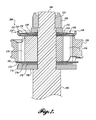
- FIG. 10 is a front top perspective cutaway view of a ring shim of the damper valve assembly of FIG. 1 .
- the present application may include references to directions, such as “forward,” “rearward,” “front,” “rear,” “upward,” “downward,” “top,” “bottom,” “right hand,” “left hand,” “lateral,” “medial,” “in,” “out,” “extended,” etc. These references, and other similar references in the present application, are only to assist in helping describe and to understand the particular embodiment and are not intended to limit the present disclosure to these directions or locations.
- the present application may also reference quantities and numbers. Unless specifically stated, such quantities and numbers are not to be considered restrictive, but exemplary of the possible quantities or numbers associated with the present application. Also in this regard, the present application may use the term “plurality” to reference a quantity or number.
- Embodiments of the present disclosure are generally directed to adjusting the damping characteristics of a damper using shim configurations in conjunction with a piston.
- Embodiments of the dampers disclosed herein are suitable to attach to any components between which a damping force is desired (e.g., a vehicle suspension system).
- Embodiments disclosed herein use symmetry, where applicable, for clarity and convenience; however, the use of symmetry (e.g., left to right, front and rear, and/or top and bottom, etc.) should not be construed as limiting the scope of the disclosure to symmetric parts, as the present disclosure also contemplates “handed” parts in locations where symmetric parts are illustrated and described.
- a damper having a shimmed piston generally includes an elongate shaft with a piston fixed at one end. As the shaft travels in an axial direction, the piston travels through hydraulic damping fluid in a central bore of the damper body.
- the piston generally includes apertures (referred to as “valves”) extending through the piston and sized such that the valves provide fluidic resistance as the piston travels through the hydraulic damping fluid.
- the movement of the piston through the hydraulic damping fluid provides a force counter to the movement of the shaft, resulting in a damping effect of the motion of the shaft.
- the force provided by the hydraulic damping fluid is dependent on a range of factors, including hydraulic damping fluid viscosity, temperature, pressure, purity, composition; shaft velocity; and piston aperture size and shape, among other factors.
- valves in the piston are configured such that only certain of the valves are intended for hydraulic damping fluid flow during a compression stroke of the damper (insertion of the shaft within the damper body), and certain other of the valves are intended for hydraulic damping fluid flow during a rebound stroke of a damper (extension of the shaft from the damper body).
- the valves can be tailored or “tuned” to exhibit the desired damping characteristics depending on the intended use of the damper. If shims were not used with the piston, an excess of hydraulic damping fluid would simultaneously flow through all of the valves, and would provide a low damping effect.
- a shim stack is used to overlap the valve openings such that the flow of hydraulic damping fluid is only allowed in one direction in the valves intended for the compression stroke (compression valves), and in the opposite direction in the valves intended for the rebound stroke (rebound valves).
- the hydraulic damping fluid flows through the valve and exerts a force on the shim stack such that the shim stack deflects away from the valve and allows the flow of hydraulic damping fluid. Since an opposing shim stack is overlapping the other set of valves, flow is contained within only the intended valves when the shaft of the damper is moving in either direction.
- a shim stack used in conventional dampers has a wide variety of configurations.
- the shims are arranged such that they provide a certain resistance to the flow of the hydraulic damping fluid through the valves.
- the valves have a shape and size to correspond to desired flow characteristics of the piston.
- the compression and rebound valves are shown with one representative embodiment; however, in other embodiments, any suitable piston valve configuration is used in conjunction with the ring shim of the present disclosure.
- the characteristics of the damper can be controlled independently in compression and rebound operation. Often, adjustment to the compression and rebound is achieved independently and allows tailoring of the damper to the specific application.
- a high damping effect on the compression stroke can lead to a harsher ride, but can assist in maintaining stability for high-speed operation.
- the rebound stroke having a high damping effect can lead to a ratcheting effect of the suspension where the damper does not allow quick enough movement to return to an optimal setting after encountering a series of compressions. Therefore, a damper must be tailored to a specific application while taking into account, weight, terrain, spring forces, performance expectations, ride quality, etc.
- a damper typically has different damping effect depending on the speed of the shaft.
- slow speed damping can be controlled using different valves than the valves intended for high speed damping.
- the slow speed damping may include rolling over the crest of a hill, or the compression of the suspension as the vehicle dives while braking or rotates into a corner.
- the high speed damping may include hitting a bump at speed or driving on an uneven road surface.
- a damper will be designed to exhibit different damping characteristics for slow and high speed damping.
- preload of the shim stack can be used to tailor of damping characteristics.
- Preloading the shim stack involves the shims being slightly deflected in a neutral state by the configuration of the assembly of the shaft and piston.
- a preload of the shim stack can limit the opening of the shims (deflection) to only certain higher speeds of the shaft of the damper.
- the preload may prevent the shims from deflecting during the aforementioned slow speed damping, while allowing high speed damping.
- the performance of a vehicle may improve by providing a higher damping force during slow speed damping, and a lower damping force during high speed damping.
- the cornering (slower speed damping) of the vehicle may improve by keeping the chassis in a relatively neutral position, while encountering a sharp bump in that corner (high speed damping) allows the damper to deflect quickly with the bump and improve the contact of the tire with the road surface, increasing grip.
- a first exemplary embodiment of a shimmed piston assembly 100 suitable for use with a damper (not shown) is depicted.
- the shimmed piston assembly 100 is shown coupled to one end of a shaft 102 having a distal end 104 and a proximal end 106 .
- the distal end 104 of the shaft 102 is typically configured to couple with a mounting joint (not shown) to attach to a component for which a damping effect is desired.
- the proximal end 106 of the shaft 102 is configured to carry the shimmed piston assembly 100 with a necked section 112 of the shaft 102 .
- the shimmed piston assembly 100 is secured to the necked section 112 with a fastener assembly, such as a nut 150 , interfacing a threaded section 114 of the shaft 102 (see FIG. 4 ), and an upper washer 152 disposed between the nut 150 and the shimmed piston assembly 100 .
- a fastener assembly such as a nut 150 , interfacing a threaded section 114 of the shaft 102 (see FIG. 4 ), and an upper washer 152 disposed between the nut 150 and the shimmed piston assembly 100 .
- the nut 150 is preferably a locking nut such that movement of the shaft 102 does not allow the nut 150 to loosen over time.
- the nut 150 is coupled to the threaded section 114 using a locking fluid (not shown).
- the nut 150 is installed with a sufficient torque such that the nut 150 does not loosen during use of the damper.
- the shimmed piston assembly 100 is secured distal to the nut 150 using a primary washer 108 , which is configured to interface a shoulder at a transition between the necked section 112 and the shaft 102 to prevent sliding movement of the shimmed piston assembly 100 along the shaft 102 .
- the shimmed piston assembly 100 is coupled to any suitable location along the shaft 102 using any suitable coupling.
- one embodiment of the shimmed piston assembly 100 includes a piston 120 having rebound valves 126 and compression valves 128 extending therethrough.
- the rebound valves 126 are configured to allow the flow of hydraulic damping fluid during the rebound stroke (extension) of the shaft 102 .
- the compression valves 128 are configured to allow the flow of hydraulic damping fluid during the compression stroke (insertion) of the shaft 102 .
- any suitable valve configuration can be used with the embodiments of the present disclosure.
- the rebound valves 126 of the piston 120 interface a rebound shim assembly 110 disposed between the piston 120 and the upper washer 152 .
- the rebound shim assembly 110 is configured to overlap the rebound valves 126 such that flow of the hydraulic damping fluid is prevented during the compression stroke, and limited by the rebound shim assembly 110 during the rebound stroke.
- the rebound shim assembly 110 must necessarily deflect away from the piston 120 to incrementally open the passageway through the rebound valves 126 .
- the rebound shim assembly 110 completely overlaps the rebound valves 126 .
- the rebound shim assembly 110 overlaps a portion of the rebound valves 126 .
- the compression valves 128 of the piston 120 interface a compression shim assembly 180 disposed between the piston 120 and the primary washer 108 .
- the compression shim assembly 180 is configured to overlap the compression valves 128 such that flow of the hydraulic damping fluid is prevented during the rebound stroke, and limited by the compression shim assembly 180 during the compression stroke.
- the compression shim assembly 180 must necessarily deflect away from the piston 120 to incrementally open the passageway through the compression valves 128 .
- the compression shim assembly 180 completely overlaps the compression valves 128 .
- the compression shim assembly 180 overlaps a portion of the rebound valves 128 .
- Each of the rebound and compression shim assemblies 110 and 180 includes various components configured to affect the damping characteristics. Although representative embodiments are illustrated and described herein, it should be appreciated that any shim configuration is suitable for use with the present disclosure, and the advantages are not limited to the configurations illustrated and described herein.
- a rebound overlap shim 122 is configured to closely interface the piston 120 and overlap the rebound valves 126 as described above.
- the rebound overlap shim 122 provides the initial sealing component to prevent flow of the hydraulic damping fluid through the rebound valves 126 during the compression stroke of the shaft 102 .
- the interface of the rebound overlap shim 122 with the rebound valves 126 of the piston 120 is shown in FIG. 4 .
- the rebound overlap shim 122 overlaps the rebound valve 126 to prevent the flow of hydraulic damping fluid while the piston travels in the direction of the compression stroke (i.e., travel in a direction leading with the proximal end 106 of the shaft 102 ).
- Adjacent to the rebound overlap shim 122 is assembled at least one rebound preload adjustment washer 124 , which will be described in greater detail below.
- a rebound preload ring shim 130 is adjacent to the rebound overlap shim 122 .
- a rebound shim stack assembly 140 is disposed adjacent a radially inward annular projection 166 (see FIG. 10 ) of the rebound preload ring shim 130 .
- the rebound shim stack assembly 140 interfaces the radially inward annular projection 166 in an axial direction, and the necked section 112 of the shaft 102 in a radial direction at the inner aperture of each shim in the rebound shim stack assembly 140 .
- the rebound shim stack assembly 140 is illustrated as having a first rebound shim 132 , a second rebound shim 134 , a third rebound shim 136 , and a fourth rebound shim 138 , each shim in order of descending outer radius away from the rebound preload ring shim 130 .
- the first rebound shim 132 is radially sized to interface a circumferential projection 168 (see FIG. 10 ) of the rebound preload ring shim 130 .
- the stacked configuration of the rebound shim assembly 110 includes a gap between the first rebound shim 132 and the rebound preload adjustment washer 124 .
- the aforementioned gap is reduced by tightening the nut 150 during assembly, such that the first rebound shim 132 and the rebound preload adjustment washer 124 abut (see FIG. 5 ).
- the rebound shim stack assembly 140 is deflected as a result of drawing the first rebound shim 132 to the rebound preload adjustment washer 124 during tightening of the nut 150 .
- the amount of preload on the rebound shim stack assembly 140 can be controlled by the width of the gap.
- all of the components of the rebound shim assembly 110 deflect away from the piston 120 to allow hydraulic damping fluid flow through the rebound valves 126 .
- the rebound preload ring shim 130 includes the radially inward annular projection 166 having a ring shim axial thickness 160 , and the circumferential projection 168 having a ring shim height 164 .
- the rebound preload ring shim 130 also has a diameter 162 .
- the diameter 162 is sized such that the first rebound shim 132 will fit within the aperture of the circumferential projection 168 and abut an upper surface of the radially inward annular projection 166 .
- the gap between the first rebound shim 132 and the rebound preload adjustment washer 124 is controlled by the ring shim axial thickness 160 and the thickness of the rebound preload adjustment washer 124 .
- the ring shim axial thickness 160 can be 0.040′′ and the rebound preload adjustment washer 124 can be 0.020′′ to arrive at the desired 0.020′′ preload gap distance.
- any combination of ring shim axial thickness 160 and thickness of the rebound preload adjustment washer 124 is used to suitably control the preload gap distance.
- the rebound preload adjustment washer 124 is omitted, or more than one rebound preload adjustment washer 124 is used with the configuration. In embodiments where the rebound preload adjustment washer 124 is omitted, the first rebound shim 132 directly abuts the rebound overlap shim 122 upon drawing the components together with the nut 150 .
- One advantage of assembling the rebound shim assembly 110 with the rebound preload adjustment washer 124 and the rebound preload ring shim 130 is to limit the need for rebound preload ring shims 130 with a wide variety of ring shim axial thicknesses 160 . In this regard, fewer part variations can be manufactured and adapted to fit a wider range of preload settings.
- the rebound preload ring shim 130 is substantially axially centered with respect to the shaft 102 .
- the circumferential projection 168 additionally provides structural rigidity to the rebound preload ring shim 130 for further consistency in preload settings and damping characteristics of the assembly.
- a compression overlap shim 182 is configured to closely interface the piston 120 and overlap the compression valves 128 as described above.
- the compression overlap shim 182 provides the initial sealing component to prevent flow of the hydraulic damping fluid through the compression valves 128 during the rebound stroke of the shaft 102 .
- the interface of the compression overlap shim 182 with the compression valves 128 of the piston 120 is shown in FIG. 4 .
- the compression overlap shim 182 overlaps the compression valve 128 to prevent the flow of hydraulic damping fluid while the piston travels in the direction of the rebound stroke (i.e., travel in a direction leading with the distal end 104 of the shaft 102 ).
- a compression preload ring shim 170 is adjacent to the compression overlap shim 182 .
- a compression shim stack assembly 190 is disposed adjacent a radially inward annular projection (not shown, but substantially similar to 166 in FIG. 10 ) of the compression preload ring shim 170 .
- the compression shim stack assembly 190 interfaces the radially inward annular projection in an axial direction, and the necked section 112 of the shaft 102 in a radial direction at the inner aperture of each shim in the compression shim stack assembly 190 .
- the compression shim stack assembly 190 is illustrated as having a first compression shim 172 , a second compression shim 174 , a third compression shim 176 , and a fourth compression shim 178 , each shim in order of descending outer radius away from the compression preload ring shim 170 .
- the first compression shim 172 is radially sized to interface a circumferential projection (not shown, but substantially similar to 168 in FIG. 10 ) of the compression preload ring shim 170 .
- the stacked configuration of the compression shim assembly 180 contains a gap between the first compression shim 172 and the second compression preload adjustment washer 186 .
- the aforementioned gap is drawn together by tightening the nut 150 during assembly, such that the first compression shim 172 and the second compression preload adjustment washer 186 abut (see FIG. 5 ).
- the compression shim stack assembly 190 is deflected as a result of drawing the first compression shim 172 to the second compression preload adjustment washer 186 during tightening of the nut 150 .
- the amount of preload on the compression shim stack assembly 190 can be controlled by the width of the gap.
- the compression preload ring shim 170 is substantially similar to the rebound preload ring shim 130 shown in FIG. 10 , including the radially inward annular projection having a ring shim axial thickness, and the circumferential projection having a ring shim height.
- the compression preload ring shim 130 also has a diameter sized such that the first compression shim 172 fits within the aperture of the circumferential projection and abuts an upper surface of the radially inward annular projection. As can be appreciated by the configuration shown in FIG.
- the gap between the first compression shim 172 and the second compression preload adjustment washer 186 is controlled by the ring shim axial thickness and the thickness of the first and second compression preload adjustment washers 184 and 186 .
- the ring shim axial thickness can be 0.040′′ and the first compression preload adjustment washer 184 can be 0.020′′ in thickness, with the second compression preload adjustment washer 186 at a thickness of 0.010′′ to arrive at the desired 0.010′′ preload gap distance.
- any combination of ring shim axial thickness and thickness of the first and second compression preload adjustment washers 184 and 186 is used to suitably control the preload gap distance.
- first and second compression preload adjustment washers 184 and 186 are omitted, a single compression preload adjustment washer is used, or more than two compression preload adjustment washers are used with the configuration. In embodiments where the first and second compression preload adjustment washers 184 and 186 are omitted, the first compression shim 172 directly abuts the compression overlap shim 182 upon drawing the components together with the nut 150 .
- one advantage of assembling the compression shim assembly 180 with the first and second compression preload adjustment washers 184 and 186 , and the compression preload ring shim 170 is to limit the need for compression preload ring shims 170 with a wide variety of ring shim axial thicknesses. In this regard, fewer part variations can be manufactured and adapted to fit a wider range of preload settings.
- the compression preload ring shim 170 is substantially axially centered with respect to the shaft 102 .
- the circumferential projection of the compression preload ring shim 170 additionally provides structural rigidity to the compression preload ring shim 130 for further consistency in preload settings and damping characteristics of the assembly.
- a preload ring shim is used in both the rebound shim assembly 110 and the compression shim assembly 180 ; however, in other embodiments, a preload ring shim is suitably used on only the rebound shim assembly 110 (see FIGS. 6 and 7 ), or, conversely, a preload ring shim is suitably used on only the compression shim assembly 180 (see FIGS. 8 and 9 ). In the embodiments shown in FIGS. 6 and 7 where the compression preload ring shim 180 is omitted, the shim assembly is shown without a preload ( FIG.
Abstract
Description
Claims (19)
Priority Applications (3)
| Application Number | Priority Date | Filing Date | Title |
|---|---|---|---|
| US15/338,131 US10344820B2 (en) | 2016-10-28 | 2016-10-28 | Digressive valve for a damper |
| CA2983507A CA2983507C (en) | 2016-10-28 | 2017-10-24 | Digressive valve for a damper |
| US16/415,947 US11002334B2 (en) | 2016-10-28 | 2019-05-17 | Digressive valve for a damper |
Applications Claiming Priority (1)
| Application Number | Priority Date | Filing Date | Title |
|---|---|---|---|
| US15/338,131 US10344820B2 (en) | 2016-10-28 | 2016-10-28 | Digressive valve for a damper |
Related Child Applications (1)
| Application Number | Title | Priority Date | Filing Date |
|---|---|---|---|
| US16/415,947 Continuation-In-Part US11002334B2 (en) | 2016-10-28 | 2019-05-17 | Digressive valve for a damper |
Publications (2)
| Publication Number | Publication Date |
|---|---|
| US20180119768A1 US20180119768A1 (en) | 2018-05-03 |
| US10344820B2 true US10344820B2 (en) | 2019-07-09 |
Family
ID=62017664
Family Applications (1)
| Application Number | Title | Priority Date | Filing Date |
|---|---|---|---|
| US15/338,131 Expired - Fee Related US10344820B2 (en) | 2016-10-28 | 2016-10-28 | Digressive valve for a damper |
Country Status (2)
| Country | Link |
|---|---|
| US (1) | US10344820B2 (en) |
| CA (1) | CA2983507C (en) |
Cited By (1)
| Publication number | Priority date | Publication date | Assignee | Title |
|---|---|---|---|---|
| US20220196106A1 (en) * | 2020-12-23 | 2022-06-23 | Ktm Ag | Valve arrangement for a vibration damper |
Families Citing this family (6)
| Publication number | Priority date | Publication date | Assignee | Title |
|---|---|---|---|---|
| USD872837S1 (en) | 2017-08-28 | 2020-01-14 | Qa1 Precision Products, Inc. | Bleed needle |
| USD866408S1 (en) | 2017-08-28 | 2019-11-12 | Qa1 Precision Products, Inc. | Shock absorber |
| US11105390B2 (en) | 2017-08-28 | 2021-08-31 | Qa1 Precision Products, Inc. | Shock absorber with dry valving |
| US11085502B2 (en) | 2017-08-28 | 2021-08-10 | Qa1 Precision Products, Inc. | Bleed needle for a hydraulic system |
| USD869259S1 (en) * | 2017-08-28 | 2019-12-10 | Qa1 Precision Products, Inc. | Valve component |
| CN113586643B (en) * | 2020-04-30 | 2022-09-06 | 比亚迪股份有限公司 | Shock absorber and vehicle |
Citations (21)
| Publication number | Priority date | Publication date | Assignee | Title |
|---|---|---|---|---|
| US4197929A (en) | 1978-01-13 | 1980-04-15 | Kayaba Kogyo K.K. | Device for producing damping force in hydraulic shock absorbers |
| US4972929A (en) | 1989-06-07 | 1990-11-27 | Lord Corporation | Bidirectional dual disc valve assembly |
| US5529398A (en) | 1994-12-23 | 1996-06-25 | Bosley; Robert W. | Compliant foil hydrodynamic fluid film thrust bearing |
| US5921360A (en) | 1997-06-05 | 1999-07-13 | General Motors Corporation | Digressive damper valve |
| US6260678B1 (en) | 1999-08-31 | 2001-07-17 | Delphi Technologies, Inc. | Digressive base valve for automotive damper |
| US20020063023A1 (en) | 2000-11-30 | 2002-05-30 | Delphi Technologies Inc. | Digressive piston compression valve |
| US6581734B2 (en) | 2001-05-21 | 2003-06-24 | Zf Sachs Ag | Damping valve for a shock absorber |
| US6655512B2 (en) | 2000-12-19 | 2003-12-02 | Delphi Technologies, Inc. | Variable area low speed orifice in a vehicle damper |
| US20040166764A1 (en) | 2003-02-15 | 2004-08-26 | Stark Steven Patrick | Flexible flying disc |
| US20050056505A1 (en) * | 2003-09-15 | 2005-03-17 | Stefan Deferme | Monotube piston valving system with selective bleed |
| US20060283676A1 (en) * | 2005-06-21 | 2006-12-21 | Stefan Deferme | Four-piece piston |
| US7238112B2 (en) | 2003-07-07 | 2007-07-03 | Borgwarner. Inc. | Torsional-vibration damper |
| US20090057080A1 (en) * | 2007-08-30 | 2009-03-05 | Tenneco Automotive Operating Company, Inc. | Shock absorber having a full displacement valve assembly |
| US7980368B2 (en) | 2007-02-02 | 2011-07-19 | Mando Corporation | Damping force variable shock absorber |
| US8517154B2 (en) | 2010-02-26 | 2013-08-27 | Hitachi Automotive Systems, Ltd. | Shock absorber |
| US20130319804A1 (en) * | 2012-06-04 | 2013-12-05 | Tenneco Automotive Operating Company Inc. | Shock absorber with four chambers |
| US20150041264A1 (en) * | 2012-04-23 | 2015-02-12 | Beijingwest Industries, Co., Ltd. | Hydraulic suspension damper with a floating disc valve |
| US20150159724A1 (en) | 2012-06-27 | 2015-06-11 | Kayaba Industry Co., Ltd. | Damping valve |
| WO2015158495A1 (en) | 2014-04-17 | 2015-10-22 | Zf Friedrichshafen Ag | Adjustable damping valve device |
| US20150316118A1 (en) | 2012-10-04 | 2015-11-05 | Thyssenkrupp Bilstein Gmbh | Damping valve for a shock absorber |
| US20160017914A1 (en) | 2013-03-06 | 2016-01-21 | Aktiebolaget Skf | Method of setting bearing preload |
-
2016
- 2016-10-28 US US15/338,131 patent/US10344820B2/en not_active Expired - Fee Related
-
2017
- 2017-10-24 CA CA2983507A patent/CA2983507C/en active Active
Patent Citations (21)
| Publication number | Priority date | Publication date | Assignee | Title |
|---|---|---|---|---|
| US4197929A (en) | 1978-01-13 | 1980-04-15 | Kayaba Kogyo K.K. | Device for producing damping force in hydraulic shock absorbers |
| US4972929A (en) | 1989-06-07 | 1990-11-27 | Lord Corporation | Bidirectional dual disc valve assembly |
| US5529398A (en) | 1994-12-23 | 1996-06-25 | Bosley; Robert W. | Compliant foil hydrodynamic fluid film thrust bearing |
| US5921360A (en) | 1997-06-05 | 1999-07-13 | General Motors Corporation | Digressive damper valve |
| US6260678B1 (en) | 1999-08-31 | 2001-07-17 | Delphi Technologies, Inc. | Digressive base valve for automotive damper |
| US20020063023A1 (en) | 2000-11-30 | 2002-05-30 | Delphi Technologies Inc. | Digressive piston compression valve |
| US6655512B2 (en) | 2000-12-19 | 2003-12-02 | Delphi Technologies, Inc. | Variable area low speed orifice in a vehicle damper |
| US6581734B2 (en) | 2001-05-21 | 2003-06-24 | Zf Sachs Ag | Damping valve for a shock absorber |
| US20040166764A1 (en) | 2003-02-15 | 2004-08-26 | Stark Steven Patrick | Flexible flying disc |
| US7238112B2 (en) | 2003-07-07 | 2007-07-03 | Borgwarner. Inc. | Torsional-vibration damper |
| US20050056505A1 (en) * | 2003-09-15 | 2005-03-17 | Stefan Deferme | Monotube piston valving system with selective bleed |
| US20060283676A1 (en) * | 2005-06-21 | 2006-12-21 | Stefan Deferme | Four-piece piston |
| US7980368B2 (en) | 2007-02-02 | 2011-07-19 | Mando Corporation | Damping force variable shock absorber |
| US20090057080A1 (en) * | 2007-08-30 | 2009-03-05 | Tenneco Automotive Operating Company, Inc. | Shock absorber having a full displacement valve assembly |
| US8517154B2 (en) | 2010-02-26 | 2013-08-27 | Hitachi Automotive Systems, Ltd. | Shock absorber |
| US20150041264A1 (en) * | 2012-04-23 | 2015-02-12 | Beijingwest Industries, Co., Ltd. | Hydraulic suspension damper with a floating disc valve |
| US20130319804A1 (en) * | 2012-06-04 | 2013-12-05 | Tenneco Automotive Operating Company Inc. | Shock absorber with four chambers |
| US20150159724A1 (en) | 2012-06-27 | 2015-06-11 | Kayaba Industry Co., Ltd. | Damping valve |
| US20150316118A1 (en) | 2012-10-04 | 2015-11-05 | Thyssenkrupp Bilstein Gmbh | Damping valve for a shock absorber |
| US20160017914A1 (en) | 2013-03-06 | 2016-01-21 | Aktiebolaget Skf | Method of setting bearing preload |
| WO2015158495A1 (en) | 2014-04-17 | 2015-10-22 | Zf Friedrichshafen Ag | Adjustable damping valve device |
Cited By (1)
| Publication number | Priority date | Publication date | Assignee | Title |
|---|---|---|---|---|
| US20220196106A1 (en) * | 2020-12-23 | 2022-06-23 | Ktm Ag | Valve arrangement for a vibration damper |
Also Published As
| Publication number | Publication date |
|---|---|
| US20180119768A1 (en) | 2018-05-03 |
| CA2983507C (en) | 2021-07-20 |
| CA2983507A1 (en) | 2018-04-28 |
Similar Documents
| Publication | Publication Date | Title |
|---|---|---|
| CA2983507C (en) | Digressive valve for a damper | |
| US9605726B2 (en) | Secondary dampening assembly for shock absorber | |
| US11002334B2 (en) | Digressive valve for a damper | |
| US8616351B2 (en) | Damper with digital valve | |
| US7703586B2 (en) | Four-piece piston | |
| US8408569B2 (en) | Damper tube reinforcement sleeve | |
| US8434772B2 (en) | Damper tube reinforcement sleeve | |
| US8794407B2 (en) | Velocity progressive valving | |
| US8997953B2 (en) | Shock absorber having a full displacement valve assembly | |
| US9739330B2 (en) | Double tube damper with structural pressure tube | |
| US9500251B2 (en) | Shock absorber having orifice check disc | |
| US10145439B2 (en) | Variable radius spring disc for vehicle shock absorber | |
| DE112014001146T5 (en) | Bumper bumper nose support element for a shock absorber | |
| US9080629B2 (en) | Multi-tuneable degressive valve | |
| US20190329623A1 (en) | Damper With Internal Hydraulic Stop | |
| US8627933B2 (en) | Two stage valve and hydraulic damped valve | |
| US11091001B2 (en) | Base valve assembly for damper | |
| US6230858B1 (en) | Internally slotted orifice disc for low speed control in automotive dampers | |
| US20230332662A1 (en) | Damper assembly | |
| US9038790B2 (en) | Frequency sensitive shock absorber | |
| US10774897B2 (en) | Electronic damper control | |
| US11668365B2 (en) | Valve body for a damper |
Legal Events
| Date | Code | Title | Description |
|---|---|---|---|
| AS | Assignment |
Owner name: TERAFLEX, INC., UTAH Free format text: ASSIGNMENT OF ASSIGNORS INTEREST;ASSIGNOR:COX, CHRISTOPHER PAUL;REEL/FRAME:040163/0690 Effective date: 20161028 |
|
| AS | Assignment |
Owner name: MF IP HOLDING, LLC, UTAH Free format text: ASSIGNMENT OF ASSIGNORS INTEREST;ASSIGNOR:TERAFLEX, INC.;REEL/FRAME:047993/0636 Effective date: 20181226 |
|
| STPP | Information on status: patent application and granting procedure in general |
Free format text: NOTICE OF ALLOWANCE MAILED -- APPLICATION RECEIVED IN OFFICE OF PUBLICATIONS |
|
| STPP | Information on status: patent application and granting procedure in general |
Free format text: PUBLICATIONS -- ISSUE FEE PAYMENT VERIFIED |
|
| STCF | Information on status: patent grant |
Free format text: PATENTED CASE |
|
| AS | Assignment |
Owner name: WELLS FARGO BANK, NATIONAL ASSOCIATION, AS COLLATERAL AGENT, CALIFORNIA Free format text: SECURITY INTEREST;ASSIGNORS:43 RACING, LLC;THE RETROFIT SOURCE, LLC;MORIMOTO LIGHTING LLC;AND OTHERS;REEL/FRAME:060527/0727 Effective date: 20220715 |
|
| FEPP | Fee payment procedure |
Free format text: MAINTENANCE FEE REMINDER MAILED (ORIGINAL EVENT CODE: REM.); ENTITY STATUS OF PATENT OWNER: SMALL ENTITY |
|
| LAPS | Lapse for failure to pay maintenance fees |
Free format text: PATENT EXPIRED FOR FAILURE TO PAY MAINTENANCE FEES (ORIGINAL EVENT CODE: EXP.); ENTITY STATUS OF PATENT OWNER: SMALL ENTITY |
|
| STCH | Information on status: patent discontinuation |
Free format text: PATENT EXPIRED DUE TO NONPAYMENT OF MAINTENANCE FEES UNDER 37 CFR 1.362 |
|
| FP | Lapsed due to failure to pay maintenance fee |
Effective date: 20230709 |
|
| AS | Assignment |
Owner name: DEUTSCHE BANK AG NEW YORK BRANCH, AS COLLATERAL AGENT, NEW YORK Free format text: FIRST LIEN INTELLECTUAL PROPERTY SECURITY AGREEMENT;ASSIGNORS:43 RACING, LLC;HOONIGAN INDUSTRIES, LLC;THE RETROFIT SOURCE, LLC;AND OTHERS;REEL/FRAME:066341/0169 Effective date: 20220715 |