EP1662276B1 - Linse mit veränderbarer Brennweite - Google Patents
Linse mit veränderbarer Brennweite Download PDFInfo
- Publication number
- EP1662276B1 EP1662276B1 EP05111183A EP05111183A EP1662276B1 EP 1662276 B1 EP1662276 B1 EP 1662276B1 EP 05111183 A EP05111183 A EP 05111183A EP 05111183 A EP05111183 A EP 05111183A EP 1662276 B1 EP1662276 B1 EP 1662276B1
- Authority
- EP
- European Patent Office
- Prior art keywords
- lens
- cap
- side wall
- cylindrical
- liquids
- Prior art date
- Legal status (The legal status is an assumption and is not a legal conclusion. Google has not performed a legal analysis and makes no representation as to the accuracy of the status listed.)
- Expired - Lifetime
Links
Images

Classifications
-
- G—PHYSICS
- G02—OPTICS
- G02B—OPTICAL ELEMENTS, SYSTEMS OR APPARATUS
- G02B26/00—Optical devices or arrangements for the control of light using movable or deformable optical elements
- G02B26/004—Optical devices or arrangements for the control of light using movable or deformable optical elements based on a displacement or a deformation of a fluid
- G02B26/005—Optical devices or arrangements for the control of light using movable or deformable optical elements based on a displacement or a deformation of a fluid based on electrowetting
-
- G—PHYSICS
- G02—OPTICS
- G02B—OPTICAL ELEMENTS, SYSTEMS OR APPARATUS
- G02B3/00—Simple or compound lenses
- G02B3/12—Fluid-filled or evacuated lenses
-
- G—PHYSICS
- G02—OPTICS
- G02B—OPTICAL ELEMENTS, SYSTEMS OR APPARATUS
- G02B3/00—Simple or compound lenses
- G02B3/12—Fluid-filled or evacuated lenses
- G02B3/14—Fluid-filled or evacuated lenses of variable focal length
Definitions
- the present invention relates to lenses of variable focal length and more particularly to such lenses employing the deformation of a drop of liquid through electrowetting phenomena.
- FIG. 1 A cell is defined by two transparent insulating plates 1 and 2 and side walls (not depicted).
- the lower plate 2 which is non-planar, comprises a conical or cylindrical depression or recess 3, of axis ⁇ , which contains a drop of an insulating liquid 4.
- the remainder of the cell is filled with an electrically conductive liquid 5, non-miscible with the insulating liquid, with a different refractive index and essentially the same density.
- An annular electrode 7 open facing the recess 3 is positioned on the rear face of the lower plate 2.
- Another electrode 8 is in contact with the conductive liquid 5.
- the conductive liquid is generally an aqueous liquid and the insulating liquid an oily liquid.
- the mount for the lens formed by the transparent plates 1, 2 and the side walls connecting the transparent plates generally constitutes a rigid structure.
- the pressure of the liquids in the lens mount may increase substantially, for example during operations of assembling the parts that make up the mount or, once the mount has been assembled, when the temperature of the liquids of the lens, which have coefficients of expansion higher than the coefficients of expansion of the materials of which the mount is made, increases.
- the present invention is aimed at a lens of variable focal length the optical properties of which are not disturbed during assembly and use of the lens by a variation in the pressure of the liquids contained within the lens.
- the invention is also aimed at a method for manufacturing such lens of variable focal length.
- International patent application WO 2004/099847 discloses a lens of variable focal length containing liquids and comprising elastic means capable of deforming in response to a change in pressure of the liquids.
- the present invention provides according to a first aspect, a lens of variable focal length with an optical axis ⁇ according to Claim 1. According to a further aspect, the invention provides a method according to claim 18 of manufacturing a lens of variable focal length.
- a structure of a lens with an elastic means capable of deforming preferably in response to variations in the pressure of the liquids contained in the lens and the deformation of which has little or no influence on the optical properties of the lens.
- FIG. 2 depicts an exemplary embodiment of a mount for a lens of variable focal length according to the invention, at an intermediate step in the method of manufacturing the mount.
- the mount for a lens of variable focal length 10 according to the invention is made up of an upper part 12 and of a lower part 14 which are produced separately from one another and which, when assembled, define an internal volume 15 containing the insulating and conducting liquids (not depicted).
- the lower part 14 comprises a body 16 having symmetry of revolution about the axis ⁇ , for example made of steel, comprising a base 17 through which there passes a central opening 18, and continued by a cylindrical lateral portion 20 which ends in a frustoconical rim 22.
- the base 17 of the body 16 comprises a wavy portion 23 exhibiting symmetry of revolution about the axis ⁇ and of which the cross section on a plane containing the axis ⁇ has the shape of an "S". More generally, portion 23 comprises a non-linear portion capable of deforming in response to a change in pressure inside the lens.
- a cylindrical plate 24 made of a transparent material, for example of glass, is fixed to the body 16, covering the opening 18 on the same side as the internal volume 15 of the mount 10, by a fixing material 22, for example a welding glass or any other type of adhesive.
- the upper part 12 of the mount 10 comprises a cap 30, through the central part of which there passes a cylindrical opening 32 and which is extended by a cylindrical side wall 34 the diameter of which is greater than the diameter of the cylindrical wall 20 of the body 16.
- the cap 30 comprises an elastic portion 36 provided between the opening 32 and the cylindrical side wall 34.
- the elastic portion 36 consists of a wavy portion exhibiting symmetry of revolution about the axis ⁇ and of which the cross section on a plane containing the axis ⁇ has the shape of an "S". More generally, the elastic portion 36 comprises a non-linear portion capable of deforming in response to a change in pressure inside the lens.
- the cap comprises an upper wall (31) connected to the transparent plate and the cylindrical side wall 34 and the upper wall comprises bent portions 36 with symmetry of revolution about the optical axis ( ⁇ ) of the lens.
- the cap is made of a stamped metal, e.g. in stainless steel.
- the thickness of the upper wall of the cap will depend on the expected variations of volume to compensate for the effects of expansion of the liquids. For example, a typical thickness of about 0.1 to 0.25 mm has shown good results for lenses whose outer diameters is below 20 mm.
- a cylindrical plate 38 made of a transparent material, for example of glass, is fixed to the cap 30, covering the opening 32 on the same side as the internal volume 15 of the mount 10, by a fixing material 40, for example glass or an adhesive.
- the cylindrical plate 38 is used as a window for covering the opening 32.
- the window can be a fixed lens made of a transparent optical material.
- An intermediate piece 42 is positioned at the base 17 of the body 16 on the same side as the internal volume 15.
- the intermediate piece 42 comprises a planar face 44 resting against the glass plate 24, and through it there passes an opening 46 defining a conical surface 48 adjacent to the glass plate 24.
- the intermediate piece 42 is, for example, made of stainless steel and is covered with an insulating layer at least on its faces in contact with the conducting liquid contained in the mount 10. During use of the lens, the edge of the interface between the conducting liquid and the insulating liquid both contained in the internal volume 15 moves along the frustoconical surface 48, the insulating liquid wetting the glass plate 24.
- the roughness of the conical surface 48 is defined by a roughness parameter Ra (arithmetic mean deviation) of less than 0.1 ⁇ m in order to have good control over the movements of the interface between the two liquids.
- the production of the conical surface 48 may involve a surface-finishing process of the abrasion polishing (tribofinishing), electrolytic polishing or diamond-point machining type.
- a gasket 50 is positioned between the body 16 and the cap 30 at the peripheral of the body 16 and of the cap 30.
- the gasket 50 comprises a toric portion 52 extended via a skirt portion 54.
- the gasket 50 is made of fluorosilicone or of ethylene propylene diene (EPDM) terpolymer, or of FKM which is the standardized term for a fluorinated polymer of the Viton type, Viton being a trade name of Dupont Dow Elastomers. More generally, the material of which the gasket 50 is made has a low absorption with respect to the liquids contained in the internal volume 15 of the mount 10, and this also contributes to the maintaining of the dielectric properties of the lens.
- the manufacture of a mount for a lens 10 begins with the separate manufacture of the upper 12 and lower 14 parts.
- the intermediate piece 42 is fixed to the body 16 for example as a crimped fitting in order to obtain good electrical contact between the intermediate piece 42 and the body 16.
- a sealing means is provided between the intermediate piece 42 and the glass plate 24. This may involve an earlier deposition of a layer of polymer on the planar face 44 of the intermediate piece 42 or on the glass plate 24, for example, of a curable adhesive.
- the gasket 50 is positioned at the body 16, the toric portion 52 resting against the intermediate piece 42 and the skirt portion 54 surrounding the cylindrical side wall 20 of the body 16.
- the frustoconical rim 22 of the body 16 assists with holding the gasket 50 on the body 16 before the cap 30 is fitted.
- the second part 14 associated with the gasket 50 is then immersed in the conducting liquid.
- a drop of the insulating liquid is placed in contact with the glass plate 24 and with the conical surface 48.
- the placement of the insulating liquid may be facilitated by providing, at the surface of the glass plate 24 intended to come into contact with the insulating liquid, a layer of a material which has a tendency to be preferentially wetted with the insulating liquid rather than with the conducting liquid.
- the cap 30 is then positioned on the gasket 50, the skirt portion 54 of the gasket 50 being interposed between the side wall 34 of the cap 30 and the side wall 20 of the body 16.
- the portion 52 of the gasket compressed between the cap and the intermediate piece 42 is toric but other shapes are possible for the portion 42.
- the section of said portion of the gasket could be rectangular or of any other shape.
- the last step in the manufacture of the mount 10 involves crimping the free rim of the side wall 34 of the cap 30 onto the body 16, at the same time compressing the toric portion 52 of the gasket 50 between the cap 30 and the intermediate piece 42.
- the cap 30 is crimped onto the body 16 by controlling the compression force exerted on the gasket 50.
- This then yields the structure as depicted in Figure 3 in which the lateral portion 34 of the cap 30 comprises an end portion 56 crimped onto the body 16.
- the skirt portion 54 of the gasket 50 is therefore compressed between the side wall 34 of the cap 30 and the side wall 20 of the body 16. Sealing of the internal volume 15 of the mount 10 is therefore afforded by the compression of the toric portion 52 and the compression of the skirt portion 54 of the gasket 50.
- the upper electrode of the lens consists of the cap 30 and the lower electrode consists of the body 16 in electrical contact with the intermediate piece 42.
- the gasket 50 therefore also provides electrical insulation of the cap 30 with respect to the body 16.
- the elastic means described previously corresponds to the elastic portion 36 of the cap 30. Specifically what happens is that if the pressure in the internal volume 15 of the mount 10 rises, the elastic portion 36 provided at the cap 30 deforms preferentially by comparison with the other parts of the mount 10. The stresses exerted on the transparent cylindrical plates 24, 38 are therefore lessened, thus avoiding any risk of the said plates 24, 38 deforming or rupturing. As the plates 24, 38 are not deformed, the optical power of the lens remains constant. There is therefore no variation in the focal length of the lens.
- the wavy portion 23 provided at the body 16 may also act as an elastic means, but to a lesser extent compared with the elastic portion 36, given that the thickness of the body 16 exceeds the thickness of the cap 30. However, the wavy portion 23 may deform in the event, for example, of substantial expansions of the liquids contained in the mount 10.
- the sealing layer provided between the glass plate 24 and the intermediate piece 42 and the layer encouraging the wetting with the insulating liquid over that of the conducting liquid, provided on the glass plate 24 on the same side as the internal volume 15, are one and the same layer.
- a protective layer based on organic materials.
- the intermediate piece 42 has been fitted at the body 16 in contact with the transparent plate 24, the whole is covered with an insulating layer on the side designed to face the internal volume 15 of the mount 10.
- the intermediate piece 42 and the body 16 form a single piece onto which the cap 30 is crimped.
- This single piece may comprise a shoulder to accept the transparent plate 24.
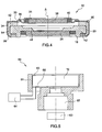
- Figure 4 shows a section of a further embodiment of the lens according to the invention.
- the lens 10 according to the invention comprises two transparent windows 24, 38 facing each other and parallel to one another, and delimiting, at least in part, an internal volume (15) containing two non-miscible liquids, with different optical indices, defining an optical interface (non represented on figure 4 ).
- the windows are transparent plates, made in an optical transparent material, e.g. in glass.
- at least one of the windows could be a fixed optical length, centred on the optical axis ( ⁇ ) of the variable focus lens.
- the lens comprises a cap 30 connected to one of the transparent windows 38 and comprising a first cylindrical side wall 34. It also comprises a body 16 having a symmetry of revolution, the axis of revolution defining the optical axis ( ⁇ ) of the lens.
- the body is connected to the other of the transparent windows (24) and comprises a second cylindrical side wall 20 of a diameter smaller than the diameter of the first cylindrical wall.
- the upper electrode consists of the cap 30 and the lower electrode consists of the body 16.
- a gasket 50 is provided to ensure the tightness of the lens mount. It is compressed between the first and second cylindrical side walls.
- the gasket comprises a skirt portion 54 compressed between the first and second cylindrical side walls and a portion 52 compressed between the cap and an intermediate part 42, forming in this example a single piece with the body, and comprising an opening defining a conical or cylindrical surface adjacent 48 where the interface between the two liquids is able to move.
- the lens further comprises an elastic means 36 capable of deforming in response to a change in pressure of the liquids.
- the elastic means comprise bent portions 36 formed on the upper wall 31 of the cap, said bent portions having symmetry of revolution about the optical axis ( ⁇ ) of the lens.
- the bent portions comprise at least one circular bend centred on the optical axis ( ⁇ ) of the lens.
- the cap can be made of a stamped metal, e.g. in stainless steel.
- the thickness of the upper wall of the cap will depend on the expected variations of volume to compensate for the effects of expansion of the liquids. For example, a typical thickness of about 0.1 to 0.25 mm has shown good results for lenses whose outer diameters is below 20 mm.
- the first side wall 34 comprises a rim 56 crimped onto the body 16 for the sealing of the cap onto the body.
- Other methods for sealing the cap onto the body are possible, for example it would be possible to glue the cap onto the body.
- the method for manufacturing the lens according to the invention as described in figure 4 can be similar to the method described previously.
- the method comprising the steps consisting in providing separately the cap 30 and the body 16, wherein windows 38 and 24 have been sealed to said cap and bodies. Then the gasket 50 is positioned between the first and second cylindrical side walls and the cap is positioned and sealed onto the body after the said internal volume has been filled with the two liquids.
- filling of the internal volume comprises immersing the body and the transparent window connected to it in a solution of the conducting liquid, placing a drop of insulating liquid in contact with the transparent window and positioning the gasket and the side wall of the cap, the body being kept immersed in the conducting solution.
- sealing the side wall of the cap onto the body is performed with the body being kept immersed in the conducting solution to avoid introducing any air bubbles in the lens.
- the cap is provided with bent portions having symmetry of revolution about the axis ( ⁇ ) to perform said elastic means.
- sealing of the cap onto the body is performed by crimping the side wall of the cap onto the body to get a very good mechanical strength of the mount.
- the present invention can be varied and modified in various ways that will be apparent to the person skilled in the art.
- the abovementioned steps of the method may be modified.
- the introduction of the drop of insulating liquid at the lower part 14 of the mount 10 may be performed before the mount is immersed in the conducting liquid.
- Figure 5 represents the schema of an example of an optical device 60 incorporating a lens 10 of variable focal length according to the invention.
- Said optical device comprises a mount 61 to hold the variable focus length 10 and a group 62 of fixed lens. It further comprises a driver 64 for driving the lens, said driver being connected to the electrodes of the lens through the connections 65, 66.
- the optical device can be incorporated in many systems in which there is a need for miniaturized variable focal length optical devices, like for example, mobile phones, endoscope systems, etc.
Landscapes
- Physics & Mathematics (AREA)
- General Physics & Mathematics (AREA)
- Optics & Photonics (AREA)
- Mechanical Light Control Or Optical Switches (AREA)
- Optical Couplings Of Light Guides (AREA)
- Electrochromic Elements, Electrophoresis, Or Variable Reflection Or Absorption Elements (AREA)
- Lenses (AREA)
- Automatic Focus Adjustment (AREA)
- Lens Barrels (AREA)
- Toilet Supplies (AREA)
Claims (24)
- Linse (10) mit variabler Brennweite mit einer optischen Achse (Δ), die zwei transparente Fenster (24, 38) aufweist, die zumindest teilweise zueinander hinweisen und parallel zueinander sind und zumindest teilweise ein inneres Volumen (15) begrenzen, welches zwei nicht mischbare Flüssigkeiten mit unterschiedlichen optischen Indizes bzw. Brechwerten enthält, die eine Schnittstelle definieren, wobei die Linse Folgendes aufweist:eine Kappe (30), die mit einem der transparenten Fenster (38) verbunden ist und eine erste zylindrische Seitenwand aufweist;einen Körper (16) mit Drehsymmetrie um eine Achse, welche die optische Achse (Δ) der Linse definiert, welcher mit dem anderen der transparenten Fenster (24) verbunden ist und eine zweite zylindrische Wand (20) mit einem kleineren Durchmesser aufweist als dem Durchmesser der ersten zylindrischen Wand;eine Dichtung (50), die zwischen den ersten und zweiten zylindrischen Seitenwänden zusammengedrückt ist; undelastische Mittel (36), die sich ansprechend auf eine Veränderung des Druckes der Flüssigkeiten verformen können.
- Linse (10) nach Anspruch 1, wobei die elastischen Mittel eine Drehsymmetrie um die optische Achse (Δ) der Linse haben.
- Linse nach Anspruch 1, die weiter ein Zwischenstück (42) aufweist, welches mit dem Körper verbunden ist oder ein einziges Stück mit dem Körper bildet und eine Öffnung aufweist, die eine konische oder zylindrische Oberfläche (48) benachbart von der Stelle definiert, wo sich die Schnittstelle zwischen den zwei Flüssigkeiten bewegen kann.
- Linse nach Anspruch 3, bei der die Dichtung (50) einen ersten Teil (52) aufweist, der zwischen der Kappe und dem Zwischenstück zusammengedrückt ist und einen Mantelteil (54), der zwischen den ersten und zweiten zylindrischen Seitenwänden zusammengedrückt ist.
- Linse nach Anspruch 4, wobei der erste Teil, der zwischen der Kappe und dem Zwischenstück zusammengedrückt ist, torusförmig ist.
- Linse nach Anspruch 1, wobei die Kappe eine obere Wand (31) aufweist, die mit dem transparenten Fenster verbunden ist und durch die erste zylindrische Seitenwand verlängert wird und wobei die elastischen Mittel gebogene Teile (36) aufweisen, die auf der oberen Wand der Kappe ausgeformt sind, und zwar mit der Drehsymmetrie um die optische Achse (Δ) der Linse.
- Linse nach Anspruch 6, wobei die gebogenen Teile zumindest einen zylindrischen Bogen aufweisen, der auf der optischen Achse (Δ) der Linse zentriert ist.
- Linse nach Anspruch 6, wobei die Kappe aus gestanztem Metall gemacht ist.
- Linse nach Anspruch 8, wobei die Dicke der oberen Wand der Kappe ungefähr 0,1 bis 0,25mm ist.
- Linse nach Anspruch 3, wobei die Oberfläche eine Rauigkeit hat, die durch einen Rauigkeitsparameter Ra von weniger als 0,1 µm definiert ist.
- Linse nach Anspruch 1, wobei die erste Seitenwand (34) einen Schulterteil (56) aufweist, der auf den Körper (16) gecrimpt bzw. umgebördelt ist.
- Linse nach Anspruch 3, die eine Dichtungsschicht zwischen dem Zwischenstück (42) und dem assoziierten transparenten Fenster (24) und/oder zwischen dem Körper (16) und dem transparenten Fenster aufweist.
- Linse nach Anspruch 1, wobei der Körper (16) und/oder die Kappe (30) mit dem assoziierten transparenten Fenster (24, 38) durch ein Schweißglas (22, 40) verbunden ist, welches mit einer Schutzschicht basierend auf organischen Verbindungen bedeckt ist.
- Linse nach Anspruch 1, wobei die Fenster (24, 38) transparente Platten sind.
- Linse nach Anspruch 1, wobei zumindest eines der Fenster eine feste Linse ist.
- Optische Vorrichtung, die eine Linse mit variabler Brennweite gemäß einem der Ansprüche 1 bis 15 aufweist.
- Mobiltelefon, welches eine optische Vorrichtung gemäß Anspruch 16 aufweist.
- Verfahren zur Herstellung einer Linse mit variabler Brennweite mit einer optischen Achse (Δ), welche zwei transparente Fenster aufweist, die zumindest teilweise zueinander weisen und parallel zueinander sind, und die zumindest teilweise ein inneres Volumen (15) begrenzen, welches eine leitende und eine isolierende Flüssigkeit enthält, die nicht mischbar sind und unterschiedliche optische Indizes bzw. Brechungswerte haben und eine Schnittstelle definieren, wobei die Linsen weiter elastische Mittel (36) aufweisen, die sich ansprechend auf eine Veränderung des Druckes der Flüssigkeiten verformen können, wobei das Verfahren folgende Schritte aufweist:Vorsehen einer Kappe (30) mit einer Drehsymmetrie um die Achse (Δ) durch deren mittleren Teil eine zylindrische Öffnung verläuft, und die durch eine erste zylindrische Seitenwand verlängert wird, wobei eines der transparenten Fenster an der Kappe abgedichtet ist, um die Öffnung zu bedecken;Vorsehen eines Körpers (16), durch dessen mittleren Teil eine zweite zylindrische Öffnung verläuft, und der durch eine zweite zylindrische Seitenwand (20) mit einem kleineren Durchmesser als dem Durchmesser der ersten zylindrischen Wand verlängert ist, wobei das andere transparente Fenster an dem Körper abgedichtet ist, um die Öffnung zu bedecken;Positionieren einer Dichtung (50) zwischen den ersten und zweiten zylindrischen Seitenwänden; undPositionieren und Abdichten der Kappe auf dem Körper, nachdem das innere Volumen mit den zwei Flüssigkeiten gefüllt wurde.
- Verfahren nach Anspruch 18, welches Folgendes aufweist:Positionieren eines Zwischenstücks (42) an dem Körper, welches eine Öffnung aufweist, welche eine konische oder zylindrische Oberfläche definiert, wo die Schnittstelle sich bewegen kann.
- Verfahren nach Anspruch 18, wobei das Füllen des inneren Volumens Folgendes aufweist:Eintauchen des Körpers und des mit ihm verbundenen transparenten Fensters in eine Lösung der leitenden Flüssigkeit;Anordnen eines Tropfens der isolierenden Flüssigkeit in Kontakt mit dem transparenten Fenster;Positionieren der Dichtung und der Seitenwand der Kappe, wobei der Körper in der leitenden Lösung eingetaucht gehalten wird.
- Verfahren nach Anspruch 20, wobei das Abdichten der Seitenwand der Kappe an dem Körper ausgeführt wird, während der Körper in der leitenden Lösung eingetaucht gehalten wird.
- Verfahren nach Anspruch 18, wobei die Kappe mit gebogenen Teilen versehen ist, die eine Drehsymmetrie um die Achse (Δ) haben, um die elastischen Mittel auszuführen.
- Verfahren nach Anspruch 22, wobei die Kappe aus umgeformtem Metall gemacht ist.
- Verfahren nach Anspruch 18, wobei die Abdichtung der Kappe an dem Körper durch Crimpen bzw. Umbördeln der Seitenwand der Kappe auf den Körper ausgeführt wird.
Applications Claiming Priority (1)
| Application Number | Priority Date | Filing Date | Title |
|---|---|---|---|
| FR0452747A FR2878338B1 (fr) | 2004-11-24 | 2004-11-24 | Monture de lentille a focale variable |
Publications (2)
| Publication Number | Publication Date |
|---|---|
| EP1662276A1 EP1662276A1 (de) | 2006-05-31 |
| EP1662276B1 true EP1662276B1 (de) | 2010-02-17 |
Family
ID=34950692
Family Applications (1)
| Application Number | Title | Priority Date | Filing Date |
|---|---|---|---|
| EP05111183A Expired - Lifetime EP1662276B1 (de) | 2004-11-24 | 2005-11-23 | Linse mit veränderbarer Brennweite |
Country Status (9)
| Country | Link |
|---|---|
| US (1) | US7515350B2 (de) |
| EP (1) | EP1662276B1 (de) |
| JP (1) | JP4764145B2 (de) |
| KR (1) | KR20060058020A (de) |
| CN (1) | CN100541236C (de) |
| AT (1) | ATE458207T1 (de) |
| DE (1) | DE602005019365D1 (de) |
| FR (1) | FR2878338B1 (de) |
| TW (1) | TWI413806B (de) |
Cited By (1)
| Publication number | Priority date | Publication date | Assignee | Title |
|---|---|---|---|---|
| EP2698979A1 (de) | 2012-08-16 | 2014-02-19 | Wincor Nixdorf International GmbH | Vorrichtung und Verfahren zum Präsentieren von Objekten |
Families Citing this family (76)
| Publication number | Priority date | Publication date | Assignee | Title |
|---|---|---|---|---|
| FR2769375B1 (fr) * | 1997-10-08 | 2001-01-19 | Univ Joseph Fourier | Lentille a focale variable |
| US7218430B2 (en) * | 2000-10-20 | 2007-05-15 | Robert G Batchko | Combinatorial optical processor |
| US7672059B2 (en) * | 2000-10-20 | 2010-03-02 | Holochip Corporation | Fluidic lens with electrostatic actuation |
| US7646544B2 (en) * | 2005-05-14 | 2010-01-12 | Batchko Robert G | Fluidic optical devices |
| FR2883985B1 (fr) * | 2005-03-30 | 2007-12-07 | Varioptic Sa | Procede et dispositif de commande d'une lentille a focale variable |
| US7697214B2 (en) | 2005-05-14 | 2010-04-13 | Holochip Corporation | Fluidic lens with manually-adjustable focus |
| US8064142B2 (en) | 2005-05-14 | 2011-11-22 | Holochip Corporation | Fluidic lens with reduced optical aberration |
| US7948683B2 (en) * | 2006-05-14 | 2011-05-24 | Holochip Corporation | Fluidic lens with manually-adjustable focus |
| FR2887638B1 (fr) * | 2005-06-23 | 2007-08-31 | Varioptic Sa | Lentille a focale variable a variation de pression interne reduite |
| EP1991890B1 (de) * | 2006-02-01 | 2013-05-08 | Varioptic | Optische elektrowetting-einrichtung |
| EP1879055B8 (de) * | 2006-07-12 | 2012-08-01 | Parrot | Verbindung mit einer flüssigen Linse |
| EP1906213A1 (de) * | 2006-09-29 | 2008-04-02 | Varioptic | Elektrowettingvorrichtung mit segmentierter Elektrode |
| US7755841B2 (en) * | 2007-01-30 | 2010-07-13 | Dmetrix, Inc. | Liquid-lens variable-control optics in array microscope |
| WO2008118085A2 (en) * | 2007-03-28 | 2008-10-02 | Anoto Ab | Optical component for a camera pen |
| WO2008138005A1 (en) * | 2007-05-08 | 2008-11-13 | Holochip Corporation | Fluidic lens with manually-adjustable focus |
| DE602007013722D1 (de) * | 2007-05-14 | 2011-05-19 | Varioptic Sa | Gehäuse für variable Linse |
| US7733575B2 (en) * | 2007-05-31 | 2010-06-08 | Artificial Muscle, Inc. | Optical systems employing compliant electroactive materials |
| EP2009468B1 (de) | 2007-06-29 | 2011-10-19 | Varioptic | Elektrobenetzungsvorrichtung mit Polymerelektrode |
| JP5602626B2 (ja) | 2007-06-29 | 2014-10-08 | アーティフィシャル マッスル,インク. | 感覚性フィードバック用途のための電気活性ポリマートランスデューサー |
| US20090027544A1 (en) * | 2007-07-25 | 2009-01-29 | Micron Technology, Inc. | Solid state optical motion compensation |
| EP2034338A1 (de) * | 2007-08-11 | 2009-03-11 | ETH Zurich | Flüssiglinsesystem |
| DE102007040099A1 (de) * | 2007-08-24 | 2009-02-26 | Elringklinger Ag | Dichtungsring |
| US20090072037A1 (en) * | 2007-09-17 | 2009-03-19 | Metrologic Instruments, Inc. | Autofocus liquid lens scanner |
| EP2208095A1 (de) * | 2007-10-08 | 2010-07-21 | Blackeye Optics, LLC | Flüssigkeitsoptik-zoomlinse und abbildungsvorrichtung |
| US7688518B2 (en) * | 2007-10-29 | 2010-03-30 | Corning Incorporated | Fluid lens lateral shifting |
| ES2528124T3 (es) | 2007-12-04 | 2015-02-04 | Blackeye Optics, Llc | Lente de zoom de tipo telefoto que tiene una lente líquida en un grupo fijo |
| CA2706002C (en) * | 2007-12-04 | 2016-08-23 | Blackeye Optics, Llc | Image stabilization system using one, or more, liquid lens |
| EP2071367A1 (de) | 2007-12-13 | 2009-06-17 | Varioptic | Bildstabilisierungsschaltung für eine Flüssiglinse |
| DE102007061743A1 (de) | 2007-12-20 | 2009-06-25 | Robert Bosch Gmbh | Verfahren zum Prüfen eines optischen Regensensors |
| US20090295683A1 (en) * | 2008-05-27 | 2009-12-03 | Randall Pugh | Head mounted display with variable focal length lens |
| JP2010032706A (ja) * | 2008-07-28 | 2010-02-12 | Sony Corp | 液体レンズ装置及びその製造方法 |
| CN101650445B (zh) * | 2008-08-13 | 2012-12-26 | 菱光科技股份有限公司 | 液态透镜元件及其制作方法 |
| US8366001B2 (en) * | 2008-08-14 | 2013-02-05 | Varioptic S.A. | Calibration methods for imaging systems and imaging systems using such |
| JP2010054864A (ja) * | 2008-08-28 | 2010-03-11 | Sony Corp | 液体レンズ素子及び照明装置 |
| US8559115B2 (en) * | 2008-11-17 | 2013-10-15 | Holochip Corporation | Fluidic stabilized focus device |
| JP2012509117A (ja) * | 2008-11-21 | 2012-04-19 | ケアストリーム ヘルス インク | 液体レンズを備えるオートフォーカス口腔内カメラ |
| EP2192425A1 (de) | 2008-11-26 | 2010-06-02 | Samsung Electronics Co., Ltd. | Linse mit variabler Brennweite und Verfahren zu deren Herstellung |
| WO2010073127A2 (en) | 2008-12-23 | 2010-07-01 | Varioptic S.A. | Optical electrowetting device |
| CN102388325B (zh) | 2009-04-10 | 2015-04-22 | 黑眼睛光学有限公司 | 可变焦度光学系统 |
| JP5695028B2 (ja) * | 2009-04-10 | 2015-04-01 | ブラックアイ オプティクス,エルエルシー | 可変屈折力光学系 |
| EP2239793A1 (de) | 2009-04-11 | 2010-10-13 | Bayer MaterialScience AG | Elektrisch schaltbarer Polymerfilmaufbau und dessen Verwendung |
| JP2010250126A (ja) * | 2009-04-16 | 2010-11-04 | Sony Corp | 液体レンズ装置の製造方法及び液体レンズ装置 |
| US9164202B2 (en) | 2010-02-16 | 2015-10-20 | Holochip Corporation | Adaptive optical devices with controllable focal power and aspheric shape |
| US8260129B2 (en) | 2009-12-23 | 2012-09-04 | Varioptic, S.A. | Optical device for high quality and compact camera module |
| GB2477264B (en) | 2010-01-18 | 2015-02-25 | Gici Labs Llp | Eyeglasses and means for their adjustment |
| DE112010005015A5 (de) * | 2010-04-01 | 2012-11-22 | Conti Temic Microelectronic Gmbh | Vorrichtung mit optischem Modul und Objektivhalter |
| US8408745B2 (en) * | 2010-09-15 | 2013-04-02 | B.E. Meyers & Co. Inc. | Illuminating and targeting systems and methods having variable liquid lens |
| US20120092774A1 (en) * | 2010-09-27 | 2012-04-19 | Pugh Randall B | Lens with multi-segmented linear meniscus wall |
| TWI542269B (zh) | 2011-03-01 | 2016-07-11 | 拜耳材料科學股份有限公司 | 用於生產可變形聚合物裝置和薄膜的自動化生產方法 |
| KR20140019801A (ko) | 2011-03-22 | 2014-02-17 | 바이엘 인텔렉쳐 프로퍼티 게엠베하 | 전기활성 중합체 작동기 렌티큘라 시스템 |
| US8717680B2 (en) | 2011-05-06 | 2014-05-06 | Nokia Corporation | Apparatus and associated methods |
| DE102011081491A1 (de) * | 2011-08-24 | 2013-02-28 | Endress + Hauser Flowtec Ag | L-Dichtring |
| DE102011054072B4 (de) | 2011-09-30 | 2013-08-29 | Qioptiq Photonics Gmbh & Co. Kg | Linsenhalterung für Flüssiglinsen sowie Dentalkamera mit einer in einer Linsenhalterung aufgenommenen Flüssiglinse |
| EP2828901B1 (de) | 2012-03-21 | 2017-01-04 | Parker Hannifin Corporation | Rolle-an-rolle-herstellungsverfahren zur herstellung selbstheilender elektroaktiver polymervorrichtungen |
| WO2013192143A1 (en) | 2012-06-18 | 2013-12-27 | Bayer Intellectual Property Gmbh | Stretch frame for stretching process |
| WO2014066576A1 (en) | 2012-10-24 | 2014-05-01 | Bayer Intellectual Property Gmbh | Polymer diode |
| WO2014121082A1 (en) * | 2013-02-01 | 2014-08-07 | The General Hospital Corporation | Objective lens arrangement for confocal endomicroscopy |
| US9225885B2 (en) | 2013-06-14 | 2015-12-29 | Microsoft Technology Licensing, Llc | Reduced height camera module for small form factor applications |
| US9910493B2 (en) * | 2014-11-07 | 2018-03-06 | Faurecia Interior Systems, Inc. | Suspension component for a haptic touch panel assembly |
| KR20180088204A (ko) * | 2017-01-26 | 2018-08-03 | 엘지이노텍 주식회사 | 액체렌즈 및 이를 포함하는 카메라 모듈 및 광학기기 |
| JP7433906B2 (ja) | 2017-02-09 | 2024-02-20 | コーニング インコーポレイテッド | 液体レンズ |
| KR20180094615A (ko) | 2017-02-16 | 2018-08-24 | 엘지이노텍 주식회사 | 액체 렌즈 및 이를 포함하는 카메라 모듈 |
| US10926256B2 (en) * | 2017-07-12 | 2021-02-23 | Sharp Life Science (Eu) Limited | Housing for simple assembly of an EWOD device |
| US10994274B2 (en) | 2017-07-12 | 2021-05-04 | Sharp Life Science (Eu) Limited | Housing for simple assembly of an EWOD device |
| WO2019028207A1 (en) | 2017-08-02 | 2019-02-07 | Corning Incorporated | FLEXIBLE SUBSTRATE AND CIRCUIT FOR LIQUID LENS SYSTEM |
| TWI774854B (zh) * | 2017-10-13 | 2022-08-21 | 美商康寧公司 | 用於壓製玻璃或玻璃陶瓷預製件以形成成形板的方法與設備、製造液體透鏡的方法及液體透鏡 |
| KR102711393B1 (ko) | 2018-05-23 | 2024-09-27 | 엘지이노텍 주식회사 | 액체 렌즈 및 이를 포함하는 렌즈 어셈블리 |
| TWI824011B (zh) * | 2018-09-21 | 2023-12-01 | 美商康寧公司 | 一種體積可變的液體透鏡及照相機系統 |
| CN109254397A (zh) * | 2018-11-02 | 2019-01-22 | 上海酷聚科技有限公司 | 一种液体透镜及其制造方法 |
| CN110967783B (zh) * | 2019-04-18 | 2021-06-01 | 华为技术有限公司 | 驱动液态镜头的马达组件、摄像头模组和电子设备 |
| US11813607B2 (en) | 2019-08-26 | 2023-11-14 | Corning Incorporated | Thermally compensated microfluidic structures |
| CH716546A1 (fr) | 2019-08-29 | 2021-03-15 | Haute Ecole Arc | Dispositif d'usinage laser et procédé de trépanation optique. |
| WO2022125389A1 (en) * | 2020-12-08 | 2022-06-16 | Corning Incorporated | Liquid lenses configured for thermal exposure resistance and methods of making the same |
| CN115586632A (zh) * | 2022-11-08 | 2023-01-10 | 上海酷聚科技有限公司 | 一种具有缓冲结构的液体透镜及其制备方法和应用 |
| CN115685531B (zh) * | 2022-11-17 | 2025-12-23 | 上海酷聚科技有限公司 | 一种液体透镜 |
| CN222028476U (zh) * | 2023-12-21 | 2024-11-19 | 比亚迪股份有限公司 | 光学透镜及其壳体结构、光学设备 |
Family Cites Families (17)
| Publication number | Priority date | Publication date | Assignee | Title |
|---|---|---|---|---|
| JPH02124516A (ja) * | 1988-11-02 | 1990-05-11 | Canon Inc | 光学素子 |
| US5436766A (en) * | 1992-09-04 | 1995-07-25 | Lockheed Missiles & Space Company, Inc. | Bond between a rigid refractive element and a surrounding housing structure in an optical system containing a liquid refractive element |
| IL128950A (en) | 1996-09-13 | 2007-05-15 | David Joshua Silver | Improvements in / or associated with variable focus lenses |
| FR2769375B1 (fr) | 1997-10-08 | 2001-01-19 | Univ Joseph Fourier | Lentille a focale variable |
| US20050002113A1 (en) | 1997-10-08 | 2005-01-06 | Varioptic | Drop centering device |
| JP2002162506A (ja) * | 2000-11-27 | 2002-06-07 | Canon Inc | 光学素子、光学装置および撮影装置 |
| JP2003029005A (ja) * | 2001-07-19 | 2003-01-29 | Canon Inc | 光学素子および光学機器 |
| JP2003057409A (ja) * | 2001-08-21 | 2003-02-26 | Canon Inc | 光学素子および光学機器 |
| US7773306B2 (en) * | 2003-05-09 | 2010-08-10 | Koninklijke Philips Electronics N.V. | Electrowetting cells |
| JP2004341032A (ja) * | 2003-05-13 | 2004-12-02 | Olympus Corp | 撮像ユニット及び撮像装置 |
| CN100374900C (zh) * | 2003-05-14 | 2008-03-12 | 皇家飞利浦电子股份有限公司 | 可变形状透镜 |
| CN100568047C (zh) * | 2003-07-14 | 2009-12-09 | 皇家飞利浦电子股份有限公司 | 可变光束整形元件 |
| JP2007519025A (ja) * | 2003-07-14 | 2007-07-12 | コーニンクレッカ フィリップス エレクトロニクス エヌ ヴィ | 可変レンズ |
| DE602005013352D1 (de) * | 2004-01-12 | 2009-04-30 | Koninkl Philips Electronics Nv | Elektrobenetzungseinrichtung |
| EP1709478A1 (de) * | 2004-01-30 | 2006-10-11 | Koninklijke Philips Electronics N.V. | Linsenpaket mit variablem fokus, bei dem ein dichtring zur kompensation von volumenvariationen von in dem paket enthaltenen fluiden verwendet wird |
| GB0407414D0 (en) * | 2004-04-01 | 2004-05-05 | 1 Ltd | Variable focal length lens |
| WO2005109043A1 (en) * | 2004-05-07 | 2005-11-17 | Koninklijke Philips Electronics N.V. | Electrowetting cell and method of manufacturing thereof |
-
2004
- 2004-11-24 FR FR0452747A patent/FR2878338B1/fr not_active Expired - Fee Related
-
2005
- 2005-11-14 TW TW094139875A patent/TWI413806B/zh not_active IP Right Cessation
- 2005-11-22 JP JP2005336632A patent/JP4764145B2/ja not_active Expired - Lifetime
- 2005-11-22 KR KR1020050111746A patent/KR20060058020A/ko not_active Withdrawn
- 2005-11-22 US US11/284,125 patent/US7515350B2/en not_active Expired - Lifetime
- 2005-11-23 DE DE602005019365T patent/DE602005019365D1/de not_active Expired - Lifetime
- 2005-11-23 EP EP05111183A patent/EP1662276B1/de not_active Expired - Lifetime
- 2005-11-23 AT AT05111183T patent/ATE458207T1/de not_active IP Right Cessation
- 2005-11-24 CN CNB2005101272396A patent/CN100541236C/zh not_active Expired - Lifetime
Cited By (1)
| Publication number | Priority date | Publication date | Assignee | Title |
|---|---|---|---|---|
| EP2698979A1 (de) | 2012-08-16 | 2014-02-19 | Wincor Nixdorf International GmbH | Vorrichtung und Verfahren zum Präsentieren von Objekten |
Also Published As
| Publication number | Publication date |
|---|---|
| FR2878338B1 (fr) | 2007-03-02 |
| DE602005019365D1 (de) | 2010-04-01 |
| JP4764145B2 (ja) | 2011-08-31 |
| US20060126190A1 (en) | 2006-06-15 |
| TW200624874A (en) | 2006-07-16 |
| FR2878338A1 (fr) | 2006-05-26 |
| HK1088400A1 (zh) | 2006-11-03 |
| EP1662276A1 (de) | 2006-05-31 |
| CN1782746A (zh) | 2006-06-07 |
| KR20060058020A (ko) | 2006-05-29 |
| ATE458207T1 (de) | 2010-03-15 |
| TWI413806B (zh) | 2013-11-01 |
| JP2006146235A (ja) | 2006-06-08 |
| CN100541236C (zh) | 2009-09-16 |
| US7515350B2 (en) | 2009-04-07 |
Similar Documents
| Publication | Publication Date | Title |
|---|---|---|
| EP1662276B1 (de) | Linse mit veränderbarer Brennweite | |
| US8238033B2 (en) | Liquid lens device and manufacturing method therefor | |
| JP5147199B2 (ja) | 可変焦点レンズとその製造方法 | |
| KR101095385B1 (ko) | 전기습윤 셀, 그 조립 및 제조 방법, 하위부품의 제조방법, 이미지 캡쳐 장치 또는 이미지 센서, 광학 스캐닝장치 및 디스플레이 장치 | |
| EP2105768B1 (de) | Flüssige optische Linse mit einem elektrostriktiven Polymer Antrieb | |
| US7245440B2 (en) | Variable focal lens | |
| JP5070517B2 (ja) | 気密エレクトロウェッティング装置 | |
| EP2085796A1 (de) | Optische Linsenanordnung für Festlinsen und eine Flüssiglinse | |
| JP2006146235A5 (de) | ||
| JP2007536593A (ja) | エレクトロウェッティングセル及びそれを駆動する方法 | |
| KR101225596B1 (ko) | 가변-초점 렌즈 | |
| EP1804090B1 (de) | Herstellungsverfahren für eine Flüssiglinse unter Verwendung von Elektrobenetzung und damit hergestellte Flüssiglinse | |
| HK1088400B (en) | Lens of variable focal length and manufacture method | |
| EP1795925A1 (de) | Dünne Flüssiglinse | |
| HK1101831B (en) | Variable-focus lens and method of manufacturing the same |
Legal Events
| Date | Code | Title | Description |
|---|---|---|---|
| PUAI | Public reference made under article 153(3) epc to a published international application that has entered the european phase |
Free format text: ORIGINAL CODE: 0009012 |
|
| AK | Designated contracting states |
Kind code of ref document: A1 Designated state(s): AT BE BG CH CY CZ DE DK EE ES FI FR GB GR HU IE IS IT LI LT LU LV MC NL PL PT RO SE SI SK TR |
|
| AX | Request for extension of the european patent |
Extension state: AL BA HR MK YU |
|
| RIN1 | Information on inventor provided before grant (corrected) |
Inventor name: BERGE, BRUNO Inventor name: PESEUX, JEROME Inventor name: LAUNE, FREDERIC |
|
| 17P | Request for examination filed |
Effective date: 20061130 |
|
| 17Q | First examination report despatched |
Effective date: 20070103 |
|
| AKX | Designation fees paid |
Designated state(s): AT BE BG CH CY CZ DE DK EE ES FI FR GB GR HU IE IS IT LI LT LU LV MC NL PL PT RO SE SI SK TR |
|
| GRAP | Despatch of communication of intention to grant a patent |
Free format text: ORIGINAL CODE: EPIDOSNIGR1 |
|
| GRAS | Grant fee paid |
Free format text: ORIGINAL CODE: EPIDOSNIGR3 |
|
| GRAA | (expected) grant |
Free format text: ORIGINAL CODE: 0009210 |
|
| AK | Designated contracting states |
Kind code of ref document: B1 Designated state(s): AT BE BG CH CY CZ DE DK EE ES FI FR GB GR HU IE IS IT LI LT LU LV MC NL PL PT RO SE SI SK TR |
|
| REG | Reference to a national code |
Ref country code: GB Ref legal event code: FG4D |
|
| REG | Reference to a national code |
Ref country code: CH Ref legal event code: EP |
|
| REG | Reference to a national code |
Ref country code: IE Ref legal event code: FG4D |
|
| REF | Corresponds to: |
Ref document number: 602005019365 Country of ref document: DE Date of ref document: 20100401 Kind code of ref document: P |
|
| REG | Reference to a national code |
Ref country code: NL Ref legal event code: VDEP Effective date: 20100217 |
|
| LTIE | Lt: invalidation of european patent or patent extension |
Effective date: 20100217 |
|
| PG25 | Lapsed in a contracting state [announced via postgrant information from national office to epo] |
Ref country code: PT Free format text: LAPSE BECAUSE OF FAILURE TO SUBMIT A TRANSLATION OF THE DESCRIPTION OR TO PAY THE FEE WITHIN THE PRESCRIBED TIME-LIMIT Effective date: 20100617 Ref country code: IS Free format text: LAPSE BECAUSE OF FAILURE TO SUBMIT A TRANSLATION OF THE DESCRIPTION OR TO PAY THE FEE WITHIN THE PRESCRIBED TIME-LIMIT Effective date: 20100617 Ref country code: ES Free format text: LAPSE BECAUSE OF FAILURE TO SUBMIT A TRANSLATION OF THE DESCRIPTION OR TO PAY THE FEE WITHIN THE PRESCRIBED TIME-LIMIT Effective date: 20100528 Ref country code: LT Free format text: LAPSE BECAUSE OF FAILURE TO SUBMIT A TRANSLATION OF THE DESCRIPTION OR TO PAY THE FEE WITHIN THE PRESCRIBED TIME-LIMIT Effective date: 20100217 |
|
| PG25 | Lapsed in a contracting state [announced via postgrant information from national office to epo] |
Ref country code: AT Free format text: LAPSE BECAUSE OF FAILURE TO SUBMIT A TRANSLATION OF THE DESCRIPTION OR TO PAY THE FEE WITHIN THE PRESCRIBED TIME-LIMIT Effective date: 20100217 Ref country code: PL Free format text: LAPSE BECAUSE OF FAILURE TO SUBMIT A TRANSLATION OF THE DESCRIPTION OR TO PAY THE FEE WITHIN THE PRESCRIBED TIME-LIMIT Effective date: 20100217 Ref country code: FI Free format text: LAPSE BECAUSE OF FAILURE TO SUBMIT A TRANSLATION OF THE DESCRIPTION OR TO PAY THE FEE WITHIN THE PRESCRIBED TIME-LIMIT Effective date: 20100217 Ref country code: LV Free format text: LAPSE BECAUSE OF FAILURE TO SUBMIT A TRANSLATION OF THE DESCRIPTION OR TO PAY THE FEE WITHIN THE PRESCRIBED TIME-LIMIT Effective date: 20100217 Ref country code: SI Free format text: LAPSE BECAUSE OF FAILURE TO SUBMIT A TRANSLATION OF THE DESCRIPTION OR TO PAY THE FEE WITHIN THE PRESCRIBED TIME-LIMIT Effective date: 20100217 |
|
| PG25 | Lapsed in a contracting state [announced via postgrant information from national office to epo] |
Ref country code: EE Free format text: LAPSE BECAUSE OF FAILURE TO SUBMIT A TRANSLATION OF THE DESCRIPTION OR TO PAY THE FEE WITHIN THE PRESCRIBED TIME-LIMIT Effective date: 20100217 Ref country code: CY Free format text: LAPSE BECAUSE OF FAILURE TO SUBMIT A TRANSLATION OF THE DESCRIPTION OR TO PAY THE FEE WITHIN THE PRESCRIBED TIME-LIMIT Effective date: 20100217 Ref country code: SE Free format text: LAPSE BECAUSE OF FAILURE TO SUBMIT A TRANSLATION OF THE DESCRIPTION OR TO PAY THE FEE WITHIN THE PRESCRIBED TIME-LIMIT Effective date: 20100217 Ref country code: RO Free format text: LAPSE BECAUSE OF FAILURE TO SUBMIT A TRANSLATION OF THE DESCRIPTION OR TO PAY THE FEE WITHIN THE PRESCRIBED TIME-LIMIT Effective date: 20100217 Ref country code: GR Free format text: LAPSE BECAUSE OF FAILURE TO SUBMIT A TRANSLATION OF THE DESCRIPTION OR TO PAY THE FEE WITHIN THE PRESCRIBED TIME-LIMIT Effective date: 20100518 Ref country code: NL Free format text: LAPSE BECAUSE OF FAILURE TO SUBMIT A TRANSLATION OF THE DESCRIPTION OR TO PAY THE FEE WITHIN THE PRESCRIBED TIME-LIMIT Effective date: 20100217 Ref country code: BE Free format text: LAPSE BECAUSE OF FAILURE TO SUBMIT A TRANSLATION OF THE DESCRIPTION OR TO PAY THE FEE WITHIN THE PRESCRIBED TIME-LIMIT Effective date: 20100217 |
|
| PG25 | Lapsed in a contracting state [announced via postgrant information from national office to epo] |
Ref country code: CZ Free format text: LAPSE BECAUSE OF FAILURE TO SUBMIT A TRANSLATION OF THE DESCRIPTION OR TO PAY THE FEE WITHIN THE PRESCRIBED TIME-LIMIT Effective date: 20100217 Ref country code: BG Free format text: LAPSE BECAUSE OF FAILURE TO SUBMIT A TRANSLATION OF THE DESCRIPTION OR TO PAY THE FEE WITHIN THE PRESCRIBED TIME-LIMIT Effective date: 20100517 Ref country code: SK Free format text: LAPSE BECAUSE OF FAILURE TO SUBMIT A TRANSLATION OF THE DESCRIPTION OR TO PAY THE FEE WITHIN THE PRESCRIBED TIME-LIMIT Effective date: 20100217 |
|
| PLBE | No opposition filed within time limit |
Free format text: ORIGINAL CODE: 0009261 |
|
| STAA | Information on the status of an ep patent application or granted ep patent |
Free format text: STATUS: NO OPPOSITION FILED WITHIN TIME LIMIT |
|
| 26N | No opposition filed |
Effective date: 20101118 |
|
| PG25 | Lapsed in a contracting state [announced via postgrant information from national office to epo] |
Ref country code: DK Free format text: LAPSE BECAUSE OF FAILURE TO SUBMIT A TRANSLATION OF THE DESCRIPTION OR TO PAY THE FEE WITHIN THE PRESCRIBED TIME-LIMIT Effective date: 20100217 |
|
| PG25 | Lapsed in a contracting state [announced via postgrant information from national office to epo] |
Ref country code: IT Free format text: LAPSE BECAUSE OF FAILURE TO SUBMIT A TRANSLATION OF THE DESCRIPTION OR TO PAY THE FEE WITHIN THE PRESCRIBED TIME-LIMIT Effective date: 20100217 |
|
| PG25 | Lapsed in a contracting state [announced via postgrant information from national office to epo] |
Ref country code: MC Free format text: LAPSE BECAUSE OF NON-PAYMENT OF DUE FEES Effective date: 20101130 |
|
| REG | Reference to a national code |
Ref country code: CH Ref legal event code: PL |
|
| PG25 | Lapsed in a contracting state [announced via postgrant information from national office to epo] |
Ref country code: CH Free format text: LAPSE BECAUSE OF NON-PAYMENT OF DUE FEES Effective date: 20101130 Ref country code: LI Free format text: LAPSE BECAUSE OF NON-PAYMENT OF DUE FEES Effective date: 20101130 |
|
| PG25 | Lapsed in a contracting state [announced via postgrant information from national office to epo] |
Ref country code: IE Free format text: LAPSE BECAUSE OF NON-PAYMENT OF DUE FEES Effective date: 20101123 |
|
| PG25 | Lapsed in a contracting state [announced via postgrant information from national office to epo] |
Ref country code: HU Free format text: LAPSE BECAUSE OF FAILURE TO SUBMIT A TRANSLATION OF THE DESCRIPTION OR TO PAY THE FEE WITHIN THE PRESCRIBED TIME-LIMIT Effective date: 20100818 Ref country code: LU Free format text: LAPSE BECAUSE OF NON-PAYMENT OF DUE FEES Effective date: 20101123 |
|
| PG25 | Lapsed in a contracting state [announced via postgrant information from national office to epo] |
Ref country code: TR Free format text: LAPSE BECAUSE OF FAILURE TO SUBMIT A TRANSLATION OF THE DESCRIPTION OR TO PAY THE FEE WITHIN THE PRESCRIBED TIME-LIMIT Effective date: 20100217 |
|
| REG | Reference to a national code |
Ref country code: FR Ref legal event code: TP Owner name: PARROT, FR Effective date: 20130916 |
|
| REG | Reference to a national code |
Ref country code: FR Ref legal event code: PLFP Year of fee payment: 11 |
|
| REG | Reference to a national code |
Ref country code: DE Ref legal event code: R082 Ref document number: 602005019365 Country of ref document: DE Representative=s name: DOMPATENT VON KREISLER SELTING WERNER - PARTNE, DE Ref country code: DE Ref legal event code: R082 Ref document number: 602005019365 Country of ref document: DE Representative=s name: JOSTARNDT PATENTANWALTS-AG, DE Ref country code: DE Ref legal event code: R081 Ref document number: 602005019365 Country of ref document: DE Owner name: PARROT DRONES, FR Free format text: FORMER OWNER: VARIOPTIC, LYON, FR Ref country code: DE Ref legal event code: R081 Ref document number: 602005019365 Country of ref document: DE Owner name: CORNING INCORPORATED, CORNING, US Free format text: FORMER OWNER: VARIOPTIC, LYON, FR |
|
| REG | Reference to a national code |
Ref country code: DE Ref legal event code: R082 Ref document number: 602005019365 Country of ref document: DE Representative=s name: DOMPATENT VON KREISLER SELTING WERNER - PARTNE, DE Ref country code: DE Ref legal event code: R082 Ref document number: 602005019365 Country of ref document: DE Representative=s name: JOSTARNDT PATENTANWALTS-AG, DE |
|
| REG | Reference to a national code |
Ref country code: FR Ref legal event code: PLFP Year of fee payment: 12 |
|
| REG | Reference to a national code |
Ref country code: FR Ref legal event code: TP Owner name: PARROT DRONES, FR Effective date: 20161011 |
|
| REG | Reference to a national code |
Ref country code: GB Ref legal event code: 732E Free format text: REGISTERED BETWEEN 20161103 AND 20161109 |
|
| REG | Reference to a national code |
Ref country code: GB Ref legal event code: 732E Free format text: REGISTERED BETWEEN 20161110 AND 20161116 |
|
| REG | Reference to a national code |
Ref country code: DE Ref legal event code: R082 Ref document number: 602005019365 Country of ref document: DE Representative=s name: DOMPATENT VON KREISLER SELTING WERNER - PARTNE, DE Ref country code: DE Ref legal event code: R082 Ref document number: 602005019365 Country of ref document: DE Representative=s name: JOSTARNDT PATENTANWALTS-AG, DE Ref country code: DE Ref legal event code: R081 Ref document number: 602005019365 Country of ref document: DE Owner name: CORNING INCORPORATED, CORNING, US Free format text: FORMER OWNER: PARROT DRONES, PARIS, FR |
|
| REG | Reference to a national code |
Ref country code: FR Ref legal event code: PLFP Year of fee payment: 13 |
|
| REG | Reference to a national code |
Ref country code: FR Ref legal event code: PLFP Year of fee payment: 14 |
|
| REG | Reference to a national code |
Ref country code: DE Ref legal event code: R082 Ref document number: 602005019365 Country of ref document: DE Representative=s name: DOMPATENT VON KREISLER SELTING WERNER - PARTNE, DE |
|
| REG | Reference to a national code |
Ref country code: GB Ref legal event code: 732E Free format text: REGISTERED BETWEEN 20200102 AND 20200108 |
|
| PGFP | Annual fee paid to national office [announced via postgrant information from national office to epo] |
Ref country code: FR Payment date: 20201023 Year of fee payment: 16 |
|
| PGFP | Annual fee paid to national office [announced via postgrant information from national office to epo] |
Ref country code: GB Payment date: 20211028 Year of fee payment: 17 |
|
| PG25 | Lapsed in a contracting state [announced via postgrant information from national office to epo] |
Ref country code: FR Free format text: LAPSE BECAUSE OF NON-PAYMENT OF DUE FEES Effective date: 20211130 |
|
| P01 | Opt-out of the competence of the unified patent court (upc) registered |
Effective date: 20230527 |
|
| GBPC | Gb: european patent ceased through non-payment of renewal fee |
Effective date: 20221123 |
|
| PG25 | Lapsed in a contracting state [announced via postgrant information from national office to epo] |
Ref country code: GB Free format text: LAPSE BECAUSE OF NON-PAYMENT OF DUE FEES Effective date: 20221123 |
|
| PGFP | Annual fee paid to national office [announced via postgrant information from national office to epo] |
Ref country code: DE Payment date: 20241010 Year of fee payment: 20 |
|
| REG | Reference to a national code |
Ref country code: DE Ref legal event code: R071 Ref document number: 602005019365 Country of ref document: DE |