EP1662086A2 - Système de fenêtre à l'épreuve de l'effet d'explosion - Google Patents
Système de fenêtre à l'épreuve de l'effet d'explosion Download PDFInfo
- Publication number
- EP1662086A2 EP1662086A2 EP05024957A EP05024957A EP1662086A2 EP 1662086 A2 EP1662086 A2 EP 1662086A2 EP 05024957 A EP05024957 A EP 05024957A EP 05024957 A EP05024957 A EP 05024957A EP 1662086 A2 EP1662086 A2 EP 1662086A2
- Authority
- EP
- European Patent Office
- Prior art keywords
- protective glass
- window
- pane
- wall
- arrangement
- Prior art date
- Legal status (The legal status is an assumption and is not a legal conclusion. Google has not performed a legal analysis and makes no representation as to the accuracy of the status listed.)
- Granted
Links
- 239000011521 glass Substances 0.000 claims abstract description 122
- 238000009423 ventilation Methods 0.000 claims abstract description 12
- 230000001681 protective effect Effects 0.000 claims description 129
- 238000004880 explosion Methods 0.000 claims description 24
- 230000006378 damage Effects 0.000 claims description 2
- 206010041662 Splinter Diseases 0.000 description 6
- 230000000694 effects Effects 0.000 description 5
- 239000004744 fabric Substances 0.000 description 4
- 239000005357 flat glass Substances 0.000 description 4
- 239000005340 laminated glass Substances 0.000 description 4
- 241001074085 Scophthalmus aquosus Species 0.000 description 3
- 238000004140 cleaning Methods 0.000 description 3
- 238000004873 anchoring Methods 0.000 description 2
- 238000006073 displacement reaction Methods 0.000 description 2
- 238000013467 fragmentation Methods 0.000 description 2
- 238000006062 fragmentation reaction Methods 0.000 description 2
- 230000006870 function Effects 0.000 description 2
- 230000000712 assembly Effects 0.000 description 1
- 238000000429 assembly Methods 0.000 description 1
- 238000005422 blasting Methods 0.000 description 1
- 230000009172 bursting Effects 0.000 description 1
- 230000006835 compression Effects 0.000 description 1
- 238000007906 compression Methods 0.000 description 1
- 238000010276 construction Methods 0.000 description 1
- 230000001419 dependent effect Effects 0.000 description 1
- 239000002360 explosive Substances 0.000 description 1
- 239000012634 fragment Substances 0.000 description 1
- 238000004091 panning Methods 0.000 description 1
- 230000009993 protective function Effects 0.000 description 1
- 238000009420 retrofitting Methods 0.000 description 1
- 239000007787 solid Substances 0.000 description 1
- 230000037072 sun protection Effects 0.000 description 1
- 238000011144 upstream manufacturing Methods 0.000 description 1
Images


Classifications
-
- E—FIXED CONSTRUCTIONS
- E06—DOORS, WINDOWS, SHUTTERS, OR ROLLER BLINDS IN GENERAL; LADDERS
- E06B—FIXED OR MOVABLE CLOSURES FOR OPENINGS IN BUILDINGS, VEHICLES, FENCES OR LIKE ENCLOSURES IN GENERAL, e.g. DOORS, WINDOWS, BLINDS, GATES
- E06B5/00—Doors, windows, or like closures for special purposes; Border constructions therefor
- E06B5/10—Doors, windows, or like closures for special purposes; Border constructions therefor for protection against air-raid or other war-like action; for other protective purposes
- E06B5/12—Doors, windows, or like closures for special purposes; Border constructions therefor for protection against air-raid or other war-like action; for other protective purposes against air pressure, explosion, or gas
Definitions
- the invention relates to an explosion-resistant window system for closing an opening in a wall bounding an interior, according to the preamble of patent claim 1.
- US Pat. No. 5,915,449 discloses a protective curtain made of an elastic fabric with high tear resistance, which is mounted behind a window.
- the protective curtain is considerably larger in dimension than the cross section of the window; Excess tissue from the curtain is normally stored in a receptacle at the foot or bottom of the window in stacked fabric layers. Both above the window as well as at the foot of the window in the collecting container, the respective ends of the protective curtain are firmly anchored.
- an explosion-related pressure wave occurs, for example, the windowpane is destroyed and fragments of the windowpane fly in the direction of an interior space behind the windowpane.
- the fabric of the protective curtain provides good splinter protection and can also be designed to be air permeable.
- the curtain is firmly installed behind the window to effectively catch the flying splinters in case of an explosion.
- This has the disadvantage that the window from the inside is difficult to access and thus cleaning the inside of the window or opening the window for the purpose of ventilation is difficult.
- European Patent Application EP 1 035 295 A2 discloses a resistant window system.
- This window system comprises a built-in window frame protection device in particular in the form of wire ropes.
- wire ropes are stretched as close as possible behind the window.
- These wire ropes are preferably designed elastically or resiliently mounted and therefore allow deformation or buckling of the window in the case of pressure to a certain extent. In the case of buckling, they support the window pane and thus prevent it from breaking.
- the wire ropes are stretched either directly behind the pane in the window frame or in or in front of a soffit in which the window frame with the window pane is installed. Dismantling or removing the wire ropes is basically not provided, because their anchoring must be so stable that they must withstand an explosion-induced pressure.
- the protective glass arrangement typically comprises a protective glass pane, which is preferably embedded in a protective glass window frame, and a protective glass holding device for holding the protective glass pane optionally with the protective glass window frame in the region of the opening in connection with the wall.
- openings are provided in the frame of the attack-endangered side window arrangement, which is the space between the window assembly and protective glass pane with the on the angnffsgefährdeten side Connect environment.
- the pressure generated during an explosive stop may destroy the window assembly facing the attack-prone side, but the maximum pressure on the subsequent protective glass pane is not exerted since compression of the air within the space between the two glass units does not occur in one of the protective glass panes dangerous extent.
- the described in this prior art to attack vulnerable side window assembly closes in several variants, the building opening in the closed state is not completely airtight. Accordingly, it is necessary to form the protective glass assembly so that it forms an airtight completion of the building opening in the closed state.
- utility model DE 84 17 098 U1 that the openings arranged within the window arrangement facing the attack-prone side can be closed by means which, when pressure arises, for example as a result of an explosion, pop out to the outside.
- Such a window system can be designed such that both units, the window assembly and the protective glass pane, are pivotally or rotatably mounted. In the closed state of the attack-prone side facing window assembly can get a little fresh air into the interior when opening the protective glass assembly through the cross section of located in the context of the window assembly openings, as they are permanently available in another variant.
- the present invention seeks to further develop a known explosion-resistant window system such that the inside of a window arrangement upstream of the protective glass arrangement accessible in a simple manner, further also a ventilation function of the window is given while maintaining the protective function.
- the explosion-resistant window system according to the invention is characterized in that between the protective glass assembly and the wall an unlockable, durable ventilation cross-section is present.
- the facing the attack-vulnerable side window assembly closes the opening of a wall completely, so that it protects the interior against air passage in its closed position, that is given under energetic and sonic aspects to fordemde tightness.
- the facing to the interior arranged protective glass assembly is used only to protect against splinters or other debris that would enter in an explosion due to the bursting of the window assembly in the interior, if this protective glass assembly would not be provided.
- the non-closable, durable ventilation cross-section between the protective glass arrangement and the wall prevents the maximum pressure acting on the window arrangement in the event of an explosion from being transmitted to the protective glass arrangement, which is why it is not destroyed.
- the protective glass arrangement according to the invention is also particularly suitable for retrofitting in existing window arrangements. Using typically conventional window assemblies, greatly improved protection against blasting can thus be achieved with relatively simple means.
- the protective glass arrangement does not have to be designed as a conventional frame-filling construction with seals.
- the protective glass arrangement must rather merely meet the requirements for protection against fragmentation flight, can thus be understood as an "inner shield”.
- the design of the protective glass-holding frame allows in particular under normal circumstances, a simple moving away of the protective glass, possibly together with the protective glass window frame of the opening, so that the inside of the window assembly or the inside of the window is easily accessible.
- normally In the context of the description, the terms “normally”, “normal circumstances” or “normal state” are to be understood as indicating a state or situation during which no particular, in particular no explosion-related pressure on in particular the protective glass pane and the protective glass holding device takes place. Furthermore, the term “panning” in the context of the description should be understood to include the meaning of the words “turn” or "fold”.
- the protective glass holding device Due to the mounting of the protective glass holding device on the wall and outside the reveal a technically simple design of a protective glass holding device is possible. Particularly advantageous in this context is the possibility that the protective glass is greater than the clear cross section of the window opening and concealed on all sides with protruding edge strips wall sections to the soffit, in the horizontal direction to ensure the continuous ventilation function in this case, a distance between the wall and the Protective glass must exist. Is the amount of space on the wall in front of the reveal by furnishings or fixtures (for example, sun protection) not large enough for the arrangement of the protective glass holder storage within the soffit is essential.
- the protective glass holding device comprises at least two bands and a closing device for releasably connecting and locking the protective glass pane to the wall.
- the protective glass-holding device in the case of a particular explosion-induced pressure effect in a direction transverse to the cross-sectional area of the opening into the interior is designed to yield.
- the compliant design of the protective glass-holding device has the advantage that it does not have to be so strong and costly and anchored in the wall to withstand the explosion-induced pressure effect, as if they were not designed compliant.
- the protective glass holding device is designed in the form of a plurality of punctiform connections, which hold the protective glass optionally with the protective glass window frame at a predetermined distance from the wall, so - apart from the punctual connections - between the protective glass pane or the Protective glass window frame and the wall or to the soffit, in particular during the normal state remains at least one air gap for ventilation purposes.
- a minimum distance between the outer window assembly and internal protective glazing of at least 10.0 cm, preferably at least 20.0 cm, allows in the case of an outer casement window that this can be tilted or rotated with closed inner protective glazing in an open position, with an exchange of air through the side Ventilation cross-sections or gaps between the protective glazing and the wall or its reveal can take place.
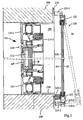
- FIG. 1 shows a horizontal section through the window system 100 according to the invention.
- the window system 100 comprises a window arrangement 110 and a protective glass arrangement 120.
- the window arrangement 110 is installed in an opening of a wall 200 in order to completely close this opening. With the degree The opening is also an otherwise limited by the wall 200 interior IR, for example, in a building completed.
- the window assembly 110 includes a window glass 112 and a window retainer 114 in the form of a window frame for holding the window glass 112 in the opening.
- the window assembly 110 is formed as a casement window, in which the window pane 112 is embedded in a casement 114-2, which in turn pivotally engages in a frame 200 connected to the wall frame 114-1.
- the window pane 112 is constructed as a laminated glass pane from a multiplicity of individual glass panes glued together and has an outer side AF facing away from the inner space IR and an inner side IF facing the inner space IR.
- the already mentioned protective glass arrangement 120 is arranged between the window arrangement 110 and the interior IR in such a way that it at least substantially covers the opening.
- the protective glass arrangement 120 serves, in the event of an explosion-induced fragmentation of the window arrangement, for example, to prevent the splinters or frame parts from flying in into the interior IR.
- It comprises a protective glass pane 126, typically also a laminated glass pane, which is preferably embedded in a protective glass window frame 122.
- the protective glass arrangement 120 further comprises a protective glass holding device 124.
- This holding device 124 consists of various elements described below, which selectively connect the protective glass pane or the protective glass window frame directly or indirectly to the wall 200. An indirect connection would be indicated if the elements of the holding device 124 were directly connected only to a frame 210, which in turn is directly connected to the wall 200.
- the protective glass holding device 124 is designed such that it has a lateral displacement (not shown in FIG. 1) or a pivoting, that is to say a turning away, tilting away or folding away the protective glass pane 126, optionally embedded in the protective glass window frame 122, in particular in a normal state, that is, without loading by an explosion-induced pressure wave allows.
- the described configuration of the protective glass holder 124 allows easy access to the inside IF of the window glass 112 and the entire window assembly 110, for example for cleaning purposes under normal circumstances.
- the entire protective glass arrangement 120 and its anchoring via the protective glass holding device 124 in the wall 200 or its reveal must be designed to be stable enough to withstand an explosion-induced pressure wave at least when the pressure wave has previously been significantly weakened by destruction of the window assembly 110 .
- the protective glass holding device 124 for this purpose comprises at least two bands 124-1 or two hinges for pivotally supporting the protective glass pane 126, optionally together with the protective glass window frame 122, and a locking device 124-2.
- the locking device is preferably mounted on a side of the protective glass window frame opposite the belts 124-1 and serves to releasably lock the protective glass pane 126, optionally together with the protective glass window frame 122 relative to the wall 200.
- FIG Wall or the frame 210 connected first stop 124-2, to which a spring element 124-4 is attached.
- the spring element 124-4 pulls the protective glass pane 126 or its frame 122 over a dome 124-3 secured to the pane or the frame with a bias against the first stop 124-2.
- the spring element 124-4 may, for example, be in the form of a rubber ring - or a closed, prestressed wire rope -, in particular as an O-ring. Under normal circumstances, the rubber ring can simply be manually pushed over the dome 124-3, whereupon the protective glass pane 126 can be moved away from the opening and the inside of the window assembly 110 is freely accessible.
- the spring element 124-4 offers the advantage that it is made yielding, and therefore a movement of the window pane 126 in the direction of the pressure wave, that is in the direction of the interior IR, permits, as indicated in Figure 1 by the dashed position of the window pane 126 and the window frame 122.
- the pressure wave is given conditionally, which advantageously has only a weakened load on the components involved, in particular the protective glass holding device result.
- the spring element 124-4 can also be designed as a gas pressure damper or indeed as a spring. It is advantageous if the movement of the protective glass pane 126, if appropriate together with the protective glass window frame 122, is limited to a predetermined path length in the event of an explosion-induced pressure effect in the interior IR by a suitable limiting device.
- a pair of scissors or a wire rope loop (not shown in FIG. 1) can serve as the limiting device, which in contrast to the spring element 124-4 is not yielding.
- the straps 124-1 may also be resiliently connected to the wall 200 such that, in the event of a compressive load on the protective glass assembly 120, the straps 124-1 may increase their distance from the wall 200 against the effect of increasing force , In this way - at approximately the same spring stiffness in the region of the closing device on the one hand and the bands 124-1 on the other hand - an approximately parallel displacement of the protective glass pane to the window assembly 110 can be achieved. This also creates the opportunity to achieve larger pressure equalization cross sections between the wall and the protective glass pane.
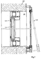
- FIG. 2 shows a vertical section of the same window system 100, of which FIG. 1 shows a horizontal section.
- Figure 2 shows a first variant of the protective glass assembly 120, which is characterized in that it the opening not in their entire cross-sectional area, in particular not in their entire height, covering or even overlapping.
- FIG. 3 shows the same window system 100 as FIG. 2, likewise in a vertical section, but this time with the casement window not in a closed position but in a tilted position.
- the meandered solid arrow in FIG. 3 symbolizes a ventilation duct from the outside of the window arrangement 110 into the interior IR.
- FIG. 4 shows a vertical section through the window system according to FIG. 1, but this time with a second variant of the protective glass arrangement 120.
- This second variant differs from the first variant shown in FIG. 2 in that it has a larger area and not only covers the opening. but even overlapping from their surface.
- This larger dimension of the protective glass arrangement provides improved protection against splinters flying around in the interior IR in the event of an explosion.
- the protective glass holding device 124 for connecting the protective glass pane 126 or its frame 122 to the wall 200 is not shown; rather, this holding device lies outside the plane of the drawing.
- FIGS. 2 to 4 show that all variants of the protective glass arrangement preferably provide an air gap between the wall 200 and the protective glass arrangement 120.
- the protective glass holding device 124 should not be formed circumferentially around the protective glass 126 or its protective glass window frame, but only in the form of punctual connections such as in the form of the band 124-1 or the stop 124-2.
- the air gap allows, at least when the casement window is open, an exchange of air between the interior IR and the outside of the wall or the window arrangement 110.
- Figure 5 shows essentially the horizontal section through the window system according to the invention according to Figure 1 with the only difference that the window assembly 110 now not as a casement window, but as a fixed field, that is not as is designed to open window.
- the window glass 112 is made of laminated glass.
- FIG. 6 again shows the horizontal section through the window system 100 according to the invention known from FIG. 1 with the only difference that the window pane 112 of the window arrangement 110 is no longer designed as a laminated glass pane but as a normal Thermopen pane.
- FIG. 7 again shows the horizontal section through the window system 100 according to the invention known from FIG. 1, with the only difference that the window arrangement 110 is designed here as a fixed field with a window pane 112 as normal Thermopen glazing.
Landscapes
- Engineering & Computer Science (AREA)
- Civil Engineering (AREA)
- Structural Engineering (AREA)
- Securing Of Glass Panes Or The Like (AREA)
- Wing Frames And Configurations (AREA)
Applications Claiming Priority (1)
| Application Number | Priority Date | Filing Date | Title |
|---|---|---|---|
| DE102004057470A DE102004057470A1 (de) | 2004-11-29 | 2004-11-29 | Explosionshemmendes Fenstersystem |
Publications (3)
| Publication Number | Publication Date |
|---|---|
| EP1662086A2 true EP1662086A2 (fr) | 2006-05-31 |
| EP1662086A3 EP1662086A3 (fr) | 2007-01-10 |
| EP1662086B1 EP1662086B1 (fr) | 2008-03-12 |
Family
ID=35841684
Family Applications (1)
| Application Number | Title | Priority Date | Filing Date |
|---|---|---|---|
| EP05024957A Ceased EP1662086B1 (fr) | 2004-11-29 | 2005-11-15 | Système de fenêtre à l'épreuve de l'effet d'explosion |
Country Status (3)
| Country | Link |
|---|---|
| US (1) | US20060112641A1 (fr) |
| EP (1) | EP1662086B1 (fr) |
| DE (2) | DE102004057470A1 (fr) |
Cited By (2)
| Publication number | Priority date | Publication date | Assignee | Title |
|---|---|---|---|---|
| GB2440994A (en) * | 2005-11-29 | 2008-02-20 | John Blay | Security glazing panel |
| EP2149661A1 (fr) * | 2008-07-25 | 2010-02-03 | Sälzer Sicherheitstechnik GmbH | Fermeture de bâtiment résistante aux explosions et à l'effraction |
Families Citing this family (8)
| Publication number | Priority date | Publication date | Assignee | Title |
|---|---|---|---|---|
| US7975432B2 (en) * | 2006-09-05 | 2011-07-12 | Deceuninck North America, Llc | Casement window assembly with windload and impact resistance |
| FR2932214B1 (fr) * | 2008-06-10 | 2013-03-29 | Nexter Systems | Dispositif de protection d'un ouvrant de vehicule |
| GB2480466A (en) * | 2010-05-19 | 2011-11-23 | Adam Wladyslaw Wiktor Dudley | Secondary glazing sash stop |
| AU2014357743B2 (en) * | 2013-12-03 | 2018-08-23 | Aja Enterprises Pte Ltd | A panel assembly |
| US12012801B2 (en) * | 2019-09-30 | 2024-06-18 | United States Of America As Represented By The Secretary Of The Army | Hardened operable window systems and methods |
| RU203439U1 (ru) * | 2020-11-09 | 2021-04-05 | Александр Федорович Миронов | Откидная легкосбрасываемая конструкция |
| GB2596374B (en) * | 2021-01-21 | 2022-08-03 | Cenegex Ltd | Inspection window |
| CN117684852A (zh) * | 2023-12-05 | 2024-03-12 | 安徽钟南消防科技有限公司 | 塑钢超低能耗耐火窗 |
Citations (3)
| Publication number | Priority date | Publication date | Assignee | Title |
|---|---|---|---|---|
| DE8417098U1 (de) | 1984-06-05 | 1986-05-28 | Sälzer, Heinrich, 3550 Marburg | Sprengwirkungshemmende Verglasung |
| US5915449A (en) | 1998-05-18 | 1999-06-29 | Schwartz; Craig | Bomb blast drapery |
| EP1035295A2 (fr) | 1999-03-11 | 2000-09-13 | Arpal Aluminium Ltd | Fenêtres résistants |
Family Cites Families (10)
| Publication number | Priority date | Publication date | Assignee | Title |
|---|---|---|---|---|
| DE3420883C2 (de) * | 1983-07-28 | 1985-07-18 | Heinrich 3550 Marburg Sälzer | Sprengwirkungshemmende Verglasung |
| CH667127A5 (de) * | 1983-07-28 | 1988-09-15 | Heinrich Saelzer | Sprengwirkungshemmende verglasung. |
| DE3432021A1 (de) * | 1984-08-31 | 1986-03-13 | Heinrich 3550 Marburg Sälzer | Sicherheitsfenster oder -tuer |
| DE19711208A1 (de) * | 1997-03-18 | 1998-09-24 | Rudolf Hajek | Druckentlastungsklappe |
| IL123980A (en) * | 1998-04-07 | 2000-10-31 | Arpal Aluminum Ltd | Blast resistant window framework and elements thereof |
| US5934020A (en) * | 1998-07-29 | 1999-08-10 | Mccracken; Robert | Window lock and guard |
| US6363669B1 (en) * | 1999-10-22 | 2002-04-02 | Robert E. Hoffman | Penetration resistant storm window |
| US6333085B1 (en) * | 1999-11-08 | 2001-12-25 | Arpal Aluminum, Ltd. | Resistant window systems |
| EP1640550B1 (fr) * | 2003-09-22 | 2007-11-21 | Sälzer Sicherheitstechnik GmbH | Fenêtre résistant aux explosions |
| DE202004006268U1 (de) * | 2004-03-09 | 2004-08-05 | Sälzer Sicherheitstechnik GmbH | Sprengwirkungshemmendes Fenster |
-
2004
- 2004-11-29 DE DE102004057470A patent/DE102004057470A1/de not_active Withdrawn
-
2005
- 2005-11-15 DE DE502005003183T patent/DE502005003183D1/de not_active Expired - Lifetime
- 2005-11-15 EP EP05024957A patent/EP1662086B1/fr not_active Ceased
- 2005-11-29 US US11/288,543 patent/US20060112641A1/en not_active Abandoned
Patent Citations (3)
| Publication number | Priority date | Publication date | Assignee | Title |
|---|---|---|---|---|
| DE8417098U1 (de) | 1984-06-05 | 1986-05-28 | Sälzer, Heinrich, 3550 Marburg | Sprengwirkungshemmende Verglasung |
| US5915449A (en) | 1998-05-18 | 1999-06-29 | Schwartz; Craig | Bomb blast drapery |
| EP1035295A2 (fr) | 1999-03-11 | 2000-09-13 | Arpal Aluminium Ltd | Fenêtres résistants |
Cited By (2)
| Publication number | Priority date | Publication date | Assignee | Title |
|---|---|---|---|---|
| GB2440994A (en) * | 2005-11-29 | 2008-02-20 | John Blay | Security glazing panel |
| EP2149661A1 (fr) * | 2008-07-25 | 2010-02-03 | Sälzer Sicherheitstechnik GmbH | Fermeture de bâtiment résistante aux explosions et à l'effraction |
Also Published As
| Publication number | Publication date |
|---|---|
| US20060112641A1 (en) | 2006-06-01 |
| EP1662086B1 (fr) | 2008-03-12 |
| EP1662086A3 (fr) | 2007-01-10 |
| DE502005003183D1 (de) | 2008-04-24 |
| DE102004057470A1 (de) | 2006-06-01 |
Similar Documents
| Publication | Publication Date | Title |
|---|---|---|
| EP1516996B1 (fr) | Fenêtre résistant aux explosions | |
| DE3432021C2 (fr) | ||
| EP1662086B1 (fr) | Système de fenêtre à l'épreuve de l'effet d'explosion | |
| EP1645714B1 (fr) | Liaison entre cadre et panneau | |
| EP1944432B1 (fr) | Composant inhibiteur d'explosion | |
| WO1992001854A1 (fr) | Porte de securite a fermeture hermetique s'ouvrant dans les deux sens | |
| EP2058459B1 (fr) | Fermeture de bâtiment dotée d'un élément de déverrouillage de panique dans une construction résistante aux implosions | |
| EP2149661B1 (fr) | Fermeture de bâtiment résistante aux explosions et à l'effraction | |
| DE10164212B4 (de) | Sprengwirkungshemmendes Fenster | |
| DE202005018493U1 (de) | Explosionshemmendes Fenstersystem | |
| EP0978617B1 (fr) | Dispositif d'ouverture de fenêtre | |
| CH715780A2 (de) | Insektenschutzvorrichtung für eine mittels Fenster oder Tür verschlissbare Öffnung. | |
| DE102005037774B3 (de) | Rollladen zur außenseitigen Montage über einem ausschwenkbaren Fenster | |
| EP0828913B1 (fr) | Systeme de protection contre les cambriolages | |
| EP4446556B1 (fr) | Dispositif d'ombrage d'une ouverture de bâtiment et rail de guidage latéral associé | |
| EP2372047B1 (fr) | Structure de construction à l'épreuve des explosions et des balles, ainsi que procédé de fabrication de celle-ci | |
| DE3014557A1 (de) | Abdeckvortrichtung fuer eine druckentlastungsoeffnung in einem der aufstellung von mittelspannungs- oder hochspannungsschaltanlagen dienenden gebaeude oder raum | |
| DE102011113820A1 (de) | Türanordnung | |
| DE20310069U1 (de) | Sprengwirkungshemmende Verglasung | |
| EP1790815B1 (fr) | Système de fenêtre et/ou facade | |
| AT505570B1 (de) | Zarge mit falz für zumindest einen flügel | |
| EP0690196B1 (fr) | Fenêtre à l'épreuve des balles | |
| EP4534792A1 (fr) | Porte avec segments de porte mobiles | |
| DE202004006268U1 (de) | Sprengwirkungshemmendes Fenster | |
| DE10329603A1 (de) | Sprengwirkungshemmende Verglasung |
Legal Events
| Date | Code | Title | Description |
|---|---|---|---|
| PUAI | Public reference made under article 153(3) epc to a published international application that has entered the european phase |
Free format text: ORIGINAL CODE: 0009012 |
|
| AK | Designated contracting states |
Kind code of ref document: A2 Designated state(s): AT BE BG CH CY CZ DE DK EE ES FI FR GB GR HU IE IS IT LI LT LU LV MC NL PL PT RO SE SI SK TR |
|
| AX | Request for extension of the european patent |
Extension state: AL BA HR MK YU |
|
| PUAL | Search report despatched |
Free format text: ORIGINAL CODE: 0009013 |
|
| AK | Designated contracting states |
Kind code of ref document: A3 Designated state(s): AT BE BG CH CY CZ DE DK EE ES FI FR GB GR HU IE IS IT LI LT LU LV MC NL PL PT RO SE SI SK TR |
|
| AX | Request for extension of the european patent |
Extension state: AL BA HR MK YU |
|
| 17P | Request for examination filed |
Effective date: 20070131 |
|
| AKX | Designation fees paid |
Designated state(s): DE GB |
|
| GRAP | Despatch of communication of intention to grant a patent |
Free format text: ORIGINAL CODE: EPIDOSNIGR1 |
|
| GRAS | Grant fee paid |
Free format text: ORIGINAL CODE: EPIDOSNIGR3 |
|
| GRAA | (expected) grant |
Free format text: ORIGINAL CODE: 0009210 |
|
| AK | Designated contracting states |
Kind code of ref document: B1 Designated state(s): DE GB |
|
| REG | Reference to a national code |
Ref country code: GB Ref legal event code: FG4D Free format text: NOT ENGLISH |
|
| REF | Corresponds to: |
Ref document number: 502005003183 Country of ref document: DE Date of ref document: 20080424 Kind code of ref document: P |
|
| GBT | Gb: translation of ep patent filed (gb section 77(6)(a)/1977) |
Effective date: 20080429 |
|
| PLBE | No opposition filed within time limit |
Free format text: ORIGINAL CODE: 0009261 |
|
| STAA | Information on the status of an ep patent application or granted ep patent |
Free format text: STATUS: NO OPPOSITION FILED WITHIN TIME LIMIT |
|
| 26N | No opposition filed |
Effective date: 20081215 |
|
| REG | Reference to a national code |
Ref country code: DE Ref legal event code: R082 Ref document number: 502005003183 Country of ref document: DE Representative=s name: BAUER WAGNER PRIESMEYER, PATENT- UND RECHTSANW, DE Effective date: 20131205 Ref country code: DE Ref legal event code: R081 Ref document number: 502005003183 Country of ref document: DE Owner name: SAELZER GMBH, DE Free format text: FORMER OWNER: SAELZER SICHERHEITSTECHNIK GMBH, 35037 MARBURG, DE Effective date: 20131205 Ref country code: DE Ref legal event code: R082 Ref document number: 502005003183 Country of ref document: DE Representative=s name: PATENT- & RECHTSANWAELTE BAUER WAGNER PRIESMEY, DE Effective date: 20131205 |
|
| PGFP | Annual fee paid to national office [announced via postgrant information from national office to epo] |
Ref country code: GB Payment date: 20211123 Year of fee payment: 17 Ref country code: DE Payment date: 20211130 Year of fee payment: 17 |
|
| REG | Reference to a national code |
Ref country code: DE Ref legal event code: R082 Ref document number: 502005003183 Country of ref document: DE Representative=s name: BAUER WAGNER PELLENGAHR SROKA PATENT- & RECHTS, DE |
|
| REG | Reference to a national code |
Ref country code: DE Ref legal event code: R119 Ref document number: 502005003183 Country of ref document: DE |
|
| GBPC | Gb: european patent ceased through non-payment of renewal fee |
Effective date: 20221115 |
|
| PG25 | Lapsed in a contracting state [announced via postgrant information from national office to epo] |
Ref country code: GB Free format text: LAPSE BECAUSE OF NON-PAYMENT OF DUE FEES Effective date: 20221115 Ref country code: DE Free format text: LAPSE BECAUSE OF NON-PAYMENT OF DUE FEES Effective date: 20230601 |