EP1661822A1 - Verpackung und Ausgabevorrichtung für ein Produkt - Google Patents
Verpackung und Ausgabevorrichtung für ein Produkt Download PDFInfo
- Publication number
- EP1661822A1 EP1661822A1 EP05292168A EP05292168A EP1661822A1 EP 1661822 A1 EP1661822 A1 EP 1661822A1 EP 05292168 A EP05292168 A EP 05292168A EP 05292168 A EP05292168 A EP 05292168A EP 1661822 A1 EP1661822 A1 EP 1661822A1
- Authority
- EP
- European Patent Office
- Prior art keywords
- diffuser
- dispensing
- trigger
- container
- distribution
- Prior art date
- Legal status (The legal status is an assumption and is not a legal conclusion. Google has not performed a legal analysis and makes no representation as to the accuracy of the status listed.)
- Granted
Links
Images

Classifications
-
- B—PERFORMING OPERATIONS; TRANSPORTING
- B65—CONVEYING; PACKING; STORING; HANDLING THIN OR FILAMENTARY MATERIAL
- B65D—CONTAINERS FOR STORAGE OR TRANSPORT OF ARTICLES OR MATERIALS, e.g. BAGS, BARRELS, BOTTLES, BOXES, CANS, CARTONS, CRATES, DRUMS, JARS, TANKS, HOPPERS, FORWARDING CONTAINERS; ACCESSORIES, CLOSURES, OR FITTINGS THEREFOR; PACKAGING ELEMENTS; PACKAGES
- B65D83/00—Containers or packages with special means for dispensing contents
- B65D83/14—Containers for dispensing liquid or semi-liquid contents by internal gaseous pressure, i.e. aerosol containers comprising propellant
- B65D83/16—Actuating means
- B65D83/22—Actuating means with means to disable actuation
- B65D83/224—Tamper-indicating means obstructing initial actuation
- B65D83/226—Tamper-indicating means obstructing initial actuation preventing initial depression of the actuator
-
- B—PERFORMING OPERATIONS; TRANSPORTING
- B65—CONVEYING; PACKING; STORING; HANDLING THIN OR FILAMENTARY MATERIAL
- B65D—CONTAINERS FOR STORAGE OR TRANSPORT OF ARTICLES OR MATERIALS, e.g. BAGS, BARRELS, BOTTLES, BOXES, CANS, CARTONS, CRATES, DRUMS, JARS, TANKS, HOPPERS, FORWARDING CONTAINERS; ACCESSORIES, CLOSURES, OR FITTINGS THEREFOR; PACKAGING ELEMENTS; PACKAGES
- B65D83/00—Containers or packages with special means for dispensing contents
- B65D83/14—Containers for dispensing liquid or semi-liquid contents by internal gaseous pressure, i.e. aerosol containers comprising propellant
- B65D83/16—Actuating means
- B65D83/18—Hand lever actuators
-
- B—PERFORMING OPERATIONS; TRANSPORTING
- B65—CONVEYING; PACKING; STORING; HANDLING THIN OR FILAMENTARY MATERIAL
- B65D—CONTAINERS FOR STORAGE OR TRANSPORT OF ARTICLES OR MATERIALS, e.g. BAGS, BARRELS, BOTTLES, BOXES, CANS, CARTONS, CRATES, DRUMS, JARS, TANKS, HOPPERS, FORWARDING CONTAINERS; ACCESSORIES, CLOSURES, OR FITTINGS THEREFOR; PACKAGING ELEMENTS; PACKAGES
- B65D83/00—Containers or packages with special means for dispensing contents
- B65D83/14—Containers for dispensing liquid or semi-liquid contents by internal gaseous pressure, i.e. aerosol containers comprising propellant
- B65D83/16—Actuating means
- B65D83/22—Actuating means with means to disable actuation
- B65D83/224—Tamper-indicating means obstructing initial actuation
- B65D83/228—Tamper-indicating means obstructing initial actuation consisting of a rupturable connection between actuator element and actuator cap or skirt, e.g. tear strips or bridges
Definitions
- the present invention relates to a device for packaging and dispensing a product, especially a cosmetic product.
- a product may be distributed in particular in the form of a cream, a gel, a mousse or a spray.
- Cosmetic product means a product as defined in Council Directive 93/35 / EEC of 14 June 1993, amending for the sixth time Directive 76/768 / EEC.
- a packaging and dispensing device comprises a container containing the product to be dispensed equipped with a dispensing element.
- a dispensing element may be a pump or a valve which is surmounted by a diffuser.
- the diffuser allows the user to route the product exiting the container to a dispensing orifice. It can further control the actuation of the dispensing member to eject a dose of product out of the container.
- a diffuser of substantially cylindrical shape comprising a spray orifice, such as that described in US Pat. No. 4,401,240, the diffuser being freely mounted on an actuating rod of the actuating element so as to be able to move it to activate it.
- a diffuser is relatively easy to handle so that it can easily be placed on the actuating rod on the assembly lines of the devices.
- the rod can be substantially depressed and product can escape from the container.
- the document EP1024094 describes a dispensing head which comprises a body intended to be fixed on a container and a push-button made from a single piece with the body, the body and the push-button being connected by material bridges. which are broken before mounting the head on the container or during assembly. The bridges of material are thus broken before a first use of the assembly. Such a device can therefore be actuated accidentally before a first use.
- the diffuser may be connected, prior to a first actuation of the distribution element, to the mounting member by at least one bridge of material in a position such that the diffuser is not in fluid communication with the element of distribution, the material bridge being fracturable during the first actuation so as to allow the fluidic engagement of the dispensing element with the diffuser.
- the diffuser is not in fluid communication with the distribution element means that there is no sealed connection between the two parts and that the product can not be transferred from the distribution element to the diffuser without there is no escape.
- Such a position of the diffuser relative to the dispensing element makes it possible to limit the risks of actuation of the dispensing element during the assembly of the dispensing head on the container on the assembly lines and therefore the risks of product leak.
- the trigger makes it possible to limit the efforts necessary to actuate the pump and to improve the comfort of use and the gestures of the application. It is therefore possible to spray relatively viscous products such as milk or still the oils, which require the use of precompression pumps to be able to form a spray of good quality, consisting in particular of fine particles.
- the trigger also allows the user to easily fracture the material bridge during the first actuation of the dispensing element by limiting the efforts required to fracture. Relatively solid material bridges can thus be used so as to limit the risks that they are accidentally fractured, while being easily broken during the first actuation of the dispensing element through the lever effect of the trigger.
- a portion of the diffuser intended to be in fluid communication with a portion of the distribution element may be located, before the first actuation of the distribution element, at a non-zero distance, measured along the longitudinal axis of the element distribution, of said portion of the distribution element.
- the diffuser is at an axial position different from its axial position before a first actuation.
- the diffuser may comprise a sleeve for sealingly engaging an actuating rod of the dispensing element, a lower edge of the sleeve being located above an upper edge of the actuating rod before a first actuation of the dispensing element.
- the mounting member may be connected to the diffuser by several material bridges, including four material bridges.
- the diffuser may comprise a cylindrical skirt provided with a lower edge, the bridge (s) material being formed (s) on the lower edge of the cylindrical skirt.
- the mounting member and the diffuser can be obtained from one piece molding. This limits the number of parts to be made and therefore the manufacturing cost of the device.
- the diffuser may be configured to depress the dispensing member along the longitudinal axis of the dispensing member to actuate it.
- the dispensing element may be a pump. Alternatively, the dispensing element could be a valve.
- the mounting member may be connected to the diffuser by a flexible band which allows the movement of the diffuser relative to the mounting member.
- the diffuser thus remains integral with the mounting member, even after breaking the material bridges during the first actuation.
- the mounting member may comprise a hoop adapted to be fixed on a neck of the container or on a skirt for fixing the dispensing element on the container.
- the hoop may be configured to snap onto the neck of the container or the skirt for fixing the dispensing element on the container or, alternatively, may include a thread for screwing the head on the neck of the container.
- the diffuser may include a cannula that opens through the dispensing orifice.
- the cannula may be elongated along an axis distinct from the longitudinal axis of the dispensing element, in particular along a substantially perpendicular axis. It is thus possible to distribute the product in a relatively precise manner.
- the trigger can be obtained from molding from a single piece with the diffuser and the mounting member.
- the dispensing head can thus be obtained from a single piece, and therefore at a lower cost.
- the trigger can be connected to the mounting member by a flexible tab.
- the trigger can be articulated on the mounting member, in particular by a first end of the trigger.
- the first end of the trigger may comprise two lateral openings intended to define an axis of articulation, in particular an axis substantially perpendicular to the axis longitudinal of the trigger.
- the two openings may be configured to receive two protuberances provided on the mounting member so as to allow a tilting movement of the trigger relative to the mounting member about the hinge axis.
- the trigger may include a second end for forming a bearing surface for controlling actuation of the dispensing member.
- the trigger may be configured to depress the diffuser to actuate the dispensing member.
- the trigger may comprise at least one lug adapted to bear on an upper wall of the diffuser.
- the lug may be configured to be housed in a corresponding recess provided on the upper wall of the diffuser. This ensures that the diffuser is correctly positioned during the actuation of the dispensing element.
- the trigger may include a window through which the cannula passes.
- the device may comprise a locking member adapted to limit the movement of the trigger so as to prevent actuation of the dispensing element.
- the locking member may for example comprise a rod adapted to pass through a slot provided in the trigger, the rod may comprise a shoulder on which a portion of the trigger is adapted to bear.
- the rod may in particular be integral with the mounting member and be obtained from molding from one piece with the other components of the dispensing head. Of course, any other locking member can be used.
- the container may contain a cosmetic product.
- the device is particularly useful for packaging and dispensing a cosmetic product, especially in the form of a cream, a mousse, a gel or a spray.
- the device 1 comprises a container 10, made for example of thermoplastic material. It is obvious that any other material can be used to make the container and in particular tinplate or aluminum.
- the container 10 comprises a body 11, for example of generally spherical shape which has an open neck 12 in which is mounted a pump 20 of longitudinal axis X, via a fixing skirt 23 which is fixed on the wall
- the container may alternatively have any other shape, in particular a cylindrical shape.
- the pump 20 which is not shown in detail in the figures, is a standard pump, preferably with precompression.
- the pump comprises a piston whose movement inside the pump body, in one direction, causes the product to exit under pressure, and in the other direction, causes the product to be sucked into the pump body.
- the piston is constrained in its position corresponding to the maximum volume of the chamber of pumping by means of a spring.
- the pump comprises an actuating rod 21 which can be displaced along its longitudinal axis by exerting a pressure on it to actuate the pump.
- the container 10 is surmounted by a dispensing head which can be fixed to the pump 20 by means of a mounting member 30 in the form of a hoop.
- the hoop 30 is fixed, for example by snapping, on the pump.
- the hoop 30 comprises for example an annular bead 36 configured to be housed in a rod 22 provided on the fixing skirt 23 of the pump.
- the hoop 30 could comprise a bead 36 on its lower edge intended to be housed under the lower edge of the fixing skirt 23 of the pump.
- the hoop 30 has two extra thicknesses 31, diametrically opposed, each forming a flange 32 on the outer surface of the hoop.
- the two flanges 32 thus formed, visible in Figures 1 and 2, serve as a bearing surface for the tool used to snap the band on the pump.
- the dispensing head further comprises a diffuser 40 configured to drive the actuating rod 21 of the pump longitudinally in order to actuate it, the diffuser further delimiting a channel 47 provided for conveying the product from the container from the stem. actuating to a spray orifice 45.
- the diffuser 40 includes a sleeve 41 for engaging directly on the actuating rod.
- the sleeve 41 defines a first portion of the routing channel 47 of the product.
- the delivery channel 47 is extended by a second portion, transverse to the first, which is delimited by a cannula 44.
- the cannula 44 is of elongate shape along an axis substantially perpendicular to the longitudinal axis X of the pump, and extends from the sleeve 41 to an end opening through the spray orifice 45.
- the end of the cannula 44 comprises a nozzle holder 48, provided with a pad also called “centerpost”, on which can be fixed an effect nozzle Vortex 49, conventional, as can be seen in the figures, the nozzle defining the spray orifice 45.
- the presence of the nozzle makes it possible to spray the product in the form of a spray of good quality.
- the diffuser 40 also comprises a cylindrical skirt 42 which surrounds the sleeve 41 and which is closed in its upper part by a transverse wall 43.
- the transverse wall 43 is provided with two straight and parallel recesses 46, visible in FIGS. 2 and 4, whose function will be explained later in the description.
- the diffuser 40 Since the diffuser 40 is intended to drive the actuating rod, it must be able to move relative to the hoop 30, which itself is fixed on the container. It is preferably provided that the cylindrical skirt 42 of the diffuser has a diameter substantially smaller than the diameter of the hoop 30 so as to form an annular space 37 between the two parts which allows the diffuser to sink inside the hoop.
- the diffuser 40 is connected, before a first actuation of the dispensing element, to the band 30 by at least one material bridge 50 which connects the lower edge 42a of the skirt 42, to the band 30.
- four material bridges 50 are provided between the two parts.
- the material bridges 50 extend transversely to the X axis in the annular space 37.
- the material bridges 50 are sufficiently strong to hold the diffuser on the hoop when assembling the head on the container but sufficiently weak to break during the first depression of the diffuser 40 actuating the pump 20.
- the hoop 30 and the diffuser 40 are thus obtained molding from a single piece.
- the diffuser 40 When the head is assembled on the container, the diffuser 40 is in a position such that it is not in fluid communication with the actuating rod 21 of the dispensing member.
- the sleeve 43 of diffuser is above the actuating rod 21, and is flush with the upper end of the actuating rod 21 as can be seen in Figure 8, without being fitted on it.
- the material bridges 50 thus make it possible to maintain the diffuser at the desired distance from the pump before a first actuation. They also constitute tamper pins that ensure the user who buys a device that it has never been used.
- the diffuser 40 is further connected to the band 30 by a flexible band 35 which allows the movement of the diffuser relative to the mounting member.
- a flexible band 35 keeps the two parts integral with each other after the rupture of the material bridges 50 so as to limit the risk that the diffuser is lost.
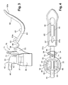
- a trigger 60 is provided to control the actuation of the pump by pressing the diffuser 40, which itself drives the actuating rod 21.
- the trigger 60 is formed by a angled lever arm having two portions 61 and 62 forming an angle therebetween, the trigger 50 having a longitudinal axis extending in a plane parallel to the axis X.
- the first portion 61 has a first end 61a articulated on the hoop 30 so as to allow the trigger 60 to pivot about an axis perpendicular to the axis X.
- the first end 61a is articulated on an intermediate element 33, integral with the hoop 30, which allows move the hinge joint to allow the trigger to pivot.
- the first end 61a of the trigger has two lateral openings 63 intended to define an axis of articulation, in particular an axis substantially perpendicular to the longitudinal axis of the trigger.
- the two openings 63 are configured to receive two protuberances 34 provided on the intermediate piece 33 so as to allow a tilting movement of the trigger relative to the mounting member about the hinge axis.
- the first portion 61 extends, from the articulation, in the direction of the diffuser above it, to the bent portion located substantially above the transverse wall. of the broadcaster.
- the second portion 62 of the trigger returns to the other side of the diffuser.
- the second portion 62 of the trigger extends from the bent portion away from the diffuser and towards the container 10 to a second end 62a of the trigger.
- the second end 62a forms a surface on which the user can press to rotate the trigger.
- the trigger 60 is relatively long so as to optimize the leverage effect and therefore the comfort in use.
- the bearing surface 62a on which an actuating force is exerted is located on one side of a plane passing through the X axis while the hinge is situated on the other side of the plane so as to facilitate the actuation of the pump.
- two lugs 65 are provided under the portion 61 of the trigger to come to press the transverse wall 43 of the diffuser and allow the actuation of the pump.
- the two lugs are provided to be housed in the two recesses 46 provided on the transverse wall 43 of the diffuser.
- the second portion 62 of the trigger is further provided with a window 64 which can be traversed by the cannula 44. The trigger can thus be extended below the cannula.
- the trigger 60 has a cross section U, that is to say it has a groove along its length, the groove being defined by two flanges 60a provided on each edge of the trigger .
- the trigger 60 may be made separately from the band 30, or as in the example illustrated in the figures, be obtained molding from a single piece with the diffuser and the mounting member.
- the trigger is indeed connected to the intermediate element 33 of the band 30 by a flexible tab 66.
- the flexible tab 66 is not provided. It is preferable to use a more rigid material than used to achieve the rest of the dispensing head so as to obtain a relatively strong lever arm to be easily operated.
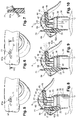
- a locking member 70 is provided to limit the movement of the trigger so as to prevent actuation of the dispensing member.
- the locking member comprises a rod 70 which extends parallel to the X axis from the intermediate element 33 to a free end 71 thinner than the rest of the rod 70, a shoulder 72 being provided between the thinner portion and the remainder of the rod 70 to serve as a stop for a portion of the trigger.
- the free end 71 of the rod 70 is configured to pass through a slot 67 provided in the trigger as seen in FIG.
- the slot 67 extends longitudinally in the first portion of the trigger over a length sufficient to allow the end 71 of the rod 70 not to prevent the trigger from moving when the trigger is actuated.
- the slot 67 is widened on a small portion 67a of its length. This portion 67a is provided to receive the free end 71 of the rod 70 when it is desired to lock the device.
- the trigger In this position illustrated in Figures 6 and 7, the trigger is in abutment against the shoulder 72 of the rod and also against the edges of the trigger 60 defining the portion 67a of the slot.
- the portion 62a of the trigger the latter being in abutment against the rod 71, it can not be moved enough for the pins 65 to depress the diffuser 40 and that the actuating rod is pressed.
- any other locking member is used.
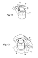
- a flap 73 hinged to the trigger the flap having a free end 73a intended to bear against the diffuser 40 to lock the trigger, as illustrated in FIG. 12.
- the pump 20 is first fixed in the neck of the container, for example by snapping its fixing skirt 23 onto the external wall of the neck 12.
- the dispensing head is produced by molding the dispensing head from a single piece, the diffuser 40 being secured to the band 30 by the material bridges 50.
- the presence of the material bridges also makes it possible to hold the diffuser in the correct position relative to the hoop, and especially relative to the trigger, so that the cannula 44 is correctly positioned to cross the opening 64 in the trigger.
- the trigger is molded in the open position, as illustrated in Figures 2 to 4, the trigger being connected to the rest of the head by the flexible tab 66.
- the trigger 60 Before mounting the head on the container, the trigger 60 is folded over the diffuser 40 and the two protuberances 34 of the intermediate element 33 are inserted into the two openings 63 provided at one end of the trigger so as to form the articulation between the trigger and the hoop.
- the head can thus be fixed on the container in this configuration.
- the sleeve 41 is not in engagement with the actuating rod 21 so that the actuating rod is not likely to be depressed during the assembly of the head on the container.
- the user holds the container 10 and / or the hoop 30 in one hand and can actuate the trigger 60 by pressing, with one of the fingers of his hand, on the surface support 62a.
- the material bridges 50 will break under the effect of the pressure exerted by the trigger on the diffuser while the hoop 60 remains fixed on the container 20.
- the presence of the recesses 46 in the diffuser associated with the pins 65 of the trigger ensures that the diffuser, and in particular the cannula, is always correctly positioned relative to the trigger 60, in case, for example, the diffuser 40 has rotated relative to the ferrule 30 .
- the product When the diffuser 40 is depressed, the product can be sprayed as seen in FIG. 9.
- the diffuser 40 When the diffuser 40 is again at rest as illustrated in Figure 10, it is at an axial position different from its initial position before a first actuation.
- the diffuser 40 is substantially depressed in the band 30 and the sleeve 41 is fitted on the actuating rod 21.
- the lugs 65 are substantially driven into the recesses 46 so as to prevent the diffuser 40 from rotating. compared to the hoop 30 between two uses.
- Rod 70 is indeed sufficiently flexible so that its free end 71 can move relative to its base.
Landscapes
- Chemical & Material Sciences (AREA)
- Dispersion Chemistry (AREA)
- Engineering & Computer Science (AREA)
- Mechanical Engineering (AREA)
- Containers And Packaging Bodies Having A Special Means To Remove Contents (AREA)
- Closures For Containers (AREA)
- Vending Machines For Individual Products (AREA)
- Devices For Dispensing Beverages (AREA)
- Cosmetics (AREA)
- Coating Apparatus (AREA)
Applications Claiming Priority (1)
| Application Number | Priority Date | Filing Date | Title |
|---|---|---|---|
| FR0452792A FR2878511B1 (fr) | 2004-11-29 | 2004-11-29 | Dispositif de conditionnement et de distribution d'un produit |
Publications (2)
| Publication Number | Publication Date |
|---|---|
| EP1661822A1 true EP1661822A1 (de) | 2006-05-31 |
| EP1661822B1 EP1661822B1 (de) | 2008-10-01 |
Family
ID=34954294
Family Applications (1)
| Application Number | Title | Priority Date | Filing Date |
|---|---|---|---|
| EP05292168A Expired - Lifetime EP1661822B1 (de) | 2004-11-29 | 2005-10-14 | Verpackung und Ausgabevorrichtung für ein Produkt |
Country Status (6)
| Country | Link |
|---|---|
| EP (1) | EP1661822B1 (de) |
| AT (1) | ATE409662T1 (de) |
| BR (1) | BRPI0504732A (de) |
| DE (1) | DE602005010029D1 (de) |
| ES (1) | ES2314598T3 (de) |
| FR (1) | FR2878511B1 (de) |
Cited By (6)
| Publication number | Priority date | Publication date | Assignee | Title |
|---|---|---|---|---|
| US20070119870A1 (en) * | 2004-01-05 | 2007-05-31 | L'oreal | Lockable dispensing head |
| EP1862400A1 (de) * | 2006-06-02 | 2007-12-05 | Wella Aktiengesellschaft | Kappe mit einem Betätigungsschutz für einen Sprühbehälter |
| EP2060507A2 (de) | 2007-11-15 | 2009-05-20 | L'oreal | Verteilerkopf vom Typ Auslösung durch Triggern der Steuerelektrode |
| WO2011034869A1 (en) * | 2009-09-15 | 2011-03-24 | Meadwestvaco Calmar, Inc. | Trigger sprayer comprising a movable shroud having a pump actuating ramp and arm |
| WO2016156723A1 (fr) * | 2015-03-30 | 2016-10-06 | Ys Lab | Tête de pulvérisation universelle et sécuritaire pour spray |
| WO2021185981A1 (fr) * | 2020-03-18 | 2021-09-23 | Lindal France Sas | Tête de distribution du type à gâchette |
Families Citing this family (2)
| Publication number | Priority date | Publication date | Assignee | Title |
|---|---|---|---|---|
| FR2923811B1 (fr) | 2007-11-15 | 2009-12-04 | Oreal | Recipient equipe d'un dispositif de securite. |
| DE202009007139U1 (de) | 2009-02-27 | 2009-08-13 | Seaquist Perfect Dispensing Gmbh | Hebelsprühpumpe |
Citations (4)
| Publication number | Priority date | Publication date | Assignee | Title |
|---|---|---|---|---|
| GB1324408A (en) * | 1970-07-15 | 1973-07-25 | Green E H | Actuator overcap for aerosol dispensing packages |
| FR2225929A5 (de) * | 1973-04-13 | 1974-11-08 | Reboul Sa Sofra | |
| FR2257836A1 (en) * | 1974-01-10 | 1975-08-08 | Aerosol Inventions Dev | Aerosol container spray head - has hollow shaft passing with play through valeve-seating seal, and has longitudinal slots in wall |
| AU529646B2 (en) * | 1975-12-03 | 1983-06-16 | Aerosol Inventions And Development S.A. Aidsa | Actuator cap for aerosol |
-
2004
- 2004-11-29 FR FR0452792A patent/FR2878511B1/fr not_active Expired - Fee Related
-
2005
- 2005-10-14 AT AT05292168T patent/ATE409662T1/de not_active IP Right Cessation
- 2005-10-14 ES ES05292168T patent/ES2314598T3/es not_active Expired - Lifetime
- 2005-10-14 DE DE602005010029T patent/DE602005010029D1/de not_active Expired - Lifetime
- 2005-10-14 EP EP05292168A patent/EP1661822B1/de not_active Expired - Lifetime
- 2005-10-19 BR BRPI0504732-3A patent/BRPI0504732A/pt not_active IP Right Cessation
Patent Citations (4)
| Publication number | Priority date | Publication date | Assignee | Title |
|---|---|---|---|---|
| GB1324408A (en) * | 1970-07-15 | 1973-07-25 | Green E H | Actuator overcap for aerosol dispensing packages |
| FR2225929A5 (de) * | 1973-04-13 | 1974-11-08 | Reboul Sa Sofra | |
| FR2257836A1 (en) * | 1974-01-10 | 1975-08-08 | Aerosol Inventions Dev | Aerosol container spray head - has hollow shaft passing with play through valeve-seating seal, and has longitudinal slots in wall |
| AU529646B2 (en) * | 1975-12-03 | 1983-06-16 | Aerosol Inventions And Development S.A. Aidsa | Actuator cap for aerosol |
Cited By (12)
| Publication number | Priority date | Publication date | Assignee | Title |
|---|---|---|---|---|
| US20070119870A1 (en) * | 2004-01-05 | 2007-05-31 | L'oreal | Lockable dispensing head |
| US8608031B2 (en) * | 2004-01-05 | 2013-12-17 | L'oreal | Lockable dispensing head |
| EP1862400A1 (de) * | 2006-06-02 | 2007-12-05 | Wella Aktiengesellschaft | Kappe mit einem Betätigungsschutz für einen Sprühbehälter |
| WO2007141723A1 (en) * | 2006-06-02 | 2007-12-13 | The Procter & Gamble Company | Cap with actuation protection for a pressurized container |
| EP2060507A2 (de) | 2007-11-15 | 2009-05-20 | L'oreal | Verteilerkopf vom Typ Auslösung durch Triggern der Steuerelektrode |
| WO2011034869A1 (en) * | 2009-09-15 | 2011-03-24 | Meadwestvaco Calmar, Inc. | Trigger sprayer comprising a movable shroud having a pump actuating ramp and arm |
| WO2016156723A1 (fr) * | 2015-03-30 | 2016-10-06 | Ys Lab | Tête de pulvérisation universelle et sécuritaire pour spray |
| FR3034326A1 (fr) * | 2015-03-30 | 2016-10-07 | Yslab | Tete de pulverisation universelle et securitaire pour pulverisateur |
| WO2021185981A1 (fr) * | 2020-03-18 | 2021-09-23 | Lindal France Sas | Tête de distribution du type à gâchette |
| FR3108321A1 (fr) * | 2020-03-18 | 2021-09-24 | Lindal France | Tête de distribution du type à gâchette |
| CN115243985A (zh) * | 2020-03-18 | 2022-10-25 | 林达尔法国两合公司 | 扳机式分配头 |
| US11952203B2 (en) | 2020-03-18 | 2024-04-09 | Lindal France Sas | Trigger-type dispensing head |
Also Published As
| Publication number | Publication date |
|---|---|
| BRPI0504732A (pt) | 2006-07-11 |
| ES2314598T3 (es) | 2009-03-16 |
| EP1661822B1 (de) | 2008-10-01 |
| FR2878511B1 (fr) | 2007-01-19 |
| DE602005010029D1 (de) | 2008-11-13 |
| ATE409662T1 (de) | 2008-10-15 |
| FR2878511A1 (fr) | 2006-06-02 |
Similar Documents
| Publication | Publication Date | Title |
|---|---|---|
| EP0540129B1 (de) | Abgabevorrichtung für ein flüssiges Produkt, insbesondere kosmetischer oder pharmazeutischer Art | |
| EP1561513B1 (de) | Blockierbarer Ausgabekopf | |
| EP2310141B1 (de) | Auftragvorrichtung eines fluids | |
| CA1309989C (fr) | Dispositif permettant le conditionnement d'un produit et sa distribution par la manoeuvre d'un bouton-poussoir associe a un applicateur tubulaire | |
| FR2836902A1 (fr) | Tete de distribution a canule mobile destinee a equiper un dispositif de conditionnement et de distribution | |
| EP1288142B1 (de) | Einheit zur Aufbewahrung und Ausgabe eines unter Druck stehenden Produktes | |
| EP1462180A2 (de) | Vorrichtung zur wiederholten Abgabe von Mediendosen | |
| CH651270A5 (fr) | Capot de distribution pour recipient pressurise. | |
| EP0509872A1 (de) | Vorrichtung zur Diffusion eines flüssigen Produkts in feiner Tröpchenform | |
| FR2923811A1 (fr) | Recipient equipe d'un dispositif de securite. | |
| EP1751023B1 (de) | Verteilvorrichtung für parfum | |
| EP0481833B1 (de) | Spendereinheit für ein flüssiges Produkt, die eine Vorrichtung mit zwei Hebelarmen zur Betätigung einer Abgabeeinrichtung beinhaltet | |
| EP1661822B1 (de) | Verpackung und Ausgabevorrichtung für ein Produkt | |
| EP2036617A1 (de) | Verteilerpumpe für einen Produktlager- und -verteilerbehälter und mit einer solchen Pumpe ausgestatteter Behälter | |
| EP2437698B1 (de) | Spray mit hilfsvorrichtung für die ausgabe von flüssigkeitstropfen in diesem spray | |
| FR2928357A1 (fr) | Obturateur d'organe de distribution de produit fluide. | |
| EP1588774B1 (de) | Verpackungseinheit mit Spenderkopf mit automatisch schliessender Öffnung | |
| EP0455552A1 (de) | Betätigungsvorrichtung für Ausgabeventil | |
| EP1633647B1 (de) | Fluidproduktspender | |
| FR2884157A1 (fr) | Tete de distribution | |
| EP1568417B1 (de) | Zerstäuberkopf mit abnehmbaren Abzug | |
| FR2859464A1 (fr) | Dispositif de distribution a pompe pour un produit fluide, liquide ou pateux | |
| FR2517639A1 (fr) | Capot de distribution pour recipient pressurise et ensemble correspondant | |
| EP0499537B1 (de) | Vorrichtung zur Zerstäubung oder Abgabe eines flüssigen Produktes mit einem Schiebesteigrohr im Saugrohr | |
| EP1795462B1 (de) | Spender für eine Aufbewahrungs- und Abgabevorrichtung für ein schaumförmiges Produkt, insbesondere ein kosmetisches Produkt, und zugehörige Vorrichtung |
Legal Events
| Date | Code | Title | Description |
|---|---|---|---|
| PUAI | Public reference made under article 153(3) epc to a published international application that has entered the european phase |
Free format text: ORIGINAL CODE: 0009012 |
|
| AK | Designated contracting states |
Kind code of ref document: A1 Designated state(s): AT BE BG CH CY CZ DE DK EE ES FI FR GB GR HU IE IS IT LI LT LU LV MC NL PL PT RO SE SI SK TR |
|
| AX | Request for extension of the european patent |
Extension state: AL BA HR MK YU |
|
| 17P | Request for examination filed |
Effective date: 20061130 |
|
| AKX | Designation fees paid |
Designated state(s): AT BE BG CH CY CZ DE DK EE ES FI FR GB GR HU IE IS IT LI LT LU LV MC NL PL PT RO SE SI SK TR |
|
| 17Q | First examination report despatched |
Effective date: 20070110 |
|
| GRAP | Despatch of communication of intention to grant a patent |
Free format text: ORIGINAL CODE: EPIDOSNIGR1 |
|
| GRAS | Grant fee paid |
Free format text: ORIGINAL CODE: EPIDOSNIGR3 |
|
| GRAA | (expected) grant |
Free format text: ORIGINAL CODE: 0009210 |
|
| AK | Designated contracting states |
Kind code of ref document: B1 Designated state(s): AT BE BG CH CY CZ DE DK EE ES FI FR GB GR HU IE IS IT LI LT LU LV MC NL PL PT RO SE SI SK TR |
|
| REG | Reference to a national code |
Ref country code: GB Ref legal event code: FG4D Free format text: NOT ENGLISH |
|
| REG | Reference to a national code |
Ref country code: CH Ref legal event code: EP |
|
| REG | Reference to a national code |
Ref country code: IE Ref legal event code: FG4D Free format text: LANGUAGE OF EP DOCUMENT: FRENCH |
|
| REF | Corresponds to: |
Ref document number: 602005010029 Country of ref document: DE Date of ref document: 20081113 Kind code of ref document: P |
|
| PG25 | Lapsed in a contracting state [announced via postgrant information from national office to epo] |
Ref country code: SI Free format text: LAPSE BECAUSE OF FAILURE TO SUBMIT A TRANSLATION OF THE DESCRIPTION OR TO PAY THE FEE WITHIN THE PRESCRIBED TIME-LIMIT Effective date: 20081001 |
|
| REG | Reference to a national code |
Ref country code: ES Ref legal event code: FG2A Ref document number: 2314598 Country of ref document: ES Kind code of ref document: T3 |
|
| NLV1 | Nl: lapsed or annulled due to failure to fulfill the requirements of art. 29p and 29m of the patents act | ||
| REG | Reference to a national code |
Ref country code: IE Ref legal event code: FD4D |
|
| BERE | Be: lapsed |
Owner name: L'OREAL Effective date: 20081031 |
|
| PG25 | Lapsed in a contracting state [announced via postgrant information from national office to epo] |
Ref country code: AT Free format text: LAPSE BECAUSE OF FAILURE TO SUBMIT A TRANSLATION OF THE DESCRIPTION OR TO PAY THE FEE WITHIN THE PRESCRIBED TIME-LIMIT Effective date: 20081001 Ref country code: LT Free format text: LAPSE BECAUSE OF FAILURE TO SUBMIT A TRANSLATION OF THE DESCRIPTION OR TO PAY THE FEE WITHIN THE PRESCRIBED TIME-LIMIT Effective date: 20081001 Ref country code: BG Free format text: LAPSE BECAUSE OF FAILURE TO SUBMIT A TRANSLATION OF THE DESCRIPTION OR TO PAY THE FEE WITHIN THE PRESCRIBED TIME-LIMIT Effective date: 20090101 |
|
| PG25 | Lapsed in a contracting state [announced via postgrant information from national office to epo] |
Ref country code: FI Free format text: LAPSE BECAUSE OF FAILURE TO SUBMIT A TRANSLATION OF THE DESCRIPTION OR TO PAY THE FEE WITHIN THE PRESCRIBED TIME-LIMIT Effective date: 20081001 Ref country code: PL Free format text: LAPSE BECAUSE OF FAILURE TO SUBMIT A TRANSLATION OF THE DESCRIPTION OR TO PAY THE FEE WITHIN THE PRESCRIBED TIME-LIMIT Effective date: 20081001 Ref country code: NL Free format text: LAPSE BECAUSE OF FAILURE TO SUBMIT A TRANSLATION OF THE DESCRIPTION OR TO PAY THE FEE WITHIN THE PRESCRIBED TIME-LIMIT Effective date: 20081001 Ref country code: MC Free format text: LAPSE BECAUSE OF NON-PAYMENT OF DUE FEES Effective date: 20081031 Ref country code: PT Free format text: LAPSE BECAUSE OF FAILURE TO SUBMIT A TRANSLATION OF THE DESCRIPTION OR TO PAY THE FEE WITHIN THE PRESCRIBED TIME-LIMIT Effective date: 20090302 Ref country code: IS Free format text: LAPSE BECAUSE OF FAILURE TO SUBMIT A TRANSLATION OF THE DESCRIPTION OR TO PAY THE FEE WITHIN THE PRESCRIBED TIME-LIMIT Effective date: 20090201 Ref country code: LV Free format text: LAPSE BECAUSE OF FAILURE TO SUBMIT A TRANSLATION OF THE DESCRIPTION OR TO PAY THE FEE WITHIN THE PRESCRIBED TIME-LIMIT Effective date: 20081001 |
|
| PG25 | Lapsed in a contracting state [announced via postgrant information from national office to epo] |
Ref country code: RO Free format text: LAPSE BECAUSE OF FAILURE TO SUBMIT A TRANSLATION OF THE DESCRIPTION OR TO PAY THE FEE WITHIN THE PRESCRIBED TIME-LIMIT Effective date: 20081001 Ref country code: DK Free format text: LAPSE BECAUSE OF FAILURE TO SUBMIT A TRANSLATION OF THE DESCRIPTION OR TO PAY THE FEE WITHIN THE PRESCRIBED TIME-LIMIT Effective date: 20081001 Ref country code: IE Free format text: LAPSE BECAUSE OF FAILURE TO SUBMIT A TRANSLATION OF THE DESCRIPTION OR TO PAY THE FEE WITHIN THE PRESCRIBED TIME-LIMIT Effective date: 20081001 Ref country code: EE Free format text: LAPSE BECAUSE OF FAILURE TO SUBMIT A TRANSLATION OF THE DESCRIPTION OR TO PAY THE FEE WITHIN THE PRESCRIBED TIME-LIMIT Effective date: 20081001 |
|
| PLBE | No opposition filed within time limit |
Free format text: ORIGINAL CODE: 0009261 |
|
| STAA | Information on the status of an ep patent application or granted ep patent |
Free format text: STATUS: NO OPPOSITION FILED WITHIN TIME LIMIT |
|
| PG25 | Lapsed in a contracting state [announced via postgrant information from national office to epo] |
Ref country code: SE Free format text: LAPSE BECAUSE OF FAILURE TO SUBMIT A TRANSLATION OF THE DESCRIPTION OR TO PAY THE FEE WITHIN THE PRESCRIBED TIME-LIMIT Effective date: 20090101 Ref country code: CZ Free format text: LAPSE BECAUSE OF FAILURE TO SUBMIT A TRANSLATION OF THE DESCRIPTION OR TO PAY THE FEE WITHIN THE PRESCRIBED TIME-LIMIT Effective date: 20081001 |
|
| 26N | No opposition filed |
Effective date: 20090702 |
|
| PG25 | Lapsed in a contracting state [announced via postgrant information from national office to epo] |
Ref country code: SK Free format text: LAPSE BECAUSE OF FAILURE TO SUBMIT A TRANSLATION OF THE DESCRIPTION OR TO PAY THE FEE WITHIN THE PRESCRIBED TIME-LIMIT Effective date: 20081001 Ref country code: BE Free format text: LAPSE BECAUSE OF NON-PAYMENT OF DUE FEES Effective date: 20081031 |
|
| REG | Reference to a national code |
Ref country code: CH Ref legal event code: PL |
|
| PG25 | Lapsed in a contracting state [announced via postgrant information from national office to epo] |
Ref country code: LU Free format text: LAPSE BECAUSE OF NON-PAYMENT OF DUE FEES Effective date: 20081014 Ref country code: HU Free format text: LAPSE BECAUSE OF FAILURE TO SUBMIT A TRANSLATION OF THE DESCRIPTION OR TO PAY THE FEE WITHIN THE PRESCRIBED TIME-LIMIT Effective date: 20090402 Ref country code: CY Free format text: LAPSE BECAUSE OF FAILURE TO SUBMIT A TRANSLATION OF THE DESCRIPTION OR TO PAY THE FEE WITHIN THE PRESCRIBED TIME-LIMIT Effective date: 20081001 |
|
| PG25 | Lapsed in a contracting state [announced via postgrant information from national office to epo] |
Ref country code: TR Free format text: LAPSE BECAUSE OF FAILURE TO SUBMIT A TRANSLATION OF THE DESCRIPTION OR TO PAY THE FEE WITHIN THE PRESCRIBED TIME-LIMIT Effective date: 20081001 |
|
| PG25 | Lapsed in a contracting state [announced via postgrant information from national office to epo] |
Ref country code: LI Free format text: LAPSE BECAUSE OF NON-PAYMENT OF DUE FEES Effective date: 20091031 Ref country code: GR Free format text: LAPSE BECAUSE OF FAILURE TO SUBMIT A TRANSLATION OF THE DESCRIPTION OR TO PAY THE FEE WITHIN THE PRESCRIBED TIME-LIMIT Effective date: 20090102 Ref country code: CH Free format text: LAPSE BECAUSE OF NON-PAYMENT OF DUE FEES Effective date: 20091031 |
|
| PGFP | Annual fee paid to national office [announced via postgrant information from national office to epo] |
Ref country code: FR Payment date: 20101020 Year of fee payment: 6 |
|
| PGFP | Annual fee paid to national office [announced via postgrant information from national office to epo] |
Ref country code: DE Payment date: 20101006 Year of fee payment: 6 |
|
| PGFP | Annual fee paid to national office [announced via postgrant information from national office to epo] |
Ref country code: GB Payment date: 20101013 Year of fee payment: 6 Ref country code: IT Payment date: 20101018 Year of fee payment: 6 |
|
| PGFP | Annual fee paid to national office [announced via postgrant information from national office to epo] |
Ref country code: ES Payment date: 20101122 Year of fee payment: 6 |
|
| GBPC | Gb: european patent ceased through non-payment of renewal fee |
Effective date: 20111014 |
|
| REG | Reference to a national code |
Ref country code: FR Ref legal event code: ST Effective date: 20120629 |
|
| PG25 | Lapsed in a contracting state [announced via postgrant information from national office to epo] |
Ref country code: DE Free format text: LAPSE BECAUSE OF NON-PAYMENT OF DUE FEES Effective date: 20120501 |
|
| REG | Reference to a national code |
Ref country code: DE Ref legal event code: R119 Ref document number: 602005010029 Country of ref document: DE Effective date: 20120501 |
|
| PG25 | Lapsed in a contracting state [announced via postgrant information from national office to epo] |
Ref country code: IT Free format text: LAPSE BECAUSE OF NON-PAYMENT OF DUE FEES Effective date: 20111014 Ref country code: FR Free format text: LAPSE BECAUSE OF NON-PAYMENT OF DUE FEES Effective date: 20111102 Ref country code: GB Free format text: LAPSE BECAUSE OF NON-PAYMENT OF DUE FEES Effective date: 20111014 |
|
| REG | Reference to a national code |
Ref country code: ES Ref legal event code: FD2A Effective date: 20130531 |
|
| PG25 | Lapsed in a contracting state [announced via postgrant information from national office to epo] |
Ref country code: ES Free format text: LAPSE BECAUSE OF NON-PAYMENT OF DUE FEES Effective date: 20111015 |