EP1660895B1 - Reflexionsarmer raum zur direkten betrachtung des emv-verhaltens einer zu untersuchenden einrichtung - Google Patents
Reflexionsarmer raum zur direkten betrachtung des emv-verhaltens einer zu untersuchenden einrichtung Download PDFInfo
- Publication number
- EP1660895B1 EP1660895B1 EP04786319.6A EP04786319A EP1660895B1 EP 1660895 B1 EP1660895 B1 EP 1660895B1 EP 04786319 A EP04786319 A EP 04786319A EP 1660895 B1 EP1660895 B1 EP 1660895B1
- Authority
- EP
- European Patent Office
- Prior art keywords
- tool
- studied
- electromagnetic
- anechoic chamber
- arrangement according
- Prior art date
- Legal status (The legal status is an assumption and is not a legal conclusion. Google has not performed a legal analysis and makes no representation as to the accuracy of the status listed.)
- Active
Links
- 230000005855 radiation Effects 0.000 claims description 22
- 238000004458 analytical method Methods 0.000 claims description 19
- 238000010586 diagram Methods 0.000 claims description 7
- 230000000694 effects Effects 0.000 claims description 7
- 238000012545 processing Methods 0.000 claims description 7
- 230000003287 optical effect Effects 0.000 claims description 3
- 239000004973 liquid crystal related substance Substances 0.000 claims description 2
- 238000005259 measurement Methods 0.000 description 3
- 238000012986 modification Methods 0.000 description 3
- 230000004048 modification Effects 0.000 description 3
- 238000012360 testing method Methods 0.000 description 3
- 230000008901 benefit Effects 0.000 description 2
- 230000005540 biological transmission Effects 0.000 description 2
- 230000008859 change Effects 0.000 description 2
- 238000013461 design Methods 0.000 description 2
- 210000000056 organ Anatomy 0.000 description 2
- 238000012800 visualization Methods 0.000 description 2
- 230000004888 barrier function Effects 0.000 description 1
- 238000012512 characterization method Methods 0.000 description 1
- 230000003111 delayed effect Effects 0.000 description 1
- 238000011161 development Methods 0.000 description 1
- 238000006073 displacement reaction Methods 0.000 description 1
- 230000002349 favourable effect Effects 0.000 description 1
- 239000011521 glass Substances 0.000 description 1
- 230000003100 immobilizing effect Effects 0.000 description 1
- 238000000034 method Methods 0.000 description 1
- 230000008569 process Effects 0.000 description 1
- 239000000523 sample Substances 0.000 description 1
Images

Classifications
-
- G—PHYSICS
- G01—MEASURING; TESTING
- G01R—MEASURING ELECTRIC VARIABLES; MEASURING MAGNETIC VARIABLES
- G01R29/00—Arrangements for measuring or indicating electric quantities not covered by groups G01R19/00 - G01R27/00
- G01R29/08—Measuring electromagnetic field characteristics
- G01R29/0807—Measuring electromagnetic field characteristics characterised by the application
- G01R29/0814—Field measurements related to measuring influence on or from apparatus, components or humans, e.g. in ESD, EMI, EMC, EMP testing, measuring radiation leakage; detecting presence of micro- or radiowave emitters; dosimetry; testing shielding; measurements related to lightning
- G01R29/0821—Field measurements related to measuring influence on or from apparatus, components or humans, e.g. in ESD, EMI, EMC, EMP testing, measuring radiation leakage; detecting presence of micro- or radiowave emitters; dosimetry; testing shielding; measurements related to lightning rooms and test sites therefor, e.g. anechoic chambers, open field sites or TEM cells
Definitions
- the invention relates to devices for measuring antenna radiation, and in particular devices for evaluating the radiation pattern of an antenna.
- Anechoic chambers consisting of an enclosure adapted to receive not only the antenna to be analyzed, but also an operator who places or even holds the antenna during the analysis.
- Such anechoic chambers may contain a series of analysis antennas arranged in a circle surrounding the antenna to be analyzed.
- the output signals of this series of analysis antennas provide the data for drawing a radiation in the plane where this circle is located at a given moment.
- Such devices are also known for measuring the radiation of mobile phones, in which the user of the telephone is itself placed inside the circle formed by the different analysis antennas.
- an antenna can be subject to multiple structural changes during its design, depending on the radiation found in an anechoic study chamber.
- Document is known US 5,134,405 an anechoic chamber in which is placed a device under test.
- a screen for displaying the measured data is placed in an external room and adjacent to the anechoic chamber, the screen being separated from the anechoic chamber by means of an electromagnetic barrier window.
- the object of the invention is to meet this expectation by providing the antenna designer with an extremely fast feedback of analyzes, allowing him to proceed with modifications of these with great speed.
- This arrangement for the study of the electromagnetic behavior of a wave transmission or reception tool comprises inter alia an anechoic chamber intended to receive a such electromagnetic tool to be studied as well as a person handling this tool, furthermore comprising at least one analysis antenna designed to pick up the waves emitted or received by the electromagnetic tool to be studied, as well as means for processing output signals of this analysis antenna, the arrangement further comprising means for displaying a radiation pattern recorded for the electromagnetic tool to be studied, characterized in that the display means of the radiation pattern are placed at a distance of inside the anechoic chamber, so that the person handling the electromagnetic tool to study observes the effect of his manipulations on the comp Electromagnetic equation of this tool.
- This tool can also be placed directly on the person handling the tool in the anechoic chamber (viewing glasses) or deported to another person located in the anechoic chamber.
- the analysis device has a simple functional structure, based on a series of organs each known in itself.
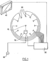
- the device is built around a series of analysis antennas or network of analysis probes 20 distributed in a circle around an antenna to be studied 10.
- the analysis antennas 20 are connected to a processing block 30, whose role is to transform the signals supplied by the antennas 20 into a video display signal.
- This video signal is proportional to the field radiated by the antenna under test in the direction of the analysis antenna.
- This video signal is transmitted on a display screen 40 shown at the top of the figure.
- the processing unit 30 is connected to a rotary motor 50 carrying the antenna to be studied 10, receiving from this motor 50 a positioning signal in order to deduce the relative positioning between the antenna to be studied and the antennas analysis 20.
- the assembly of these different survey plans allows the processing block to provide a three-dimensional visualization of the radiation pattern of the antenna to be studied, and to display this visualization on the screen 40.
- the walls of the chamber in which the antennas are located are not shown.
- the walls represented on the figure 2 form a closed enclosure and are each equipped for example with a multitude of pyramidal pins directed inwardly.
- FIG. 2 is schematically shown the positioning of an operator 70 in the chamber whose role here is to initially position the antenna 10 and change its positioning and / or adjust adjustment elements after radiation survey.
- the display screen 40 hitherto placed outside the chamber, typically in an external room only dedicated to computer processing, is here introduced into the chamber itself.
- the screen 40 allows the operator to observe in real time or slightly delayed the behavior of the antenna 10 which is directly within range.
- the operator can then perform a role that until then was not entrusted to him, that is to interpret the behavior of the antenna 10 (or any other electromagnetic tool) while manipulating the latter.
- This device allows the operator to modify and act on the antenna (or any other electromagnetic tool) and to visualize the resulting radiation pattern interactively.
- the operator 70 can simply change the geometry of the antenna 10, or its positioning in the chamber, for example its height or orientation, or adjustment parameters and interpret live effects of its interventions.
- the screen 40 is, for example, a flat screen liquid crystal or plasma, whose positioning against a vertical wall of the chamber is found to disturb only very slightly the radiation electromagnetic in it.
- the screen 40 can also be a conventional screen for optical projection (computer + projector).
- the viewing face of the screen for example the front face of a flat or cathode-ray tube monitor, in the plane of the wall of the chamber, avoiding the introduction of any foreign volume. in the bedroom.
- the present device In a variant where the study consists of analyzing the behavior of a mobile phone or any other portable electromagnetic device, and where it was customary to place the user of the telephone in the circle of antennas, in order to take account of the effect of the human body on radiation, the present device also has a certain advantage.
- an armrest is preferably provided with position adjustment means.
- These position adjustment means may be provided for adjustment only in height, or also for a height adjustment and horizontal displacement, for example in a forward / backward movement relative to the user, or lateral to it.
- These adjustment means are, according to a simplest variant, provided in the form of sliding guides fixed, after adjustment, using a series of immobilizing screws.
Claims (9)
- Aufbau zur Untersuchung des elektromagnetischen Verhaltes einer Antenne oder jedes anderen Sende- oder Empfangswerkzeugs von Wellen, umfassend:- einen reflexionsarmen Raum, der für den Empfang eines derartigen zu untersuchenden elektromagnetischen Werkzeugs (10) sowie einer Person, die dieses Werkzeug (10) bedient, vorgesehen ist, wobei der elektromagnetische Raum aufweist:∘ Wände, die ein geschlossenes Behältnis bilden, und∘ eine Anordung, welche die Entfernung eines elektromagnetischen Echos in dem reflexionsarmen Raum erlaubt;- mindestens eine Analyseantenne (20), die zum Einfangen der von dem zu untersuchenden elektromagnetischen Werkzeug (10) gesendeten oder empfangenen Wellen vorgesehen ist;- Verarbeitungsmittel (30) von Ausgangssignalen dieser Analyseantenne (20);- Anzeigemittel (40) eines für das zu untersuchende elektromagnetische Werkzeug (10) ermittelten Strahlungsdiagramms, die derart platziert sind, dass die Person, welche das zu untersuchende elektromagnetische Werkzeug (10) bedient, die Wirkung ihrer Bedienungen auf das elektromagnetische Verhalten dieses Werkzeugs (10) direkt beobachtet;dadurch gekennzeichnet, dass:die Anzeigemittel (40) des Strahlungsdiagramms vollkommen im Inneren des reflexionsarmen Raums platziert sind, undder reflexionsarme Raum einen Sitz umfasst, der die Person, welche das zu untersuchende Werkzeug (10) bedient, empfängt, und eine regulierbare Stützte für einen Arm dieser Person, wobei der Sitz und die regulierbare Stütze eine Neupositionierung der gesamten Person mit exakter Neupositionierung des Arms erlaubt, wodurch mehrere aufeinanderfolgende Verwendungen des zu untersuchenden elektromagnetischen Werkzeugs (10) in einer selben Position desselben in Bezug zum Rest des Körpers der Person ermöglicht werden.
- Untersuchungsaufbau nach erstem Anspruch, dadurch gekennzeichnet, dass er ein Netz von Analyseantennen (20) einschließt, die in einem Kreis angeordnet sind, der sich etwa um das zu analysierende elektromagnetische Objekt (10) erstreckt.
- Untersuchungsaufbau nach Anspruch 2, dadurch gekennzeichnet, dass er Mittel einschließt, die imstande sind, automatisch eine relative Rotation zwischen der Vielzahl von Analyseantennen im Kreis (20) und dem zu analysierenden elektromagnetischen Werkzeug (10) um eine Rotationsachse zu erzeugen, die etwa diametral zu dem von allen Analyseantennen (20) gebildeten Kreis ist.
- Untersuchungsaufbau nach einem der vorangehenden Ansprüche, dadurch gekennzeichnet, dass die Anzeigemittel (40) des Strahlungsdiagramms des zu untersuchenden Objekts (10) einen Bildschirm (40) einschließen, der auf einer Innenwand des reflexionsarmen Raums platziert ist.
- Untersuchungsaufbau nach einem der Ansprüche 1 bis 3, dadurch gekennzeichnet, dass die Anzeigemittel (40) des Strahlungsdiagramms des zu untersuchenden Objekts (10) Visualisierungsbrillen einschließen, die direkt auf der Person platziert sind, die das Werkzeug in dem reflexionsarmen Raum bedient, oder auch auf eine andere Person verlagert sind, die sich in dem reflexionsarmen Raum befindet.
- Untersuchungsaufbau nach Anspruch 4, dadurch gekennzeichnet, dass der Bildschirm (40) von der Betrachtungsseite eines Monitors oder von einem konventionellen Bildschirm für optische Projektion gebildet ist, wobei diese Seite etwa mit der Ebene einer der Wände des Raums fluchtet.
- Untersuchungsaufbau nach vorangehendem Anspruch, dadurch gekennzeichnet, dass der Bildschirm (40) von der Betrachtungsseite eines flachen Monitors (40), insbesondere eines Flüssigkristall- oder Plasmamonitors, gebildet ist.
- Untersuchungsaufbau nach Anspruch 6, dadurch gekennzeichnet, dass der Bildschirm (40) ein konventioneller Bildschirm für optische Projektion ist.
- Untersuchungsaufbau nach einem der vorangehenden Ansprüche, dadurch gekennzeichnet, dass das zu untersuchende elektromagnetische Werkzeug (10) ein Telefon ist.
Applications Claiming Priority (2)
| Application Number | Priority Date | Filing Date | Title |
|---|---|---|---|
| FR0309985A FR2859023B1 (fr) | 2003-08-18 | 2003-08-18 | Chambre anechoique a observation directe du comportement electromagnetique d'un outil a etudier |
| PCT/FR2004/002153 WO2005019844A1 (fr) | 2003-08-18 | 2004-08-18 | Chambre anechoïque a observation directe du comportement electromagnetique d’un outil a etudier |
Publications (2)
| Publication Number | Publication Date |
|---|---|
| EP1660895A1 EP1660895A1 (de) | 2006-05-31 |
| EP1660895B1 true EP1660895B1 (de) | 2018-07-25 |
Family
ID=34112802
Family Applications (1)
| Application Number | Title | Priority Date | Filing Date |
|---|---|---|---|
| EP04786319.6A Active EP1660895B1 (de) | 2003-08-18 | 2004-08-18 | Reflexionsarmer raum zur direkten betrachtung des emv-verhaltens einer zu untersuchenden einrichtung |
Country Status (7)
| Country | Link |
|---|---|
| US (1) | US7466142B2 (de) |
| EP (1) | EP1660895B1 (de) |
| JP (1) | JP4932482B2 (de) |
| CN (1) | CN1853110A (de) |
| CA (1) | CA2536022C (de) |
| FR (1) | FR2859023B1 (de) |
| WO (1) | WO2005019844A1 (de) |
Families Citing this family (7)
| Publication number | Priority date | Publication date | Assignee | Title |
|---|---|---|---|---|
| CN101039534B (zh) * | 2006-03-15 | 2012-06-20 | 鸿富锦精密工业(深圳)有限公司 | 声音检测设备和自动传送装置 |
| CN1964547A (zh) * | 2006-11-30 | 2007-05-16 | 中兴通讯股份有限公司 | 确定天线最小测试距离的方法 |
| JP2008241661A (ja) * | 2007-03-29 | 2008-10-09 | Fujitsu Ltd | Emi測定システム |
| US7830296B2 (en) * | 2007-07-11 | 2010-11-09 | Finisar Corporation | Anechoic structures for absorbing electromagnetic interference in a communications module |
| WO2009091087A1 (en) * | 2008-01-14 | 2009-07-23 | Ktm Technology Co., Ltd. | Hemi-spherical type antenna chamber |
| FR2927701B1 (fr) * | 2008-02-20 | 2010-04-09 | Satimo Sa | Dispositif et procede pour la determination d'au moins une grandeur associee au rayonnement electromagnetique d'un objet sous test. |
| US8462039B2 (en) * | 2009-12-09 | 2013-06-11 | Electronics And Telecommunications Research Institute | Indoor electromagnetic environment implementing structure and a constructing method thereof |
Family Cites Families (14)
| Publication number | Priority date | Publication date | Assignee | Title |
|---|---|---|---|---|
| JP2602872B2 (ja) * | 1988-01-20 | 1997-04-23 | 株式会社東芝 | 放射電磁界特性測定装置 |
| JP2574409B2 (ja) * | 1988-07-08 | 1997-01-22 | 松下電器産業株式会社 | Emc試験用電磁波無響室およびそのシールド材 |
| JPH06294833A (ja) * | 1993-04-08 | 1994-10-21 | Nippon Sheet Glass Co Ltd | アンテナ特性測定装置 |
| DE4316642A1 (de) * | 1993-05-18 | 1994-11-24 | Siemens Ag | Abschirmkammer mit einer nicht störenden und störunempfindlichen Monitor-Anzeigevorrichtung |
| JPH09114543A (ja) * | 1995-10-02 | 1997-05-02 | Xybernaut Corp | ハンドフリーコンピュータ装置 |
| JPH09101370A (ja) * | 1995-10-03 | 1997-04-15 | Fuji Electric Co Ltd | 椅子式ホールボディカウンタ |
| JPH11248772A (ja) * | 1998-02-27 | 1999-09-17 | Mitsubishi Electric Corp | マイクロ波通信機器用試験装置 |
| JP2000009776A (ja) * | 1998-06-22 | 2000-01-14 | Advantest Corp | 無線通信特性試験装置 |
| JP2000166656A (ja) * | 1998-12-11 | 2000-06-20 | Mitsubishi Electric Corp | 机 |
| FR2797327B1 (fr) * | 1999-08-03 | 2001-11-09 | France Telecom | Procede et dispositif de mesure en champ proche de rayonnements radioelectriques non controles |
| JP2002107396A (ja) * | 2000-09-29 | 2002-04-10 | Matsushita Electric Ind Co Ltd | 疑似人体とそれを用いた測定方法 |
| US6329953B1 (en) * | 2000-09-29 | 2001-12-11 | Rangestar Wireless | Method and system for rating antenna performance |
| JP2002251148A (ja) * | 2001-02-26 | 2002-09-06 | Fujitsu Kiden Ltd | 表示装置の設置方法 |
| DE60120792T2 (de) * | 2001-07-27 | 2007-06-14 | Advantest Corp. | Vorrichtung zur messung elektromagnetischer wellen |
-
2003
- 2003-08-18 FR FR0309985A patent/FR2859023B1/fr not_active Expired - Fee Related
-
2004
- 2004-08-18 JP JP2006523650A patent/JP4932482B2/ja active Active
- 2004-08-18 US US10/568,667 patent/US7466142B2/en active Active
- 2004-08-18 EP EP04786319.6A patent/EP1660895B1/de active Active
- 2004-08-18 WO PCT/FR2004/002153 patent/WO2005019844A1/fr active Application Filing
- 2004-08-18 CN CNA2004800270471A patent/CN1853110A/zh active Pending
- 2004-08-18 CA CA2536022A patent/CA2536022C/fr active Active
Non-Patent Citations (1)
| Title |
|---|
| None * |
Also Published As
| Publication number | Publication date |
|---|---|
| WO2005019844A1 (fr) | 2005-03-03 |
| CA2536022C (fr) | 2014-08-12 |
| US7466142B2 (en) | 2008-12-16 |
| EP1660895A1 (de) | 2006-05-31 |
| US20060208746A1 (en) | 2006-09-21 |
| CN1853110A (zh) | 2006-10-25 |
| JP4932482B2 (ja) | 2012-05-16 |
| FR2859023A1 (fr) | 2005-02-25 |
| JP2007502972A (ja) | 2007-02-15 |
| FR2859023B1 (fr) | 2005-12-23 |
| CA2536022A1 (fr) | 2005-03-03 |
Similar Documents
| Publication | Publication Date | Title |
|---|---|---|
| US11307285B2 (en) | Apparatus, system and method for spatially locating sound sources | |
| EP1660895B1 (de) | Reflexionsarmer raum zur direkten betrachtung des emv-verhaltens einer zu untersuchenden einrichtung | |
| US20160277719A1 (en) | Projection screen for specularly reflecting light | |
| Williams et al. | Volumetric acoustic vector intensity imager | |
| FR3001301A1 (de) | ||
| FR2609177A1 (fr) | Procede et appareil pour former acoustiquement des images de la paroi d'un trou de sonde | |
| CA2535933A1 (fr) | Dipositif de controle du debit d'absorption specifique d'objets rayonnants fabriques en serie | |
| EP3857380A1 (de) | Nicht intrusive automatisierte testbank zur durchführung mechanischer und/oder software- und/oder visueller und/oder audiotests an der mensch-maschine-schnittstelle eines geräts/einer vorrichtung | |
| WO2012045879A1 (fr) | Procede et dispositif de test electromagnetique d'un objet | |
| JP2021518569A (ja) | 音源の空間的位置の特定のための装置、システムおよび方法 | |
| Nowakowski et al. | Localization of acoustic sensors from passive Green's function estimation | |
| EP2825876B1 (de) | Ultraschall-array-sonde und verfahren zum herstellen einer solchen sonde, steuerungsverfahren einer solchen sonde und entsprechendes computerprogramm | |
| EP2182334B1 (de) | Vorrichtung zum Messen und Darstellen der Geräuschquellen innerhalb eines Raums | |
| CN106796447A (zh) | 安置在可移动表面上的对象的模型数据 | |
| FR2951563A1 (fr) | Procede et installation d'analyse de parametres geometriques d'un objet | |
| US20230243742A1 (en) | Small sample accessories for optical spectrometers | |
| EP1597601B1 (de) | Methode und system zur messung der spezifischen absorbtionsrate | |
| Hutt et al. | Reconstructing the shape of an object from its mirror image | |
| FR2871580A1 (fr) | Localisation d'une source de rayonnement electromagnetique sur un equipement electrique | |
| WO2003060588A1 (fr) | Procede et dispositif de visualisation microscopique a sondes locales d'un objet tridimensionnel | |
| Peck et al. | Influence of density on hyperspectral brdf signatures of granular materials | |
| Thompson et al. | Application of Acustic Cameras to Measurement and Tuning of an Orchestra Rehearsal Room | |
| CN114527505A (zh) | 薄层识别方法、装置、设备及存储介质 | |
| Rosell | New measurements techniques: Optical methods for characterizing sound fields | |
| FR3057987A1 (fr) | Systeme et procede pour s'entrainer a la manipulation d'une sonde echographique |
Legal Events
| Date | Code | Title | Description |
|---|---|---|---|
| PUAI | Public reference made under article 153(3) epc to a published international application that has entered the european phase |
Free format text: ORIGINAL CODE: 0009012 |
|
| 17P | Request for examination filed |
Effective date: 20060228 |
|
| AK | Designated contracting states |
Kind code of ref document: A1 Designated state(s): AT BE BG CH CY CZ DE DK EE ES FI FR GB GR HU IE IT LI LU MC NL PL PT RO SE SI SK TR |
|
| DAX | Request for extension of the european patent (deleted) | ||
| REG | Reference to a national code |
Ref country code: HK Ref legal event code: DE Ref document number: 1091269 Country of ref document: HK |
|
| 17Q | First examination report despatched |
Effective date: 20091007 |
|
| RAP1 | Party data changed (applicant data changed or rights of an application transferred) |
Owner name: MICROWAVE VISION |
|
| GRAP | Despatch of communication of intention to grant a patent |
Free format text: ORIGINAL CODE: EPIDOSNIGR1 |
|
| INTG | Intention to grant announced |
Effective date: 20180214 |
|
| GRAS | Grant fee paid |
Free format text: ORIGINAL CODE: EPIDOSNIGR3 |
|
| GRAA | (expected) grant |
Free format text: ORIGINAL CODE: 0009210 |
|
| REG | Reference to a national code |
Ref country code: DE Ref legal event code: R081 Ref document number: 602004052973 Country of ref document: DE Owner name: MICROWAVE VISION, FR Free format text: FORMER OWNER: STE D'APPLICATIONS TECHNOLOGIQUES DE L'IMAGERIE MICRO ONDES, LES ULIS, FR |
|
| AK | Designated contracting states |
Kind code of ref document: B1 Designated state(s): AT BE BG CH CY CZ DE DK EE ES FI FR GB GR HU IE IT LI LU MC NL PL PT RO SE SI SK TR |
|
| REG | Reference to a national code |
Ref country code: GB Ref legal event code: FG4D Free format text: NOT ENGLISH |
|
| REG | Reference to a national code |
Ref country code: CH Ref legal event code: EP |
|
| REG | Reference to a national code |
Ref country code: FR Ref legal event code: PLFP Year of fee payment: 15 |
|
| REG | Reference to a national code |
Ref country code: AT Ref legal event code: REF Ref document number: 1022336 Country of ref document: AT Kind code of ref document: T Effective date: 20180815 |
|
| REG | Reference to a national code |
Ref country code: IE Ref legal event code: FG4D Free format text: LANGUAGE OF EP DOCUMENT: FRENCH |
|
| REG | Reference to a national code |
Ref country code: DE Ref legal event code: R096 Ref document number: 602004052973 Country of ref document: DE |
|
| REG | Reference to a national code |
Ref country code: NL Ref legal event code: MP Effective date: 20180725 |
|
| PG25 | Lapsed in a contracting state [announced via postgrant information from national office to epo] |
Ref country code: NL Free format text: LAPSE BECAUSE OF FAILURE TO SUBMIT A TRANSLATION OF THE DESCRIPTION OR TO PAY THE FEE WITHIN THE PRESCRIBED TIME-LIMIT Effective date: 20180725 |
|
| REG | Reference to a national code |
Ref country code: AT Ref legal event code: MK05 Ref document number: 1022336 Country of ref document: AT Kind code of ref document: T Effective date: 20180725 |
|
| PG25 | Lapsed in a contracting state [announced via postgrant information from national office to epo] |
Ref country code: GR Free format text: LAPSE BECAUSE OF FAILURE TO SUBMIT A TRANSLATION OF THE DESCRIPTION OR TO PAY THE FEE WITHIN THE PRESCRIBED TIME-LIMIT Effective date: 20181026 Ref country code: AT Free format text: LAPSE BECAUSE OF FAILURE TO SUBMIT A TRANSLATION OF THE DESCRIPTION OR TO PAY THE FEE WITHIN THE PRESCRIBED TIME-LIMIT Effective date: 20180725 Ref country code: BG Free format text: LAPSE BECAUSE OF FAILURE TO SUBMIT A TRANSLATION OF THE DESCRIPTION OR TO PAY THE FEE WITHIN THE PRESCRIBED TIME-LIMIT Effective date: 20181025 Ref country code: FI Free format text: LAPSE BECAUSE OF FAILURE TO SUBMIT A TRANSLATION OF THE DESCRIPTION OR TO PAY THE FEE WITHIN THE PRESCRIBED TIME-LIMIT Effective date: 20180725 Ref country code: PL Free format text: LAPSE BECAUSE OF FAILURE TO SUBMIT A TRANSLATION OF THE DESCRIPTION OR TO PAY THE FEE WITHIN THE PRESCRIBED TIME-LIMIT Effective date: 20180725 Ref country code: SE Free format text: LAPSE BECAUSE OF FAILURE TO SUBMIT A TRANSLATION OF THE DESCRIPTION OR TO PAY THE FEE WITHIN THE PRESCRIBED TIME-LIMIT Effective date: 20180725 |
|
| PG25 | Lapsed in a contracting state [announced via postgrant information from national office to epo] |
Ref country code: ES Free format text: LAPSE BECAUSE OF FAILURE TO SUBMIT A TRANSLATION OF THE DESCRIPTION OR TO PAY THE FEE WITHIN THE PRESCRIBED TIME-LIMIT Effective date: 20180725 |
|
| REG | Reference to a national code |
Ref country code: CH Ref legal event code: PL |
|
| REG | Reference to a national code |
Ref country code: DE Ref legal event code: R097 Ref document number: 602004052973 Country of ref document: DE |
|
| PG25 | Lapsed in a contracting state [announced via postgrant information from national office to epo] |
Ref country code: EE Free format text: LAPSE BECAUSE OF FAILURE TO SUBMIT A TRANSLATION OF THE DESCRIPTION OR TO PAY THE FEE WITHIN THE PRESCRIBED TIME-LIMIT Effective date: 20180725 Ref country code: CH Free format text: LAPSE BECAUSE OF NON-PAYMENT OF DUE FEES Effective date: 20180831 Ref country code: LU Free format text: LAPSE BECAUSE OF NON-PAYMENT OF DUE FEES Effective date: 20180818 Ref country code: LI Free format text: LAPSE BECAUSE OF NON-PAYMENT OF DUE FEES Effective date: 20180831 Ref country code: MC Free format text: LAPSE BECAUSE OF FAILURE TO SUBMIT A TRANSLATION OF THE DESCRIPTION OR TO PAY THE FEE WITHIN THE PRESCRIBED TIME-LIMIT Effective date: 20180725 Ref country code: CZ Free format text: LAPSE BECAUSE OF FAILURE TO SUBMIT A TRANSLATION OF THE DESCRIPTION OR TO PAY THE FEE WITHIN THE PRESCRIBED TIME-LIMIT Effective date: 20180725 Ref country code: RO Free format text: LAPSE BECAUSE OF FAILURE TO SUBMIT A TRANSLATION OF THE DESCRIPTION OR TO PAY THE FEE WITHIN THE PRESCRIBED TIME-LIMIT Effective date: 20180725 |
|
| REG | Reference to a national code |
Ref country code: BE Ref legal event code: MM Effective date: 20180831 |
|
| REG | Reference to a national code |
Ref country code: IE Ref legal event code: MM4A |
|
| PG25 | Lapsed in a contracting state [announced via postgrant information from national office to epo] |
Ref country code: DK Free format text: LAPSE BECAUSE OF FAILURE TO SUBMIT A TRANSLATION OF THE DESCRIPTION OR TO PAY THE FEE WITHIN THE PRESCRIBED TIME-LIMIT Effective date: 20180725 Ref country code: SK Free format text: LAPSE BECAUSE OF FAILURE TO SUBMIT A TRANSLATION OF THE DESCRIPTION OR TO PAY THE FEE WITHIN THE PRESCRIBED TIME-LIMIT Effective date: 20180725 |
|
| PLBE | No opposition filed within time limit |
Free format text: ORIGINAL CODE: 0009261 |
|
| STAA | Information on the status of an ep patent application or granted ep patent |
Free format text: STATUS: NO OPPOSITION FILED WITHIN TIME LIMIT |
|
| 26N | No opposition filed |
Effective date: 20190426 |
|
| PG25 | Lapsed in a contracting state [announced via postgrant information from national office to epo] |
Ref country code: IE Free format text: LAPSE BECAUSE OF NON-PAYMENT OF DUE FEES Effective date: 20180818 |
|
| PG25 | Lapsed in a contracting state [announced via postgrant information from national office to epo] |
Ref country code: SI Free format text: LAPSE BECAUSE OF FAILURE TO SUBMIT A TRANSLATION OF THE DESCRIPTION OR TO PAY THE FEE WITHIN THE PRESCRIBED TIME-LIMIT Effective date: 20180725 Ref country code: BE Free format text: LAPSE BECAUSE OF NON-PAYMENT OF DUE FEES Effective date: 20180831 |
|
| PG25 | Lapsed in a contracting state [announced via postgrant information from national office to epo] |
Ref country code: TR Free format text: LAPSE BECAUSE OF FAILURE TO SUBMIT A TRANSLATION OF THE DESCRIPTION OR TO PAY THE FEE WITHIN THE PRESCRIBED TIME-LIMIT Effective date: 20180725 |
|
| PG25 | Lapsed in a contracting state [announced via postgrant information from national office to epo] |
Ref country code: HU Free format text: LAPSE BECAUSE OF FAILURE TO SUBMIT A TRANSLATION OF THE DESCRIPTION OR TO PAY THE FEE WITHIN THE PRESCRIBED TIME-LIMIT; INVALID AB INITIO Effective date: 20040818 Ref country code: PT Free format text: LAPSE BECAUSE OF FAILURE TO SUBMIT A TRANSLATION OF THE DESCRIPTION OR TO PAY THE FEE WITHIN THE PRESCRIBED TIME-LIMIT Effective date: 20180725 |
|
| PG25 | Lapsed in a contracting state [announced via postgrant information from national office to epo] |
Ref country code: CY Free format text: LAPSE BECAUSE OF FAILURE TO SUBMIT A TRANSLATION OF THE DESCRIPTION OR TO PAY THE FEE WITHIN THE PRESCRIBED TIME-LIMIT Effective date: 20180725 |
|
| REG | Reference to a national code |
Ref country code: DE Ref legal event code: R081 Ref document number: 602004052973 Country of ref document: DE Owner name: MICROWAVE VISION, FR Free format text: FORMER OWNER: MICROWAVE VISION, VILLEBON SUR YVETTE, FR |
|
| PGFP | Annual fee paid to national office [announced via postgrant information from national office to epo] |
Ref country code: IT Payment date: 20230809 Year of fee payment: 20 Ref country code: GB Payment date: 20230824 Year of fee payment: 20 |
|
| PGFP | Annual fee paid to national office [announced via postgrant information from national office to epo] |
Ref country code: FR Payment date: 20230710 Year of fee payment: 20 Ref country code: DE Payment date: 20230808 Year of fee payment: 20 |