EP1659866B1 - Fleischschneide- und zerlegevorrichtung - Google Patents
Fleischschneide- und zerlegevorrichtung Download PDFInfo
- Publication number
- EP1659866B1 EP1659866B1 EP04764139A EP04764139A EP1659866B1 EP 1659866 B1 EP1659866 B1 EP 1659866B1 EP 04764139 A EP04764139 A EP 04764139A EP 04764139 A EP04764139 A EP 04764139A EP 1659866 B1 EP1659866 B1 EP 1659866B1
- Authority
- EP
- European Patent Office
- Prior art keywords
- cutting
- trestle
- bench
- circular blade
- meat
- Prior art date
- Legal status (The legal status is an assumption and is not a legal conclusion. Google has not performed a legal analysis and makes no representation as to the accuracy of the status listed.)
- Expired - Lifetime
Links
- 238000005520 cutting process Methods 0.000 title claims abstract description 76
- 235000013372 meat Nutrition 0.000 title claims abstract description 26
- 241001465754 Metazoa Species 0.000 claims abstract description 4
- 239000000463 material Substances 0.000 claims description 20
- 230000001012 protector Effects 0.000 claims 2
- 230000003247 decreasing effect Effects 0.000 claims 1
- 238000007688 edging Methods 0.000 claims 1
- 229920002994 synthetic fiber Polymers 0.000 claims 1
- 230000005540 biological transmission Effects 0.000 description 4
- 210000000988 bone and bone Anatomy 0.000 description 4
- 210000001562 sternum Anatomy 0.000 description 4
- 210000002683 foot Anatomy 0.000 description 3
- 238000004519 manufacturing process Methods 0.000 description 3
- 238000000926 separation method Methods 0.000 description 3
- 241001494479 Pecora Species 0.000 description 2
- 241000282887 Suidae Species 0.000 description 2
- 229920003023 plastic Polymers 0.000 description 2
- 239000004033 plastic Substances 0.000 description 2
- 210000003371 toe Anatomy 0.000 description 2
- 208000010392 Bone Fractures Diseases 0.000 description 1
- 230000000712 assembly Effects 0.000 description 1
- 238000000429 assembly Methods 0.000 description 1
- 238000004140 cleaning Methods 0.000 description 1
- 230000007423 decrease Effects 0.000 description 1
- 230000002349 favourable effect Effects 0.000 description 1
- 238000007654 immersion Methods 0.000 description 1
- 238000003780 insertion Methods 0.000 description 1
- 230000037431 insertion Effects 0.000 description 1
- 238000009434 installation Methods 0.000 description 1
- 239000007788 liquid Substances 0.000 description 1
- 238000012423 maintenance Methods 0.000 description 1
- 230000013011 mating Effects 0.000 description 1
- 238000000034 method Methods 0.000 description 1
- 210000003049 pelvic bone Anatomy 0.000 description 1
- 238000003307 slaughter Methods 0.000 description 1
- 239000000725 suspension Substances 0.000 description 1
Images

Classifications
-
- A—HUMAN NECESSITIES
- A22—BUTCHERING; MEAT TREATMENT; PROCESSING POULTRY OR FISH
- A22B—SLAUGHTERING
- A22B5/00—Accessories for use during or after slaughtering
- A22B5/0017—Apparatus for cutting, dividing or deboning carcasses
- A22B5/0029—Cutting through or detaching portions of a carcass
-
- A—HUMAN NECESSITIES
- A22—BUTCHERING; MEAT TREATMENT; PROCESSING POULTRY OR FISH
- A22C—PROCESSING MEAT, POULTRY, OR FISH
- A22C17/00—Other devices for processing meat or bones
- A22C17/02—Apparatus for holding meat or bones while cutting
Definitions
- the invention relates to a meat cutting device and cutting device for cutting animal Schneidgut, with a mounted on a frame cutting table and arranged thereon, a substantially circular, rotatable about a rotation axis in a vertical cutting plane and depth adjustable with a pivot plate circular blade, wherein a motor with a flanged Transmission is drivingly connected to the rotation axis and is arranged laterally above the axis of rotation on a pivot arm which is held in a Abtement Scheme behind the circular blade on the frame.
- Such a meat cutting device is known from the patent DE 195 17 636 C2. Die.Hier described device has an awkward to use and thus dangerous height adjustment of the cutting disc. Also, the machine frame is arranged relatively wide in Abrus Scheme the cut meat, thus hindering a liquid operation. From this patent, a feeder carriage and mudguards are also known. Also known is a stop for the cut material.
- Such a meat cutting device and cutting device is also known from DE 295 21981 U1.
- This device was for the disassembly of larger animals, such as sheep, young pigs, only limited suitability, since the holder of the circular blade in the Abrus Scheme the cut material extended over 20-30 cm.
- the cutting material on the cutting table had to be removed by pushing it, which might require the use of a helper.
- the dismantling of hanging conveyors od.
- Hung carcasses especially the separation of the sternum, the separation of the horns, the head, the legs, paws and toes, the opening of the pelvic bone, the halving, called columns, and the nipping of ribs is made with motor-driven circular saws, which are guided by hand or to a robot arm.
- Such circular saws are from the brochure: FRIEND, catalog 2003/2004, p 8, 10 - 16,20,22-24, known.
- the gear motor on whose axis the circular saw blade is flanged, is provided with two handles and possibly a suspension loop and / or a robot connection. The cuts of the circular saw produce rough cut edges, substantial material losses, and the bone sawdust undesirably contaminates the meat.
- the arrangement of the narrow pivot arm, on which the motor, the gear and the circular blade are arranged, in the feed direction and the insertion of the splitting wedge in the intermediate region between the circular blade and the pivot arm provide a stawless removal of the separated cut material.
- Roller conveyors or a conveyor belt are advantageously arranged on the cutting table, which passively or actively facilitate the removal of the material to be cut.
- supply side is longitudinal or transverse to put a roller conveyor or a belt conveyor on the cutting table, as far as there is not a feed carriage is sufficient.
- the feeder carriage may be equipped with a gap receiving the circular blade, a feed edge for the cut-off part and various holding troughs.
- All accessories that are used to feed and discharge such as feed table, roller conveyors, conveyor belts, stop of the material to be cut, are laterally supported on the frame and swung off, so that an easy cleaning and switching with changing cutting material is immediately possible.
- the frame is equipped with height-adjustable feet so that it can be adapted to different operator sizes and possibly the height of infeed or outfeed belts.
- the frame and the circular blade drive are for one left-handed and one prepared right-handed installation, so that the device is easy to bring in different production lines.
- the circular blade is largely surrounded by a knife guard with plastic trim divided into sectors, so that circular knives of different diameters; when regrinding, it decreases; always optimally protected against access.
- the cutting speed of the circumference of the circumference of the circular knife is determined by the diameter of the circular knife and the speed so that a smooth meat edge is produced during rapid work and a smooth splitting of bone takes place with bone fracture as small as possible.
- the diameter of the circular knife is expediently between 100 and 1,000 mm, is chosen for work that also lead into the interior of the carcass, smaller than in pure outdoor work.
- the mounting flange of the circular knife is as flat as possible and without edges and corners, so that the cut material can slide unimpeded sideways past.
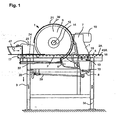
- Fig. 1 shows a table frame 3 with screws 33, height adjustable feet 34 and a cutting table 2, in which a cutting device 1 protrudes, which consists of a circular blade 6, the center of which is held on a drive axle 12 with a flange 14, which via a transmission is drivingly connected to an overhead motor 10.
- the motor 10, the gear 11 and the circular blade 6 are held ab complicat document at an upper stator portion 7 of a pivot arm 8, which is flat and is mounted in the direction of extension of the circular blade 6 about this in alignment with the pivot bearing 19 on the frame 3.
- the pivot arm 8 extends to half the height of the frame into the frame 3 and is there penetrated and clamped in circular-shaped cutouts of locking screws 13.
- the lower Schwenkarmende is coupled with a hinge to a threaded spindle, the front side mounted on the frame 3 in a mating thread and front accessible with a handwheel.
- the locking screws 13 are led out to the frame side, so that they can be easily solved and fixed for the adjustment of the immersion angle of the circular blade 6 in the table surface.
- a riving knife 9 is arranged, which is adjustable to narrow gap to the knife 6.
- the cutting table 2 is covered on its table surface 4 with a roller conveyor 43A.
- a feed carriage 24 is mounted with a slider 23 and a trough 47 for the cutting material 28 to be supplied, so that a lateral pivoting is possible.
- the circular blade 6 is surrounded on the top side and on the carriage side by a knife guard 21.
- the transport direction extends from the operating side 17 via the removal region 2A to the table rear side 16.
- the tilt adjustment of the cutting mechanism is indicated by the arrow 39.
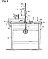
- Fig. 2 shows a front view of the cutting device. It can be seen the central division 18 of the cutting table 2 and the mounted on both sides of the table top roller conveyors 43A, 43B.
- the drive shaft 12 of the circular blade extends into the gear 11, which is held above the cutting work area on the narrow pivot arm 8, 7.
- To the circular blade 6 of the knife guard 21 is disposed above the transmission 11, which is removed at the front, so that you can see the inner edge side assembly with radially adjustable Kunststoffstollsektoren 50.
- the feed carriage 24 On the left in the image of the circular blade 6, the feed carriage 24 can be seen, the u.a. is guided on the guide rod 32 in the cutting and conveying direction.
- a guide rod 46 On the guide carriage 24 is transverse to the cutting direction, a guide rod 46, on which a cross slide 32 is slidably mounted, which is provided with a handle 25.
- the slide can be swung forwards and is used in particular when the material to be cut 28 is to be presented piece by piece or the slider 23 serves as a hold-down for the material to be cut 28, as shown.
- the feed carriage 24 also has a handle 25 and a slot recess or pocket 27 into which the circular knife 6 retracts when the carriage is advanced. On the side remote from the handle 25 to the recess 27, a feed edge 26 is arranged, which conveys the cut good a bit further.
- a guide rod 37 is arranged transversely to the conveying direction 37 on the frame 3, on which a stopper 35 is slidably mounted and fixable with the toggle 40.
- the stop 35 carries a longitudinally displaceable stop plate 36 which is fixed with clamping screws 38. Details of this are shown in FIG. 3 in a plan view of the displaceable assemblies 24, 23, 35.
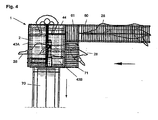
- Fig. 4 shows an arrangement of the device 1, in a production line with a feed and a discharge conveyor 60, 61, 70.
- the cut material 28 passes from the feed conveyor 60 via a short adjustment conveyor 61 from the left of the operator on a narrow cross conveyor 44 on the cutting table 2, so that the operator can easily advance the object to the cutting gap and beyond. He then pushes it onto the roller conveyors 43A, 43B oriented in the discharge device as well as the shoulder roller track 71 onto the discharge belt 70.
- the conveyor tracks can be equipped with passive or actively driven rollers or chain drives.
Landscapes
- Life Sciences & Earth Sciences (AREA)
- Engineering & Computer Science (AREA)
- Food Science & Technology (AREA)
- Wood Science & Technology (AREA)
- Zoology (AREA)
- Processing Of Meat And Fish (AREA)
- Crushing And Pulverization Processes (AREA)
- Processing Of Solid Wastes (AREA)
Description
- Die Erfindung betrifft eine Fleischschneidevorrichtung und Zerlegevorrichtung zum Zerteilen von tierischem Schneidgut, mit einem auf einem Gestell montierten Schneidetisch und einem darauf angeordneten, im wesentlichen kreisförmigen, um eine Rotationsachse in einer vertikalen Schneidebene rotierbaren und mit einem Schwenksteller tiefenverstellbaren Kreismesser, wobei ein Motor mit einem angeflanschten Getriebe mit der Rotationsachse antriebsmäßig verbunden ist und seitlich oberhalb der Rotationsachse an einem Schwenkarm angeordnet ist, der in einem Abförderbereich hinter dem Kreismesser an dem Gestell gehalten ist.
- Eine derartige Fleischschneidevorrichtung ist aus dem Patent DE 195 17 636 C2 bekannt. Die.hier beschriebene Vorrichtung weist eine nur umständlich zu bedienende und damit gefahrenträchtige Höhenverstellung der Schneidscheibe auf. Auch ist der Maschinenträger relativ breit im Abförderbereich des geschnittenen Fleisches angeordnet und behindert damit eine flüssige Arbeitsweise. Aus diesem Patent sind auch ein Zuführschlitten und Schutzbleche bekannt. Bekannt ist auch ein Anschlag für die das Schneidgut.
- Weiterhin ist eine derartige Fleischschneidevorrichtung und Zerlegevorrichtung auch aus der DE 295 21981 U1 bekannt. Diese Vorrichtung war für das Zerlegen größerer Tiere, wie Schafe, Jungschweine, nur beschränkt geeignet, da die Halterung des Kreismessers sich im Abförderbereich des Schneidgutes über 20-30 cm erstreckte. Zudem war zwischen dem Kreismesser und dem abförderseitig liegenden Schwenkarm ein Freiraum, in den ein ungeschützter Zugriff auf den Schneidkranz möglich war. Außerdem musste das Schneidgut auf dem Schneidtisch durch Schieben abgefördert werden, was u.U. den Einsatz einer Hilfsperson erforderte.
- Die Zerlegung von an Hängeförderern od. dgl. aufgehängten Tierkörpern, insbesondere das Trennen des Brustbeines, das Abtrennen der Hörner, des Kopfes, der Beine, Pfoten und Zehen, das Öffnen des Schloßbeines, das Halbieren, Spalten genannt, und das Abseiteln von Rippen wird mit motorgetriebenen Kreissägen vorgenommen, die von Hand oder zu einem Roboterarm geführt sind. Derartige Kreissägen sind aus dem Prospekt: FREUND, Katalog 2003/2004, S. 8, 10 - 16,20,22-24, bekannt. Der Getriebemotor, an dessen Achse das Kreissägeblatt angeflanscht ist, ist mit zwei Handgriffen und ggf. einer Aufhängeöse und/oder einem Roboteranschluss versehen. Die Schnitte der Kreissäge erzeugen rauhe Schnittkanten, erhebliche Materialverluste, und das Knochensägemehl kontaminiert das Fleisch in unerwünschter Weise.
- Da der hängende Tierkörper nur einen mäßigen Gegenhalt gegen Querkräfte bietet, weicht er häufig einer geraden Schnittfführung aus, wenn diese mittig durch Knochen, z. B. das Brustbein, führen soll. Die Handführung der Kreissäge in der Schnittrichtung durch den außer bei der Schlachtung gewöhnlich auf 1 - 2°C abgekühlten Tierkörper erfordert einen erheblichen Kraftaufwand.
- Es ist Aufgabe der Erfindung, eine Fleischschneidevorrichtung und Zerlegevorrichtung auf einem Schneidetisch zu schaffen, die die vorstehend genannten Nachteile der bekannten Fleischschneidevorrichtungen nicht aufweist. Weiterhin soll eine vorteilhafte Schnittqualität und hohe Standzeit des Schneidwerkzeuges auch für eine Vorrichtung zum Zerlegen von hängenden Tierkörpern mit einer besseren Schnittführungstreue und einer leichtere Handhabung erreicht werden.
- Zur Lösung dieser Aufgabe wird eine Vorrichtung gemäß Anspruch 1 vorgeschlagen
- Vorteilhafte Ausgestaltungen sind in den Unteransprüchen angegeben.
- Die Anordnung des schmalen Schwenkarmes, an dem der Motor, das Getriebe und das Kreismesser angeordnet sind, in der Vorschubrichtung sowie die Einfügung des Spaltkeiles in den Zwischenbereich zwischen dem Kreismesser und dem Schwenkarm erbringen ein stauloses Abfördern des abgeteilten Schneidgutes.
- Vorteilhaft werden Rollenbahnen oder ein Förderband auf dem Schneidtisch angeordnet, die passiv oder aktiv den Abtransport des Schneidgutes erleichtern.
- Auch zuführseitig ist längs oder quer eine Rollenbahn oder ein Bandförderer auf den Schneidtisch zu setzen, soweit dort nicht ein Zuführschlitten ausreichend ist.
- Der Zuführschlitten kann mit einem das Kreismesser aufnehmenden Spalt, einer Vorschubkante für das abgeschnittene Teil und verschiedenen Haltemulden ausgestattet sein.
- Alle Zubehörteile, die der Zu- und Abförderung dienen, wie Zuführtisch, Rollenbahnen, Förderbänder, Anschlag des Schneidgutes, sind seitlich am Gestell gehaltert und abschwenkbar, so dass eine einfache Reinigung und eine Umstellung bei wechselndem Schneidgut unmittelbar möglich ist.
- Das Gestell ist mit höhenverstellbaren Füßen versehen, damit es an verschiedene Bedienergrößen und eventuell die Höhe von Zu- oder Abführbändern anpassbar ist. Das Gestell und der Kreismesserantrieb sind für einen linkshändischen und einen rechtshändischen Einbau vorbereitet, so dass die Vorrichtung zwanglos in unterschiedliche Produktionslinien einzubringen ist.
- Vorteilhaft ist das Kreismesser mit einem Messerschutz mit in Sektoren gegliedertem Kunststoffbesatz weitgehend umgeben, so dass Kreismesser unterschiedlichen Durchmessers; beim Nachschleifen nimmt er ab; immer optimal vor dem Zugriff geschützt ist.
- Die Verwendung von Kreismessern für das Zerteilen von Fleisch hat sich wegen des äußerst geringen Verlustes bewährt. Für das Zerlegen von Schafen, Schweinen etc. in Vorder- und Hinterhälften, wobei auch Knochen durchteilt werden müssen, hat sich ein Kreismesser ähnlich bewährt, das von dem Einspannflansch aus bis zum keilförmigen Messerschliff hin eine stetig verjüngte Dicke aufweist.
- Die Schnittgeschwindigkeit des Kreismesserumfangs wird durch den Kreismesserdurchmesser und die Drehzahl so bestimmt, dass bei zügigem Arbeiten ein glatter Fleischrand erzeugt wird und eine glatte Spaltung von Knochen bei möglichst geringen Knochenanbruch erfolgt.
- Der Durchmesser des Kreismessers; er liegt zweckmäßig zwischen 100 und 1.000 mm, wird für Arbeiten, die auch ins Innere des Tierkörpers führen, kleiner als bei reinen Außenarbeiten gewählt.
- Der leichtere Angriff des Kreismessers auf das Material verleiht ihm eine mehrfach höhere Standzeit als es ein Kreissägeblatt unter gleichen Verhältnissen aufweist. Die höhere Standzeit vermindert die Rüst- und Wartungszeiten.
- Für die unterschiedlichen Zerlegearbeiten, wie
- Brustbeinteilen,
- Hornabschneiden,
- Beine, Pfoten, Zehen abtrennen,
- Schloßbeinspalten,
- Halbieren eines Tierkörpers,
- Nacken und Kopf ablösen,
- Rippen schneiden,
- Abvierteln,
- Der Befestigungsflansch des Kreismessers ist möglichst flach und ohne Kanten und Ecken ausgebildet, damit das geschnittene Material seitlich ungehemmt vorbei gleiten kann.
- Vorteilhafte Ausgestaltungen sind in den Figuren 1-4 dargestellt.
- Fig. 1
- zeigt eine Seitenansicht der Schneidvorrichtung;
- Fig. 2
- zeigt eine Frontansicht der Schneidvorrichtung;
- Fig. 3
- zeigt einen zuführseitigen Ausschnitt.
- Fig. 4
- zeigt eine Anordnung in einer Produktionsstraße in Draufsicht.
- Fig. 1 zeigt ein Tischgestell 3 mit Stellschrauben 33, höhenverstellbaren Füßen 34 und einem Schneidetisch 2, in den eine Schneidvorrichtung 1 hineinragt, die aus einem Kreismesser 6 besteht, dessen Zentrum auf einer Antriebsachse 12 mit einem Flansch 14 gehalten ist, die über ein Getriebe mit einem oben liegenden Motor 10 antriebsmäßig verbunden ist. Der Motor 10, das Getriebe 11 und das Kreismesser 6 sind an einem oberen Ständerbereich 7 eines Schwenkarmes 8 abförderseitig gehalten, der flach ausgebildet ist und in der Erstreckungsrichtung des Kreismessers 6 etwa mit diesem fluchtend im Schwenklager 19 am Gestell 3 gelagert ist. Der Schwenkarm 8 erstreckt sich bis zur halben Gestellhöhe in das Gestell 3 hinein und ist dort in kreisbogenförmigen Ausschnitten von Feststellschrauben 13 durchsetzt und eingeklemmt. Das untere Schwenkarmende ist mit einem Gelenk an eine Gewindespindel angekoppelt, die frontseitig am Gestell 3 in einem Gegengewinde gelagert und frontseitig zugänglich mit einem Handrad bestückt ist. Die Feststellschrauben 13 sind bis zur Gestellseite herausgeführt, so dass sie für das Verstellen des Eintauchwinkels des Kreismessers 6 in die Tischfläche leicht gelöst und fixiert werden können.
- Zwischen dem Schwenkarm 8 und dem Rand des Kreismessers 6 ist ein Spaltkeil 9 angeordnet, der auf engen Spalt zum Messer 6 einstellbar ist.
- Der Schneidetisch 2 ist auf seiner Tischfläche 4 mit einer Rollenbahn 43A belegt. Auf dem Schneidetisch 2 und an einer seitlich am Gestell 3 angeordneten Schlittenführungsstange 32 ist ein Zuführschlitten 24 mit einem Schieber 23 und einer Mulde 47 für das zuzuführende Schneidegut 28 gelagert, so dass auch ein seitliches Abschwenken möglich ist.
- Das Kreismesser 6 ist obenseitig und auf der Schlittenseite von einem Messerschutz 21 umgeben.
- Die Transportrichtung erstreckt sich von der Bedienseite 17 über den Abförderbereich 2A zur Tischrückseite 16. Die Neigungsverstellung des Schneidwerkes ist mit dem Pfeil 39 bezeichnet.
- Fig. 2 zeigt eine Frontansicht der Zerlegevorrichtung. Man erkennt die mittige Teilung 18 des Schneidtisches 2 und die beidseitig auf der Tischplatte aufgesetzten Rollenbahnen 43A, 43B. Die Antriebsachse 12 des Kreismessers erstreckt sich in das Getriebe 11, das oberhalb des Schneid-Arbeitsbereichs an dem schmalen Schwenkarm 8, 7 gehalten ist. Um das Kreismesser 6 ist der Messerschutz 21 oberhalb des Getriebes 11 angeordnet, der vorne abgenommen ist, so dass man die innere randseitige Bestückung mit radial verstellbaren Kunststollsektoren 50 erkennen kann.
- Links im Bild von dem Kreismesser 6 ist der Zuführschlitten 24 zu sehen, der u.a. an der Führungsstange 32 in der Schneid- und Förderrichtung geführt ist. An dem Führungsschlitten 24 befindet sich quer zur Schneidrichtung eine Führungsstange 46, auf der ein Querschieber 32 verschieblich gelagert ist, der mit einem Handgriff 25 versehen ist. Der Schieber ist nach vorne abschwenkbar und kommt insbesondere dann zum Einsatz, wenn das Schneidgut 28 Stück für Stück vorgelegt werden soll oder der Schieber 23 als Niederhalter für das Schneidgut 28, wie dargestellt, dient.
- Der Zuführschlitten 24 weist ebenfalls einen Handgriff 25 auf und eine Schlitzausnehmung oder Tasche 27, in die das Kreismesser 6 einfährt, wenn der Schlitten vorgeschoben wird. Auf der zum Handgriff 25 abgelegenen Seite der Ausnehmung 27 ist eine Vorschubkante 26 angeordnet, die das abgeschnittene Gut noch ein Stück weiterbefördert.
- Rechts im Bild von dem Kreismesser 6 ist quer zur Förderrichtung eine Führungsstange 37 am Gestell 3 angeordnet, auf dem ein Anschlag 35 verschieblich und mit dem Knebel 40 festlegbar gelagert ist. Der Anschlag 35 trägt eine längs verschiebliche Anschlagplatte 36, die mit Klemmschrauben 38 festlegbar ist.
Einzelheiten dazu zeigt Fig. 3 in einer Draufsicht auf die verschieblichen Baugruppen 24, 23, 35. - Fig. 4 zeigt eine Anordnung der Vorrichtung 1, in einer Produktionsstraße mit einem Zu- und einem Abförderer 60, 61, 70. Das Schneidgut 28 läuft vom Zuförderer 60 über einen kurzen Anpassungsförderer 61 von links des Bedieners auf einem schmalen Querförderer 44 auf den Schneidtisch 2, so dass der Bediener das Objekt bis zum Schneidspalt und darüber hinaus leicht vorschieben kann. Dann schiebt er es auf den in der Abfördervorrichtung orientierten Rollenbahnen 43A, 43B sowie die Ansatzrollenbahn 71 auf das Abförderband 70. Die Förderbahnen können mit passiven oder aktiv getriebenen Rollen oder mit Kettenantrieben bestückt sein.
-
- 1
- Schneidevorrichtung
- 2
- Schneidetisch
- 2A
- Abförderbereich
- 3
- Gestell
- 4
- Tischfläche (Rollenbahn/Transportband)
- 6
- Kreismesser
- 6A
- Messerkante
- 7
- Ständer
- 7A
- Ständer, oberes Ende
- 8
- Schwenkarm
- 9
- einstellbarer Spaltkeil (Berührungsschutz)
- 10
- Elektromotor
- 11
- Getriebe
- 12
- Antriebsachse mit Spannmutter
- 13
- Klemmschrauben
- 14
- Flansch
- 16
- Rückseite Tisch
- 17
- Bedienseite
- 18
- Schlitz in 4
- 19
- Schwenkachse für Schnitttiefenverstellung
- 20
- Handrad für Schnittiefenverstellung
- 21
- Messerschutz
- 23
- Schieber/Niederhalter, wegschwenkbar
- 24
- Zuführschlitten
- 25
- Handgriff
- 26
- Vorschubkante für Schneidgut
- 26A
- Handschutzblech
- 27
- Tasche / Schlitzaufnehmung
- 28
- Schneidgut
- 29
- Gewindespindel-Höhenverstellung
- 32
- Schlittenführung
- 33
- Feststellschraube
- 34
- höhenverstellbare Füße
- 35
- Anschlag für Schneidgut
- 36
- Anschlag längs einstellbar
- 37
- Führungsstange
- 38
- Klemmschraube
- 39
- Schnitttiefen-Einstellung
- 40
- Feststellschraube
- 43A
- Rollenbahn
- 43B
- Rollenbahn
- 44
- Querrollenbahn
- 45A
- muldenartiger Bereich
- 46
- Führungsstange
- 47
- Mulde
- 50
- Kunststoffsektorbesatz
- 60
- Zuförderer
- 61
- Abförderer
- 70
- Abförderbahn
- 71
- Ansatzrollenbahn
Claims (15)
- Fleischschneidevorrichtung und Zerlegevorrichtung (1) zum Zerteilen von tierischem Schneidgut (28), mit einem auf einem Gestell (3) montierten Schneidetisch (2) und einem darauf angeordneten, im wesentlichen kreisförmigen, um eine Rotationsachse (12) in einer vertikalen Schneidebene rotierbaren und mit einem Schwenksteller (29) tiefenverstellbaren Kreismesser (6), wobei ein Motor (10) mit einem angeflanschten Getriebe (11) mit der Rotationsachse (12) antriebsmäßig verbunden ist und seitlich oberhalb der Rotationsachse (12) an einem Schwenkarm (8) angeordnet ist, der in einem Abförderbereich (2A) hinter dem Kreismesser (6) an dem Gestell gehalten ist, dadurch gekennzeichnet,
dass der Schwenkarm (8) schmal ausgebildet ist und sich zumindest annähernd fluchtend zum Kreismesser (6) erstreckt
und
mit einem Schwenkgelenk (19) an dem Schneidetisch (2) am Gestell (3) gelagert ist und unterhalb des Schneidetisches (2) jeweils schwergängig und/oder lösbar fixiert gehalten ist und
dass der Schwenksteller (29) des Schwenkarmes (8) ein Spindelantrieb (29) ist, der gelenkig mit dem Schwenkarm (8) verbunden ist und
der von einer Bedienseite (17) des Schneidetisches (2) aus bedienbar ist, und
dass in einem Bereich zwischen dem Schwenkarm (8) und dem Kreismesser (6) ein dazu auf engen Spalt einstellbarer Spaltkeil (9) somit diesen Bereich fast vollständig ausfüllend angeordnet ist. - Fleischschneidevorrichtung nach Anspruch 1, dadurch gekennzeichnet, dass der Spindelantrieb (29) mit einem Handrad (20) bedienbar ist.
- Fleischschneidevorrichtung nach Anspruch 1, dadurch gekennzeichnet, dass der Schwenkarm (8) mit dem Gestell (3) durch Klemmschrauben (13) zusammengehalten ist, die jeweils konzentrisch um das Schwenklager (19) angeordnete Kreisbogenäusnehmungen durchsetzen und sich mit ihrem Kopf bis randseitig an das Gestell (3) erstrecken.
- Fleischschneidevorrichtung nach Anspruch 1, dadurch gekennzeichnet, dass auf dem Schneidetisch (2) ein Zuführschlitten (24) mit einem Handgriff (25) verschieblich gelagert ist, der eine schlitzförmige Ausnehmung (27) aufweist, durch die vorgeschoben das Kreismesser (6) hindurch tritt und seitlich von der mindestens ein Handschutzblech (26A) und ggf. abseits des Handgriffs (25) eine Vorschubkante (26) für das Schneidgut (28) angeordnet sind.
- Fleischschneidevorrichtung nach Anspruch 4, dadurch gekennzeichnet, dass der Schneidetisch (2) oder der Zuführschlitten (24) ein- oder beidseitig des Kreismessers (6) mit je einer Rollenbahn (43A, 43B) oder einem Förderband belegt ist.
- Fleischschneidevorrichtung nach Anspruch 4, dadurch gekennzeichnet, dass der Zuführschlitten (24) an einer Führungsstange (32), die seitlich am Gestell (3) angeordnet ist, einseitig geführt ist und um die Führungsstange (32) auf dem Schneidetisch (2) und neben diesem herabhängend verschwenkbar ist.
- Fleischschneidevorrichtung nach Anspruch 4, dadurch gekennzeichnet, dass der Zuführschlitten (24) ein- oder beidseitig der schlitzförmigen Ausnehmung (27) eine Schneidgut (28) aufnehmende Mulde (47) aufweist oder dass ein ausnehmungsnaher Bereich muldenartig ausgebildet ist und/oder die schlitzförmige Ausnehmung (27) des Zufuhrschlittens (24) eine schneidgut-spezifisch unterschiedliche Weite aufweist.
- Fleischschneidevorrichtung nach Anspruch 7, dadurch gekennzeichnet, dass an dem Zuführschlitten (24) frontseitig eine Querstange (46) angebracht ist, an der verschieblich und verschwenkbar ein Schieber und Niederhalter (23) gelagert ist, der einen Handgriff (25A) trägt.
- Fleischschneidevorrichtung nach Anspruch 4, dadurch gekennzeichnet, dass frontseitig am Gestell (2) abseitig des Zuführschlittens (24) eine Führungsstange (37) horizontal angeordnet ist, auf der ein Anschlag (35, 36) für das Schneidgut (28) verschieblich und festlegbar sowie abschwenkbar und auf den Schneidetisch (2) auflegbar gelagert ist.
- Fleischschneidevorrichtung nach Anspruch 1, dadurch gekennzeichnet, dass das Kreismesser (6) einem zentralen Befestigungsflansch (14) aus einer radial abnehmenden Dicke aufweist und randseitig in eine spitze Messerkante (6A) ausläuft.
- Fleischschneidevorrichtung nach Anspruch 1, dadurch gekennzeichnet, dass das Kreismesser (6) von einem teilkreisförmigen Messerschutz (21) umgeben ist, der auf seinem entlang einer Messerkante (6A) gelegenen Bereich mit einem konkav profilierten, sektormäßig gegliederten Kunststoffbesatz (50) an verschiedene Kreismesserdurchmesser eng anpassbar radial einstellbar bestückt ist.
- Fleischschneidevorrichtung nach Anspruch 5, dadurch gekennzeichnet, dass mindestens eine der Rollenbahnen (43A, 43B) mit losen oder angetriebenen Rollen bestückt ist.
- Fleischschneidevorrichtung nach Anspruch 5, dadurch gekennzeichnet, dass auf dem Schneidetisch (2) auf einem Bedienbereich eine Querrollenbahn (44) mit längsgerichteten Rollen angeordnet ist.
- Fleischschneidevorrichtung nach. Anspruch 5, dadurch gekennzeichnet, dass die Rollenbahnen (43A, 43B, 44) abschwenkbar und lösbar an dem Gestell (3) gelagert sind.
- Fleischschneidevorrichtung nach Anspruch 9, dadurch gekennzeichnet, dass der Zuführschlitten (24), der Anschlag (35, 36), der Motor (10) mit dem Getriebe (11) sowie ein Messerschutz (21) wahlweise rechtshändig und linkshändig auf dementsprechend vorbereiteten Gestell (3) anzuordnen sind.
Priority Applications (1)
| Application Number | Priority Date | Filing Date | Title |
|---|---|---|---|
| PL04764139T PL1659866T3 (pl) | 2003-08-21 | 2004-08-14 | Urządzenie do krojenia i rozbioru mięsa |
Applications Claiming Priority (3)
| Application Number | Priority Date | Filing Date | Title |
|---|---|---|---|
| DE10338336A DE10338336B3 (de) | 2003-08-21 | 2003-08-21 | Fleischschneide- und Zerlegevorrichtung |
| DE102004024077A DE102004024077A1 (de) | 2004-05-13 | 2004-05-13 | Vorrichtung zum Zerlegen von Tierkörpern |
| PCT/EP2004/009147 WO2005020692A2 (de) | 2003-08-21 | 2004-08-14 | Fleischschneide- und zerlegevorrichtung |
Publications (2)
| Publication Number | Publication Date |
|---|---|
| EP1659866A2 EP1659866A2 (de) | 2006-05-31 |
| EP1659866B1 true EP1659866B1 (de) | 2007-04-18 |
Family
ID=34276510
Family Applications (1)
| Application Number | Title | Priority Date | Filing Date |
|---|---|---|---|
| EP04764139A Expired - Lifetime EP1659866B1 (de) | 2003-08-21 | 2004-08-14 | Fleischschneide- und zerlegevorrichtung |
Country Status (10)
| Country | Link |
|---|---|
| US (1) | US20070032185A1 (de) |
| EP (1) | EP1659866B1 (de) |
| AT (1) | ATE359712T1 (de) |
| AU (1) | AU2004267934B2 (de) |
| DE (1) | DE502004003561D1 (de) |
| DK (1) | DK1659866T3 (de) |
| ES (1) | ES2284048T3 (de) |
| NZ (1) | NZ545780A (de) |
| PL (1) | PL1659866T3 (de) |
| WO (1) | WO2005020692A2 (de) |
Families Citing this family (13)
| Publication number | Priority date | Publication date | Assignee | Title |
|---|---|---|---|---|
| DE202010000260U1 (de) * | 2010-02-26 | 2010-06-02 | Freund Maschinenfabrik Gmbh & Co. Kg | Ständer-Kreismesser |
| ITTO20130933A1 (it) * | 2013-11-18 | 2015-05-19 | Paolo Crea | Dispositivo segaossa per macelleria perfezionato |
| CN104589385B (zh) * | 2014-07-22 | 2016-06-22 | 安徽天翔包装机械有限公司 | 一种距离自调节型瓦楞纸切割机 |
| CN105328725B (zh) * | 2015-11-03 | 2017-05-24 | 丽江九兴孜益食品有限公司 | 一种多功能排骨切割设备及其切割方法 |
| CN107088908B (zh) * | 2017-04-01 | 2019-02-26 | 佛山市高明区家乐仕装饰材料有限公司 | 一种装饰波浪板切割装置 |
| CN110027027B (zh) * | 2019-05-17 | 2020-09-22 | 中国农业科学院兰州畜牧与兽药研究所 | 一种牦牛角切割加工装置 |
| EP3756841B1 (de) * | 2019-06-24 | 2024-02-28 | R3M, Packaging Lda, | Schneidetisch für gefrorene lebensmittel |
| CN110480718B (zh) * | 2019-09-29 | 2020-11-10 | 吕高梅 | 一种儿科用护理床床板设备 |
| NL2025016B1 (en) * | 2020-02-28 | 2021-10-14 | Dennis Grolleman | Cutting device and method for cutting meat |
| CN111996785B (zh) * | 2020-08-20 | 2022-06-24 | 青岛龙蕾五金有限公司 | 一种布料切割装置 |
| CN114030022A (zh) * | 2021-11-09 | 2022-02-11 | 陈春秀 | 一种家用冻肉切割设备 |
| CN114290404B (zh) * | 2021-12-27 | 2023-11-17 | 江苏维尔佳机械科技有限公司 | 一种高耐磨胶辊制备设备 |
| CN117730892A (zh) * | 2023-12-13 | 2024-03-22 | 山东华誉机械设备有限公司 | 一种猪二分体的智能化自动预分割设备 |
Family Cites Families (3)
| Publication number | Priority date | Publication date | Assignee | Title |
|---|---|---|---|---|
| JP3509911B2 (ja) * | 1994-01-19 | 2004-03-22 | 新日本製鐵株式会社 | 自動鋳物仕上げ装置 |
| JPH08257963A (ja) * | 1995-03-24 | 1996-10-08 | Yaskawa Electric Corp | 自動工具交換装置及びその使用方法 |
| DE19517636C2 (de) * | 1995-05-17 | 1999-08-05 | Freund Maschinenfabrik Gmbh & Co Kg | Fleischschneidevorrichtung |
-
2004
- 2004-08-14 DK DK04764139T patent/DK1659866T3/da active
- 2004-08-14 WO PCT/EP2004/009147 patent/WO2005020692A2/de not_active Ceased
- 2004-08-14 PL PL04764139T patent/PL1659866T3/pl unknown
- 2004-08-14 ES ES04764139T patent/ES2284048T3/es not_active Expired - Lifetime
- 2004-08-14 AT AT04764139T patent/ATE359712T1/de not_active IP Right Cessation
- 2004-08-14 AU AU2004267934A patent/AU2004267934B2/en not_active Ceased
- 2004-08-14 EP EP04764139A patent/EP1659866B1/de not_active Expired - Lifetime
- 2004-08-14 US US10/568,870 patent/US20070032185A1/en not_active Abandoned
- 2004-08-14 DE DE502004003561T patent/DE502004003561D1/de not_active Expired - Lifetime
- 2004-08-14 NZ NZ545780A patent/NZ545780A/en not_active IP Right Cessation
Also Published As
| Publication number | Publication date |
|---|---|
| WO2005020692A2 (de) | 2005-03-10 |
| PL1659866T3 (pl) | 2007-10-31 |
| WO2005020692A3 (de) | 2005-08-11 |
| NZ545780A (en) | 2008-11-28 |
| AU2004267934B2 (en) | 2009-09-17 |
| DK1659866T3 (da) | 2007-09-03 |
| ATE359712T1 (de) | 2007-05-15 |
| EP1659866A2 (de) | 2006-05-31 |
| AU2004267934A1 (en) | 2005-03-10 |
| WO2005020692B1 (de) | 2006-06-29 |
| ES2284048T3 (es) | 2007-11-01 |
| US20070032185A1 (en) | 2007-02-08 |
| DE502004003561D1 (de) | 2007-05-31 |
Similar Documents
| Publication | Publication Date | Title |
|---|---|---|
| DE2918622C2 (de) | Verfahren und Vorrichtung zur spanenden Zerlegung von Baumstämmen in allseitig bearbeitete Holzerzeugnisse | |
| DE102007053904B3 (de) | Vorrichtung zum Trennen von Filets von der Wirbelsäule geköpfter, geschlachteter und in ihrer Bauchhöhle geöffneter Fische unter Durchschneiden des von Bauch- und Rückenmessern um die Wirbelsäule belassenen Steges sowie Filetiermaschine mit einer solchen Vorrichtung | |
| DE3703836C2 (de) | Bearbeitungsanlage für Geflügelfleisch | |
| EP1928254B9 (de) | Vorrichtung und verfahren zum oberflächentrimmen von fleisch | |
| DE4005143A1 (de) | Vertikalbandsaege | |
| WO2005020692A2 (de) | Fleischschneide- und zerlegevorrichtung | |
| DE4418351C1 (de) | Schneidemaschine für Nahrungsmittel | |
| DE69917718T2 (de) | Verfahren und Vorrichtung zum Längsschneiden von Karkassenhälften | |
| US20050132863A1 (en) | Horizontal meat slicer with bandsaw blade | |
| EP2942136A2 (de) | Vorrichtung und verfahren zum schneiden eines gefrorenen, strangförmigen lebensmittels in scheiben | |
| DE19517636C2 (de) | Fleischschneidevorrichtung | |
| WO2013139369A1 (de) | Verfahren zum maschinellen entfernen von fleischgräten von filetteilen geförderter fische sowie vorrichtung zum durchführen des verfahrens | |
| DE4316478C1 (de) | Verfahren und Vorrichtung zur Justierung der Schneiden des Schneidwerkzeugkopfes einer Granuliervorrichtung | |
| DE10338336B3 (de) | Fleischschneide- und Zerlegevorrichtung | |
| DE10116009A1 (de) | Vorrichtung zum Abtrennen eines Rippenstückes | |
| AU2010229463B2 (en) | A method and device for automatic removal of animal carcass knuckle tips | |
| DE2042393A1 (de) | Vorrichtung zum Schleifen von Mes sern, insbesondere von Hand und Kutter messern | |
| DE60209640T2 (de) | Verfahren und Vorrichtung zum Schneiden von Rippen in Karkashälften | |
| CN112385697B (zh) | 一种家禽对半切割机及方法 | |
| WO1998016356A1 (de) | Fleischschneidevorrichtung | |
| EP2538792A2 (de) | Ständer-kreismesser | |
| DD218546A5 (de) | Vorrichtung zum trennen von fischkoepfen | |
| DE19942969B4 (de) | Vorrichtung zum Herstellen von Porenbetonschalen | |
| DE1579569C3 (de) | Vorrichtung zum Durchschneiden des Sprunggelenks eines Beines eines an diesem Bein aufgehängten Vogels | |
| DE29618978U1 (de) | Vorrichtung zum Halbieren fertiger Produkte in einem Trommelsystem |
Legal Events
| Date | Code | Title | Description |
|---|---|---|---|
| PUAI | Public reference made under article 153(3) epc to a published international application that has entered the european phase |
Free format text: ORIGINAL CODE: 0009012 |
|
| 17P | Request for examination filed |
Effective date: 20060208 |
|
| AK | Designated contracting states |
Kind code of ref document: A2 Designated state(s): AT BE BG CH CY CZ DE DK EE ES FI FR GB GR HU IE IT LI LU MC NL PL PT RO SE SI SK TR |
|
| 17Q | First examination report despatched |
Effective date: 20060622 |
|
| R17D | Deferred search report published (corrected) |
Effective date: 20060629 |
|
| GRAP | Despatch of communication of intention to grant a patent |
Free format text: ORIGINAL CODE: EPIDOSNIGR1 |
|
| DAX | Request for extension of the european patent (deleted) | ||
| GRAS | Grant fee paid |
Free format text: ORIGINAL CODE: EPIDOSNIGR3 |
|
| GRAA | (expected) grant |
Free format text: ORIGINAL CODE: 0009210 |
|
| AK | Designated contracting states |
Kind code of ref document: B1 Designated state(s): AT BE BG CH CY CZ DE DK EE ES FI FR GB GR HU IE IT LI LU MC NL PL PT RO SE SI SK TR |
|
| PG25 | Lapsed in a contracting state [announced via postgrant information from national office to epo] |
Ref country code: FI Free format text: LAPSE BECAUSE OF FAILURE TO SUBMIT A TRANSLATION OF THE DESCRIPTION OR TO PAY THE FEE WITHIN THE PRESCRIBED TIME-LIMIT Effective date: 20070418 Ref country code: SI Free format text: LAPSE BECAUSE OF FAILURE TO SUBMIT A TRANSLATION OF THE DESCRIPTION OR TO PAY THE FEE WITHIN THE PRESCRIBED TIME-LIMIT Effective date: 20070418 |
|
| REG | Reference to a national code |
Ref country code: CH Ref legal event code: EP |
|
| REG | Reference to a national code |
Ref country code: IE Ref legal event code: FG4D Free format text: LANGUAGE OF EP DOCUMENT: GERMAN |
|
| REF | Corresponds to: |
Ref document number: 502004003561 Country of ref document: DE Date of ref document: 20070531 Kind code of ref document: P |
|
| PG25 | Lapsed in a contracting state [announced via postgrant information from national office to epo] |
Ref country code: SE Free format text: LAPSE BECAUSE OF FAILURE TO SUBMIT A TRANSLATION OF THE DESCRIPTION OR TO PAY THE FEE WITHIN THE PRESCRIBED TIME-LIMIT Effective date: 20070718 |
|
| REG | Reference to a national code |
Ref country code: DK Ref legal event code: T3 |
|
| PG25 | Lapsed in a contracting state [announced via postgrant information from national office to epo] |
Ref country code: PT Free format text: LAPSE BECAUSE OF FAILURE TO SUBMIT A TRANSLATION OF THE DESCRIPTION OR TO PAY THE FEE WITHIN THE PRESCRIBED TIME-LIMIT Effective date: 20070918 |
|
| REG | Reference to a national code |
Ref country code: PL Ref legal event code: T3 |
|
| REG | Reference to a national code |
Ref country code: ES Ref legal event code: FG2A Ref document number: 2284048 Country of ref document: ES Kind code of ref document: T3 |
|
| GBV | Gb: ep patent (uk) treated as always having been void in accordance with gb section 77(7)/1977 [no translation filed] |
Effective date: 20070418 |
|
| REG | Reference to a national code |
Ref country code: IE Ref legal event code: FD4D |
|
| EN | Fr: translation not filed | ||
| PG25 | Lapsed in a contracting state [announced via postgrant information from national office to epo] |
Ref country code: IE Free format text: LAPSE BECAUSE OF FAILURE TO SUBMIT A TRANSLATION OF THE DESCRIPTION OR TO PAY THE FEE WITHIN THE PRESCRIBED TIME-LIMIT Effective date: 20070418 Ref country code: BG Free format text: LAPSE BECAUSE OF FAILURE TO SUBMIT A TRANSLATION OF THE DESCRIPTION OR TO PAY THE FEE WITHIN THE PRESCRIBED TIME-LIMIT Effective date: 20070718 Ref country code: CZ Free format text: LAPSE BECAUSE OF FAILURE TO SUBMIT A TRANSLATION OF THE DESCRIPTION OR TO PAY THE FEE WITHIN THE PRESCRIBED TIME-LIMIT Effective date: 20070418 |
|
| PLBE | No opposition filed within time limit |
Free format text: ORIGINAL CODE: 0009261 |
|
| STAA | Information on the status of an ep patent application or granted ep patent |
Free format text: STATUS: NO OPPOSITION FILED WITHIN TIME LIMIT |
|
| BERE | Be: lapsed |
Owner name: FREUND MASCHINENFABRIK G.M.B.H. & CO. KG Effective date: 20070831 |
|
| PG25 | Lapsed in a contracting state [announced via postgrant information from national office to epo] |
Ref country code: SK Free format text: LAPSE BECAUSE OF FAILURE TO SUBMIT A TRANSLATION OF THE DESCRIPTION OR TO PAY THE FEE WITHIN THE PRESCRIBED TIME-LIMIT Effective date: 20070418 |
|
| 26N | No opposition filed |
Effective date: 20080121 |
|
| PG25 | Lapsed in a contracting state [announced via postgrant information from national office to epo] |
Ref country code: GR Free format text: LAPSE BECAUSE OF FAILURE TO SUBMIT A TRANSLATION OF THE DESCRIPTION OR TO PAY THE FEE WITHIN THE PRESCRIBED TIME-LIMIT Effective date: 20070719 Ref country code: GB Free format text: LAPSE BECAUSE OF FAILURE TO SUBMIT A TRANSLATION OF THE DESCRIPTION OR TO PAY THE FEE WITHIN THE PRESCRIBED TIME-LIMIT Effective date: 20070418 Ref country code: FR Free format text: LAPSE BECAUSE OF FAILURE TO SUBMIT A TRANSLATION OF THE DESCRIPTION OR TO PAY THE FEE WITHIN THE PRESCRIBED TIME-LIMIT Effective date: 20071214 Ref country code: IT Free format text: LAPSE BECAUSE OF FAILURE TO SUBMIT A TRANSLATION OF THE DESCRIPTION OR TO PAY THE FEE WITHIN THE PRESCRIBED TIME-LIMIT Effective date: 20070418 Ref country code: MC Free format text: LAPSE BECAUSE OF NON-PAYMENT OF DUE FEES Effective date: 20070831 |
|
| PG25 | Lapsed in a contracting state [announced via postgrant information from national office to epo] |
Ref country code: RO Free format text: LAPSE BECAUSE OF FAILURE TO SUBMIT A TRANSLATION OF THE DESCRIPTION OR TO PAY THE FEE WITHIN THE PRESCRIBED TIME-LIMIT Effective date: 20070418 |
|
| PG25 | Lapsed in a contracting state [announced via postgrant information from national office to epo] |
Ref country code: BE Free format text: LAPSE BECAUSE OF NON-PAYMENT OF DUE FEES Effective date: 20070831 |
|
| PG25 | Lapsed in a contracting state [announced via postgrant information from national office to epo] |
Ref country code: FR Free format text: LAPSE BECAUSE OF FAILURE TO SUBMIT A TRANSLATION OF THE DESCRIPTION OR TO PAY THE FEE WITHIN THE PRESCRIBED TIME-LIMIT Effective date: 20070418 Ref country code: AT Free format text: LAPSE BECAUSE OF NON-PAYMENT OF DUE FEES Effective date: 20070814 |
|
| PG25 | Lapsed in a contracting state [announced via postgrant information from national office to epo] |
Ref country code: EE Free format text: LAPSE BECAUSE OF FAILURE TO SUBMIT A TRANSLATION OF THE DESCRIPTION OR TO PAY THE FEE WITHIN THE PRESCRIBED TIME-LIMIT Effective date: 20070418 |
|
| REG | Reference to a national code |
Ref country code: CH Ref legal event code: PL |
|
| PG25 | Lapsed in a contracting state [announced via postgrant information from national office to epo] |
Ref country code: CH Free format text: LAPSE BECAUSE OF NON-PAYMENT OF DUE FEES Effective date: 20080831 Ref country code: LI Free format text: LAPSE BECAUSE OF NON-PAYMENT OF DUE FEES Effective date: 20080831 |
|
| PG25 | Lapsed in a contracting state [announced via postgrant information from national office to epo] |
Ref country code: CY Free format text: LAPSE BECAUSE OF FAILURE TO SUBMIT A TRANSLATION OF THE DESCRIPTION OR TO PAY THE FEE WITHIN THE PRESCRIBED TIME-LIMIT Effective date: 20070418 |
|
| PG25 | Lapsed in a contracting state [announced via postgrant information from national office to epo] |
Ref country code: LU Free format text: LAPSE BECAUSE OF NON-PAYMENT OF DUE FEES Effective date: 20070814 |
|
| PG25 | Lapsed in a contracting state [announced via postgrant information from national office to epo] |
Ref country code: HU Free format text: LAPSE BECAUSE OF FAILURE TO SUBMIT A TRANSLATION OF THE DESCRIPTION OR TO PAY THE FEE WITHIN THE PRESCRIBED TIME-LIMIT Effective date: 20071019 Ref country code: TR Free format text: LAPSE BECAUSE OF FAILURE TO SUBMIT A TRANSLATION OF THE DESCRIPTION OR TO PAY THE FEE WITHIN THE PRESCRIBED TIME-LIMIT Effective date: 20070418 |
|
| PGFP | Annual fee paid to national office [announced via postgrant information from national office to epo] |
Ref country code: NL Payment date: 20130815 Year of fee payment: 10 |
|
| REG | Reference to a national code |
Ref country code: NL Ref legal event code: V1 Effective date: 20150301 |
|
| PG25 | Lapsed in a contracting state [announced via postgrant information from national office to epo] |
Ref country code: NL Free format text: LAPSE BECAUSE OF NON-PAYMENT OF DUE FEES Effective date: 20150301 |
|
| PGFP | Annual fee paid to national office [announced via postgrant information from national office to epo] |
Ref country code: DE Payment date: 20150821 Year of fee payment: 12 Ref country code: DK Payment date: 20150819 Year of fee payment: 12 Ref country code: ES Payment date: 20150813 Year of fee payment: 12 |
|
| PGFP | Annual fee paid to national office [announced via postgrant information from national office to epo] |
Ref country code: PL Payment date: 20150722 Year of fee payment: 12 |
|
| REG | Reference to a national code |
Ref country code: DE Ref legal event code: R082 Ref document number: 502004003561 Country of ref document: DE Representative=s name: TARVENKORN & WICKORD PATENTANWAELTE PARTNERSCH, DE |
|
| REG | Reference to a national code |
Ref country code: DE Ref legal event code: R119 Ref document number: 502004003561 Country of ref document: DE |
|
| REG | Reference to a national code |
Ref country code: DK Ref legal event code: EBP Effective date: 20160831 |
|
| PG25 | Lapsed in a contracting state [announced via postgrant information from national office to epo] |
Ref country code: DE Free format text: LAPSE BECAUSE OF NON-PAYMENT OF DUE FEES Effective date: 20170301 Ref country code: DK Free format text: LAPSE BECAUSE OF NON-PAYMENT OF DUE FEES Effective date: 20160831 |
|
| PG25 | Lapsed in a contracting state [announced via postgrant information from national office to epo] |
Ref country code: PL Free format text: LAPSE BECAUSE OF NON-PAYMENT OF DUE FEES Effective date: 20160814 |
|
| PG25 | Lapsed in a contracting state [announced via postgrant information from national office to epo] |
Ref country code: ES Free format text: LAPSE BECAUSE OF NON-PAYMENT OF DUE FEES Effective date: 20160815 |
|
| REG | Reference to a national code |
Ref country code: ES Ref legal event code: FD2A Effective date: 20181128 |