EP1658425B1 - Brennstoffeinspritzanlage und verfahren zum einspritzen von brennstoff - Google Patents
Brennstoffeinspritzanlage und verfahren zum einspritzen von brennstoff Download PDFInfo
- Publication number
- EP1658425B1 EP1658425B1 EP04766519A EP04766519A EP1658425B1 EP 1658425 B1 EP1658425 B1 EP 1658425B1 EP 04766519 A EP04766519 A EP 04766519A EP 04766519 A EP04766519 A EP 04766519A EP 1658425 B1 EP1658425 B1 EP 1658425B1
- Authority
- EP
- European Patent Office
- Prior art keywords
- fuel
- fuel injection
- distributor line
- injection valve
- lance
- Prior art date
- Legal status (The legal status is an assumption and is not a legal conclusion. Google has not performed a legal analysis and makes no representation as to the accuracy of the status listed.)
- Expired - Lifetime
Links
- 239000000446 fuel Substances 0.000 title claims description 146
- 238000002347 injection Methods 0.000 title claims description 77
- 239000007924 injection Substances 0.000 title claims description 77
- 238000000034 method Methods 0.000 title claims description 10
- 238000002485 combustion reaction Methods 0.000 claims description 26
- 238000011010 flushing procedure Methods 0.000 claims description 3
- 238000005476 soldering Methods 0.000 claims 2
- 239000012459 cleaning agent Substances 0.000 description 4
- 238000001704 evaporation Methods 0.000 description 4
- 230000008020 evaporation Effects 0.000 description 4
- MWUXSHHQAYIFBG-UHFFFAOYSA-N Nitric oxide Chemical compound O=[N] MWUXSHHQAYIFBG-UHFFFAOYSA-N 0.000 description 3
- 230000008901 benefit Effects 0.000 description 3
- 238000004140 cleaning Methods 0.000 description 3
- 238000009826 distribution Methods 0.000 description 3
- 230000004048 modification Effects 0.000 description 3
- 238000012986 modification Methods 0.000 description 3
- 230000008569 process Effects 0.000 description 3
- 238000010438 heat treatment Methods 0.000 description 2
- 229930195733 hydrocarbon Natural products 0.000 description 2
- 150000002430 hydrocarbons Chemical class 0.000 description 2
- 230000006872 improvement Effects 0.000 description 2
- 239000007788 liquid Substances 0.000 description 2
- 239000004215 Carbon black (E152) Substances 0.000 description 1
- 238000011001 backwashing Methods 0.000 description 1
- 238000007906 compression Methods 0.000 description 1
- 230000001419 dependent effect Effects 0.000 description 1
- 230000009977 dual effect Effects 0.000 description 1
- 239000003344 environmental pollutant Substances 0.000 description 1
- 230000007257 malfunction Effects 0.000 description 1
- 238000004519 manufacturing process Methods 0.000 description 1
- 239000000203 mixture Substances 0.000 description 1
- 239000006187 pill Substances 0.000 description 1
- 231100000719 pollutant Toxicity 0.000 description 1
- 230000009467 reduction Effects 0.000 description 1
Images


Classifications
-
- F—MECHANICAL ENGINEERING; LIGHTING; HEATING; WEAPONS; BLASTING
- F02—COMBUSTION ENGINES; HOT-GAS OR COMBUSTION-PRODUCT ENGINE PLANTS
- F02M—SUPPLYING COMBUSTION ENGINES IN GENERAL WITH COMBUSTIBLE MIXTURES OR CONSTITUENTS THEREOF
- F02M63/00—Other fuel-injection apparatus having pertinent characteristics not provided for in groups F02M39/00 - F02M57/00 or F02M67/00; Details, component parts, or accessories of fuel-injection apparatus, not provided for in, or of interest apart from, the apparatus of groups F02M39/00 - F02M61/00 or F02M67/00; Combination of fuel pump with other devices, e.g. lubricating oil pump
- F02M63/02—Fuel-injection apparatus having several injectors fed by a common pumping element, or having several pumping elements feeding a common injector; Fuel-injection apparatus having provisions for cutting-out pumps, pumping elements, or injectors; Fuel-injection apparatus having provisions for variably interconnecting pumping elements and injectors alternatively
- F02M63/0225—Fuel-injection apparatus having a common rail feeding several injectors ; Means for varying pressure in common rails; Pumps feeding common rails
- F02M63/0275—Arrangement of common rails
- F02M63/0285—Arrangement of common rails having more than one common rail
- F02M63/029—Arrangement of common rails having more than one common rail per cylinder bank, e.g. storing different fuels or fuels at different pressure levels per cylinder bank
-
- F—MECHANICAL ENGINEERING; LIGHTING; HEATING; WEAPONS; BLASTING
- F02—COMBUSTION ENGINES; HOT-GAS OR COMBUSTION-PRODUCT ENGINE PLANTS
- F02M—SUPPLYING COMBUSTION ENGINES IN GENERAL WITH COMBUSTIBLE MIXTURES OR CONSTITUENTS THEREOF
- F02M43/00—Fuel-injection apparatus operating simultaneously on two or more fuels, or on a liquid fuel and another liquid, e.g. the other liquid being an anti-knock additive
-
- F—MECHANICAL ENGINEERING; LIGHTING; HEATING; WEAPONS; BLASTING
- F02—COMBUSTION ENGINES; HOT-GAS OR COMBUSTION-PRODUCT ENGINE PLANTS
- F02M—SUPPLYING COMBUSTION ENGINES IN GENERAL WITH COMBUSTIBLE MIXTURES OR CONSTITUENTS THEREOF
- F02M43/00—Fuel-injection apparatus operating simultaneously on two or more fuels, or on a liquid fuel and another liquid, e.g. the other liquid being an anti-knock additive
- F02M43/04—Injectors peculiar thereto
-
- F—MECHANICAL ENGINEERING; LIGHTING; HEATING; WEAPONS; BLASTING
- F02—COMBUSTION ENGINES; HOT-GAS OR COMBUSTION-PRODUCT ENGINE PLANTS
- F02M—SUPPLYING COMBUSTION ENGINES IN GENERAL WITH COMBUSTIBLE MIXTURES OR CONSTITUENTS THEREOF
- F02M51/00—Fuel-injection apparatus characterised by being operated electrically
- F02M51/06—Injectors peculiar thereto with means directly operating the valve needle
- F02M51/061—Injectors peculiar thereto with means directly operating the valve needle using electromagnetic operating means
- F02M51/0625—Injectors peculiar thereto with means directly operating the valve needle using electromagnetic operating means characterised by arrangement of mobile armatures
- F02M51/0664—Injectors peculiar thereto with means directly operating the valve needle using electromagnetic operating means characterised by arrangement of mobile armatures having a cylindrically or partly cylindrically shaped armature, e.g. entering the winding; having a plate-shaped or undulated armature entering the winding
- F02M51/0671—Injectors peculiar thereto with means directly operating the valve needle using electromagnetic operating means characterised by arrangement of mobile armatures having a cylindrically or partly cylindrically shaped armature, e.g. entering the winding; having a plate-shaped or undulated armature entering the winding the armature having an elongated valve body attached thereto
- F02M51/0682—Injectors peculiar thereto with means directly operating the valve needle using electromagnetic operating means characterised by arrangement of mobile armatures having a cylindrically or partly cylindrically shaped armature, e.g. entering the winding; having a plate-shaped or undulated armature entering the winding the armature having an elongated valve body attached thereto the body being hollow and its interior communicating with the fuel flow
-
- F—MECHANICAL ENGINEERING; LIGHTING; HEATING; WEAPONS; BLASTING
- F02—COMBUSTION ENGINES; HOT-GAS OR COMBUSTION-PRODUCT ENGINE PLANTS
- F02M—SUPPLYING COMBUSTION ENGINES IN GENERAL WITH COMBUSTIBLE MIXTURES OR CONSTITUENTS THEREOF
- F02M65/00—Testing fuel-injection apparatus, e.g. testing injection timing ; Cleaning of fuel-injection apparatus
- F02M65/007—Cleaning
- F02M65/008—Cleaning of injectors only
-
- F—MECHANICAL ENGINEERING; LIGHTING; HEATING; WEAPONS; BLASTING
- F02—COMBUSTION ENGINES; HOT-GAS OR COMBUSTION-PRODUCT ENGINE PLANTS
- F02M—SUPPLYING COMBUSTION ENGINES IN GENERAL WITH COMBUSTIBLE MIXTURES OR CONSTITUENTS THEREOF
- F02M69/00—Low-pressure fuel-injection apparatus ; Apparatus with both continuous and intermittent injection; Apparatus injecting different types of fuel
- F02M69/46—Details, component parts or accessories not provided for in, or of interest apart from, the apparatus covered by groups F02M69/02 - F02M69/44
- F02M69/462—Arrangement of fuel conduits, e.g. with valves for maintaining pressure in the pipes after the engine being shut-down
- F02M69/465—Arrangement of fuel conduits, e.g. with valves for maintaining pressure in the pipes after the engine being shut-down of fuel rails
-
- F—MECHANICAL ENGINEERING; LIGHTING; HEATING; WEAPONS; BLASTING
- F02—COMBUSTION ENGINES; HOT-GAS OR COMBUSTION-PRODUCT ENGINE PLANTS
- F02M—SUPPLYING COMBUSTION ENGINES IN GENERAL WITH COMBUSTIBLE MIXTURES OR CONSTITUENTS THEREOF
- F02M2200/00—Details of fuel-injection apparatus, not otherwise provided for
- F02M2200/50—Arrangements of springs for valves used in fuel injectors or fuel injection pumps
- F02M2200/505—Adjusting spring tension by sliding spring seats
-
- F—MECHANICAL ENGINEERING; LIGHTING; HEATING; WEAPONS; BLASTING
- F02—COMBUSTION ENGINES; HOT-GAS OR COMBUSTION-PRODUCT ENGINE PLANTS
- F02M—SUPPLYING COMBUSTION ENGINES IN GENERAL WITH COMBUSTIBLE MIXTURES OR CONSTITUENTS THEREOF
- F02M2200/00—Details of fuel-injection apparatus, not otherwise provided for
- F02M2200/60—Fuel-injection apparatus having means for facilitating the starting of engines, e.g. with valves or fuel passages for keeping residual pressure in common rails
-
- F—MECHANICAL ENGINEERING; LIGHTING; HEATING; WEAPONS; BLASTING
- F02—COMBUSTION ENGINES; HOT-GAS OR COMBUSTION-PRODUCT ENGINE PLANTS
- F02M—SUPPLYING COMBUSTION ENGINES IN GENERAL WITH COMBUSTIBLE MIXTURES OR CONSTITUENTS THEREOF
- F02M2200/00—Details of fuel-injection apparatus, not otherwise provided for
- F02M2200/80—Fuel injection apparatus manufacture, repair or assembly
- F02M2200/8084—Fuel injection apparatus manufacture, repair or assembly involving welding or soldering
-
- F—MECHANICAL ENGINEERING; LIGHTING; HEATING; WEAPONS; BLASTING
- F02—COMBUSTION ENGINES; HOT-GAS OR COMBUSTION-PRODUCT ENGINE PLANTS
- F02M—SUPPLYING COMBUSTION ENGINES IN GENERAL WITH COMBUSTIBLE MIXTURES OR CONSTITUENTS THEREOF
- F02M53/00—Fuel-injection apparatus characterised by having heating, cooling or thermally-insulating means
- F02M53/02—Fuel-injection apparatus characterised by having heating, cooling or thermally-insulating means with fuel-heating means, e.g. for vaporising
Definitions
- the invention relates to a fuel injection system for injecting fuel into an internal combustion engine according to the preamble of claim 1 and to a method for injecting fuel according to claim 10.
- GB-A-1150 043 a fuel injection system for injecting fuel into an internal combustion engine according to the preamble of claim 1 and to a method for injecting fuel according to claim 10.
- a fuel injection system is for example from the DE 101 23 867 A1 known.
- the fuel injection valve comprises an auxiliary inlet, which communicates via a line with an interior of the fuel injection valve.
- a cleaning agent or a mixture of fuel and cleaning agent can be supplied to the injection openings of the fuel injection valve via the auxiliary feed.
- the cleaning agent can be used for flushing the fuel injection valve and the injection orifices for reducing deposits.
- the fuel injection system according to the invention with the characterizing features of claim 1 and the inventive method with the characterizing features of claim 10 have the advantage that stand on two fuel distribution lines, which are connected via a conventional terminal and a lance arranged therein with the fuel injection valves, different Fuels for different operating conditions of the internal combustion engine can be fed in a simple manner.
- the second fuel distributor line runs parallel to the first and is soldered thereto, for example.
- a check valve is provided in the lance, which is freely selectable for any pressure and prevents backflow of the starting fuel or the cleaning liquid.
- the lance penetrates the first fuel distributor line, whereby an additional evaporation of the lance flowing through the fuel can be avoided.
- the starting fuel may advantageously be composed so that the cold start characteristics of the internal combustion engine can be improved, the pollutant emissions can be reduced and the fuel injection valve can be kept free from deposits.
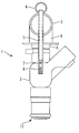
- a fuel injection valve 2 in the form of a low-pressure fuel injection valve is for injecting fuel into the intake pipe of a mixture-compression, spark-ignited internal combustion engine suitable.
- the fuel injection valve 2 is preferably installed in a series arrangement on a cylinder head, not shown, of the internal combustion engine and connected by means of a first fuel distributor line 3 with further fuel injection valves 2, not shown.
- the measures according to the invention relate to a second fuel distributor line 4, which may be arranged in particular parallel to the first fuel distributor line 3.
- the second fuel distribution line 4 serves to supply a starting fuel, which is designed in its properties with respect to evaporation and combustion so that the cold start properties improved, the hydrocarbon emissions in the cold running phase of the engine and the nitrogen oxide emissions can be reduced.
- the starting fuel may alternatively be replaced by a cleaning or rinsing liquid for cleaning the fuel injection valve 2 between the injection cycles. Deposits in the region of the fuel channels and the injection openings of the fuel injection valve 2 are thereby washed away and can no longer lead to malfunction of the fuel injection valve 2.
- the conception is chosen so that existing fuel injectors 2 without expensive modifications for use with the inventive measures are used, whereby the cost can be kept low.
- the second fuel distributor line 4 has a preferably tubular lance 5, which extends through the first fuel distributor line 3.
- the lance 5 opens into a supply pipe 6 of the fuel injection valve 2 in this one.
- a check valve 7 is arranged, which may be formed, for example, as a ball valve 7 with a spring 8.
- the check valve 7 ensures that the injection is terminated with starting fuel as soon as normal fuel is supplied via a feed line 9 from the first fuel distributor line 3. It is interchangeable and can be selected for any pressures, for example between 0.2 and 1 bar. A detailed description of the individual components and the mode of operation can be taken from the description of FIGS. 2A to 2C.
- the lance 5 and the second fuel distributor line 4 are preferably soldered to the first fuel distributor line 3.
- the diameter of the lance 5 is for example 4 mm in order to provide a sufficient Zumeßquerrough.
- the lance 5 can also be designed to be heated in order to heat the fuel.
- an improvement of the cold start properties can also be achieved by a better evaporation and a reduction of the hydrocarbons.
- the heating elements can be embodied in various forms such as spirals or in the form of heating pills.
- a tube may be provided in connection with an outer wall of the fuel injection valve 2, through which the starting fuel to the tip of the fuel injection valve 2 can be passed.
- a further advantageous embodiment combines the use of the lance 5 with the switching between starting and normal fuel through the use of two valves, whereby the fuel circuits can be completely decoupled from each other.
- the backwashing can be done via external channels.
- the fuel types are not subject to any restrictions with regard to the feed cross sections and the maximum possible flow rate.
- FIGS. 2A to 2C show a rinsing and injection cycle for a fuel injection system 1 configured in accordance with the invention in three steps.
- the fuel injection system 1 is shown in each case in a lateral, partially cutaway in the region of the fuel injection valve 2. Only the parts of a fuel injection valve 2 essential to the invention are referred to. Incidentally, the fuel injection valve 2 may be arbitrary. Identical components are provided in all figures with matching reference numerals.
- FIG. 2A shows the rinsing process as the first step of the injection cycle.
- starting fuel is passed through an interior 10 of the fuel injection valve 2 from the second fuel distributor line 4. Since no electrical actuation of the fuel injection valve 2 takes place at this time, the starting fuel is not injected, but flows through lateral channels 11, as indicated by the arrows 12, against a Abspritzraum back to the supply pipe 6 of the fuel injection valve 2.
- the check valve 7 prevents the backflow of the starting fuel into the second fuel distribution line 4.
- the aim of the flushing process is to obtain the combustion residues from the previous injection cycle in the range To solve the valve tip 13 and rinse so that the fuel injector 2 can inject consistent amounts of fuel into the combustion chamber of the internal combustion engine.
- Fig. 2B the next step, the injection of starting fuel in the direction of a combustion chamber of the internal combustion engine, is shown.
- the starting fuel is in this case supplied in the same manner as in the rinsing process shown in Fig. 2A, but is hosed by the simultaneous electrical actuation of the fuel injection valve 2 to the combustion chamber of the internal combustion engine. This is indicated by the arrows 14 in Fig. 2B.
- the starting fuel is adjusted so that, as already explained above, the cold start behavior of the internal combustion engine positively influenced and the exhaust emissions can be reduced.
- FIG. 2C shows the third step of the injection cycle in which normal fuel from the first fuel distributor line 3 is conducted via the inlet 9 and the lateral channels 10 to the valve tip 13 and is sprayed off to the combustion chamber of the internal combustion engine.
- the normal fuel flows through the fuel injection valve 2 along the path indicated by the arrows 15 and 14. Normal fuel is sprayed as soon as the internal combustion engine has reached its operating temperature, which can be measured by a suitable sensor.
- the normal fuel can be, for example, a fuel with higher energy density, which manages without the addition of cleaning agents.
- the invention is not limited to the illustrated embodiment and, for example, also suitable for fuel injection systems 1 of mixture-compressing, self-igniting internal combustion engines.
Landscapes
- Engineering & Computer Science (AREA)
- Chemical & Material Sciences (AREA)
- Combustion & Propulsion (AREA)
- Mechanical Engineering (AREA)
- General Engineering & Computer Science (AREA)
- Physics & Mathematics (AREA)
- Electromagnetism (AREA)
- Fuel-Injection Apparatus (AREA)
Description
- Die Erfindung geht aus von einer Brennstoffeinspritzanlage zum Einspritzen von Brennstoff in eine Brennkraftmaschine nach der Gattung des Anspruchs 1 und von einem Verfahren zum Einspritzen von Brennstoff gemäß Anspruch 10 (
GB-A-1150 043 - Eine Brennstoffeinspritzanlage nach dem Oberbegriff des Anspruchs 1 ist beispielsweise aus der
DE 101 23 867 A1 bekannt. Dabei umfaßt das Brennstoffeinspritzventil einen Hilfszulauf, welcher über eine Leitung mit einem Innenraum des Brennstoffeinspritzventils in Verbindung steht. Ein Reinigungsmittel oder ein Gemisch aus Brennstoff und Reinigungsmittel kann den Abspritzöffnungen des Brennstoffeinspritzventils über den Hilfszulauf zugeführt werden. Das Reinigungsmittel kann dabei zum Spülen des Brennstoffeinspritzventils und der Abspritzöffnungen zur Verminderung von Ablagerungen verwendet werden. - Nachteilig an der in der obengenannten Druckschrift beschriebenen Anordnung ist insbesondere, daß jedes der Brennstoffeinspritzventile einer Brennkraftmaschine mit einem entsprechenden Zulauf versehen werden muß, welcher zudem dezentral vom Brennstoffzulauf der Brennstoffeinspritzventile angeordnet ist. Der Herstellungsaufwand ist somit sehr hoch. Zudem muß eine zweite Zuleitung, welche die Hilfszuläufe miteinander verbindet, verlegt werden, was zusätzlichen Aufwand an Bauteilen und Montagezeit kostet.
- Die erfindungsgemäße Brennstoffeinspritzanlage mit den kennzeichnenden Merkmalen des Anspruchs 1 und das erfindungsgemäße Verfahren mit den kennzeichnenden Merkmalen des Anspruchs 10 haben demgegenüber den Vorteil, daß über zwei Brennstoffverteilerleitungen, welche über einen konventionellen Anschluß und über eine darin angeordnete Lanze mit den Brennstoffeinspritzventilen in Verbindung stehen, verschiedene Brennstoffe für verschiedene Betriebszustände der Brennkraftmaschine auf einfache Weise zuleitbar sind.
- Durch die in den Unteransprüchen aufgeführten Maßnahmen sind vorteilhafte Weiterbildungen und Verbesserungen der im Anspruch 1 angegebenen Brennstoffeinspritzanlage möglich.
- Von Vorteil ist dabei insbesondere, daß die zweite Brennstoffverteilerleitung parallel zu der ersten verläuft und mit dieser beispielsweise verlötet ist.
- Weiterhin ist von Vorteil, daß serienmäßige Brennstoffeinspritzventile ohne kostspielige Modifikationen mit der doppelten Brennstoffverteilerleitung verwendbar sind.
- Vorteilhafterweise ist in der Lanze ein Rückschlagventil vorgesehen, welches für einen beliebigen Druck frei wählbar ist und ein Rückströmen des Startbrennstoffs oder der Reinigungsflüssigkeit verhindert.
- Zudem ist vorteilhaft, daß die Zuleitung des Startbrennstoffs auch über eine äußere Hülse außen am Brennstoffeinspritzventil oder durch eine von der Hauptzuleitung entkoppelte weitere Zuleitung erfolgen kann.
- Weiterhin ist vorteilhaft, daß die Lanze die ersten Brennstoffverteilerleitung durchgreift, wodurch eine zusätzliche Evaporation des die Lanze durchströmenden Brennstoffs vermieden werden kann.
- Der Startbrennstoff kann vorteilhafterweise so zusammengesetzt sein, daß die Kaltstarteigenschaften der Brennkraftmaschine verbessert, die Schadstoffemission verringert und das Brennstoffeinspritzventil frei von Ablagerungen gehalten werden kann.
- Ein Ausführungsbeispiel der Erfindung ist in der Zeichnung vereinfacht dargestellt und in der nachfolgenden Beschreibung näher erläutert. Es zeigen:
- Fig. 1
- einen schematischen Schnitt durch ein Ausführungsbeispiel einer erfindungsgemäßen Brennstoffeinspritzanlage in einer Gesamtdarstellung,
- Fig. 2A-C
- seitliche Ansichten durch ein teilgeschnittenes Brennstoffeinspritzventil der in Fig. 1 dargestellten Brennstoffeinspritzanlage in drei aufeinanderfolgenden Verfahrensschritten der Einspritzung.
- Fig. 1 zeigt in einer schematischen Ansicht ein Ausführungsbeispiel einer erfindungsgemäß ausgestalteten Brennstoffeinspritzanlage 1. Ein Brennstoffeinspritzventil 2 in Form eines Niederdruck-Brennstoffeinspritzventils ist zum Einspritzen von Brennstoff in das Ansaugrohr einer gemischverdichtenden, fremdgezündeten Brennkraftmaschine geeignet. Es werden im Folgenden nur diejenigen Bauteile erläutert, die in direktem Zusammenhang mit den erfindungsgemäßen Maßnahmen stehen.
- Das Brennstoffeinspritzventil 2 ist vorzugsweise in einer Reihenanordnung an einem nicht weiter dargestellten Zylinderkopf der Brennkraftmaschine eingebaut und mittels einer ersten Brennstoffverteilerleitung 3 mit weiteren, nicht dargestellten Brennstoffeinspritzventilen 2 verbunden. Die erfindungsgemäßen Maßnahmen beziehen sich auf eine zweite Brennstoffverteilerleitung 4, welche insbesondere parallel zu der ersten Brennstoffverteilerleitung 3 angeordnet sein kann.
- Die zweite Brennstoffverteilerleitung 4 dient dabei der Zufuhr eines Startbrennstoffes, welcher in seinen Eigenschaften bezüglich Verdampfung und Verbrennung so konzipiert ist, daß die Kaltstarteigenschaften verbessert, der Kohlenwasserstoffausstoß in der Kaltlaufphase der Brennkraftmaschine sowie die Stickoxydemission reduziert werden können. Der Startbrennstoff kann alternativ auch durch eine Reinigungs- oder Spülflüssigkeit zur Reinigung des Brennstoffeinspritzventils 2 zwischen den Einspritzzyklen ersetzt werden. Ablagerungen im Bereich der Brennstoffkanäle und der Abspritzöffnungen des Brennstoffeinspritzventils 2 werden dadurch weggespült und können nicht mehr zu Fehlfunktionen des Brennstoffeinspritzventils 2 führen.
- Die Konzeptionierung ist dabei so gewählt, daß vorhandene Brennstoffeinspritzventile 2 ohne teure Modifikationen zur Anwendung mit den erfindungsgemäßen Maßnahmen verwendbar sind, wodurch die Kosten niedrig gehalten werden können.
- Die zweite Brennstoffverteilerleitung 4 weist zu diesem Zweck eine vorzugsweise rohrförmige Lanze 5 auf, welche sich durch die erste Brennstoffverteilerleitung 3 erstreckt. Die Lanze 5 mündet in einem Zuleitungsstutzen 6 des Brennstoffeinspritzventils 2 in dieses ein.
- In der Lanze 5 ist ein Rückschlagventil 7 angeordnet, welches beispielsweise als Kugelventil 7 mit einer Feder 8 ausgebildet sein kann. Das Rückschlagventil 7 sorgt dafür, daß die Einspritzung mit Startbrennstoff beendet wird, sobald normaler Brennstoff über eine Zuleitung 9 aus der ersten Brennstoffverteilerleitung 3 zugeführt wird. Es ist auswechselbar und kann für beliebige Drücke beispielsweise zwischen 0,2 und 1 bar ausgewählt werden. Eine genaue Beschreibung der einzelnen Bauteile und der Funktionsweise ist der Beschreibung zu den Fig. 2A bis 2C zu entnehmen.
- Die Lanze 5 und die zweite Brennstoffverteilerleitung 4 sind vorzugsweise mit der ersten Brennstoffverteilerleitung 3 verlötet. Der Durchmesser der Lanze 5 beträgt beispielsweise 4 mm, um einen ausreichenden Zumeßquerschnitt zu bieten.
- Durch die Durchführung der Lanze 5 durch die erste Brennstoffverteilerleitung 3 kann eine Zusatzevaporation des Startbrennstoffs vermieden werden.
- Weiterhin kann die Lanze 5 auch beheizbar ausgeführt sein, um den Brennstoff zu erwärmen. Damit kann ebenfalls eine Verbesserung der Kaltstarteigenschaften durch eine bessere Verdampfung und eine Reduktion der Kohlenwasserstoffe erzielt werden. Die Heizelemente können dabei in verschiedenen Formen wie Spiralen oder in Form von Heizpillen ausgeführt sein.
- Anstelle der Lanze 5 kann auch ein Rohr in Verbindung mit einer Außenwand des Brennstoffeinspritzventils 2 vorgesehen sein, durch welches der Startbrennstoff zur Spitze des Brennstoffeinspritzventils 2 geleitet werden kann. Vorteil dabei ist, daß sich die Umschaltstelle zwischen Startbrennstoff und Normalbrennstoff im Bereich der Ventilspitze befindet und dort nach dem Umschalten nur ein geringes Restvolumen der anderen Brennstoffsorte vorliegt, wodurch sich die Startemissionen verbessern. Auch hier sind serienmäßig gefertigte Brennstoffeinspritzventile 2 mit geringfügigen Modifikationen verwendbar.
- Eine weitere vorteilhafte Ausgestaltung verbindet die Verwendung der Lanze 5 mit der Umschaltung zwischen Start-und Normalbrennstoff durch die Verwendung von zwei Ventilen, wodurch die Brennstoffkreisläufe vollständig voneinander entkoppelt werden können. Die Rückspülung kann über äußere Kanäle erfolgen. Die Brennstoffsorten unterliegen hierbei keinerlei Einschränkungen hinsichtlich der Zuführungsquerschnitte und der maximal möglichen Durchflußmenge.
- Fig. 2A bis 2C zeigen einen Spül- und Einspritzzyklus für eine erfindungsgemäß ausgestaltete Brennstoffeinspritzanlage 1 in drei Schritten. Die Brennstoffeinspritzanlage 1 ist dabei jeweils in einer seitlichen, im Bereich des Brennstoffeinspritzventils 2 teilgeschnittenen Ansicht dargestellt. Es wird nur auf die für die Erfindung wesentlichen Teile eines Brennstoffeinspritzventils 2 Bezug genommen. Im übrigen kann das Brennstoffeinspritzventil 2 beliebig ausgeführt sein. Gleiche Bauteile sind dabei in allen Figuren mit übereinstimmenden Bezugszeichen versehen.
- Fig. 2A zeigt als ersten Schritt des Einspritzzyklus den Spülvorgang. Hierbei wird aus der zweiten Brennstoffverteilerleitung 4 Startbrennstoff durch einen Innenraum 10 des Brennstoffeinspritzventils 2 geleitet. Da zu diesem Zeitpunkt keine elektrische Betätigung des Brennstoffeinspritzventils 2 erfolgt, wird der Startbrennstoff nicht eingespritzt, sondern fließt durch seitliche Kanäle 11, wie durch die Pfeile 12 angedeutet, entgegen einer Abspritzrichtung zurück zum Zuleitungsstutzen 6 des Brennstoffeinspritzventils 2. Das Rückschlagventil 7 verhindert dabei das Zurückströmen des Startbrennstoffs in die zweite Brennstoffverteilerleitung 4.
- Ziel des Spülvorgangs ist es, die vom vorhergehenden Einspritzzyklus stammenden Verbrennungsrückstände im Bereich der Ventilspitze 13 zu lösen und auszuspülen, damit das Brennstoffeinspritzventil 2 gleichbleibende Brennstoffmengen in den Brennraum der Brennkraftmaschine einspritzen kann.
- In Fig. 2B ist der nächste Schritt, das Einspritzen von Startbrennstoff in Richtung eines Brennraums der Brennkraftmaschine, dargestellt. Der Startbrennstoff wird hierbei in gleicher Weise zugeleitet wie bei dem in Fig. 2A dargestellten Spülvorgang, wird jedoch durch die gleichzeitige elektrische Betätigung des Brennstoffeinspritzventils 2 zum Brennraum der Brennkraftmaschine hin abgespritzt. Dies ist durch die Pfeile 14 in Fig. 2B angedeutet. Der Startbrennstoff ist dabei so abgestimmt, daß, wie weiter oben bereits erläutert, das Kaltstartverhalten der Brennkraftmaschine positiv beeinflußt und die Abgasemissionen vermindert werden können.
- Fig. 2C zeigt schließlich den dritten Schritt des Einspritzzyklus, bei welchem Normalbrennstoff aus der ersten Brennstoffverteilerleitung 3 über den Zulauf 9 und die seitlichen Kanäle 10 zur Ventilspitze 13 geleitet und zum Brennraum der Brennkraftmaschine hin abgespritzt wird. Der Normalbrennstoff durchfließt dabei das Brennstoffeinspritzventil 2 entlang des durch die Pfeile 15 und 14 gekennzeichneten Wegs. Normalbrennstoff wird abgespritzt, sobald die Brennkraftmaschine ihre Betriebstemperatur erreicht hat, was durch einen geeigneten Sensor gemessen werden kann. Der Normalbrennstoff kann dabei beispielsweise ein Brennstoff mit höherer Energiedichte sein, welcher dafür ohne den Zusatz von Reinigungsstoffen auskommt.
- Die Erfindung ist nicht auf das dargestellte Ausführungsbeispiel beschränkt und beispielsweise auch für Brennstoffeinspritzanlagen 1 von gemischverdichtenden, selbstzündenden Brennkraftmaschinen geeignet.
Claims (10)
- Brennstoffeinspritzanlage (1) zum Einspritzen von Brennstoff in eine Brennkraftmaschine mit zumindest einem Brennstoffeinspritzventil (2), mit einer ersten Brennstoffverteilerleitung (3), die mit jedem Brennstoffeinspritzventil (2) verbunden ist, und mit einer zweiten Brennstoffverteilerleitung (4), welche mit jedem der Brennstoffeinspritzventile (2) in Verbindung steht,
dadurch gekennzeichnet,
dass an der zweiten Brennstoffverteilerleitung (4) Lanzen (5) zur Verbindung mit den Brennstoffeinspritzventilen (2) vorgesehen sind und jede Lanze (5) die erste Brennstoffverteilerleitung (3) durchgreift. - Brennstoffeinspritzanlage nach Anspruch 1,
dadurch gekennzeichnet,
dass die zweite Brennstoffverteilerleitung (4) parallel zu der ersten Brennstoffverteilerleitung (3) angeordnet ist. - Brennstoffeinspritzanlage nach Anspruch 2,
dadurch gekennzeichnet,
dass die zweite Brennstoffverteilerleitung (4) mit der ersten Brennstoffverteilerleitung (3) mittels Löten verbunden ist. - Brennstoffeinspritzanlage nach einem der Ansprüche 1 bis 3,
dadurch gekennzeichnet,
dass jede Lanze (5) mit der zweiten Brennstoffverteilerleitung (4) mittels Löten verbunden ist. - Brennstoffeinspritzanlage nach einem der Ansprüche 1 bis 4,
dadurch gekennzeichnet,
dass sich jede Lanze (5) in einen Zuleitungsstutzen (6) des Brennstoffeinspritzventils (2) erstreckt. - Brennstoffeinspritzanlage nach einem der Ansprüche 1 bis 5,
dadurch gekennzeichnet,
dass die Lanze (5) einen Durchmesser von ca. 4 mm aufweist. - Brennstoffeinspritzanlage nach einem der Ansprüche 1 bis 6,
dadurch gekennzeichnet,
dass in der Lanze (5) ein Rückschlagventil (7) angeordnet ist. - Brennstoffeinspritzanlage nach Anspruch 7,
dadurch gekennzeichnet,
dass das Rückschlagventil (7) als Kugelventil (7) mit einer Feder (8) ausgebildet ist. - Brennstoffeinspritzanlage nach einem der Ansprüche 1 bis 8,
dadurch gekennzeichnet,
dass das Brennstoffeinspritzventil (2) über einen Zulauf (9) mit der ersten Brennstoffverteilerleitung (3) in Verbindung steht. - Verfahren zum Einspritzen von Brennstoff mittels einer Brennstoffeinspritzanlage (1) in eine Brennkraftmaschine mit zumindest einem Brennstoffeinspritzventil (2) und einer ersten Brennstoffverteilerleitung (3), die mit jedem Brennstoffeinspritzventil (2) verbunden ist, und einer zweiten Brennstoffverteilerleitung (4), welche mit jedem der Brennstoffeinspritzventile (2) in Verbindung steht,
dadurch gekennzeichnet,
dass das Verfahren folgende Verfahrensschritte umfasst:- Zuleiten von Startbrennstoff über die zweite Brennstoffverteilerleitung (4) und eine an dieser vorgesehenen Lanze (5), die die erste Brennstoffventeilerleitung (3) durchgreift, in das Brennstoffeinspritzventil (2) und Spülen des Brennstoffeinspritzventils (2);- Zuleiten von Startbrennstoff über die zweite Brennstoffverteilerleitung (4) und die Lanze (5) in das Brennstoffeinspritzventil (2) und gleichzeitiges Betätigen des Brennstoffeinspritzventils (2) zum Einspritzen des Startbrennstoffs in den Brennraum der Brennkraftmaschine;- Wiederholen der ersten beiden Verfahrensschritte bis zum Erreichen der Betriebstemperatur der Brennkraftmaschine; und- Zuleiten von Normalbrennstoff über die erste Brennstoffverteilerleitung (3) und einen Zulauf (9) in das Brennstoffeinspritzventil (2) und gleichzeitiges Betätigen des Brennstoffeinspritzventils (2) zum Einspritzen des Normalbrennstoffs in den Brennraum der Brennkraftmaschine.
Applications Claiming Priority (2)
| Application Number | Priority Date | Filing Date | Title |
|---|---|---|---|
| DE10337893A DE10337893A1 (de) | 2003-08-18 | 2003-08-18 | Brennstoffeinspritzanlage und Verfahren zum Einspritzen von Brennstoff |
| PCT/EP2004/051818 WO2005019636A1 (de) | 2003-08-18 | 2004-08-18 | Brennstoffeinspritzanlage und verfahren zum einspritzen von brennstoff |
Publications (2)
| Publication Number | Publication Date |
|---|---|
| EP1658425A1 EP1658425A1 (de) | 2006-05-24 |
| EP1658425B1 true EP1658425B1 (de) | 2008-01-16 |
Family
ID=34201627
Family Applications (1)
| Application Number | Title | Priority Date | Filing Date |
|---|---|---|---|
| EP04766519A Expired - Lifetime EP1658425B1 (de) | 2003-08-18 | 2004-08-18 | Brennstoffeinspritzanlage und verfahren zum einspritzen von brennstoff |
Country Status (5)
| Country | Link |
|---|---|
| US (1) | US7523740B2 (de) |
| EP (1) | EP1658425B1 (de) |
| JP (1) | JP4550819B2 (de) |
| DE (2) | DE10337893A1 (de) |
| WO (1) | WO2005019636A1 (de) |
Families Citing this family (8)
| Publication number | Priority date | Publication date | Assignee | Title |
|---|---|---|---|---|
| US7861696B2 (en) * | 2005-11-26 | 2011-01-04 | Exen Holdings, Llc | Multi fuel co-injection system for internal combustion and turbine engines |
| US8333171B2 (en) * | 2009-02-06 | 2012-12-18 | Exen Holdings, Llc | Homogenizing fuel enhancement system |
| BRPI1005341B1 (pt) | 2010-12-02 | 2016-12-20 | Bosch Do Brasil | galeria de combustível de material plástico com sistema de aquecimento |
| US8596561B2 (en) | 2011-08-31 | 2013-12-03 | Caterpillar Inc. | Dual fuel injector with hydraulic lock seal |
| JP6254403B2 (ja) * | 2013-09-20 | 2017-12-27 | 株式会社デンソー | 燃料加熱システム、および、これを用いた燃料レール |
| JP6274799B2 (ja) * | 2013-09-20 | 2018-02-07 | 株式会社デンソー | 燃料加熱システム、および、これを用いた燃料レール |
| WO2017031598A1 (en) * | 2015-08-27 | 2017-03-02 | Westport Power Inc. | Deposit mitigation for gaseous fuel injectors |
| US9771887B2 (en) * | 2015-11-23 | 2017-09-26 | Ford Global Technologies, Llc | Single rail combined fuel injection |
Family Cites Families (16)
| Publication number | Priority date | Publication date | Assignee | Title |
|---|---|---|---|---|
| NL36160C (de) * | 1933-05-22 | |||
| DE849325C (de) * | 1940-09-19 | 1952-09-15 | Bosch Gmbh Robert | Einspritzventil fuer Brennkraftmaschinen |
| DE969853C (de) * | 1952-12-25 | 1958-07-24 | Maschf Augsburg Nuernberg Ag | Einrichtung zur Verwendung verschiedener Brennstoffarten und -mengen bei Einspritzduesen von Brennkraftmaschinen |
| GB1150043A (en) * | 1967-03-13 | 1969-04-30 | Caterpillar Tractor Co | A Compression Ignition Engine Fuel System |
| DE3243176A1 (de) * | 1982-11-23 | 1984-05-24 | Deutsche Forschungs- und Versuchsanstalt für Luft- und Raumfahrt e.V., 5000 Köln | Einspritzeinrichtung fuer alkoholkraftstoffe, insbesondere bei direkteinspritzenden dieselmotoren |
| JPH0323656U (de) * | 1989-07-18 | 1991-03-12 | ||
| DE69600267T2 (de) * | 1996-02-16 | 1998-08-27 | Fiat Ricerche | Brennkraftmaschine mit Methaneinspritzsystem |
| JP3778385B2 (ja) * | 1996-10-03 | 2006-05-24 | 臼井国際産業株式会社 | コモンレール |
| US5887799A (en) * | 1997-09-11 | 1999-03-30 | Impco Technoligies, Inc. | Dual fuel injector |
| DE19746491A1 (de) * | 1997-10-22 | 1999-04-29 | Bosch Gmbh Robert | Kraftstoffeinspritzanlage für eine Brennkraftmaschine |
| US6604510B2 (en) * | 2000-10-04 | 2003-08-12 | Siemens Automotive Corporation | Fuel system including a fuel injector directly mounted to a fuel rail |
| DE10123867A1 (de) | 2001-05-16 | 2002-11-28 | Bosch Gmbh Robert | Brennstoffeinspritzventil |
| JP2003056425A (ja) * | 2001-08-21 | 2003-02-26 | Aisan Ind Co Ltd | 内燃機関の燃料噴射装置 |
| US6886537B2 (en) * | 2002-07-04 | 2005-05-03 | Denso Corporation | Accumulation type fuel injection system for engine |
| US7077101B2 (en) * | 2002-08-14 | 2006-07-18 | Electro-Motive Diesel, Inc. | Hybrid fuel injection system |
| JP4021838B2 (ja) * | 2003-09-02 | 2007-12-12 | 株式会社日立製作所 | 燃料噴射装置 |
-
2003
- 2003-08-18 DE DE10337893A patent/DE10337893A1/de not_active Withdrawn
-
2004
- 2004-08-18 WO PCT/EP2004/051818 patent/WO2005019636A1/de not_active Ceased
- 2004-08-18 JP JP2006523634A patent/JP4550819B2/ja not_active Expired - Fee Related
- 2004-08-18 DE DE502004005973T patent/DE502004005973D1/de not_active Expired - Lifetime
- 2004-08-18 EP EP04766519A patent/EP1658425B1/de not_active Expired - Lifetime
- 2004-08-18 US US10/566,862 patent/US7523740B2/en not_active Expired - Fee Related
Also Published As
| Publication number | Publication date |
|---|---|
| JP4550819B2 (ja) | 2010-09-22 |
| DE502004005973D1 (de) | 2008-03-06 |
| WO2005019636A1 (de) | 2005-03-03 |
| DE10337893A1 (de) | 2005-03-17 |
| EP1658425A1 (de) | 2006-05-24 |
| JP2007502930A (ja) | 2007-02-15 |
| US20070169749A1 (en) | 2007-07-26 |
| US7523740B2 (en) | 2009-04-28 |
Similar Documents
| Publication | Publication Date | Title |
|---|---|---|
| EP1658428B1 (de) | Brennstoffeinspritzventil | |
| EP1364115B1 (de) | Brennstoffeinspritzventil | |
| DE112021002882T5 (de) | Brennkraftmaschine mit mehreren kraftstoffeinspritzungen ausserhalb einer vorkammer | |
| DE10122256A1 (de) | Kraftstoff-Einspritzvorrichtung für Brennkraftmaschinen, insbesondere Common-Rail-Injektor, sowie Kraftstoffsystem und Brennkraftmaschine | |
| DE102020208768A1 (de) | Brennstoffverteilerleiste für eine Einspritzanlage und Einspritzanlage für gemischverdichtende, fremdgezündete Brennkraftmaschinen | |
| DE10337893A1 (de) | Brennstoffeinspritzanlage und Verfahren zum Einspritzen von Brennstoff | |
| DE10007175C2 (de) | Einspritzventil für die Einspritzung von Kraftstoff in eine Verbrennungskraftmaschine | |
| DE602004003896T2 (de) | Flüssigkeitseinspritzventil und sein Herstellungverfahren | |
| DE10247958A1 (de) | Kraftstoff-Einspritzvorrichtung für eine Brennkraftmaschine | |
| DE10259799A1 (de) | Brennstoffeinspritzventil | |
| DE10307873A1 (de) | Sackloch- und Sitzloch-Einspritzdüse für eine Brennkraftmaschine mit einem Übergangskegel zwischen Sackloch und Düsennadelsitz | |
| EP1576279B1 (de) | Brennstoffeinspritzventil | |
| EP1606508A1 (de) | Brennstoffeinspritzventil | |
| EP3168454B1 (de) | Ventil zum Zumessen eines Fluids und Anordnung mit solch einem Ventil | |
| DE10008445B4 (de) | Kraftstoffeinspritzdüse für eine direkt einspritzende Brennkraftmaschine | |
| EP1442210B1 (de) | Brennstoffeinspritzventil | |
| WO2006128773A1 (de) | Kraftstoffeinspritzdüse | |
| DE102008044243A1 (de) | Brennkraftmaschine | |
| EP1116877B1 (de) | Kraftstoffsystem einer Brennkraftmaschine | |
| AT500011B1 (de) | Einspritzinjektor für brennkraftmaschinen | |
| EP4667731A1 (de) | Kraftstoffinjektor einer brennkraftmaschine und brennkraftmaschine | |
| DE102021208996A1 (de) | Fluidverteiler für eine Einspritzanlage und Einspritzanlage für gemischverdichtende, fremdgezündete Brennkraftmaschinen. | |
| EP1339979A1 (de) | Verfahren zum ausblasen von brennstoff aus einem volumen eines brenstoffeinspritzventils | |
| EP4345280A1 (de) | Einspritzdüse für einen dual-fuel-motor, dual-fuel-motor und verfahren zum betreiben desselben | |
| DE102019220392A1 (de) | Komponente, insbesondere Brennstoffleitung, Brennstoffverteiler oder Pumpe, und Brennstoffeinspritzanlage |
Legal Events
| Date | Code | Title | Description |
|---|---|---|---|
| PUAI | Public reference made under article 153(3) epc to a published international application that has entered the european phase |
Free format text: ORIGINAL CODE: 0009012 |
|
| 17P | Request for examination filed |
Effective date: 20060320 |
|
| AK | Designated contracting states |
Kind code of ref document: A1 Designated state(s): DE FR GB IT |
|
| DAX | Request for extension of the european patent (deleted) | ||
| RBV | Designated contracting states (corrected) |
Designated state(s): DE FR GB IT |
|
| 17Q | First examination report despatched |
Effective date: 20061129 |
|
| GRAP | Despatch of communication of intention to grant a patent |
Free format text: ORIGINAL CODE: EPIDOSNIGR1 |
|
| GRAS | Grant fee paid |
Free format text: ORIGINAL CODE: EPIDOSNIGR3 |
|
| GRAA | (expected) grant |
Free format text: ORIGINAL CODE: 0009210 |
|
| AK | Designated contracting states |
Kind code of ref document: B1 Designated state(s): DE FR GB IT |
|
| REG | Reference to a national code |
Ref country code: GB Ref legal event code: FG4D Free format text: NOT ENGLISH |
|
| REF | Corresponds to: |
Ref document number: 502004005973 Country of ref document: DE Date of ref document: 20080306 Kind code of ref document: P |
|
| GBT | Gb: translation of ep patent filed (gb section 77(6)(a)/1977) |
Effective date: 20080417 |
|
| ET | Fr: translation filed | ||
| PLBE | No opposition filed within time limit |
Free format text: ORIGINAL CODE: 0009261 |
|
| STAA | Information on the status of an ep patent application or granted ep patent |
Free format text: STATUS: NO OPPOSITION FILED WITHIN TIME LIMIT |
|
| 26N | No opposition filed |
Effective date: 20081017 |
|
| PGFP | Annual fee paid to national office [announced via postgrant information from national office to epo] |
Ref country code: FR Payment date: 20100901 Year of fee payment: 7 Ref country code: IT Payment date: 20100826 Year of fee payment: 7 |
|
| PGFP | Annual fee paid to national office [announced via postgrant information from national office to epo] |
Ref country code: GB Payment date: 20100823 Year of fee payment: 7 |
|
| GBPC | Gb: european patent ceased through non-payment of renewal fee |
Effective date: 20110818 |
|
| REG | Reference to a national code |
Ref country code: FR Ref legal event code: ST Effective date: 20120430 |
|
| PG25 | Lapsed in a contracting state [announced via postgrant information from national office to epo] |
Ref country code: IT Free format text: LAPSE BECAUSE OF NON-PAYMENT OF DUE FEES Effective date: 20110818 |
|
| PG25 | Lapsed in a contracting state [announced via postgrant information from national office to epo] |
Ref country code: FR Free format text: LAPSE BECAUSE OF NON-PAYMENT OF DUE FEES Effective date: 20110831 Ref country code: GB Free format text: LAPSE BECAUSE OF NON-PAYMENT OF DUE FEES Effective date: 20110818 |
|
| PGFP | Annual fee paid to national office [announced via postgrant information from national office to epo] |
Ref country code: DE Payment date: 20161027 Year of fee payment: 13 |
|
| REG | Reference to a national code |
Ref country code: DE Ref legal event code: R119 Ref document number: 502004005973 Country of ref document: DE |
|
| PG25 | Lapsed in a contracting state [announced via postgrant information from national office to epo] |
Ref country code: DE Free format text: LAPSE BECAUSE OF NON-PAYMENT OF DUE FEES Effective date: 20180301 |