EP1655818A1 - Nutisolierung und Mehrfach-Resolver mit einer solchen Nutisolierung - Google Patents
Nutisolierung und Mehrfach-Resolver mit einer solchen Nutisolierung Download PDFInfo
- Publication number
- EP1655818A1 EP1655818A1 EP05020607A EP05020607A EP1655818A1 EP 1655818 A1 EP1655818 A1 EP 1655818A1 EP 05020607 A EP05020607 A EP 05020607A EP 05020607 A EP05020607 A EP 05020607A EP 1655818 A1 EP1655818 A1 EP 1655818A1
- Authority
- EP
- European Patent Office
- Prior art keywords
- winding
- annular plate
- pair
- insulated winding
- slot
- Prior art date
- Legal status (The legal status is an assumption and is not a legal conclusion. Google has not performed a legal analysis and makes no representation as to the accuracy of the status listed.)
- Withdrawn
Links
- 239000012212 insulator Substances 0.000 title claims abstract description 134
- 238000004804 winding Methods 0.000 claims abstract description 204
- 238000003780 insertion Methods 0.000 claims abstract description 38
- 230000037431 insertion Effects 0.000 claims abstract description 38
- 239000011347 resin Substances 0.000 description 22
- 229920005989 resin Polymers 0.000 description 22
- 239000011248 coating agent Substances 0.000 description 9
- 238000000576 coating method Methods 0.000 description 9
- 238000000465 moulding Methods 0.000 description 6
- 239000000463 material Substances 0.000 description 5
- 230000000694 effects Effects 0.000 description 4
- 238000002347 injection Methods 0.000 description 4
- 239000007924 injection Substances 0.000 description 4
- 238000004519 manufacturing process Methods 0.000 description 4
- 239000002184 metal Substances 0.000 description 4
- 238000001746 injection moulding Methods 0.000 description 2
- 238000009413 insulation Methods 0.000 description 2
- 238000000034 method Methods 0.000 description 2
- 238000005452 bending Methods 0.000 description 1
- 230000002950 deficient Effects 0.000 description 1
- 238000001035 drying Methods 0.000 description 1
- 239000000203 mixture Substances 0.000 description 1
- 230000002265 prevention Effects 0.000 description 1
Images


Classifications
-
- H—ELECTRICITY
- H02—GENERATION; CONVERSION OR DISTRIBUTION OF ELECTRIC POWER
- H02K—DYNAMO-ELECTRIC MACHINES
- H02K3/00—Details of windings
- H02K3/32—Windings characterised by the shape, form or construction of the insulation
- H02K3/34—Windings characterised by the shape, form or construction of the insulation between conductors or between conductor and core, e.g. slot insulation
- H02K3/345—Windings characterised by the shape, form or construction of the insulation between conductors or between conductor and core, e.g. slot insulation between conductor and core, e.g. slot insulation
Definitions
- the present invention relates to a multiplexed resolver in which plural resolver units are fitted in a single case so that they integrally operate, and particularly to a slot insulator provided in an assembly in which all stator yokes of a multiplexed resolver are assembled.
- One resolver unit means a structure constituting one resolver in a multiplexed resolver.
- the resolver unit has a function to detect a rotation angle, a rotation angle position and the like similarly to a resolver in the related art, and the resolver units are mainly stacked and coupled.
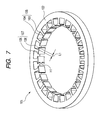
- Fig. 7 is a perspective view of a general stator yoke in one type of resolver.
- a stator yoke 101 includes an outside cylindrical part 102, a winding part 103 facing toward the center from the cylindrical part 102, and a winding holding part 104 provided in a protruding condition at the tip of the winding part 103.
- a combination of the winding part 103 and the winding holding part 104 is called a tooth 105.
- the winding holding part 104 is formed into a rectangular parallelpiped having a quadrate inward surface.
- the width of a protrusion 107 of a residual obtained by subtracting the width of the winding part 103 from the width of the winding holding part 104 in the circumferential direction is twice as large as a width L1 of a one-sided protrusion 106.
- the height of the stator yoke 101 in the center axis direction (direction of the center axis of the outside cylindrical part 102 of the stator yoke 101) is uniformly formed to be H1.
- the height of the one-sided protrusion 106 is also H1.
- a winding (not shown) with insulating coating is wound around the winding part 103 through an insulator (not shown).
- the illustration of a rotor is omitted.
- a resolver including one stator yoke 101 in which a number of teeth 105 are provided on one cylindrical part 102 and windings are wound around the teeth 105, and one rotor (not shown) is called a simplexed resolver.
- a multiplexed resolver, for example, an M-plexed resolver is such that basically, the resolver of Fig. 7 is made one resolver unit and M such resolver units are assembled and fixed.
- a slot insulator is used as an insulator provided on the winding part 103.
- a pair of slot insulators are mounted (attached) to the stator yoke 101 of Fig. 7 so as to cover the stator yoke 101 from above and below in a direction along the center axis of the stator yoke 101 (see, for example, JP-A-2001-95188, JP-A-2001-169493 and JP-A-2002-171737).
- the slot insulator plays an important role at the time of mass production.
- a multiplexed (M-plexed) resolver in which plural (arbitrary M) resolver units are stacked into an integral assembly is known.
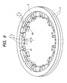
- Fig. 8 is a perspective view of a stator yoke in a duplexed resolver.
- a stator yoke 1 of the duplexed resolver of Fig. 8 is the stator yoke of the duplexed resolver in which a structure of a simplexed resolver is made one resolver unit, and two such resolver units are stacked to form an integral assembly.
- Winding parts 3 are provided on each of the upper and lower stator yokes 1 to be shifted so that they are not overlapped with each other at a common angle position on the circumference.
- a winding holding part 4 and the winding part 3 constitute a tooth 5.
- the number of the teeth 5 and the interval are suitably set in relation to an axial double angle or the like.
- the arrangement of the respective teeth 5 in the circumferential direction is the arrangement in the order corresponding to the order of the resolver units, that is, the stator yokes.
- An interval of a height H3 equivalent to the thickness of a cylindrical part 2 is produced between the winding parts 3 of the upper and lower stator yokes 1.
- the form of a triplexed or higher multiplexed resolver can be similarly constructed.
- Fig. 9 is a perspective view of a slot insulator (hereinafter referred to as an imaginary slot insulator) for an integral duplexed resolver, which was not realized.
- An imaginary slot insulator 301 is made of an insulating resin material, and includes an outside annular plate 302, insulated winding parts 303 facing toward the center from the annular plate 302, and insulated winding holding parts 304 provided in a protruding condition at the tips of the insulated winding parts 303.
- the insulated winding holding part 304 includes a pair of left and right shorter side parts 306 and a longer side part 305.
- the insulated winding holding parts 304 in each which a longer side part 305 and a shorter side part 306 are coupled, are provided to be sifted correspondingly to the respective teeth of two stator yokes provided to form upper and lower two stages and to be shifted in the direction along the center axis of the annular plate 302.
- the shorter side part 306 is a portion protruding from the outside surface of the winding part toward an adjacent tooth, that is, a portion having an area of a width L1 x height H2 in Fig. 9.
- the width L1 in the shorter side part 306 of Fig. 9 is the same as the width L1 of the one-sided protrusion 106 of the stator yoke 101 of Fig. 7.
- the height H2 in the shorter side part 306 of Fig. 9 is half of the height H1 of the one-sided protrusion of the stator yoke of Fig. 7.
- the total area of the pair of the shorter side parts 306 of the combined slot insulators 301 in the direction along center axis is made the same as the area of the one-sided protrusion of the stator yoke.
- the one-sided protrusion of the winding holding part of the stator yoke is supported from the backside by the pair of the shorter side parts 306 opposite to each other, and the winding holding part of the stator yoke can be positioned and covered by the pair of the longer side parts 305 opposite to each other.
- an insertion groove 307 opening downward and toward both sides in the radial direction is provided in the insulated winding part 303 of the slot insulator 301 shown in Fig. 9.
- An opening of the insertion groove 307 at the inward end of the radial direction is provided between the pair of shorter side parts.
- the insertion groove 307 is constructed so that half of the winding part of the stator yoke can be housed.
- the winding part of the stator yoke can be covered from both sides by the pair of the half insulated winding parts 303.
- the shorter side part 306 can be constructed such that when the winding (not shown) is wound around the insulated winding holding part 303, the winding does not come in direct contact with the winding holding part of the stator yoke without the slot insulator 301.
- the annular plate 302 is disposed to be in contact with the upper end surface and the lower end surface of the cylindrical part of the stator yoke assembly.
- the insulated winding parts 303 corresponding to the respective teeth of the first stage stator yoke are provided to protrude a direction toward a center of the annular plate 302, while the heights of the upper surfaces (upper surfaces when viewed in the center axis direction of the annular plate) are made uniform.
- extension plate parts 308 coupled at right angles (in the direction along the center axis) to the inside end of the annular plate 302, the insulated winding parts 303 corresponding to the respective teeth of the second stage stator yoke are similarly provided to protrude.
- the extension plate part 308 is made a shape obtained by cutting a part of a cylinder.
- a ring part 309 obtained by cutting a part of a ring, a crossover guide 310, and an engagement part 311 are provided on the annular plate 302.
- the ring part 309 stops the leakage of resin to the outside when a crossover (not shown) engaged with the crossover guide 310 is fixed by resin.
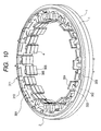
- Fig. 10 is an imaginary view in which the imaginary slot insulator of Fig. 9 is applied to the integral duplexed resolver of Fig. 8. Since reference numerals in Fig. 10 are the same as those explained in Figs. 8 and 9, their explanation will be omitted in Fig. 10.
- stator yoke 1 When the stator yoke 1 is covered with the imaginary slot insulators 301 from above and below in the direction along the center axis of the cylindrical part, what is shown in Fig. 10 is expected.
- the slot insulator of Fig. 9 is manufactured by, for example, injection molding of insulating resin. In that case, there arise problems as set forth below.
- An object of an illustrative, non-limiting embodiment of the invention is to provide a slot insulator for a multiplexed resolver.
- Another object of an illustrative, non-limiting embodiment of the invention is to provide a multiplexed resolver having a slot insulator that has a simple structure so that resin molding becomes easy.
- An illustrative, non-limiting embodiment of the invention is characterized in that a slot insulator of a multiplexed resolver, for example, an M-plexed resolver is not made to have a shape conforming to the arrangement position of teeth of an M-plexed stator yoke, but is made to have a shape corresponding to a simplexed resolver having the total slot number of M stator yokes.
- an insulated winding part of a slot insulator in which a winding part of a stator yoke is not housed and an insulated winding part of a slot insulator in which a winding part of a stator yoke is housed are coupled into one body and the winding is wound.
- Fig. 8 is a perspective view of a general stator yoke structure of a duplexed resolver.
- Each of stator yokes 1 includes an outside cylindrical part 2, winding parts 3 protruding toward the center from the cylindrical part 2, and winding holding parts 4 provided in a protruding condition at the tips of the winding parts 3.
- a combination of the winding part 3 and the winding holding part 4 is called a tooth 5.
- the winding holding part 4 is formed to be a plate-like body part having an arc surface.
- the width of a protrusion 7 of a residual obtained by subtracting the width of the winding part from the width of the winding holding part 4 in the circumferential direction is twice as large as a width L1 of a one-sided protrusion 6.
- the height of the stator yoke 1 in the center axis direction (the direction along the center axis of the cylindrical part 2) is uniformly formed to be a predetermined height H1.
- the height of the one-sided protrusion is also H1.
- stator yoke 1 of Fig. 8 an insulation coated wire (not shown) is wound around the winding part 3 through an insulator.
- the illustration of a rotor is omitted.
- a resolver including the stator yoke 1 in which a number of teeth 5 are provided in one cylindrical part 2 and a winding (not shown) is wound around each of the teeth 5 and a rotor (not shown) is called a simplexed resolver.
- a multiplexed resolver, for example, an M-plexed resolver is such that basically, the resolver of Fig. 8 is one resolver unit, and M such resolver units are combined into one body.
- a slot insulator is used as the insulator provided on the winding part 3.
- the slot insulator attached to the stator yoke 1 of Fig. 8 is constructed such that one of a pair of slot insulators is attached from above and the other of the pair is attached form below in the center axis direction.
- Fig. 1 is a perspective view of a slot insulator mounted to a stator yoke assembly of the duplexed resolver of Fig. 8.
- a slot insulator 10 is made of insulating resin material and includes an annular plate 11 having an outside annular plate, insulated winding part 12 protruding toward the center from the annular plate 11, and insulated winding holding parts 13 provided in a protruding condition at the tips of the insulated winding parts 12.
- the insulated winding holding part 13 includes a pair of left and right shorter side parts 14 and 14 and a longer side part 15.
- Each of the pair of shorter side parts 14 has a length in the center axis direction of the annular plate (i.e., the direction along the center axis of the annular plate), which is n times as large as the thickness of one stator yoke, where n is an arbitrary integer.
- An insertion groove 16 for housing the winding part 3 of the tooth 5 of the stator yoke 1 is provided in the insulated winding part 12.
- the insertion groove 16 is provided in the insulated winding part 12 so as to open in one direction along the center axis of the annular plate 11 and to open at both ends of the insertion groove 16 in the radial direction of the annular plate 11.
- the opening of the insertion groove 16 at an inward end in the radial direction is provided between the pair of shorter side parts 14 and 14.
- the pair of shorter side parts 14 and 14 along the circumferential surface is provided at both sides of the inward end of the insulated winding part 12 in the length direction (i.e., in the radial direction of the annular plate 11).
- the longer side part 15 is provided at the side opposite to the opening in the one direction along the center axis of the annular plate 11, the opening being provided at the inward end of the insulated winding part 12 in the radial direction of the annular plate 11.
- the pair of shorter side parts 14 and 14 and the longer side part 15 surround the opening of the insertion groove 16 on three sides at the inward end of the insulated winding part 12 in the radial direction of the annular part 11.
- the one shorter side part 14 corresponds to a portion, in the winding holding part of the stator yoke, protruding from the outside surface of the winding part to the adjacent tooth side, that is, the one-sided protrusion 6 having the area of the width L1 x height H1 in Fig. 8.
- a height H2 of the shorter side part 14 of Fig. 1 becomes the height H1 of the one-sided protrusion 6 of the stator yoke 1 of Fig. 8.
- the insertion groove 16 is constructed to be capable of housing the winding part of the tooth of the plural combined stator yokes.
- the winding holding part 4 of the stator yoke 1 the position of which is vertically changed in the center axis direction, can be positioned and be covered between the pair of longer side parts 15 and 15 vertically facing to each other.
- the winding part 3 of the stator yoke 1 can be housed in the insertion groove 16 of the pair of the insulated winding parts 12 and 12 vertically facing to each other. (See Fig. 2.)
- the pair of shorter side parts 14 and 14 and the longer side part 15 can be constructed such that when the winding is wound around the insulated winding part 12, the winding does not come in direct contact with the winding holding part directly without the slot insulator 10.
- the plate surface of the annular plate 11 is made the reference position, and all the insulated winding parts 12 are provided at the common height position. Besides, all the insulated winding holding parts 13 are provided at the common height position. By this, the flow of resin at the time of resin molding can be improved.
- the annular plates 11 are disposed to be in contact with the upper and lower surfaces of the cylindrical parts 2 of the stator yoke assembly.
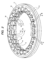
- Fig. 2 is an assembly perspective view in which a pair of the slot insulators shown in Fig. 1 is attached to the stator yoke assembly of the duplexed resolver from both sides.
- the winding part 3 of the stator yoke 1 is attached to the insertion groove 16 of the insulated winding part 12, and at the same time, the protrusion of the winding holding part 4 of the stator yoke 1 is brought into contact with the inward surface of the shorter side part 14, and the upper side of the winding holding part 4 is brought into contact with the lower surface of the longer side part 15.
- the positioning of the winding holding part 4 of the stator yoke 1 in the radial direction is performed by the shorter side part 14.
- the positioning of the winding holding part 4 and rotation prevention are performed by the longer side part 15.
- the respective teeth 5 of the stator yoke assembly are disposed in order in one direction of the circumferential direction of the cylindrical part 2 and vertically alternately in one direction of the center axis direction of the cylindrical part 2. That is, it is preferable that the height position is periodically changed with the rotation.
- the pair of the shorter side parts 14 and 14 of the upper slot insulator 10 and the pair of the shorter side parts 14 and 14 of the lower slot insulator 10 support or hold the winding holding parts 4 vertically alternately in the order of the teeth 5.
- the structure is such that the winding holding part 4 of the stator yoke 1 is supported or held by one pair of the upper pair and the lower pair of shorter side parts 14 and 14, and the winding holding part 4 is not supported or held by the other pair.
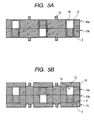
- Figs. 5A and 5B are main part sectional views of Fig. 2.
- Fig. 5A is a sectional view along line A-A of Fig. 2
- Fig. 5B is a sectional view along line B-B of Fig. 2.
- Fig. 5A is a sectional view in which the outside from the insulated winding part 12 is cut, and shows an assembly in which slot insulators 10a and 10b including the insulated winding parts 12 provided with the insertion grooves 16 are combined with each other.
- the winding parts 3 of the teeth of the two stator yokes constituting the duplexed resolver are disposed one by one in the vertically halved regions in the insertion grooves 16, respectively.
- a region in the insertion groove 16 in which the winding part 3 is not disposed is constructed as a space in which nothing is disposed.
- Fig. 5B is a sectional view in which the outside from the winding holding part 4 is cut.
- the winding holding part 4 is provided at the tip of the winding part 3.
- the longer side part 15 in contact with the side surface of the winding holding part 4 and the pair of shorter side parts in contact with the back surface of the winding holding part 4 are provided at the tip of the insulated winding part 12 of the slot insulator 10b.
- the longer side part 15 is provided at a position, and the pair of shorter side parts are provided at a position lower than the position of the longer side part 15 by the thickness of the winding holding part 4.
- the insertion groove 16 of the slot insulator 10a remains as a space where nothing is disposed.
- the longer side part 15 of the one slot insulator 10a, the pair of shorter side parts 14 and 14 of the one slot insulator 10a, the pair of shorter side parts 14 and 14 of the other slot insulator 10b, and the longer side part 15 of the other slot insulator 10b are disposed in order in one direction along the center axis of the cylindrical part 2 (the annular plate 11).
- the winding (not shown) is wound on the insulated winding parts 12 and 12 of both the slot insulator 10a and 10b in the state where the winding holding part 4 of the stator yoke 1 is supported or held by the pair of shorter side parts 14 and 14 of one of the slot insulators.
- the structure can be made simple.
- a pair of slot insulators are combined, and all shapes of the pairs of the insulated winding parts and all shapes of the pairs of the insulated winding holding parts can be made equal to one another. As a result, even if the position of the tooth changes vertically in the center axis direction in the duplexed resolver, the positions of the windings and the coil sizes can be made equal to one another.
- the coil sizes can be made equal to one another as set forth above, even if there is a structure in which the winding part of the tooth is not inserted in the insertion groove of the insulated winding part of the slot insulator, all the teeth have the common coil condition, and accordingly, a variation in output can be suppressed.
- the shapes of the pair of slot insulators can be made the common shape, the structure is simple and the manufacture becomes easy.
- the tooth is provided in the upper stator yoke or the lower stator yoke, it can be attached in common to the insulated winding holding part including the pair of shorter side parts and the longer side part.
- an arbitrary multiplexed resolver also has the above effects.
- Fig. 3 is a modified example of the slot insulator of Fig. 1.
- a slot insulator 20 has such a structure that the insulated winding part 12 having the insulated winding holding part 13 including the pair of shorter side parts 14 and 14 and the longer side part 15 in Fig. 1 and a insulated winding part 12 having a dummy insulated winding holding part 17 is alternately disposed in one direction of the circumference of the annular plate 11.
- the dummy insulated winding holding part 17 is formed as a plate-like part having an arc surface including a pair of shorter side parts 14 and 14 and a longer side part 15.
- the thickness of the dummy insulated winding holding part 17 in the radial direction is made equal to the thickness of the longer side part 15 in the radial direction of the annular plate 11.
- Fig. 4 is an assembly perspective view in which a pair of the slot insulators shown in Fig. 3 is attached to a stator yoke of a duplexed resolver from both sides.
- the pair of slot insulators 20 is attached to the upper and lower surfaces of the stator yoke assembly.
- the structure is such that in the pair of the upper and lower shorter side parts 14 and 14, the winding holding part 4 of the stator yoke 1 is attached to one of them, and the winding holding part 4 is not attached to the other.
- the slot insulator 20 side to which the winding holding part 4 of the stator yoke 1 is attached is constructed as the pair of shorter side parts 14 and 14, and the slot insulator 20 side to which the winding holding part 4 of the stator yoke 1 is not attached is constructed as the dummy insulated winding holding part 17.
- the dummy insulated winding holding part 17 is alternately provided in the upper and lower slot insulators 20 in the center axis direction (center axis direction of the annular plate) toward one direction of the circumferential direction (equivalent to the circumferential direction of the annular plate 11).
- Fig. 6A and 6B are explanation views of a case of a triplexed resolver.
- Fig. 6A is a structural view of an insulated winding holding part of a case of a triplexed resolver using the slot insulator of Fig. 1.
- Fig. 6B is structural view of an insulated winding holding part of a case of a triplexed resolver using the slot insulator of Fig. 3.
- a stator yoke is made to have an assembly structure of a yoke 1, a yoke 2 and a yoke 3.
- An insulated winding holding part of a slot insulator 1 is constructed such that a longer side part 15, a pair of shorter side parts 14 and 14 corresponding to the yoke 1, and a pair of shorter side parts 14 and 14 corresponding to the yoke 2 are continuously provided from above as shown in Fig. 6A.
- An insulated winding holding part of a slot insulator 2 is constructed such that a longer side part 15, and a pair of shorter side parts 14 and 14 corresponding to the yoke 3 are continuously provided from below as shown in Fig. 6A.
- the insulated winding holding part of the slot insulator is constructed in stator yoke units.
- An example (a1) is a mode of a case where the winding holding part 4 is provided in the yoke 1.
- An example (a2) is a mode of a case where the winding holding part 4 is provided in the yoke 2.
- An example (a3) is a mode of a case where the winding holding part 4 is provided in the yoke 3. Two insertion grooves 16 always remain as a space where nothing is disposed.
- a stator yoke is made to have an assembly structure of a yoke 1, a yoke 2 and a yoke 3.
- an insulated winding holding part of a slot insulator 1 is constructed such that a longer side part 15, and a pair of shorter side parts 14 and 14 corresponding to the yoke 1 are continuously provided from above as shown in Fig. 6B.
- An insulated winding holding part of a slot insulator 2 is a dummy insulated winding holding part 17a.
- a double longer side part 17b, and a pair of shorter side parts 14 and 14 corresponding to the yoke 2 are continuously provided from above as shown in Fig. 6B.
- a dummy insulated winding holding part 17c is provided in a slot insulator 2.
- an insulated winding holding part of a slot insulator 1 is a dummy insulated winding holding part 17a.
- An insulated winding holding part of a slot insulator 2 is constructed such that a longer side part 15 and a pair of shorter side parts 14 and 14 corresponding to the yoke 3 are continuously provided from below as shown in Fig. 6B.
- the definite order of from (a1) to (a3) is determined in the arrangement of the winding holding parts 4 of the stator yoke. Besides, also in the arrangement of the dummy insulated winding holding parts 17a and 17c, for example, the definite order from (b1) to (b3) is determined.
- the dummy insulated winding holding parts 17a and 17c have a feature that they do not include a pair of shorter side parts 14 and 14. Accordingly, the shape of the plate-like body part having the arc surface of the dummy insulated winding holding part is determined according to the degree of the multiplexing.
- inventions have inner rotor type structures.
- embodiment 4 a description will be given to an embodiment of an outer rotor type slot insulator and a multiplexed resolver using the slot insulator while quoting these structures.
- a plurality of insulated winding parts protruding outward in the radial direction of an annular plate are provided along the outer circumference of the annular plate, and the insulated winding holding parts are provided at the insulated winding parts.
- a stator yoke has a structure corresponding to the outer rotor type slot insulator.
- the explanation set forth above is quoted also for the respective structures of the outer rotor type stator yoke.
- the explanation as set forth above is quoted also for multiplexing of the outer rotor type resolver.
Landscapes
- Engineering & Computer Science (AREA)
- Power Engineering (AREA)
- Insulation, Fastening Of Motor, Generator Windings (AREA)
- Transmission And Conversion Of Sensor Element Output (AREA)
Applications Claiming Priority (1)
| Application Number | Priority Date | Filing Date | Title |
|---|---|---|---|
| JP2004321236A JP4647966B2 (ja) | 2004-11-04 | 2004-11-04 | 多重化レゾルバ用のスロットインシュレータとそれを用いた多重化レゾルバ |
Publications (1)
| Publication Number | Publication Date |
|---|---|
| EP1655818A1 true EP1655818A1 (de) | 2006-05-10 |
Family
ID=35708545
Family Applications (1)
| Application Number | Title | Priority Date | Filing Date |
|---|---|---|---|
| EP05020607A Withdrawn EP1655818A1 (de) | 2004-11-04 | 2005-09-21 | Nutisolierung und Mehrfach-Resolver mit einer solchen Nutisolierung |
Country Status (3)
| Country | Link |
|---|---|
| US (1) | US7256525B2 (de) |
| EP (1) | EP1655818A1 (de) |
| JP (1) | JP4647966B2 (de) |
Cited By (2)
| Publication number | Priority date | Publication date | Assignee | Title |
|---|---|---|---|---|
| CN107257173A (zh) * | 2017-07-25 | 2017-10-17 | 广东美的环境电器制造有限公司 | 用于集中绕组的电机定子的定子零件、电机定子及电机 |
| CN110323852A (zh) * | 2018-03-30 | 2019-10-11 | 株式会社丰田自动织机 | 旋转电机的定子以及旋转电机 |
Families Citing this family (9)
| Publication number | Priority date | Publication date | Assignee | Title |
|---|---|---|---|---|
| JP4710047B2 (ja) * | 2005-10-14 | 2011-06-29 | 康雄 飯島 | バリアブルリラクタンス型角度検出器 |
| US20080079101A1 (en) * | 2006-10-02 | 2008-04-03 | Chi Ai | Insulation frame device for a stator in a motor |
| TWM335451U (en) * | 2008-02-01 | 2008-07-01 | Ylc Prec Co Ltd | Multilayer power-generation device |
| DE102009020327A1 (de) * | 2009-05-07 | 2010-11-11 | Ltn Servotechnik Gmbh | Resolver |
| JP5710182B2 (ja) * | 2010-09-01 | 2015-04-30 | アイチエレック株式会社 | 電動機 |
| US9143015B2 (en) | 2012-05-23 | 2015-09-22 | Black & Decker Inc. | Brush holder for a brush assembly for a power tool motor |
| JP6615003B2 (ja) * | 2016-02-29 | 2019-12-04 | 株式会社ケーヒン | 空調用ブロアモータユニット |
| EP3316454A1 (de) | 2016-10-25 | 2018-05-02 | HILTI Aktiengesellschaft | Wickelstütze und stator |
| EP3389164B1 (de) * | 2017-04-11 | 2020-05-13 | Siemens Gamesa Renewable Energy A/S | Elektrischer generator mit reduzierten lagerströmen |
Citations (3)
| Publication number | Priority date | Publication date | Assignee | Title |
|---|---|---|---|---|
| JP2003023743A (ja) * | 2001-07-05 | 2003-01-24 | Asmo Co Ltd | 回転電機の電機子及びその製造方法並びにモータ |
| EP1404007A1 (de) * | 2002-09-25 | 2004-03-31 | Taiichi Miya | Vorrichtung und Verfahren zum Anschliessen eines Drehmelders |
| EP1473548A2 (de) * | 2003-04-28 | 2004-11-03 | Minebea Co., Ltd. | Redundantes Resolversystem |
Family Cites Families (6)
| Publication number | Priority date | Publication date | Assignee | Title |
|---|---|---|---|---|
| JPH0265055U (de) * | 1988-11-04 | 1990-05-16 | ||
| JP3353758B2 (ja) | 1999-09-27 | 2002-12-03 | ダイキン工業株式会社 | モータ用インシュレータ |
| JP2001169493A (ja) | 1999-12-07 | 2001-06-22 | Tamagawa Seiki Co Ltd | 絶縁キャップ構造及びレゾルバ構造 |
| JP4674679B2 (ja) | 2000-11-29 | 2011-04-20 | ミネベア株式会社 | バリアブルリラクタンスレゾルバの固定子構造 |
| JP2002233085A (ja) * | 2001-02-02 | 2002-08-16 | Oriental Motor Co Ltd | モータ用ステータおよびその組立方法 |
| JP2005207914A (ja) * | 2004-01-23 | 2005-08-04 | Minebea Co Ltd | 多重化レゾルバ |
-
2004
- 2004-11-04 JP JP2004321236A patent/JP4647966B2/ja not_active Expired - Fee Related
-
2005
- 2005-09-21 EP EP05020607A patent/EP1655818A1/de not_active Withdrawn
- 2005-09-22 US US11/232,040 patent/US7256525B2/en not_active Expired - Lifetime
Patent Citations (3)
| Publication number | Priority date | Publication date | Assignee | Title |
|---|---|---|---|---|
| JP2003023743A (ja) * | 2001-07-05 | 2003-01-24 | Asmo Co Ltd | 回転電機の電機子及びその製造方法並びにモータ |
| EP1404007A1 (de) * | 2002-09-25 | 2004-03-31 | Taiichi Miya | Vorrichtung und Verfahren zum Anschliessen eines Drehmelders |
| EP1473548A2 (de) * | 2003-04-28 | 2004-11-03 | Minebea Co., Ltd. | Redundantes Resolversystem |
Non-Patent Citations (1)
| Title |
|---|
| PATENT ABSTRACTS OF JAPAN vol. 2003, no. 05 12 May 2003 (2003-05-12) * |
Cited By (3)
| Publication number | Priority date | Publication date | Assignee | Title |
|---|---|---|---|---|
| CN107257173A (zh) * | 2017-07-25 | 2017-10-17 | 广东美的环境电器制造有限公司 | 用于集中绕组的电机定子的定子零件、电机定子及电机 |
| CN110323852A (zh) * | 2018-03-30 | 2019-10-11 | 株式会社丰田自动织机 | 旋转电机的定子以及旋转电机 |
| CN110323852B (zh) * | 2018-03-30 | 2021-03-12 | 株式会社丰田自动织机 | 旋转电机的定子以及旋转电机 |
Also Published As
| Publication number | Publication date |
|---|---|
| US20060091757A1 (en) | 2006-05-04 |
| JP4647966B2 (ja) | 2011-03-09 |
| JP2006136103A (ja) | 2006-05-25 |
| US7256525B2 (en) | 2007-08-14 |
Similar Documents
| Publication | Publication Date | Title |
|---|---|---|
| US8008831B2 (en) | Stator for rotary electric machine | |
| US7256525B2 (en) | Slot insulator and multiplexed resolver using same | |
| CN102474146B (zh) | 旋转电动机的定子 | |
| CN107852058B (zh) | 绝缘树脂覆盖方法和定子 | |
| US9154010B2 (en) | Armature and motor including armature | |
| US10707717B2 (en) | Stator and resolver | |
| CN101640440B (zh) | 旋转电机及其制造方法 | |
| US20030042817A1 (en) | Stator structure for rotary electric machine | |
| US20130313939A1 (en) | Motor | |
| US10389198B2 (en) | Stator for electric rotary machine | |
| JP3808641B2 (ja) | 固定子鉄心の製造方法および固定子鉄心の絶縁層被覆用モールド金型、並びに固定子鉄心 | |
| WO2010116928A1 (ja) | 電機におけるステータ | |
| US11171536B2 (en) | Cover assembly and motor including same | |
| JP2023129460A (ja) | ステータ構造 | |
| WO2024052989A1 (ja) | ステータコア | |
| CN107707045B (zh) | 定子铁芯、定子及电机 | |
| JP4680154B2 (ja) | 回転電機及びその製造方法 | |
| JP3717832B2 (ja) | 車両用薄型ブラシレスモータの集中配電部材 | |
| JP2022170669A (ja) | コイルセンタリング絶縁フィルムを含む、電気モータのステータ用の予備成形されたコイルアセンブリ | |
| US20180069459A1 (en) | Stator for rotary electric machine | |
| JP4900294B2 (ja) | 分割固定子製造方法 | |
| US20230018069A1 (en) | Stator for an electrical machine, electrical machine, and vehicle | |
| CN214013963U (zh) | 定子、电机和家电设备 | |
| JP2021010218A (ja) | ステータ構造およびレゾルバ | |
| CN116094277B (zh) | 电机和电器设备 |
Legal Events
| Date | Code | Title | Description |
|---|---|---|---|
| PUAI | Public reference made under article 153(3) epc to a published international application that has entered the european phase |
Free format text: ORIGINAL CODE: 0009012 |
|
| AK | Designated contracting states |
Kind code of ref document: A1 Designated state(s): AT BE BG CH CY CZ DE DK EE ES FI FR GB GR HU IE IS IT LI LT LU LV MC NL PL PT RO SE SI SK TR |
|
| AX | Request for extension of the european patent |
Extension state: AL BA HR MK YU |
|
| 17P | Request for examination filed |
Effective date: 20061019 |
|
| AKX | Designation fees paid |
Designated state(s): AT BE BG CH CY CZ DE DK EE ES FI FR GB GR HU IE IS IT LI LT LU LV MC NL PL PT RO SE SI SK TR |
|
| 17Q | First examination report despatched |
Effective date: 20081015 |
|
| STAA | Information on the status of an ep patent application or granted ep patent |
Free format text: STATUS: THE APPLICATION IS DEEMED TO BE WITHDRAWN |
|
| 18D | Application deemed to be withdrawn |
Effective date: 20090226 |