EP1655463B1 - Abgasreinigungsvorrichtung für motor - Google Patents
Abgasreinigungsvorrichtung für motor Download PDFInfo
- Publication number
- EP1655463B1 EP1655463B1 EP04747873.0A EP04747873A EP1655463B1 EP 1655463 B1 EP1655463 B1 EP 1655463B1 EP 04747873 A EP04747873 A EP 04747873A EP 1655463 B1 EP1655463 B1 EP 1655463B1
- Authority
- EP
- European Patent Office
- Prior art keywords
- reducing agent
- exhaust gas
- injection
- pressure
- compressed air
- Prior art date
- Legal status (The legal status is an assumption and is not a legal conclusion. Google has not performed a legal analysis and makes no representation as to the accuracy of the status listed.)
- Expired - Lifetime
Links
Images


Classifications
-
- F—MECHANICAL ENGINEERING; LIGHTING; HEATING; WEAPONS; BLASTING
- F01—MACHINES OR ENGINES IN GENERAL; ENGINE PLANTS IN GENERAL; STEAM ENGINES
- F01N—GAS-FLOW SILENCERS OR EXHAUST APPARATUS FOR MACHINES OR ENGINES IN GENERAL; GAS-FLOW SILENCERS OR EXHAUST APPARATUS FOR INTERNAL-COMBUSTION ENGINES
- F01N3/00—Exhaust or silencing apparatus having means for purifying, rendering innocuous, or otherwise treating exhaust
- F01N3/08—Exhaust or silencing apparatus having means for purifying, rendering innocuous, or otherwise treating exhaust for rendering innocuous
- F01N3/10—Exhaust or silencing apparatus having means for purifying, rendering innocuous, or otherwise treating exhaust for rendering innocuous by thermal or catalytic conversion of noxious components of exhaust
- F01N3/18—Exhaust or silencing apparatus having means for purifying, rendering innocuous, or otherwise treating exhaust for rendering innocuous by thermal or catalytic conversion of noxious components of exhaust characterised by methods of operation; Control
- F01N3/20—Exhaust or silencing apparatus having means for purifying, rendering innocuous, or otherwise treating exhaust for rendering innocuous by thermal or catalytic conversion of noxious components of exhaust characterised by methods of operation; Control specially adapted for catalytic conversion
- F01N3/206—Adding periodically or continuously substances to exhaust gases for promoting purification, e.g. catalytic material in liquid form, NOx reducing agents
- F01N3/2066—Selective catalytic reduction [SCR]
-
- B—PERFORMING OPERATIONS; TRANSPORTING
- B01—PHYSICAL OR CHEMICAL PROCESSES OR APPARATUS IN GENERAL
- B01D—SEPARATION
- B01D53/00—Separation of gases or vapours; Recovering vapours of volatile solvents from gases; Chemical or biological purification of waste gases, e.g. engine exhaust gases, smoke, fumes, flue gases, aerosols
- B01D53/34—Chemical or biological purification of waste gases
- B01D53/74—General processes for purification of waste gases; Apparatus or devices specially adapted therefor
- B01D53/86—Catalytic processes
- B01D53/90—Injecting reactants
-
- B—PERFORMING OPERATIONS; TRANSPORTING
- B01—PHYSICAL OR CHEMICAL PROCESSES OR APPARATUS IN GENERAL
- B01D—SEPARATION
- B01D53/00—Separation of gases or vapours; Recovering vapours of volatile solvents from gases; Chemical or biological purification of waste gases, e.g. engine exhaust gases, smoke, fumes, flue gases, aerosols
- B01D53/34—Chemical or biological purification of waste gases
- B01D53/92—Chemical or biological purification of waste gases of engine exhaust gases
- B01D53/94—Chemical or biological purification of waste gases of engine exhaust gases by catalytic processes
- B01D53/9495—Controlling the catalytic process
-
- F—MECHANICAL ENGINEERING; LIGHTING; HEATING; WEAPONS; BLASTING
- F01—MACHINES OR ENGINES IN GENERAL; ENGINE PLANTS IN GENERAL; STEAM ENGINES
- F01N—GAS-FLOW SILENCERS OR EXHAUST APPARATUS FOR MACHINES OR ENGINES IN GENERAL; GAS-FLOW SILENCERS OR EXHAUST APPARATUS FOR INTERNAL-COMBUSTION ENGINES
- F01N2610/00—Adding substances to exhaust gases
- F01N2610/02—Adding substances to exhaust gases the substance being ammonia or urea
-
- F—MECHANICAL ENGINEERING; LIGHTING; HEATING; WEAPONS; BLASTING
- F01—MACHINES OR ENGINES IN GENERAL; ENGINE PLANTS IN GENERAL; STEAM ENGINES
- F01N—GAS-FLOW SILENCERS OR EXHAUST APPARATUS FOR MACHINES OR ENGINES IN GENERAL; GAS-FLOW SILENCERS OR EXHAUST APPARATUS FOR INTERNAL-COMBUSTION ENGINES
- F01N2610/00—Adding substances to exhaust gases
- F01N2610/08—Adding substances to exhaust gases with prior mixing of the substances with a gas, e.g. air
-
- F—MECHANICAL ENGINEERING; LIGHTING; HEATING; WEAPONS; BLASTING
- F01—MACHINES OR ENGINES IN GENERAL; ENGINE PLANTS IN GENERAL; STEAM ENGINES
- F01N—GAS-FLOW SILENCERS OR EXHAUST APPARATUS FOR MACHINES OR ENGINES IN GENERAL; GAS-FLOW SILENCERS OR EXHAUST APPARATUS FOR INTERNAL-COMBUSTION ENGINES
- F01N2610/00—Adding substances to exhaust gases
- F01N2610/14—Arrangements for the supply of substances, e.g. conduits
- F01N2610/1493—Purging the reducing agent out of the conduits or nozzle
-
- F—MECHANICAL ENGINEERING; LIGHTING; HEATING; WEAPONS; BLASTING
- F01—MACHINES OR ENGINES IN GENERAL; ENGINE PLANTS IN GENERAL; STEAM ENGINES
- F01N—GAS-FLOW SILENCERS OR EXHAUST APPARATUS FOR MACHINES OR ENGINES IN GENERAL; GAS-FLOW SILENCERS OR EXHAUST APPARATUS FOR INTERNAL-COMBUSTION ENGINES
- F01N2900/00—Details of electrical control or of the monitoring of the exhaust gas treating apparatus
- F01N2900/06—Parameters used for exhaust control or diagnosing
- F01N2900/08—Parameters used for exhaust control or diagnosing said parameters being related to the engine
-
- Y—GENERAL TAGGING OF NEW TECHNOLOGICAL DEVELOPMENTS; GENERAL TAGGING OF CROSS-SECTIONAL TECHNOLOGIES SPANNING OVER SEVERAL SECTIONS OF THE IPC; TECHNICAL SUBJECTS COVERED BY FORMER USPC CROSS-REFERENCE ART COLLECTIONS [XRACs] AND DIGESTS
- Y02—TECHNOLOGIES OR APPLICATIONS FOR MITIGATION OR ADAPTATION AGAINST CLIMATE CHANGE
- Y02T—CLIMATE CHANGE MITIGATION TECHNOLOGIES RELATED TO TRANSPORTATION
- Y02T10/00—Road transport of goods or passengers
- Y02T10/10—Internal combustion engine [ICE] based vehicles
- Y02T10/12—Improving ICE efficiencies
Definitions
- the present invention relates to an exhaust gas purification apparatus of an engine (referred to hereunder as “exhaust gas purification apparatus”), which reduces the nitrogen oxide (NOx) in the exhaust gas using a liquid reducing agent.
- exhaust gas purification apparatus referred to hereunder as “exhaust gas purification apparatus”
- NOx nitrogen oxide
- a NOx reduction catalyst is arranged in an engine exhaust gas passage in order to convert NOx into harmless nitrogen (N 2 ) and oxygen (O 2 ) in an oxygenated atmosphere filled with excessive amount of oxygen. Furthermore, a construction is adopted in which an amount of liquid reducing agent as required according to the engine operating state, is supplied by injection from a nozzle into the exhaust gas upstream of the NOx reduction catalyst, in order to enhance the efficiency of NOx purification in the NOx reduction catalyst.
- US6912846 or WO02/24311A describes a technique for metering a reducing agent for removing nitrogen oxides from exhaust gases; and JP2002-332825 describes a technique for increasing the NOx cleaning efficiency of a NOx reduction catalyst.
- an object of the present invention is to provide an exhaust gas purification apparatus in which clogging in a nozzle is prevented, and a failure in the reduction and purification of NOx due to a shortage in the supply of the liquid reducing agent is suppressed, by supplying high pressure air into the nozzle when the injection supply of the liquid reducing agent is stopped.
- an exhaust gas purification apparatus according to claim 1, and a method of controlling an exhaust gas purification apparatus according to claim 3.
- the injection flow rate of the liquid reducing agent which is injection supplied into the engine exhaust gas passage from the nozzle injection hole, becomes zero, high pressure air is supplied into the nozzle for a predetermined period.
- high pressure air is supplied into the nozzle for a predetermined period.
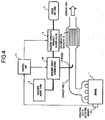
- Figure 1 shows the overall construction of an exhaust gas purification apparatus.
- a NOx reduction catalyst 3 for reducing and purifying the NOx in an exhaust gas is provided in an exhaust pipe 2 constituting an exhaust gas passage of an engine 1.
- the NOx reduction catalyst 3 is of a construction where for example a zeolite type active ingredient, is supported by a monolithic type catalyst support having a honeycomb shaped cross-section comprising ceramic cordierite, or an Fe-Cr-Al type heat-resistant steel.
- the catalyst ingredient supported by the catalyst support receives a supply of a liquid reducing agent such as a urea water solution, gasoline, a diesel oil, alcohol or the like, and is activated, to thereby effectively convert the NOx into a harmless substance.
- a nozzle 4 is provided on the exhaust gas upstream side of the NOx reduction catalyst 3, to injection-supply a liquid reducing agent from an injection hole which opens into the exhaust pipe 2.
- Compressed air which is pressurized to between 700 and 1000kPa, is stored in an air reservoir tank 5.
- the compressed air stored in the air reservoir tank 5 passes through a solenoid-operated openably closed valve 6, which is a normally-closed valve, and a pressure-reducing valve 7 (pressure-reducing device), in sequence, and is supplied to a reducing agent dosing device 8.
- the air reservoir tank 5 may be shared with an air reservoir tank provided for other purposes.
- liquid reducing agent stored in a reducing agent tank 9 is supplied to the reducing agent dosing device 8.
- the reducing agent dosing device 8 doses the liquid reducing agent to the compressed air to transform it into an atomized state, by the operation of a built-in pump, and afterwards supplies it to the nozzle 4.
- the dosing flow rate of the liquid reducing agent that is, the injection flow rate of the liquid reducing agent, can be optionally varied by controlling the operation of the pump.
- the reducing agent dosing device 8 has the interior thereof in communication with the nozzle 4 such that the supplied compressed air can be constantly supplied to the nozzle 4 at all times.
- the compressed air stored in the air reservoir tank 5 is branched after passing through the solenoid-operated openably closed valve 6, and is supplied to a purge air tank 11 via a check valve 10. Therefore, the purge air tank 11 stores compressed air substantially the same pressure as the air reservoir tank 5.
- the check valve 10 is installed in a direction whereby it prevents the compressed air from flowing back from the purge air tank 11 to downstream of the solenoid-operated openably closed valve 6.
- the compressed air stored in the purge air tank 11 is supplied to the reducing agent dosing device 8 via a solenoid-operated openably closed valve 12 that is also a normally-closed valve.
- the engine 1 is provided with an operating state detecting sensor 13 (operating state detecting device) for detecting its rotational speed and load.
- an operating state detecting sensor 13 operating state detecting device
- a control unit 14 with a built-in computer, receives the rotational speed and load from the operating state detecting sensor 13, and operates and controls; the built-in pump in the reducing agent dosing device 8, the solenoid-operated openably closed valve 6, and the solenoid-operated openably closed valve 12, executing a control program stored in a ROM (Read Only Memory).
- ROM Read Only Memory
- the air reservoir tank 5, the solenoid-operated openably closed valve 6, the pressure-reducing valve 7, the reducing agent dosing device 8, the reducing agent tank 9, and the control unit 14, constitute a reducing agent injection supply device. Furthermore, the purge air tank 11, the solenoid-operated openably closed valve 12, and the control unit 14 constitute a high pressure air supply device.
- the control unit 14 reads the rotational speed and load from the operating state detecting sensor 13, and calculates the dosing flow rate of the liquid reducing agent required for the reduction and purification of the NOx in the exhaust gas. Then, when the dosing flow rate of the liquid reducing agent is not zero, the control unit 14 opens the solenoid-operated openably closed valve 6, and operates and controls the built-in pump in the reducing agent dosing device 8 according to the dosing flow rate. As a result, the compressed air stored in the air reservoir tank 5 is reduced to a predetermined pressure by the pressure-reducing valve 7, and supplied to the reducing agent dosing device 8.
- liquid reducing agent with the flow rate required for the reduction and purification of the NOx in the exhaust gas is mixed with the compressed air whose pressure is reduced, and transformed into an atomized state, and is injection supplied from the nozzle 4 into the exhaust pipe 2.
- the liquid reducing agent injection-supplied from the nozzle 4 is supplied to the NOx reduction catalyst 3 and mixed with the exhaust gas at the same time, and the NOx in the exhaust gas is reduced and purified in the NOx reduction catalyst 3.
- the control unit 14 closes the solenoid-operated openably closed valve 6, stops the operation of the built-in pump in the reducing agent dosing device 8, and stops the injection-supply of the liquid reducing agent to the inside of the exhaust pipe 2. Afterwards, the control unit 14 opens the solenoid-operated openably closed valve 12 for a predetermined period, to thereby supply the compressed air stored in the purge air tank 11 to the reducing agent dosing device 8, and inject the compressed air from the injection hole of the nozzle 4 to the inside of the exhaust pipe 2.
- the pressure of the purge air tank 11 is reduced due to the consumption of the compressed air stored therein.
- the solenoid-operated openably closed valve 6 is opened, the compressed air stored in the air reservoir tank 5 is automatically supplied to the purge air tank 11 via the check valve 10. Therefore, the compressed air in the purge air tank 11 is maintained within a predetermined range.
- FIG 2 shows the overall construction of another exhaust gas purification apparatus.
- the descriptions of constructions identical to those of the apparatus of Figure 1 have been omitted by utilizing the same reference symbols, in order to avoid duplicated descriptions (the same applies for the other embodiments hereunder).
- Aconstruction is adopted in which compressed air is supplied to a purge air tank 11 using an air compressor 20 for pressurizing the atmosphere to a predetermined pressure.
- the air compressor 20 may be operated and controlled according to the output from a pressure switch installed for example in the purge air tank 11, so that the pressure of the compressed air stored in the purge air tank 11 is within a predetermined range.
- compressed air of an optional pressure can be supplied to the purge air tank 11 using the air compressor 20, regardless of the pressure of the compressed air stored in the air reservoir tank 5. Therefore, if the supply pressure of the compressed air from the air compressor 20 is set to a pressure whereby liquid reducing agent remaining in the nozzle 4 can be forcibly discharged, clogging of the nozzle 4 can be effectively prevented.
- FIG. 3 shows the overall construction of an embodiment of an exhaust gas purification apparatus according to the present invention.
- a construction is adopted in which, instead of the pressure-reducing valve 7 in the first and second embodiments, a pressure-reducing valve 30 is provided that can be switched to either let compressed air stored in the air reservoir tank 5 pass through directly, or to reduce the pressure to a predetermined pressure as it passes through, and the switching is controlled by a control unit 14.
- the control unit 14 opens a solenoid-operated openably closed valve 6 when the liquid reducing agent is injection-supplied, and controls the switching of the pressure-reducing valve 30 so as to reduce the pressure of the compressed air. Furthermore, the control unit 14 opens the solenoid-operated openably closed valve 6 for a predetermined period after injection of the liquid reducing agent is stopped, and also controls the switching of the pressure-reducing valve 30 so that the compressed air passes through it directly. Therefore, when the liquid reducing agent is injection-supplied, compressed air stored in the air reservoir tank 5 is reduced in pressure, and supplied to a reducing agent dosing device 8. On the other hand, after injection of the liquid reducing agent is stopped, it is supplied to the reducing agent dosing device 8 directly for a predetermined period.
- the number of solenoid-operated openably closed valves may be reduced, and also a purge air tank and a check valve are not required. Moreover, it is possible to reduce the parts count by sharing parts, thus forming a simple construction, and hence the space and cost can be reduced.
- FIG. 4 shows the overall construction of another exhaust gas purification apparatus.
- a construction is adopted in which, when a liquid reducing agent is injection-supplied, compressed air is not used, but the liquid reducing agent is pressurized by a reducing agent dosing device 40, for injection supply.
- an exhaust gas purification apparatus when the injection-supply of a liquid reducing agent is stopped, the liquid reducing agent remaining in the nozzle is forcibly discharged. Therefore, the occurrence of clogging inside the nozzle is prevented, and a failure in the reduction and purification of the NOx, caused by a shortage in the supply of the liquid reducing agent can be suppressed, which is extremely advantageous.
Landscapes
- Engineering & Computer Science (AREA)
- Chemical & Material Sciences (AREA)
- Chemical Kinetics & Catalysis (AREA)
- Health & Medical Sciences (AREA)
- Environmental & Geological Engineering (AREA)
- Biomedical Technology (AREA)
- Analytical Chemistry (AREA)
- General Chemical & Material Sciences (AREA)
- Oil, Petroleum & Natural Gas (AREA)
- Combustion & Propulsion (AREA)
- Toxicology (AREA)
- Mechanical Engineering (AREA)
- General Engineering & Computer Science (AREA)
- Exhaust Gas After Treatment (AREA)
- Exhaust Gas Treatment By Means Of Catalyst (AREA)
Claims (3)
- Abgasreinigungsvorrichtung eines Motors (1), umfassend:einen Stickoxid-Reduktionskatalysator (3), der in einem Motorabgasdurchgang (2) angeordnet ist, um Stickoxid im Abgas unter Verwendung eines flüssigen Reduktionsmittels zu reduzieren und zu reinigen;eine Düse (4) mit einem Einspritzloch, das sich in den Abgasdurchgang öffnet und auf einer Abgasstromaufwärtsseite des Stickoxid-Reduktionskatalysators positioniert ist;eine Erkennungsvorrichtung (13) für einen Betriebszustand, die einen Motorbetriebszustand erkennt;eine Einspritzversorgungsvorrichtung (8) für Reduktionsmittel, die der Einspritzversorgung eines flüssigen Reduktionsmittels aus dem Düseneinspritzloch in den Abgasdurchgang auf dem Motorbetriebszustand basierend fähig ist, der von der Erkennungsvorrichtung für Betriebszustand erkannt wurde; undeine Steuereinheit mit eingebautem Computer (14);ein magnetisch betätigtes öffenbar geschlossenes Ventil (6) zwischen einer Hochdruck-Luftversorgungsvorrichtung (5) und der Einspritzversorgungsvorrichtung für das Reduktionsmittel;und gekennzeichnet durch Umfassen einer Druckminderungsvorrichtung (30) zwischen dem öffenbar geschlossenen Ventil und der Einspritzversorgungsvorrichtung für Reduktionsmittel, und schaltbar, um entweder Druckluft direkt dort hindurch strömen zu lassen oder den Druck der Druckluft zu mindern, sowie sie dort hindurch strömt;wobei die Steuereinheit konfiguriert ist, das öffenbar geschlossene Ventil zu öffnen und die Druckminderungsvorrichtung zu steuern, um den Druck der dort hindurch strömenden Druckluft zu mindern, wenn das flüssige Reduktionsmittel zugeführt wird; und die Steuereinheit konfiguriert ist, das öffenbar geschlossene Ventil für eine vorbestimmte Zeitdauer zu öffnen nach dem die Einspritzung des flüssigen Reduktionsmittels gestoppt ist und die Druckminderungsvorrichtung zu steuern um die Druckluft direkt dort hindurch strömen zu lassen.
- Abgasreinigungsvorrichtung eines Motors gemäß Anspruch 1, wobei die Einspritzversorgungsvorrichtung für Reduktionsmittel konfiguriert ist, die Druckluft, deren Druck gemindert ist, mit dem flüssigen Reduktionsmittel zu mischen, um es in einen atomisierten Zustand zu transformieren, und danach diese Mischung mittels Einspritzversorgung aus dem Düseneinspritzloch in den Abgasdurchgang zu spritzen.
- Verfahren zur Steuerung einer Abgasreinigungsvorrichtung, wobei die Vorrichtung umfasst:einen Stickoxid-Reduktionskatalysator (3), der in einem Motorabgasdurchgang (2) angeordnet ist, um Stickoxid im Abgas unter Verwendung eines flüssigen Reduktionsmittels zu reduzieren und zu reinigen;eine Düse (4) mit einem Einspritzloch, das sich in den Abgasdurchgang öffnet und auf einer Abgasstromaufwärtsseite des Stickoxid-Reduktionskatalysators positioniert ist;eine Erkennungsvorrichtung (13) für einen Betriebszustand, die einen Motorbetriebszustand erkennt;eine Einspritzversorgungsvorrichtung (8) für Reduktionsmittel, die der Einspritzversorgung eines flüssigen Reduktionsmittels aus dem Düseneinspritzloch in den Abgasdurchgang auf dem Motorbetriebszustand basierend fähig ist, der von der Erkennungsvorrichtung für Betriebszustand erkannt wurde;ein magnetisch betätigtes öffenbar geschlossenes Ventil (6) zwischen einer Hochdruck-Luftversorgungsvorrichtung (5) und der Einspritzversorgungsvorrichtung für das Reduktionsmittel; undwobei das Verfahren durch eine Druckminderungsvorrichtung (30) gekennzeichnet ist, die zwischen dem öffenbar geschlossenen Ventil und der Einspritzversorgungsvorrichtung für Reduktionsmittel platziert ist, und schaltbar ist, um entweder Druckluft direkt dort hindurch strömen zu lassen oder den Druck der Druckluft zu mindern, sowie sie dort hindurch strömt;wobei das Verfahren ferner folgende Schritte umfasst: Öffnen des öffenbar geschlossenen Ventils und Steuern der Druckminderungsvorrichtung, um den Druck der dort hindurch strömenden Druckluft zu mindern, wenn das flüssige Reduktionsmittel zugeführt wird; und Öffnen des öffenbar geschlossenen Ventils für eine vorbestimmte Zeitdauer nach dem die Einspritzung des flüssigen Reduktionsmittels gestoppt ist und Steuern der Druckminderungsvorrichtung, um die Druckluft direkt dort hindurch strömen zu lassen.
Applications Claiming Priority (2)
| Application Number | Priority Date | Filing Date | Title |
|---|---|---|---|
| JP2003282359A JP4152833B2 (ja) | 2003-07-30 | 2003-07-30 | エンジンの排気浄化装置 |
| PCT/JP2004/010487 WO2005012702A1 (ja) | 2003-07-30 | 2004-07-23 | エンジンの排気浄化装置 |
Publications (3)
| Publication Number | Publication Date |
|---|---|
| EP1655463A1 EP1655463A1 (de) | 2006-05-10 |
| EP1655463A4 EP1655463A4 (de) | 2009-12-23 |
| EP1655463B1 true EP1655463B1 (de) | 2016-07-06 |
Family
ID=34113775
Family Applications (1)
| Application Number | Title | Priority Date | Filing Date |
|---|---|---|---|
| EP04747873.0A Expired - Lifetime EP1655463B1 (de) | 2003-07-30 | 2004-07-23 | Abgasreinigungsvorrichtung für motor |
Country Status (5)
| Country | Link |
|---|---|
| US (1) | US7571599B2 (de) |
| EP (1) | EP1655463B1 (de) |
| JP (1) | JP4152833B2 (de) |
| CN (1) | CN100432385C (de) |
| WO (1) | WO2005012702A1 (de) |
Families Citing this family (36)
| Publication number | Priority date | Publication date | Assignee | Title |
|---|---|---|---|---|
| JP2005105970A (ja) * | 2003-09-30 | 2005-04-21 | Nissan Diesel Motor Co Ltd | エンジンの排気浄化装置 |
| DE102005006260A1 (de) * | 2005-02-11 | 2006-08-24 | Daimlerchrysler Ag | Zugabevorrichtung zur Zugabe von Reduktionsmittel in eine Abgasleitung einer Brennkraftmaschine |
| JP4592504B2 (ja) * | 2005-06-09 | 2010-12-01 | 三菱ふそうトラック・バス株式会社 | 排気浄化装置 |
| WO2007008121A1 (en) * | 2005-07-07 | 2007-01-18 | Volvo Lastvagnar Ab | Method, device and computer program product for diagnosing of at least one exhaust emission control unit |
| JP4650241B2 (ja) * | 2005-11-30 | 2011-03-16 | トヨタ自動車株式会社 | 内燃機関の排気システム |
| SE529591C2 (sv) * | 2006-02-08 | 2007-09-25 | Stt Emtec Ab | Insprutningsanordning |
| JP4684150B2 (ja) * | 2006-03-30 | 2011-05-18 | 三菱ふそうトラック・バス株式会社 | エア回路の制御装置 |
| US20080034733A1 (en) * | 2006-08-14 | 2008-02-14 | Miller Robert L | Fuel supply component purging system |
| US8499739B2 (en) | 2006-08-31 | 2013-08-06 | Caterpillar Inc. | Injector having tangentially oriented purge line |
| EP2080889A4 (de) * | 2006-11-09 | 2011-02-09 | Nissan Diesel Motor Co | Umgebungslufttemperaturdetektor und abgasreinigungsvorrichtung |
| US8006482B2 (en) * | 2007-03-02 | 2011-08-30 | Caterpillar Inc. | Method of purging fluid injector by heating |
| US8215100B2 (en) | 2007-03-02 | 2012-07-10 | Caterpillar Inc. | Regeneration device having external check valve |
| US7874148B2 (en) * | 2007-03-15 | 2011-01-25 | Deere & Company | Regeneration system and method for particulate traps |
| JP4174685B1 (ja) * | 2007-05-31 | 2008-11-05 | 三菱自動車工業株式会社 | 内燃機関の排気浄化装置 |
| US7958721B2 (en) | 2007-06-29 | 2011-06-14 | Caterpillar Inc. | Regeneration system having integral purge and ignition device |
| US8281570B2 (en) * | 2007-08-09 | 2012-10-09 | Caterpillar Inc. | Reducing agent injector having purge heater |
| WO2009081228A1 (en) * | 2007-12-21 | 2009-07-02 | Renault Trucks | Apparatus and method for injection of a fluid for an exhaust gases treatment device |
| US20100154387A1 (en) * | 2008-12-19 | 2010-06-24 | Toyota Jidosha Kabushiki Kaisha | Abnormality detection device for reductant addition valve |
| DE102009014831A1 (de) * | 2009-03-25 | 2010-09-30 | Daimler Ag | Verfahren zum Betreiben eines Reduktionsmittelversorgungssystems |
| SE536318C2 (sv) | 2010-06-21 | 2013-08-20 | Scania Cv Ab | Förfarande och anordning för att avlägsna reduktionsmedel ur en doseringsenhet vid ett SCR-system |
| SE536316C2 (sv) * | 2010-06-21 | 2013-08-20 | Scania Cv Ab | Förfarande och anordning för att avlägsna bränsle ur en doseringsenhet vid ett HC-doseringssystem |
| SE537642C2 (sv) * | 2010-06-21 | 2015-09-08 | Scania Cv Ab | Förfarande och anordning vid kylning av en doseringsenhet för reduktionsmedel |
| US9145817B2 (en) * | 2010-11-08 | 2015-09-29 | Bosch Corporation | Reducing agent injection valve abnormality detection unit and reducing agent supply apparatus |
| JP5586446B2 (ja) * | 2010-12-16 | 2014-09-10 | Udトラックス株式会社 | エンジンの排気管噴射装置 |
| JP5906637B2 (ja) * | 2011-09-28 | 2016-04-20 | いすゞ自動車株式会社 | 異物除去方法及び選択還元触媒システム |
| JP6094974B2 (ja) * | 2012-02-22 | 2017-03-15 | パナソニックIpマネジメント株式会社 | 植物栽培システム |
| CN103291421B (zh) | 2012-02-23 | 2016-06-08 | 天纳克(苏州)排放系统有限公司 | 空气辅助式还原剂计量喷射系统 |
| WO2014143851A1 (en) * | 2013-03-15 | 2014-09-18 | Cummins Ip, Inc. | Pump purge for urea dosing system |
| JP6151980B2 (ja) * | 2013-06-17 | 2017-06-21 | 株式会社荏原製作所 | 粉体排出システム |
| US10473014B2 (en) * | 2013-12-23 | 2019-11-12 | Baohua Qi | Low pressure atomizing injector |
| SE540367C2 (sv) * | 2014-06-12 | 2018-08-14 | Scania Cv Ab | System och metod för evakuering av fluid i rörledningar i ett fordon |
| US11585253B2 (en) | 2015-08-07 | 2023-02-21 | Cummins Emission Solutions Inc. | Converging liquid reductant injector nozzle in selective catalytic reduction systems |
| KR102466782B1 (ko) * | 2016-05-27 | 2022-11-16 | 에이치에스디엔진 주식회사 | 환원제 공급 시스템 |
| CN108479347B (zh) * | 2018-04-13 | 2020-05-05 | 宁波清智环保科技有限公司 | 环保气体净化装置 |
| DE112019007644T5 (de) * | 2019-08-22 | 2022-05-19 | Cummins Emission Solutions Inc. | Systeme und Verfahren zum Erzeugen von Ammoniak |
| JP7696286B2 (ja) * | 2021-12-14 | 2025-06-20 | ヤンマーホールディングス株式会社 | 還元剤供給装置 |
Family Cites Families (18)
| Publication number | Priority date | Publication date | Assignee | Title |
|---|---|---|---|---|
| JPH0615815B2 (ja) * | 1987-06-22 | 1994-03-02 | 三菱自動車工業株式会社 | ディ−ゼルパティキュレ−トトラップのバ−ナ−による再生装置 |
| KR950012137B1 (ko) * | 1989-02-02 | 1995-10-14 | 닛뽄 쇼크바이 카가꾸 고오교오 가부시기가이샤 | 디이젤엔진 배기가스 중의 질소산화물 제거방법 |
| CA2088713C (en) | 1992-02-24 | 1999-11-16 | Hans Thomas Hug | Cleaning exhaust gases from combustion installations |
| EP0617199B1 (de) * | 1993-03-26 | 1996-01-31 | Siemens Aktiengesellschaft | Katalysator zur Stickoxidminderung im Abgas eines Verbrennungsmotors |
| JP2937738B2 (ja) | 1994-04-05 | 1999-08-23 | 株式会社新潟鉄工所 | 排煙脱硝装置の還元剤噴霧装置 |
| JP3022601B2 (ja) * | 1994-09-13 | 2000-03-21 | シーメンス アクチエンゲゼルシヤフト | 排気ガス浄化装置に液体を供給する方法及び装置 |
| DE4436397B4 (de) * | 1994-10-12 | 2006-06-08 | Robert Bosch Gmbh | Einrichtung zum Nachbehandeln von Abgasen |
| DE19531028A1 (de) * | 1995-08-23 | 1997-02-27 | Siemens Ag | Verfahren zur Abgasreinigung und Abgas-Reinigungseinrichtung für einen Verbrennungsmotor |
| DE19726392A1 (de) * | 1997-06-21 | 1998-12-24 | Bosch Gmbh Robert | Gemischabgabevorrichtung |
| DE19738859A1 (de) * | 1997-09-05 | 1999-03-11 | Bosch Gmbh Robert | Gemischabgabevorrichtung |
| JP3565035B2 (ja) * | 1998-07-10 | 2004-09-15 | 三菱ふそうトラック・バス株式会社 | 燃焼排ガス用NOx還元システム |
| JP2000027627A (ja) | 1998-07-13 | 2000-01-25 | Hino Motors Ltd | 排気ガス浄化触媒用還元剤保温装置及びそれを組込んだ排気ガス浄化装置 |
| JP2000257419A (ja) * | 1999-03-03 | 2000-09-19 | Toyota Motor Corp | 排気浄化方法及び装置 |
| US6167698B1 (en) * | 1999-12-21 | 2001-01-02 | Ford Motor Company | Exhaust gas purification system for a lean burn engine |
| JP3613676B2 (ja) * | 2000-07-24 | 2005-01-26 | トヨタ自動車株式会社 | 内燃機関の排気浄化装置 |
| DE10047516A1 (de) * | 2000-09-22 | 2002-04-18 | Bosch Gmbh Robert | Verfahren und Vorrichtung zur Dosierung eines Reduktionsmittels zur Entfernung von Stickoxiden aus Abgasen |
| JP3545691B2 (ja) | 2000-09-27 | 2004-07-21 | 日野自動車株式会社 | 排気浄化装置の運転方法 |
| JP4131783B2 (ja) * | 2001-05-09 | 2008-08-13 | 日産ディーゼル工業株式会社 | 内燃機関の排気浄化装置 |
-
2003
- 2003-07-30 JP JP2003282359A patent/JP4152833B2/ja not_active Expired - Lifetime
-
2004
- 2004-07-23 EP EP04747873.0A patent/EP1655463B1/de not_active Expired - Lifetime
- 2004-07-23 CN CNB2004800217588A patent/CN100432385C/zh not_active Expired - Lifetime
- 2004-07-23 WO PCT/JP2004/010487 patent/WO2005012702A1/ja not_active Ceased
- 2004-07-23 US US10/566,367 patent/US7571599B2/en not_active Expired - Lifetime
Also Published As
| Publication number | Publication date |
|---|---|
| EP1655463A4 (de) | 2009-12-23 |
| CN100432385C (zh) | 2008-11-12 |
| WO2005012702A1 (ja) | 2005-02-10 |
| CN1839252A (zh) | 2006-09-27 |
| US20070186542A1 (en) | 2007-08-16 |
| EP1655463A1 (de) | 2006-05-10 |
| JP2005048677A (ja) | 2005-02-24 |
| US7571599B2 (en) | 2009-08-11 |
| JP4152833B2 (ja) | 2008-09-17 |
Similar Documents
| Publication | Publication Date | Title |
|---|---|---|
| EP1655463B1 (de) | Abgasreinigungsvorrichtung für motor | |
| US7716918B2 (en) | Method of exhaust gas purification and exhaust gas purification system | |
| US7963109B2 (en) | Guide structure and exhaust gas purification device | |
| US20100005787A1 (en) | Exhaust gas purification apparatus for engine | |
| KR20060069355A (ko) | 환원제 첨가 조절 방법 | |
| JP6058878B2 (ja) | 排ガス浄化装置 | |
| JP2007198316A (ja) | 内燃機関の排気浄化装置及び排気浄化方法 | |
| US20110154808A1 (en) | Exhaust gas purification apparatus for diesel engine | |
| CN100510335C (zh) | 具有废气排放控制的发动机驱动的车辆 | |
| JP3628277B2 (ja) | エンジンの排ガス浄化装置 | |
| JPH07243322A (ja) | エンジンのNOx低減装置 | |
| US8105542B2 (en) | Engine exhaust gas purifier | |
| EP2460996B1 (de) | Abgasreiniger für Verbrennungsmotor | |
| JP2008157188A (ja) | 排気浄化装置 | |
| JP5778951B2 (ja) | 排ガス浄化装置 | |
| JP2005248924A (ja) | エンジンの排気浄化装置 | |
| JP3905264B2 (ja) | エンジンの排ガス浄化装置 | |
| JP4196593B2 (ja) | 内燃機関の排気浄化装置 | |
| JP2012062818A (ja) | エンジンの排ガス浄化装置 | |
| JPS5979024A (ja) | デイ−ゼルエンジンの排気ガス浄化装置 | |
| JP3570524B2 (ja) | エンジンの排ガス浄化装置 | |
| JP2010150978A (ja) | 排気浄化装置 | |
| WO2005078252A1 (ja) | エンジンの排ガス浄化装置 | |
| JP2002371835A (ja) | 内燃機関の排気ガス浄化装置 | |
| JP2007113401A (ja) | エンジンの排ガス浄化装置 |
Legal Events
| Date | Code | Title | Description |
|---|---|---|---|
| PUAI | Public reference made under article 153(3) epc to a published international application that has entered the european phase |
Free format text: ORIGINAL CODE: 0009012 |
|
| 17P | Request for examination filed |
Effective date: 20060130 |
|
| AK | Designated contracting states |
Kind code of ref document: A1 Designated state(s): DE NL SE |
|
| DAX | Request for extension of the european patent (deleted) | ||
| RBV | Designated contracting states (corrected) |
Designated state(s): DE NL SE |
|
| A4 | Supplementary search report drawn up and despatched |
Effective date: 20091124 |
|
| RIC1 | Information provided on ipc code assigned before grant |
Ipc: F01N 3/20 20060101ALI20091118BHEP Ipc: F01N 3/36 20060101AFI20050215BHEP Ipc: F01N 3/08 20060101ALI20091118BHEP |
|
| 17Q | First examination report despatched |
Effective date: 20101206 |
|
| GRAP | Despatch of communication of intention to grant a patent |
Free format text: ORIGINAL CODE: EPIDOSNIGR1 |
|
| INTG | Intention to grant announced |
Effective date: 20160202 |
|
| GRAS | Grant fee paid |
Free format text: ORIGINAL CODE: EPIDOSNIGR3 |
|
| GRAA | (expected) grant |
Free format text: ORIGINAL CODE: 0009210 |
|
| AK | Designated contracting states |
Kind code of ref document: B1 Designated state(s): DE NL SE |
|
| REG | Reference to a national code |
Ref country code: DE Ref legal event code: R081 Ref document number: 602004049548 Country of ref document: DE Owner name: VOLVO TRUCK CORPORATION, SE Free format text: FORMER OWNER: NISSAN DIESEL MOTOR CO., LTD., AGEO, SAITAMA, JP |
|
| REG | Reference to a national code |
Ref country code: DE Ref legal event code: R096 Ref document number: 602004049548 Country of ref document: DE |
|
| REG | Reference to a national code |
Ref country code: SE Ref legal event code: TRGR |
|
| REG | Reference to a national code |
Ref country code: NL Ref legal event code: FP |
|
| REG | Reference to a national code |
Ref country code: DE Ref legal event code: R097 Ref document number: 602004049548 Country of ref document: DE |
|
| PLBE | No opposition filed within time limit |
Free format text: ORIGINAL CODE: 0009261 |
|
| STAA | Information on the status of an ep patent application or granted ep patent |
Free format text: STATUS: NO OPPOSITION FILED WITHIN TIME LIMIT |
|
| 26N | No opposition filed |
Effective date: 20170407 |
|
| REG | Reference to a national code |
Ref country code: DE Ref legal event code: R081 Ref document number: 602004049548 Country of ref document: DE Owner name: VOLVO TRUCK CORPORATION, SE Free format text: FORMER OWNER: NISSAN DIESEL MOTOR CO., LTD., AGEO-SHI, SAITAMA-KEN, JP |
|
| REG | Reference to a national code |
Ref country code: NL Ref legal event code: PD Owner name: VOLVO TRUCK CORPORATION; SE Free format text: DETAILS ASSIGNMENT: CHANGE OF OWNER(S), ASSIGNMENT; FORMER OWNER NAME: VOLVO GROUP SWEDEN AB Effective date: 20211125 |
|
| PGFP | Annual fee paid to national office [announced via postgrant information from national office to epo] |
Ref country code: NL Payment date: 20230726 Year of fee payment: 20 |
|
| PGFP | Annual fee paid to national office [announced via postgrant information from national office to epo] |
Ref country code: SE Payment date: 20230726 Year of fee payment: 20 Ref country code: DE Payment date: 20230726 Year of fee payment: 20 |
|
| REG | Reference to a national code |
Ref country code: DE Ref legal event code: R071 Ref document number: 602004049548 Country of ref document: DE |
|
| REG | Reference to a national code |
Ref country code: NL Ref legal event code: MK Effective date: 20240722 |
|
| REG | Reference to a national code |
Ref country code: SE Ref legal event code: EUG |