EP1653083B1 - Zahnradpumpe mit einer radialen und axialen Stützlagerung - Google Patents
Zahnradpumpe mit einer radialen und axialen Stützlagerung Download PDFInfo
- Publication number
- EP1653083B1 EP1653083B1 EP05022993.9A EP05022993A EP1653083B1 EP 1653083 B1 EP1653083 B1 EP 1653083B1 EP 05022993 A EP05022993 A EP 05022993A EP 1653083 B1 EP1653083 B1 EP 1653083B1
- Authority
- EP
- European Patent Office
- Prior art keywords
- housing
- drive shaft
- gear pump
- supporting
- sealing
- Prior art date
- Legal status (The legal status is an assumption and is not a legal conclusion. Google has not performed a legal analysis and makes no representation as to the accuracy of the status listed.)
- Expired - Lifetime
Links
Images

Classifications
-
- F—MECHANICAL ENGINEERING; LIGHTING; HEATING; WEAPONS; BLASTING
- F01—MACHINES OR ENGINES IN GENERAL; ENGINE PLANTS IN GENERAL; STEAM ENGINES
- F01C—ROTARY-PISTON OR OSCILLATING-PISTON MACHINES OR ENGINES
- F01C21/00—Component parts, details or accessories not provided for in groups F01C1/00 - F01C20/00
- F01C21/02—Arrangements of bearings
-
- F—MECHANICAL ENGINEERING; LIGHTING; HEATING; WEAPONS; BLASTING
- F04—POSITIVE - DISPLACEMENT MACHINES FOR LIQUIDS; PUMPS FOR LIQUIDS OR ELASTIC FLUIDS
- F04C—ROTARY-PISTON, OR OSCILLATING-PISTON, POSITIVE-DISPLACEMENT MACHINES FOR LIQUIDS; ROTARY-PISTON, OR OSCILLATING-PISTON, POSITIVE-DISPLACEMENT PUMPS
- F04C13/00—Adaptations of machines or pumps for special use, e.g. for extremely high pressures
- F04C13/001—Pumps for particular liquids
- F04C13/002—Pumps for particular liquids for homogeneous viscous liquids
-
- F—MECHANICAL ENGINEERING; LIGHTING; HEATING; WEAPONS; BLASTING
- F04—POSITIVE - DISPLACEMENT MACHINES FOR LIQUIDS; PUMPS FOR LIQUIDS OR ELASTIC FLUIDS
- F04C—ROTARY-PISTON, OR OSCILLATING-PISTON, POSITIVE-DISPLACEMENT MACHINES FOR LIQUIDS; ROTARY-PISTON, OR OSCILLATING-PISTON, POSITIVE-DISPLACEMENT PUMPS
- F04C15/00—Component parts, details or accessories of machines, pumps or pumping installations, not provided for in groups F04C2/00 - F04C14/00
- F04C15/0042—Systems for the equilibration of forces acting on the machines or pump
-
- F—MECHANICAL ENGINEERING; LIGHTING; HEATING; WEAPONS; BLASTING
- F04—POSITIVE - DISPLACEMENT MACHINES FOR LIQUIDS; PUMPS FOR LIQUIDS OR ELASTIC FLUIDS
- F04C—ROTARY-PISTON, OR OSCILLATING-PISTON, POSITIVE-DISPLACEMENT MACHINES FOR LIQUIDS; ROTARY-PISTON, OR OSCILLATING-PISTON, POSITIVE-DISPLACEMENT PUMPS
- F04C15/00—Component parts, details or accessories of machines, pumps or pumping installations, not provided for in groups F04C2/00 - F04C14/00
- F04C15/0003—Sealing arrangements in rotary-piston machines or pumps
- F04C15/0034—Sealing arrangements in rotary-piston machines or pumps for other than the working fluid, i.e. the sealing arrangements are not between working chambers of the machine
- F04C15/0038—Shaft sealings specially adapted for rotary-piston machines or pumps
-
- F—MECHANICAL ENGINEERING; LIGHTING; HEATING; WEAPONS; BLASTING
- F04—POSITIVE - DISPLACEMENT MACHINES FOR LIQUIDS; PUMPS FOR LIQUIDS OR ELASTIC FLUIDS
- F04C—ROTARY-PISTON, OR OSCILLATING-PISTON, POSITIVE-DISPLACEMENT MACHINES FOR LIQUIDS; ROTARY-PISTON, OR OSCILLATING-PISTON, POSITIVE-DISPLACEMENT PUMPS
- F04C2/00—Rotary-piston machines or pumps
- F04C2/08—Rotary-piston machines or pumps of intermeshing-engagement type, i.e. with engagement of co-operating members similar to that of toothed gearing
- F04C2/12—Rotary-piston machines or pumps of intermeshing-engagement type, i.e. with engagement of co-operating members similar to that of toothed gearing of other than internal-axis type
- F04C2/14—Rotary-piston machines or pumps of intermeshing-engagement type, i.e. with engagement of co-operating members similar to that of toothed gearing of other than internal-axis type with toothed rotary pistons
- F04C2/18—Rotary-piston machines or pumps of intermeshing-engagement type, i.e. with engagement of co-operating members similar to that of toothed gearing of other than internal-axis type with toothed rotary pistons with similar tooth forms
-
- F—MECHANICAL ENGINEERING; LIGHTING; HEATING; WEAPONS; BLASTING
- F04—POSITIVE - DISPLACEMENT MACHINES FOR LIQUIDS; PUMPS FOR LIQUIDS OR ELASTIC FLUIDS
- F04C—ROTARY-PISTON, OR OSCILLATING-PISTON, POSITIVE-DISPLACEMENT MACHINES FOR LIQUIDS; ROTARY-PISTON, OR OSCILLATING-PISTON, POSITIVE-DISPLACEMENT PUMPS
- F04C2240/00—Components
- F04C2240/50—Bearings
Definitions
- the invention relates to a gear pump for the metered conveying of color lakes according to the preamble of claim 1.
- a generic gear pump is out of the EP 1 164 293 A2 known.
- the known gear pump has two meshing gears, which are rotatably mounted within a pump housing.
- One of the gears is held on the circumference of a drive shaft which is mounted in a plurality of bearings within the pump housing.
- With a coupling section projects the drive shaft for connecting a drive out of the pump housing.
- a flushing channel system is formed, through which a flushing of the gear pump with a detergent is possible. With color changes, the paint residues accumulated within the pump housing can be quickly and easily rinsed out.
- the known gear pump is used in Farbzerstäubungs driven for painting components, for example, vehicle parts. In order to treat complex components within a painting device, it is known to use painting robots that hold an atomizing device on a robot arm.
- Such a painting robot is for example from the EP 1 447 183 A1 known.
- the held on a robot arm Lackierdüsen Anlagenen must be designed as compact as possible.
- constantly changing acceleration forces act on the device due to the movement of the robot arm.
- the known gear pump is designed essentially for a stationary installation space, to which no significant loads from the environment act on the gear pump.
- a gear pump for the metered conveying of dye lakes in particular for use on a painting robot with two meshing gears known which are rotatably supported by a driven drive shaft and a fixed bearing shaft within a pump housing.
- the drive shaft is mounted several times in the pump housing with a bearing section and can be connected to a coupling section outside the pump housing with a drive.
- the shows WO-A1-99 / 40324 a sealing system for gear pumps for high viscosity rubber.
- the gear pumps have a pump housing, in which rolling bearings for supporting a drive shaft of a gear are arranged.
- the WO-A1-99 / 40324 Support bearings, which are positioned in housing cover plates.
- Another object of the invention is to provide a gear pump that promotes low-wear even at high operating pressures.
- the invention is characterized in that both internal pressure forces and the forces acting from the outside on the drive shaft can advantageously be absorbed outside the pump housing by a separate support bearing.
- the support bearing for radial and axial support of the drive shaft is formed on the coupling portion of the drive shaft protruding outside the pump housing. Due to the axial support of the drive shaft, the pressure forces acting on the drive shaft can be absorbed, so that the attached to the drive shaft gear can be performed on the front sides substantially wear-free to the pump housing. This increases the service life, since the wear on the gears is significantly reduced.
- a support ring is disposed within a support housing, wherein the support housing is fixedly connected to the pump housing and is penetrated in a recess of the coupling portion of the drive shaft.
- the support ring is arranged between a diameter step of the drive shaft and the support housing, wherein for securing the support ring relative to the drive shaft of the support ring is fixedly connected to the support housing.
- two abutment surfaces for the axial and radial support of the support ring is advantageously formed by an L-shaped cross-section which rests with an outer peripheral surface and an adjacent end face on the support housing and which with the opposite inner peripheral surfaces and an adjacent end face on the drive shaft pending.
- a sealing housing is arranged pressure-tight between the support housing and the pump housing according to an advantageous embodiment, which is penetrated in a recess formed concentrically to the drive shaft of the coupling portion of the drive shaft and which encloses a arranged on the circumference of the drive shaft sealant.
- the housing plates forming the pump housing can thus be adapted solely to the mounting of the gears.
- the required for sealing the drive shaft to the outside Sealant can be formed and designed independently of the storage.
- a gland packing and a clamping means are used, which acts on the packing gland.
- This can be a seal against high operating pressures within the pump housing realize.
- this also returns of the respective color coat are possible to initiate, for example, a color change.
- the drive shaft can be driven with changing direction of rotation.
- clamping means advantageously several compression springs are stretched between the stuffing box and the support housing.
- each of the compression springs within the support housing is associated with a contact piston, which is designed to be adjustable within a spring receiving bore in the clamping direction.
- a shaft seal is arranged within the support housing on the circumference of the drive shaft and in the formed between the sealant and the shaft seal annulus on the circumference of the drive Drive shaft filled a barrier fluid.
- a barrier liquid in this case, for example, a solvent-containing fluid is used.
- the development of the invention is particularly advantageous, in which the annular space via separate guide channels connected to an inlet and an outlet is, wherein the inlet and the outlet are formed on the seal housing.
- the gaps between the drive shaft and the housing parts can be advantageously rinse after replacement of the barrier fluid.
- a Spülkanalsystem is formed within the pump housing through which the gaps formed between the gears, the shafts and pump housing are flushable.
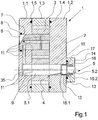
- Fig. 1 a first embodiment of the gear pump according to the invention is shown.
- the middle plate 1.3 has recesses for two intermeshing gears 3 and 4.
- the gear 3 is rotatably mounted on a fixed bearing shaft 6.
- the bearing shaft 6 is firmly connected to the housing plate 1.1 in a receiving bore 7.
- sealing ring 8 is arranged between the bearing shaft 6 and the housing plate 1.1 .
- a flushing system with a plurality of flushing channels 11 in the housing plates 1.1 and 1.2 and the shafts 5 and 6 is formed within the pump housing 1 to a from outside via to flush a closable inlet 35 supplied rinsing agent for flushing the gaps between the rotating and stationary components within the pump housing.
- a gear pump is for example from the EP 1 164 293 A2 known, so that at this point reference can be made to the description given there.
- a support housing 14 for receiving a support bearing of the drive shaft 5 is provided on the drive side of the gear pump.
- the support housing 14 is for this purpose fixedly connected to the pump housing 1, wherein concentric with the bearing bore 10, a sealing ring 17 between the support housing 14 and the pump housing 1 is arranged.
- a recess 16 is formed, which on the one hand allows penetration of the coupling portion 5.2 of the drive shaft 5 and on the other hand fixed a support ring 13 in the radial and axial direction to the drive side.
- the support ring 13 is for this purpose L-shaped and is located at a second diameter stage 15.2 of the drive shaft 5 at.
- the support ring 13 is preferably formed from a plastic and pressed firmly into the recess 16 of the support housing 13.
- the support ring 13 is held with an outer peripheral surface without play in an inner diameter of the stepped recess 16.
- the support ring 13 bears against the support housing 14 with an end face adjoining the outer peripheral surface.
- the opposite inner peripheral surface and the opposite end face form the stop surface for the drive shaft.
- the outside of the support housing 14 outstanding end of the coupling section 5.2 of the drive shaft 5 (not shown here) is used to connect a drive, preferably by means of a coupling.
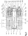
- Fig. 2 and Fig. 3 is shown a further embodiment of the gear pump according to the invention.
- the following description applies to both figures insofar as no explicit reference is made to one of the figures.
- Fig. 2 is the gear pump in a first sectional view of the gear pair and in Fig. 3 a second sectional view of the drive shaft orthogonal to the sectional view in Fig. 2 shown.
- the embodiment is in the construction of the gear pair of the gears 3 and 4 and the pump housing 1 is substantially identical to the previous embodiment, so that at this point substantially reference is made to the above description.
- the drive shaft 5 is on the bearing bushes 18.1 and 18.2 in the bearing blind hole 9 of the housing plate 1.1 and the bearing bore 10 of the housing plate 1.2 rotatably mounted. Between the housing plates 1.1 and 1.2, the driven gear 4 is attached to the bearing section 5.1 of the drive shaft 5 at the periphery.
- the housing plate 1.1, the center plate 1.3 and the housing plate 1.2 are pressure-tightly connected to each other, wherein on the housing plate 1.2 each have a pump inlet and a pump outlet (only shown in phantom) are formed, wherein the pump inlet and the pump outlet are arranged in a plane and therefore in Fig. 2 only indicated by the reference numeral 2.
- the coupling section 5.2 of the drive shaft 5 projects out of the pump housing 1.
- the coupling section 5.2 of the drive shaft 5 has in the end region a diameter step 15, on which a support ring 13 rests.
- the support ring 13 is L-shaped and is held in a recess 16 a support housing 14.
- the formation of the support ring 13 and the support housing 14 for receiving the support ring 13 are identical to the embodiment according to Fig. 1 executed so that reference is made to the aforementioned embodiments for further description.
- the support housing 14 is penetrated by the coupling section 5.2 of the drive shaft 5 and protrudes with a free coupling end 5.3 for connecting a drive from the support housing 14 out. Between the coupling end 5.3 and the diameter stage 15, a shaft seal 33 is disposed between the support housing 14 and the drive shaft 5.
- the support housing 14 is pressure-tightly connected via a seal housing 19 to the pump housing 1.
- a first sealing ring 17.1 is arranged concentrically to the bearing bore 10 and between the seal housing 19 and the support housing 14 in the second sealing ring 17.2 between the pump housing 1 and the seal housing 19.
- the seal housing 19 has a recess formed concentrically to the drive shaft 5 20, which serves to receive a arranged on the circumference of the drive shaft 5 stuffing box 21.
- the gland packing 21 is supported on the end facing the pump housing 1 end of the seal housing 19 directly on the housing plate 1.2. At the opposite end of the gland packing 21 in the seal housing 19, a pressure ring 22 is guided concentrically to the drive shaft 5 mov
- the pressure ring 22 is pressed by a plurality of compression springs 24.1 and 24.2 formed clamping means against the gland packing 21.
- a plurality of compression springs 24.1 and 24.2 held by movably guided holding cages 23.1 and 23.2 in receiving bores 25.1 and 25.2 of the seal housing 19.
- the holding cages 23.1 and 23.2 act with a circumferential collar 36 directly on a circumferential shoulder 37 which is formed on the pressure ring 22.
- the compression springs 24.1 and 24.2 are guided in spring receiving bores 27.1 and 27.2 of the support housing 14.
- the compression springs are 24.1 and 24.2 directly to an end face of the contact piston 26.1 and 26.2.
- On the opposite end face of the contact piston 26.1 and 26.2 each has a screw 28.1 and 28.2, by which the contact piston 26.1 and 26.2 can be adjusted to adjust a spring preload of the packing 21.
- the bias is applied to the gland packing 21 between the housing plate 1.2 and the support housing 14 by a total of two compression springs 24.1 and 24.2.
- the annular space 29 formed between the packing 21 and the shaft sealing ring 33 between the drive shaft 5 and the seal housing 19 and the support housing 14 by two channels 30.1 and 30.2 are each connected to an inlet 31 and an outlet 32.
- the inlet 31 and the outlet 32 are designed to be closable, so that in the operating state, a barrier liquid is introduced into the seal housing 19, through which the annular space 29 is filled.
- a solvent-containing fluid is used as the barrier liquid, in order to dissolve the paint particles possibly emerging through gap leakage within the annular space 29, so that hardening in the gap is prevented.
- the mobility of the pressure ring 22 is ensured.
- a flushing of the annular space 29 via the channels 30.1 and 30.2 and the inlet 31 of the outlet 32 can be performed in a simple manner during maintenance and replacement of the barrier liquid.
- This in Fig. 2 and 3 illustrated embodiment of the gear pump according to the invention is particularly suitable to carry out the metering of paint colors with high operating pressures.
- a return of the gear pump is set in a color change to initiate a color change.
- Higher operating pressures are usually achieved here, but due to the prestressed stuffing box packing, they can be safely withstood without the risk of leakage.
- Fig. 1 to 3 illustrated embodiments of the gear pump according to the invention are exemplary in construction and design of the individual components. It is essential here that an axial support takes place for the pressure forces acting on the drive shaft. This can in particular reduce the signs of wear on the driven tooth. In addition, the radial support of the drive shaft leads to increase the bearing life within the pump housing, in particular an externally acting transverse load on the drive shaft is reduced.
Landscapes
- Engineering & Computer Science (AREA)
- Mechanical Engineering (AREA)
- General Engineering & Computer Science (AREA)
- Rotary Pumps (AREA)
- Details And Applications Of Rotary Liquid Pumps (AREA)
Description
- Die Erfindung betrifft eine Zahnradpumpe zum dosierten Fördern von Farblacken gemäß dem Oberbegriff des Anspruch 1.
- Eine gattungsgemäße Zahnradpumpe ist aus der
EP 1 164 293 A2 bekannt. - Die bekannte Zahnradpumpe weist zwei ineinander kämmende Zahnräder auf, die innerhalb eines Pumpengehäuses drehbar gelagert sind. Eines der Zahnräder ist dabei am Umfang einer Antriebswelle gehalten, die in mehreren Lagerstellen innerhalb des Pumpengehäuses gelagert ist. Mit einem Kupplungsabschnitt ragt die Antriebswelle zur Anbindung eines Antriebes aus dem Pumpengehäuse heraus. Innerhalb des Pumpengehäuses ist ein Spülkanalsystem ausgebildet, durch welche eine Spülung der Zahnradpumpe mit einem Spülmittel möglich ist. Damit lassen sich bei Farbumstellungen die innerhalb des Pumpengehäuses angesammelten Farbreste schnell und einfach ausspülen.
Die bekannte Zahnradpumpe wird in Farbzerstäubungseinrichtungen zum Lackieren von Bauteilen beispielsweise von Fahrzeugteilen eingesetzt. Um komplexe Bauteile innerhalb einer Lackiereinrichtung zu behandeln, ist es bekannt, Lackierroboter einzusetzen, die an einem Roboterarm eine Zerstäubereinrichtung halten.
Ein derartiger Lackierroboter ist beispielsweise aus derEP 1 447 183 A1 bekannt. Hierbei müssen die an einem Roboterarm gehaltenen Lackierdüseneinrichtungen möglichst kompakt ausgebildet sein. Zudem wirken ständig wechselnde Beschleunigungskräfte auf die Einrichtung aufgrund der Bewegung des Roboterarmes ein. Um den Leitungsaufwand möglichst gering zu halten, ist es üblich, Lackierpumpen unmittelbar mit einer Zerstäubereinheit zu kombinieren, um eine Baueinheit zur Aufnahme in einem Roboterarm zu erhalten. Die bekannte Zahnradpumpe ist jedoch im Wesentlichen für einen stationären Einbauraum ausgelegt, an dem keine wesentlichen Belastungen aus dem Umfeld auf die Zahnradpumpe einwirken. - Ferner ist aus der
JP 07 080366 - Darüber hinaus zeigt die
WO-A1-99/40324 WO-A1-99/40324 - Es ist nun Aufgabe der Erfindung, eine Zahnradpumpe der eingangs genannten Art zu schaffen, die besonders zum dosierten Fördern von Farblacken an einem Lackierroboter geeignet ist.
- Ein weiteres Ziel der Erfindung liegt darin, eine Zahnradpumpe bereitzustellen, die auch bei hohen Betriebsdrücken Farblacke verschleißarm fördert.
- Die Aufgabe wird erfindungsgemäß durch eine Zahnradpumpe mit den Merkmalen nach Anspruch 1 gelöst.
- Vorteilhafte Weiterbildungen der Erfindung sind durch die Merkmale und Merkmalskombinationen der Unteransprüche definiert.
Die Erfindung zeichnet sich dadurch aus, dass sowohl innere Druckkräfte als auch die von außen auf die Antriebswelle einwirkenden Kräfte vorteilhaft außerhalb des Pumpengehäuses durch eine separate Stützlagerung abgefangen werden können. Hierzu ist an dem außerhalb des Pumpengehäuses ragenden Kupplungsabschnitt der Antriebswelle die Stützlagerung zur radialen und axialen Abstützung der Antriebswelle ausgebildet. Durch die axiale Abstützung der Antriebswelle lassen sich die an der Antriebswelle wirkenden Druckkräfte auffangen, so dass das an der Antriebswelle befestigte Zahnrad an den Stirnseiten im wesentlichen verschleißfrei zum Pumpengehäuse geführt werden kann. Damit erhöht sich die Betriebsdauer, da der Verschleiß an den Zahnrädern erheblich reduziert wird. Eine Erhöhung des Betriebsdruckes bleibt ohne Auswirkung auf den Verschleiß am Zahnrad, da die axiale Abstützung der Antriebswelle unabhängig von der Größe des Betriebsdruckes ist. Die radiale Abstützung der Antriebswelle außerhalb des Pumpengehäuses nimmt die von außen auf die Antriebswelle einwirkende Kräfte auf ohne wesentliche Auswirkung auf die Lagerstellen der Zahnräder innerhalb des Pumpengehäuses. - Zur Ausbildung des Stützlagers wird ein Stützring innerhalb eines Stützgehäuses angeordnet, wobei das Stützgehäuse fest mit dem Pumpengehäuse verbunden ist und in einer Ausnehmung von dem Kupplungsabschnitt der Antriebswelle durchdrungen ist. Der Stützring wird dabei zwischen einer Durchmesserstufe der Antriebswelle und dem Stützgehäuse angeordnet, wobei zur Befestigung des Stützringes gegenüber der Antriebswelle der Stützring mit dem Stützgehäuse fest verbunden ist.
Zur Ausbildung zweier Anschlagflächen für die axiale und radiale Abstützung ist der Stützring vorteilhaft durch einen L-förmigen Querschnitt ausgebildet, welcher mit einer äußeren Unfangsfläche und einer angrenzenden Stirnfläche an dem Stützgehäuse anliegt und welcher mit den gegenüber liegenden inneren Umfangsflächen und einer angrenzenden Stirnfläche an der Antriebswelle ansteht. - Zur Realisierung einer besonders kompakten Bauform ist gemäß einer vorteilhaften Weiterbildung der Erfindung zwischen dem Stützgehäuse und dem Pumpengehäuse ein Dichtungsgehäuse druckdicht angeordnet, welches in einer konzentrisch zur Antriebswelle ausgebildeten Ausnehmung von dem Kupplungsabschnitt der Antriebswelle durchdrungen ist und welches einen am Umfang der Antriebswelle angeordnetes Dichtungsmittel umschließt. Die das Pumpengehäuse bildenden Gehäuseplatten lassen sich somit allein auf die Lagerung der Zahnräder abstimmen. Das zur Abdichtung der Antriebswelle nach außen hin erforderliche Dichtungsmittel kann unabhängig von der Lagerung ausgebildet und ausgestaltet werden.
- Als Dichtungsmittel werden vorteilhaft eine Stopfbuchsenpackung und ein Spannmittel eingesetzt, das auf die Stopfbuchsenpackung einwirkt. Damit lässt sich eine Abdichtung gegenüber hohen Betriebsdrücken innerhalb des Pumpengehäuses realisieren. Insbesondere werden damit auch Rückförderungen des jeweiligen Farblackes möglich, um beispielsweise einen Farbwechsel einzuleiten. Hierzu lässt sich die Antriebswelle mit wechselndem Drehsinn antreiben.
- Als Spannmittel werden vorteilhaft mehrere Druckfedern zwischen der Stopfbuchsenpackung und dem Stützgehäuse gespannt.
- Dabei ist besonders vorteilhaft, dass jedem der Druckfedern innerhalb des Stützgehäuses ein Anlagekolben zugeordnet ist, welcher innerhalb einer Federaufnahmebohrung in Spannrichtung verstellbar ausgebildet ist. Somit lassen sich nach Ablauf bestimmter Betriebszeiten die an der Stopfbuchpackung wirkende Spannkräfte erhöhen bzw. regenerieren.
- Um mit fortschreitender Betriebsdauer aufgrund minimaler Leckagen Anlagerungen von Farblacken in Ringspalten außerhalb des Pumpengehäuses zu vermeiden, ist gemäß einer bevorzugten Weiterbildung der Erfindung innerhalb des Stützgehäuses ein Wellendichtring an dem Umfang der Antriebswelle angeordnet und in dem zwischen dem Dichtungsmittel und dem Wellendichtring ausgebildeten Ringraum am Umfang der Antriebswelle eine Sperrflüssigkeit gefüllt. Als Sperrflüssigkeit wird hierbei beispielsweise ein lösemittelhaltiges Fluid eingesetzt.
- Hierbei ist die Weiterbildung der Erfindung besonders vorteilhaft, bei welcher der Ringraum über separate Führungskanäle mit einem Einlaß und einem Auslaß verbunden ist, wobei der Einlaß und der Auslaß am Dichtungsgehäuse ausgebildet sind. Damit lassen sich die Spalten zwischen der Antriebswelle und den Gehäuseteilen nach Auswechselung des Sperrfluids vorteilhaft ausspülen.
- Um nach einem Farbewechsel die innerhalb des Pumpengehäuses enthaltenen Farbreste möglichst in kurzer Zeit und schnell ohne jegliche Demontagearbeiten entfernen zu können, ist ein Spülkanalsystem innerhalb des Pumpengehäuses ausgebildet, durch welches die zwischen den Zahnrädern, den Wellen und Pumpengehäuse gebildeten Spalte spülbar sind.
- Die erfindungsgemäße Zahnradpumpe wird nachfolgend anhand einiger Ausführungsbeispiele unter Hinweis auf die beigefügten Figuren näher erläutert.
- Es stellen dar:
- Fig. 1
- schematisch eine Querschnittsansicht eines ersten Ausführungsbeispiels der erfindungsgemäßen Zahnradpumpe
- Fig. 2 und Fig. 3
- schematisch mehrere Schnittansichten eines weiteren Ausführungsbeispiels der erfindungsgemäßen Zahnradpumpe
- In
Fig. 1 ist ein erstes Ausführungsbeispiel der erfindungsgemäßen Zahnradpumpe dargestellt. - Die Zahnradpumpe besteht aus einem Pumpengehäuse 1. Das Pumpengehäuse 1 ist mehrteilig aufgebaut und weist die Gehäuseplatten 1.1 und 1.2 sowie die zwischen den Gehäuseplatten 1.1 und 1.2 gehaltene Mittelplatte 1.3 auf. In den Stirnseiten der Gehäuseplatten 1.1 und 1.2 ist jeweils ein Dichtring 1.4 und 1.5 angeordnet, durch welchen die Spalte zwischen der Mittelplatte 1.3 und den Gehäuseplatten 1.1 und 1.2 nach außen hin abgedichtet sind.
- Die Mittelplatte 1.3 weist Aussparungen für zwei ineinander kämmende Zahnräder 3 und 4 auf. Das Zahnrad 3 ist drehbar an einer festen Lagerwelle 6 gelagert. Die Lagerwelle 6 ist hierzu in einer Aufnahmebohrung 7 fest mit der Gehäuseplatte 1.1 verbunden. Zwischen der Lagerwelle 6 und der Gehäuseplatte 1.1 ist eine in der Aufnahmebohrung 7 eingebrachter Dichtring 8 angeordnet.
- Das zweite Zahnrad 4 ist auf einer Antriebswelle 5 gepresst. Die Antriebswelle 5 ist mit einem freien Ende in einer Lagersackbohrung 9 an der Gehäusenplatte 1.1 gelagert, so dass sich zwischen der Gehäuseplatte 1.1 und der Antriebswelle 5 ein Lagerspalt ausbildet. Auf der gegenüberliegenden Seite des Zahnrades 4 ist die Antriebswelle 5 in der Gehäuseplatte 1.2 in eine durchgehende Lagerbohrung 10 drehbar gelagert. Zwischen der Antriebswelle 5 und der Gehäuseplatte 1.2 ist ein Dichtungsmittel 12 außerhalb der Lagerung vorgesehen, so dass ein freier Kupplungsabschnitt 5.2 der Antriebswelle 5 druckdicht nach außen zu einem Antrieb geführt ist. Hierzu ist an der Antriebswelle 5 eine erste Durchmesserstufe 15.1 innerhalb des Pumpengehäuses 1 ausgebildet. Der Lagerabschnitt 5.1 der Antriebswelle 5 ist dabei der innerhalb des Pumpengehäuses 1 gelagerte Teil der Antriebswelle 5. In der Gehäuseplatte 1.2 sind ein Pumpeneinlaß und ein Pumpenauslaß eingebracht, die kanalförmig in eine Einlasskammer bzw. in eine Auslasskammer (hier nicht dargestellt) geführt sind. Der Pumpeneinlaß und der Pumpenauslaß liegen in einer Ebene, so dass nur eine gestrichelte Darstellung in
Fig. 1 mit dem Bezugszeichen 2 eingetragen ist. - Neben den betriebsbedingten Einlaß- und Auslasskanälen ist innerhalb des Pumpengehäuses 1 ein Spülsystem mit mehreren Spülkanälen 11 in den Gehäuseplatten 1.1 und 1.2 sowie den Wellen 5 und 6 ausgebildet, um eine von außen über einen verschließbaren Zulauf 35 zugeführtes Spülmittel zur Spülung der Spalten zwischen den drehenden und stehenden Bauteilen innerhalb des Pumpengehäuses zu spülen. Eine derartige Zahnradpumpe ist beispielsweise aus der
EP 1 164 293 A2 bekannt, so dass an dieser Stelle Bezug zu der dort angegebenen Beschreibung genommen werden kann. - An dem Pumpengehäuse 1 ist auf der Antriebsseite der Zahnradpumpe ein Stützgehäuse 14 zur Aufnahme einer Stützlagerung der Antriebswelle 5 vorgesehen. Das Stützgehäuse 14 ist hierzu fest mit dem Pumpengehäuse 1 verbunden, wobei konzentrisch zur Lagerbohrung 10 ein Dichtring 17 zwischen dem Stützgehäuse 14 und dem Pumpengehäuse 1 angeordnet ist. Innerhalb des Stützgehäuses 14 ist eine Ausnehmung 16 ausgebildet, die einerseits ein Durchdringen des Kupplungsabschnittes 5.2 der Antriebswelle 5 ermöglicht und andererseits einen Stützring 13 in radialer und in axialer Richtung zur Antriebsseite hin fixiert. Der Stützring 13 ist hierzu L-förmig ausgebildet und liegt an einer zweiten Durchmesserstufe 15.2 der Antriebswelle 5 an. Der Stützring 13 ist vorzugsweise aus einem Kunststoff gebildet und fest in die Ausnehmung 16 des Stützgehäuses 13 eingepreßt. Hierzu ist der Stützring 13 mit einer äußeren Umfangfläche ohne spiel in einem Innendurchmesser der gestuften Ausnehmung 16 gehalten. Dabei liegt der Stützring 13 mit einer zur äußeren Umfangsfläche angrenzenden Stirnfläche an dem Stützgehäuse 14 an. Die gegenüberliegende innere Umfangsfläche sowie die gegenüberliegende Stirnfläche bilden die Anschlagsfläche für die Antriebswelle.
- Das außerhalb des Stützgehäuses 14 herausragende Ende des Kupplungsabschnittes 5.2 der Antriebswelle 5 (hier nicht dargestellt) dient zur Anbindung eines Antriebes vorzugsweise mittels einer Kupplung.
- Im Betriebszustand wird ein über den Pumpeneinlaß zugeführter Farblack durch Drehung der Zahnräder 3 und 4 zum Pumpenauslaß gefördert und einem unmittelbar angeschlossenen Zerstäubungssystem einer Lackiereinrichtung zugeführt. Dabei wird die Antriebswelle 5 aufgrund der Druckwirkung an dem freien Stirnende des Lagerabschnittes 5.1 über den Stützring 13 gegen das Stützgehäuse 14 gedrückt. Durch entsprechende Auslegung der Spalten und Spiele wird verhindert, dass das Zahnrad 4 mit seiner Stirnfläche gegen die Gehäuseplatte 1.2 gedrückt wird. Zudem werden die von außen über den Kupplungsabschnitt 5.2 quer gerichteten Kräfte an der Antriebswelle 5 über den Stützring 13 und dem Stützgehäuse 14 aufgefangen. Eine sich bis in die Lagerung des Pumpengehäuses 1 fortpflanzende Verformung oder Biegung der Antriebswelle 5 wird vorteilhaft vermieden. Somit ist das in
Fig. 1 dargestellte Ausführungsbeispiel besonders geeignet, um an einem Lackierroboter verwendet zu werden. Es ist jedoch auch möglich, derartige Zahnradpumpen im stationären Einsatz zu verwenden, um beispielsweise sehr hohe Betriebslaufzeiten zur Förderung von besonders abrasiven Farblacken bei hohen Betriebsdrücken zu ermöglichen. - In
Fig. 2 undFig. 3 ist ein weiteres Ausführungsbeispiel der erfindungsgemäßen Zahnradpumpe dargestellt. Die nachfolgende Beschreibung gilt für beide Figuren insoweit kein ausdrücklicher Bezug zu einer der Figuren gemacht ist. InFig. 2 ist die Zahnradpumpe in einer ersten Schnittansicht der Zahnradpaarung und inFig. 3 eine zweite Schnittansicht der Antriebswelle orthogonal zu der Schnittansicht inFig. 2 dargestellt. - Das Ausführungsbeispiel ist im Aufbau der Zahnradpaarung der Zahnräder 3 und 4 sowie das Pumpengehäuses 1 im wesentlichen identisch zu dem vorhergehenden Ausführungsbeispiel, so dass an dieser Stelle im wesentlichen Bezug zu der vorgenannten Beschreibung genommen wird.
- Die Antriebswelle 5 ist über die Lagerbuchsen 18.1 und 18.2 in der Lagersacklochbohrung 9 der Gehäuseplatte 1.1 und der Lagerbohrung 10 der Gehäuseplatte 1.2 drehbar gelagert. Zwischen den Gehäuseplatten 1.1 und 1.2 ist an dem Lagerabschnitt 5.1 der Antriebswelle 5 das getriebene Zahnrad 4 am Umfang befestigt. Die Gehäuseplatte 1.1, die Mittelplatte 1.3 und die Gehäuseplatte 1.2 sind druckdicht miteinander verbunden, wobei an der Gehäuseplatte 1.2 jeweils ein Pumpeneinlaß und ein Pumpenauslaß (hier nur gestrichelt dargestellt) ausgebildet sind, wobei der Pumpeneinlaß und der Pumpenauslaß in einer Ebene angeordnet sind und daher in
Fig. 2 nur mit dem Bezugszeichen 2 gekennzeichnet. - An der Antriebsseite des Pumpengehäuses 1 ragt der Kupplungsabschnitt 5.2 der Antriebswelle 5 aus dem Pumpengehäuse 1 heraus. Der Kupplungsabschnitt 5.2 der Antriebswelle 5 weist im Endbereich eine Durchmesserstufe 15 auf, an welcher ein Stützring 13 anliegt. Der Stützring 13 ist L-förmig ausgebildet und wird in einer Ausnehmung 16 eine Stützgehäuses 14 gehalten.
- Die Ausbildung des Stützringes 13 und des Stützgehäuses 14 zur Aufnahme des Stützringes 13 sind identisch zu dem Ausführungsbeispiel nach
Fig. 1 ausgeführt, so dass zur weiteren Beschreibung auf vorgenannte Ausführungsbeispiele Bezug genommen wird. - Das Stützgehäuse 14 wird von dem Kupplungsabschnitt 5.2 der Antriebswelle 5 durchdrungen und ragt mit einem freien Kupplungsende 5.3 zur Anbindung eines Antriebs aus dem Stützgehäuse 14 heraus. Zwischen dem Kupplungsende 5.3 und der Durchmesserstufe 15 ist zwischen dem Stützgehäuse 14 und der Antriebswelle 5 ein Wellendichtring 33 angeordnet. Das Stützgehäuse 14 ist druckdicht über ein Dichtungsgehäuse 19 mit dem Pumpengehäuse 1 fest verbunden. Hierzu ist zwischen dem Pumpengehäuse 1 und dem Dichtungsgehäuse 19 ein erster Dichtring 17.1 konzentrisch zur Lagerbohrung 10 und zwischen dem Dichtungsgehäuse 19 und dem Stützgehäuse 14 im zweiten Dichtring 17.2 angeordnet. Das Dichtungsgehäuse 19 weist eine konzentrisch zur Antriebswelle 5 ausgebildete Ausnehmung 20 auf, die zur Aufnahme einer am Umfang der Antriebswelle 5 angeordnete Stopfbuchsenpackung 21 dient. Die Stopfbuchsenpackung 21 stützt sich an der zum Pumpengehäuse 1 gewandten Ende des Dichtungsgehäuses 19 unmittelbar an der Gehäuseplatte 1.2 ab. An dem gegenüberliegenden Ende der Stopfbuchsenpackung 21 ist in dem Dichtungsgehäuse 19 ein Druckring 22 konzentrisch zur Antriebswelle 5 beweglich geführt.
- Wie in
Fig. 3 dargestellt ist, wird der Druckring 22 durch ein aus mehreren Druck-Druckfedern 24.1 und 24.2 gebildetes Spannmittel gegen die Stopfbuchsenpackung 21 gedrückt. Hierzu sind mehrere Druckfedern 24.1 und 24.2 durch beweglich geführte Haltekäfige 23.1 und 23.2 in Aufnahmebohrungen 25.1 und 25.2 des Dichtungsgehäuses 19 gehalten. Die Haltekäfige 23.1 und 23.2 wirken mit einem umlaufenden Kragen 36 unmittelbar auf einen umlaufenden Absatz 37, der an dem Druckring 22 ausgebildet ist. Gegenüberliegend zu den beweglich geführten Haltekäfigen 23.1 und 23.2 werden die Druckfedern 24.1 und 24.2 in Federaufnahmebohrungen 27.1 und 27.2 des Stützgehäuses 14 geführt. Am Ende der Aufnahmebohrungen 27.1 und 27.2 sind Anlagekolben 26.1 und 26.2 angeordnet, die druckdicht in den Federaufnahmebohrungen 27.1 und 27.2 führbar sind. Hierbei liegen die Druckfedern 24.1 und 24.2 unmittelbar an einer Stirnseite der Anlagekolben 26.1 und 26.2 an. Auf der gegenüberliegenden Stirnseite der Anlagekolben 26.1 und 26.2 wirkt jeweils eine Stellschraube 28.1 und 28.2, durch welche der Anlagekolben 26.1 und 26.2 zur Einstellung einer Federvorspannung der Stopfbuchsenpackung 21 verstellt werden kann. - Bei der in
Fig. 3 dargestellten Situation wird die Vorspannung an der Stopfbuchsenpackung 21 zwischen der Gehäuseplatte 1.2 und dem Stützgehäuse 14 durch insgesamt zwei Druckfedern 24.1 und 24.2 aufgebracht. Um eine gleichmäßige Vorspannung zu erhalten, lassen sich vorteilhaft mehrere Druckfedern in dem Dichtungsgehäuse 19 in gleicher Art und Weise ausbilden, so dass beispielsweise die Stopfbuchsenpackung 21 durch vier, fünf oder sechs Druckfedern verspannt werden kann. - Aus der Schnittdarstellung in
Fig. 2 geht des weiteren hervor, dass der zwischen der Stopfbuchsenpackung 21 und dem Wellendichtring 33 gebildete Ringraum 29 zwischen der Antriebswelle 5 und dem Dichtungsgehäuse 19 sowie dem Stützgehäuse 14 durch zwei Kanäle 30.1 und 30.2 jeweils mit einem Einlaß 31 und einem Auslaß 32 verbunden sind. Der Einlaß 31 und der Auslaß 32 sind verschließbar ausgebildet, so dass im Betriebszustand eine Sperrflüssigkeit in das Dichtungsgehäuse 19 eingeleitet wird, durch welchen der Ringraum 29 gefüllt ist. Als Sperrflüssigkeit wird dabei vorzugsweise ein lösemittelhaltiges Fluid eingesetzt, um die möglicherweise durch Spaltleckage austretenden Lackpartikel innerhalb des Ringraumes 29 zu lösen, so dass Verhärtungen in den Spalt verhindert werden. Insbesondere unter Berücksichtigung einer Nachstellung der Federspannung bleibt die Beweglichkeit des Druckrings 22 gewährleistet. Zudem lässt sich bei einer Wartung und Austausch der Sperrflüssigkeit eine Spülung des Ringraumes 29 über die Kanäle 30.1 und 30.2 und dem Einlaß 31 von Auslaß 32 auf einfache Art und Weise ausführen. - Das in
Fig. 2 und3 dargestellte Ausführungsbeispiel der erfindungsgemäßen Zahnradpumpe ist besonders geeignet, um die Dosierung von Lackfarben mit hohen Betriebsdrücken auszuführen. Insbesondere bei der Verwendung derartiger Zahnradpumpen in Lackierroboter wird bei einem Farbwechsel eine Rückförderung von der Zahnradpumpe eingestellt, um einen Farbewechsel einzuleiten. Hierbei werden üblicherweise höhere Betriebsdrücke erreicht, die jedoch aufgrund der vorgespannten Stopfbuchsenpackung ohne Gefahr einer Leckage sicher ertragen werden können. - Die in den
Fig. 1 bis 3 dargestellten Ausführungsbeispiele der erfindungsgemäßen Zahnradpumpe sind in Aufbau und Ausbildung der einzelnen Bauteile beispielhaft. Wesentlich hierbei ist, dass für die an der Antriebswelle wirkenden Druckkräfte eine axiale Abstützung erfolgt. Damit lassen sich insbesondere die Verschleißerscheinungen an dem getriebenen Zahn vermindern. Zudem führt die radiale Abstützung der Antriebswelle zur Erhöhung der Lagerlebensdauer innerhalb des Pumpengehäuses, wobei insbesondere eine von außen einwirkende Querbelastung an der Antriebswelle vermindert wird. -
- 1
- Pumpengehäuse
- 1.1
- Gehäuseplatte
- 1.2
- Gehäuseplatte
- 1.3
- Mittelplatte
- 1.4
- Dichtring
- 1.5
- Dichtring
- 2
- Pumpeneinlaß / -auslaß
- 3
- Zahnrad (mitlaufend)
- 4
- Zahnrad (getrieben)
- 5
- Antriebswelle
- 5.1
- Lagerabschnitt
- 5.2
- Kupplungsabschnitt
- 5.3
- Kupplungsende
- 6
- Lagerwelle
- 7
- Aufnahmebohrung
- 8
- Dichtring
- 9
- Lagersackbohrung
- 10
- Lagerbohrung
- 11.1 ...
- Spülkanal
- 12
- Dichtungsmittel
- 13
- Stützring
- 14
- Stützgehäuse
- 15, 15.1, 15.2
- Durchmesserstufe
- 16
- Ausnehmung
- 17, 17.1, 17.2
- Dichtring
- 18.1, 18.2
- Lagerbuchse
- 19
- Dichtungsgehäuse
- 20
- Ausnehmung
- 21
- Stopfbuchsenpackung
- 22
- Druckring
- 23.1, 23.2
- Haltekäfig
- 24.1, 24.2
- Druckfeder
- 25.1, 25.2
- Sackbohrung
- 26.1, 26.2
- Anlagekolben
- 27.1, 27.2
- Federaufnahmebohrung
- 28.1, 28.2
- Stellschraube
- 29
- Ringraum
- 30.1, 30.2
- Kanal
- 31
- Einlaß
- 32
- Auslaß
- 33
- Wellendichtung
- 34
- Dichtring
- 35
- Zulauf
- 36
- Kragen
- 37
- Absatz
Claims (10)
- Zahnradpumpe zum dosierten Fördern von Farblacken, insbesondere zur Verwendung an einem Lackierroboter, mit zwei ineinander kämmenden Zahnrädern (3, 4), welche durch eine angetriebene Antriebswelle (5) und eine feststehende Lagerwelle (6) innerhalb eines Pumpengehäuses (1) drehbar gelagert sind, wobei die Antriebswelle (5) mit einem Lagerabschnitt (5.1) mehrmals im Pumpengehäuse (1) gelagert ist und mit einem Kupplungsabschnitt (5.2) außerhalb des Pumpengehäuses (1) mit einem Antrieb verbindbar ist,
wobei an dem außerhalb des Pumpengehäuses (1) ragenden Kupplungsabschnitt (5.2) eine Stützlagerung (13, 14) zur Abstützung der Antriebswelle (5) ausgebildet ist, dadurch gekennzeichnet, dass
die Stützlagerung (13, 14) zur radialen und axialen Abstützung
der Antriebswelle (5) ausgebildet ist, und dass die Stützlagerung durch einen Stützring (13) gebildet ist, welcher zwischen einer Durchmesserstufe (15) der Antriebswelle (5) und einem Stützgehäuse (14) angeordnet ist, wobei das Stützgehäuse (14) fest mit dem Pumpengehäuse (1) verbunden ist und in einer Ausnehmung (16) von dem Kupplungsabschnitt (5.2) der Antriebswelle (5) durchdrungen ist. - Zahnradpumpe nach Anspruch 1,
dadurch gekennzeichnet, dass
der Stützring (13) einen L-förmigen Querschnitt mit einer äußeren Umfangsfläche und einer angrenzenden Stirnfläche aufweist, die an dem Stützgehäuse (14) befestigt sind, und dass der Stützring (13) mit der gegenüberliegenden inneren Umfangsfläche und einer angrenzenden Stirnfläche an der Antriebswelle (5) anliegt. - Zahnradpumpe nach einem der Ansprüche 1 oder 2,
dadurch gekennzeichnet, dass
zwischen dem Stützgehäuse (14) und dem Pumpengehäuse (1) ein Dichtungsgehäuse (19) druckdicht angeordnet ist, welches in einer konzentrisch zur Antriebswelle (5) ausgebildeten Ausnehmung (20) von dem Kupplungsabschnitt (5.2) der Antriebswelle (5) durchdrungen ist und welches ein am Umfang der Antriebswelle (5) angeordnetes Dichtungsmittel (21) umschliesst. - Zahnradpumpe nach Anspruch 3,
dadurch gekennzeichnet, dass
das Dichtungsmittel durch eine Stopfbuchsenpackung (21) und einem auf die Stopfbuchsenpackung (21) einwirkendes Spannmittel (24.1, 24.2) gebildet ist. - Zahnradpumpe nach Anspruch 4,
dadurch gekennzeichnet, dass
das Spannmittel durch mehrere Druckfedern (24.1, 24.2) gebildet ist, welche zwischen der Stopfbuchsenpackung (21) und dem Stützgehäuse (14) gespannt sind. - Zahnradpumpe nach Anspruch 5,
dadurch gekennzeichnet, dass
zur Aufnahme der Druckfedern (24.1, 24.2) jeweils ein zylinderförmiger Haltekäfig (23.1, 23.2) vorgesehen ist, welcher in einer stirnseitigen Aufnahmebohrung (25.1, 25.2) des Dichtungsgehäuses (19) beweglich geführt ist und welcher sich mit einem inneren Kragen (36) an einem Druckring (22) der Stopfbuchsenpackung (21) abstützt. - Zahnradpumpe nach Anspruch 5 oder 6,
dadurch gekennzeichnet, dass
in dem Stützgehäuse (14) jedem der Druckfedern (24.1, 24.2) ein Anlagekolben (26.1, 26.2) zugeordnet ist, welche innerhalb einer Federaufnahmebohrung (27.1, 27.2) in Spannrichtung verstellbar ausgebildet ist. - Zahnradpumpe nach einem der Ansprüche 3 bis 7,
dadurch gekennzeichnet, dass
innerhalb des Stützgehäuses (14) ein Wellendichtring (33) an dem Umfang der Antriebswelle (5) angeordnet ist und dass der sich zwischen dem Dichtungsmittel (21) und dem Wellendichtring (33) ausgebildet Ringraum (29) am Umfang der Antriebswelle (5) mit einer Sperrflüssigkeit gefüllt ist. - Zahnradpumpe nach Anspruch 8,
dadurch gekennzeichnet, dass
der Ringraum (29) über separate Kanäle (30.1, 30.2) mit einem Einlass (31) und einem Auslass (32) verbunden ist und dass der Einlass (31) und der Auslass (32) am Dichtungsgehäuse (19) ausgebildet sind. - Zahnradpumpe nach einem der vorgenannten Ansprüche,
dadurch gekennzeichnet, dass
innerhalb des Pumpengehäuses (1) ein Spülkanalsystem (11) zum Spülen von Spalten zwischen den Zahnrädern (3, 4), den Wellen (5, 6) und dem Pumpengehäuse (1) vor einem Farbwechsel ausgebildet ist.
Applications Claiming Priority (1)
| Application Number | Priority Date | Filing Date | Title |
|---|---|---|---|
| DE102004052558A DE102004052558A1 (de) | 2004-10-29 | 2004-10-29 | Zahnradpumpe |
Publications (2)
| Publication Number | Publication Date |
|---|---|
| EP1653083A1 EP1653083A1 (de) | 2006-05-03 |
| EP1653083B1 true EP1653083B1 (de) | 2017-09-06 |
Family
ID=35601707
Family Applications (1)
| Application Number | Title | Priority Date | Filing Date |
|---|---|---|---|
| EP05022993.9A Expired - Lifetime EP1653083B1 (de) | 2004-10-29 | 2005-10-21 | Zahnradpumpe mit einer radialen und axialen Stützlagerung |
Country Status (7)
| Country | Link |
|---|---|
| US (1) | US7495575B2 (de) |
| EP (1) | EP1653083B1 (de) |
| CN (1) | CN100513788C (de) |
| CA (1) | CA2524413C (de) |
| DE (1) | DE102004052558A1 (de) |
| ES (1) | ES2651344T3 (de) |
| MX (1) | MXPA05011561A (de) |
Families Citing this family (11)
| Publication number | Priority date | Publication date | Assignee | Title |
|---|---|---|---|---|
| US7740458B2 (en) * | 2006-06-08 | 2010-06-22 | Adapt-A-Case, Llc | Transfer case pump bracket |
| EP1892418A3 (de) * | 2006-08-12 | 2014-08-27 | INDUSTRA Industrieanlagen - Maschinen und Teile GmbH | Zahnradmaschine |
| EP2122175B1 (de) * | 2007-03-20 | 2015-07-29 | Oerlikon Textile GmbH & Co. KG | Zahnradpumpe |
| DE102009019419B4 (de) * | 2009-04-29 | 2016-01-14 | Schwäbische Hüttenwerke Automotive GmbH | Umlaufverdrängermaschine mit vereinfachter Lagerachse oder -welle |
| DE102010012653A1 (de) * | 2010-03-25 | 2011-09-29 | Oerlikon Textile Gmbh & Co. Kg | Zahnradpumpe |
| CN106733501A (zh) * | 2017-02-24 | 2017-05-31 | 上海牛盟科技有限公司 | 单组分液体胶精密供胶装置 |
| GB2571969B (en) * | 2018-03-14 | 2020-10-07 | Edwards Tech Vacuum Engineering Qingdao Co Ltd | A liquid ring pump manifold with an integrated spray nozzle |
| GB2571972B (en) * | 2018-03-14 | 2021-01-20 | Edwards Tech Vacuum Engineering Qingdao Co Ltd | Method and apparatus related to servicing of liquid ring pumps |
| WO2021244917A1 (de) | 2020-05-30 | 2021-12-09 | Oerlikon Textile Gmbh & Co. Kg | Zahnradpumpe zum dosierten fördern von farblacken |
| CN112879202B (zh) * | 2020-12-30 | 2022-04-12 | 天津天发总厂机电设备有限公司 | 一种具有升降调向功能的水轮发电机 |
| CN116066354A (zh) * | 2021-11-02 | 2023-05-05 | 上海发那科机器人有限公司 | 一种集成快速内部清洗功能的齿轮泵 |
Citations (5)
| Publication number | Priority date | Publication date | Assignee | Title |
|---|---|---|---|---|
| US3133506A (en) * | 1961-08-15 | 1964-05-19 | Luciani Louis | Gear pump having internal bearings and seals |
| US3309997A (en) * | 1964-07-31 | 1967-03-21 | Shimadzu Corp | Gear pump or motor |
| DE9011156U1 (de) * | 1990-07-28 | 1990-11-15 | Schneider, Friedhelm, 5226 Reichshof | Zahnradpumpe für hochviskose Flüssigkeiten |
| DE9215104U1 (de) * | 1992-10-23 | 1993-01-07 | Maag Pump Systems AG, Zürich | Zahnradpumpe |
| WO1999040324A1 (de) * | 1998-02-03 | 1999-08-12 | Hartmut Hasse | Abdichtungssystem für zahnradpumpen für hochviskosen kautschuk, polymere stoffe und sonstige zu fördernde produkte |
Family Cites Families (11)
| Publication number | Priority date | Publication date | Assignee | Title |
|---|---|---|---|---|
| US3309998A (en) * | 1965-08-09 | 1967-03-21 | Sundstrand Corp | Gear pump with heat control |
| US4534717A (en) * | 1981-05-01 | 1985-08-13 | Ford Motor Company | Flushable metering pump |
| CH684954A5 (de) * | 1991-02-27 | 1995-02-15 | Maag Pump Systems Ag | Zahnradpumpe. |
| JP3170118B2 (ja) | 1993-09-16 | 2001-05-28 | エービービー株式会社 | 塗装用ギヤポンプ装置 |
| JPH11247767A (ja) * | 1997-12-23 | 1999-09-14 | Maag Pump Syst Textron Ag | 歯車ポンプの軸を位置決めするための方法および歯車ポンプ |
| US6171089B1 (en) * | 1998-05-12 | 2001-01-09 | Parker-Hannifin Corporation | External gear pump with drive gear seal |
| JP3988258B2 (ja) * | 1998-06-25 | 2007-10-10 | 東レ株式会社 | ギヤポンプ |
| US6158997A (en) * | 1999-06-30 | 2000-12-12 | Fluid Management | Gear pump |
| AU766733B2 (en) * | 1999-08-27 | 2003-10-23 | James B. Tieben | Pump |
| DE50110984D1 (de) * | 2000-06-14 | 2006-10-26 | Saurer Gmbh & Co Kg | Abspülbare Zahnradpumpe |
| DE10304652A1 (de) | 2003-02-05 | 2004-08-19 | Dürr Systems GmbH | Roboter |
-
2004
- 2004-10-29 DE DE102004052558A patent/DE102004052558A1/de not_active Withdrawn
-
2005
- 2005-10-21 EP EP05022993.9A patent/EP1653083B1/de not_active Expired - Lifetime
- 2005-10-21 ES ES05022993.9T patent/ES2651344T3/es not_active Expired - Lifetime
- 2005-10-26 CA CA2524413A patent/CA2524413C/en not_active Expired - Lifetime
- 2005-10-27 MX MXPA05011561A patent/MXPA05011561A/es active IP Right Grant
- 2005-10-28 CN CNB200510116094XA patent/CN100513788C/zh not_active Expired - Lifetime
- 2005-10-31 US US11/263,358 patent/US7495575B2/en active Active
Patent Citations (5)
| Publication number | Priority date | Publication date | Assignee | Title |
|---|---|---|---|---|
| US3133506A (en) * | 1961-08-15 | 1964-05-19 | Luciani Louis | Gear pump having internal bearings and seals |
| US3309997A (en) * | 1964-07-31 | 1967-03-21 | Shimadzu Corp | Gear pump or motor |
| DE9011156U1 (de) * | 1990-07-28 | 1990-11-15 | Schneider, Friedhelm, 5226 Reichshof | Zahnradpumpe für hochviskose Flüssigkeiten |
| DE9215104U1 (de) * | 1992-10-23 | 1993-01-07 | Maag Pump Systems AG, Zürich | Zahnradpumpe |
| WO1999040324A1 (de) * | 1998-02-03 | 1999-08-12 | Hartmut Hasse | Abdichtungssystem für zahnradpumpen für hochviskosen kautschuk, polymere stoffe und sonstige zu fördernde produkte |
Also Published As
| Publication number | Publication date |
|---|---|
| US7495575B2 (en) | 2009-02-24 |
| EP1653083A1 (de) | 2006-05-03 |
| US20060120856A1 (en) | 2006-06-08 |
| CN1769707A (zh) | 2006-05-10 |
| MXPA05011561A (es) | 2006-07-20 |
| CA2524413C (en) | 2012-10-09 |
| CN100513788C (zh) | 2009-07-15 |
| CA2524413A1 (en) | 2006-04-29 |
| ES2651344T3 (es) | 2018-01-25 |
| DE102004052558A1 (de) | 2006-05-04 |
Similar Documents
| Publication | Publication Date | Title |
|---|---|---|
| EP2122175B1 (de) | Zahnradpumpe | |
| EP2406497B1 (de) | Hydraulische zahnradmaschine | |
| EP2140142B1 (de) | Zahnradpumpe | |
| EP1429054A2 (de) | Planetengetriebe | |
| EP1653083A1 (de) | Zahnradpumpe mit einer radialen und axialen Stützlagerung | |
| EP2406496A2 (de) | Hydraulische zahnradmaschine | |
| DE2825616C2 (de) | Lager- und Dichtungsanordnung an den Wellen einer Zahnradpumpe | |
| EP2550456B1 (de) | Zahnradpumpe | |
| DE202006008288U1 (de) | Lageranordnung und Zumessventil hierfür | |
| DE102020134056A1 (de) | Drehkolbenpumpe | |
| EP1090226A1 (de) | Doppelpumpen-aggregat | |
| EP1164293B1 (de) | Abspülbare Zahnradpumpe | |
| DE2026303B2 (de) | Mit druckgas beschicktes querlager | |
| DE4202466A1 (de) | Hydraulischer motor | |
| WO2022207561A1 (de) | Innenzahnradfluidmaschine sowie verfahren zum herstellen einer innenzahnradfluidmaschine | |
| DE102018221146A1 (de) | Radialpumpe mit einem Außenläufer-Rotor zur Förderung eines Fluides aus einer Axialrichtung in eine Radialrichtung oder umgekehrt | |
| DE10317421A1 (de) | Planetengetriebe | |
| DE102013202917A1 (de) | Zahnradmaschine mit erhöhter Partikelrobustheit | |
| DE102010064130A1 (de) | Axialscheibe und Zahnradpumpe mit Axialscheibe | |
| DE102006013111A1 (de) | Zahnradpumpe | |
| DE1293599B (de) | Zahnradpumpe | |
| DE10110668B4 (de) | Kurvennuttrieb | |
| DE102017117689A1 (de) | Umlaufrädergetriebe | |
| EP1148006A1 (de) | Kettenrolle einer Transportkette | |
| DE102010009668A1 (de) | Zahnradpumpe |
Legal Events
| Date | Code | Title | Description |
|---|---|---|---|
| PUAI | Public reference made under article 153(3) epc to a published international application that has entered the european phase |
Free format text: ORIGINAL CODE: 0009012 |
|
| AK | Designated contracting states |
Kind code of ref document: A1 Designated state(s): AT BE BG CH CY CZ DE DK EE ES FI FR GB GR HU IE IS IT LI LT LU LV MC NL PL PT RO SE SI SK TR |
|
| AX | Request for extension of the european patent |
Extension state: AL BA HR MK YU |
|
| 17P | Request for examination filed |
Effective date: 20060915 |
|
| 17Q | First examination report despatched |
Effective date: 20061115 |
|
| AKX | Designation fees paid |
Designated state(s): AT BE BG CH CY CZ DE DK EE ES FI FR GB GR HU IE IS IT LI LT LU LV MC NL PL PT RO SE SI SK TR |
|
| RAP1 | Party data changed (applicant data changed or rights of an application transferred) |
Owner name: DUERR SYSTEMS GMBH Owner name: OERLIKON TEXTILE GMBH & CO. KG |
|
| RAP1 | Party data changed (applicant data changed or rights of an application transferred) |
Owner name: OERLIKON TEXTILE GMBH & CO. KG Owner name: DUERR SYSTEMS GMBH |
|
| REG | Reference to a national code |
Ref country code: DE Ref legal event code: R079 Ref document number: 502005015698 Country of ref document: DE Free format text: PREVIOUS MAIN CLASS: F04C0013000000 Ipc: F04C0002180000 |
|
| GRAP | Despatch of communication of intention to grant a patent |
Free format text: ORIGINAL CODE: EPIDOSNIGR1 |
|
| RIC1 | Information provided on ipc code assigned before grant |
Ipc: F04C 15/00 20060101ALI20170330BHEP Ipc: F04C 13/00 20060101ALI20170330BHEP Ipc: F04C 2/18 20060101AFI20170330BHEP Ipc: F01C 21/02 20060101ALI20170330BHEP |
|
| INTG | Intention to grant announced |
Effective date: 20170420 |
|
| GRAS | Grant fee paid |
Free format text: ORIGINAL CODE: EPIDOSNIGR3 |
|
| GRAA | (expected) grant |
Free format text: ORIGINAL CODE: 0009210 |
|
| AK | Designated contracting states |
Kind code of ref document: B1 Designated state(s): AT BE BG CH CY CZ DE DK EE ES FI FR GB GR HU IE IS IT LI LT LU LV MC NL PL PT RO SE SI SK TR |
|
| REG | Reference to a national code |
Ref country code: GB Ref legal event code: FG4D Free format text: NOT ENGLISH |
|
| REG | Reference to a national code |
Ref country code: CH Ref legal event code: EP Ref country code: AT Ref legal event code: REF Ref document number: 926206 Country of ref document: AT Kind code of ref document: T Effective date: 20170915 |
|
| REG | Reference to a national code |
Ref country code: IE Ref legal event code: FG4D Free format text: LANGUAGE OF EP DOCUMENT: GERMAN |
|
| REG | Reference to a national code |
Ref country code: DE Ref legal event code: R096 Ref document number: 502005015698 Country of ref document: DE |
|
| REG | Reference to a national code |
Ref country code: FR Ref legal event code: PLFP Year of fee payment: 13 |
|
| REG | Reference to a national code |
Ref country code: SE Ref legal event code: TRGR |
|
| REG | Reference to a national code |
Ref country code: NL Ref legal event code: FP |
|
| REG | Reference to a national code |
Ref country code: ES Ref legal event code: FG2A Ref document number: 2651344 Country of ref document: ES Kind code of ref document: T3 Effective date: 20180125 Ref country code: LT Ref legal event code: MG4D |
|
| PG25 | Lapsed in a contracting state [announced via postgrant information from national office to epo] |
Ref country code: LT Free format text: LAPSE BECAUSE OF FAILURE TO SUBMIT A TRANSLATION OF THE DESCRIPTION OR TO PAY THE FEE WITHIN THE PRESCRIBED TIME-LIMIT Effective date: 20170906 Ref country code: FI Free format text: LAPSE BECAUSE OF FAILURE TO SUBMIT A TRANSLATION OF THE DESCRIPTION OR TO PAY THE FEE WITHIN THE PRESCRIBED TIME-LIMIT Effective date: 20170906 |
|
| PG25 | Lapsed in a contracting state [announced via postgrant information from national office to epo] |
Ref country code: BG Free format text: LAPSE BECAUSE OF FAILURE TO SUBMIT A TRANSLATION OF THE DESCRIPTION OR TO PAY THE FEE WITHIN THE PRESCRIBED TIME-LIMIT Effective date: 20171206 Ref country code: GR Free format text: LAPSE BECAUSE OF FAILURE TO SUBMIT A TRANSLATION OF THE DESCRIPTION OR TO PAY THE FEE WITHIN THE PRESCRIBED TIME-LIMIT Effective date: 20171207 Ref country code: LV Free format text: LAPSE BECAUSE OF FAILURE TO SUBMIT A TRANSLATION OF THE DESCRIPTION OR TO PAY THE FEE WITHIN THE PRESCRIBED TIME-LIMIT Effective date: 20170906 |
|
| PG25 | Lapsed in a contracting state [announced via postgrant information from national office to epo] |
Ref country code: CZ Free format text: LAPSE BECAUSE OF FAILURE TO SUBMIT A TRANSLATION OF THE DESCRIPTION OR TO PAY THE FEE WITHIN THE PRESCRIBED TIME-LIMIT Effective date: 20170906 Ref country code: RO Free format text: LAPSE BECAUSE OF FAILURE TO SUBMIT A TRANSLATION OF THE DESCRIPTION OR TO PAY THE FEE WITHIN THE PRESCRIBED TIME-LIMIT Effective date: 20170906 Ref country code: PL Free format text: LAPSE BECAUSE OF FAILURE TO SUBMIT A TRANSLATION OF THE DESCRIPTION OR TO PAY THE FEE WITHIN THE PRESCRIBED TIME-LIMIT Effective date: 20170906 |
|
| PG25 | Lapsed in a contracting state [announced via postgrant information from national office to epo] |
Ref country code: SK Free format text: LAPSE BECAUSE OF FAILURE TO SUBMIT A TRANSLATION OF THE DESCRIPTION OR TO PAY THE FEE WITHIN THE PRESCRIBED TIME-LIMIT Effective date: 20170906 Ref country code: IS Free format text: LAPSE BECAUSE OF FAILURE TO SUBMIT A TRANSLATION OF THE DESCRIPTION OR TO PAY THE FEE WITHIN THE PRESCRIBED TIME-LIMIT Effective date: 20180106 Ref country code: EE Free format text: LAPSE BECAUSE OF FAILURE TO SUBMIT A TRANSLATION OF THE DESCRIPTION OR TO PAY THE FEE WITHIN THE PRESCRIBED TIME-LIMIT Effective date: 20170906 |
|
| REG | Reference to a national code |
Ref country code: DE Ref legal event code: R097 Ref document number: 502005015698 Country of ref document: DE |
|
| PG25 | Lapsed in a contracting state [announced via postgrant information from national office to epo] |
Ref country code: MC Free format text: LAPSE BECAUSE OF FAILURE TO SUBMIT A TRANSLATION OF THE DESCRIPTION OR TO PAY THE FEE WITHIN THE PRESCRIBED TIME-LIMIT Effective date: 20170906 |
|
| PLBE | No opposition filed within time limit |
Free format text: ORIGINAL CODE: 0009261 |
|
| STAA | Information on the status of an ep patent application or granted ep patent |
Free format text: STATUS: NO OPPOSITION FILED WITHIN TIME LIMIT |
|
| REG | Reference to a national code |
Ref country code: IE Ref legal event code: MM4A |
|
| PG25 | Lapsed in a contracting state [announced via postgrant information from national office to epo] |
Ref country code: LU Free format text: LAPSE BECAUSE OF NON-PAYMENT OF DUE FEES Effective date: 20171021 Ref country code: DK Free format text: LAPSE BECAUSE OF FAILURE TO SUBMIT A TRANSLATION OF THE DESCRIPTION OR TO PAY THE FEE WITHIN THE PRESCRIBED TIME-LIMIT Effective date: 20170906 |
|
| 26N | No opposition filed |
Effective date: 20180607 |
|
| PG25 | Lapsed in a contracting state [announced via postgrant information from national office to epo] |
Ref country code: SI Free format text: LAPSE BECAUSE OF FAILURE TO SUBMIT A TRANSLATION OF THE DESCRIPTION OR TO PAY THE FEE WITHIN THE PRESCRIBED TIME-LIMIT Effective date: 20170906 |
|
| REG | Reference to a national code |
Ref country code: FR Ref legal event code: PLFP Year of fee payment: 14 |
|
| PG25 | Lapsed in a contracting state [announced via postgrant information from national office to epo] |
Ref country code: IE Free format text: LAPSE BECAUSE OF NON-PAYMENT OF DUE FEES Effective date: 20171021 |
|
| REG | Reference to a national code |
Ref country code: AT Ref legal event code: MM01 Ref document number: 926206 Country of ref document: AT Kind code of ref document: T Effective date: 20171021 |
|
| PG25 | Lapsed in a contracting state [announced via postgrant information from national office to epo] |
Ref country code: AT Free format text: LAPSE BECAUSE OF NON-PAYMENT OF DUE FEES Effective date: 20171021 |
|
| PG25 | Lapsed in a contracting state [announced via postgrant information from national office to epo] |
Ref country code: HU Free format text: LAPSE BECAUSE OF FAILURE TO SUBMIT A TRANSLATION OF THE DESCRIPTION OR TO PAY THE FEE WITHIN THE PRESCRIBED TIME-LIMIT; INVALID AB INITIO Effective date: 20051021 |
|
| PG25 | Lapsed in a contracting state [announced via postgrant information from national office to epo] |
Ref country code: CY Free format text: LAPSE BECAUSE OF NON-PAYMENT OF DUE FEES Effective date: 20170906 |
|
| PG25 | Lapsed in a contracting state [announced via postgrant information from national office to epo] |
Ref country code: PT Free format text: LAPSE BECAUSE OF FAILURE TO SUBMIT A TRANSLATION OF THE DESCRIPTION OR TO PAY THE FEE WITHIN THE PRESCRIBED TIME-LIMIT Effective date: 20170906 |
|
| PGFP | Annual fee paid to national office [announced via postgrant information from national office to epo] |
Ref country code: NL Payment date: 20201028 Year of fee payment: 16 |
|
| PGFP | Annual fee paid to national office [announced via postgrant information from national office to epo] |
Ref country code: CH Payment date: 20201021 Year of fee payment: 16 |
|
| PGFP | Annual fee paid to national office [announced via postgrant information from national office to epo] |
Ref country code: BE Payment date: 20201028 Year of fee payment: 16 |
|
| REG | Reference to a national code |
Ref country code: CH Ref legal event code: PL |
|
| REG | Reference to a national code |
Ref country code: NL Ref legal event code: MM Effective date: 20211101 |
|
| REG | Reference to a national code |
Ref country code: BE Ref legal event code: MM Effective date: 20211031 |
|
| PG25 | Lapsed in a contracting state [announced via postgrant information from national office to epo] |
Ref country code: NL Free format text: LAPSE BECAUSE OF NON-PAYMENT OF DUE FEES Effective date: 20211101 Ref country code: BE Free format text: LAPSE BECAUSE OF NON-PAYMENT OF DUE FEES Effective date: 20211031 |
|
| PG25 | Lapsed in a contracting state [announced via postgrant information from national office to epo] |
Ref country code: LI Free format text: LAPSE BECAUSE OF NON-PAYMENT OF DUE FEES Effective date: 20211031 Ref country code: CH Free format text: LAPSE BECAUSE OF NON-PAYMENT OF DUE FEES Effective date: 20211031 |
|
| P01 | Opt-out of the competence of the unified patent court (upc) registered |
Effective date: 20230523 |
|
| PGFP | Annual fee paid to national office [announced via postgrant information from national office to epo] |
Ref country code: DE Payment date: 20241021 Year of fee payment: 20 |
|
| PGFP | Annual fee paid to national office [announced via postgrant information from national office to epo] |
Ref country code: GB Payment date: 20241022 Year of fee payment: 20 |
|
| PGFP | Annual fee paid to national office [announced via postgrant information from national office to epo] |
Ref country code: FR Payment date: 20241021 Year of fee payment: 20 |
|
| PGFP | Annual fee paid to national office [announced via postgrant information from national office to epo] |
Ref country code: IT Payment date: 20241025 Year of fee payment: 20 Ref country code: ES Payment date: 20241127 Year of fee payment: 20 |
|
| PGFP | Annual fee paid to national office [announced via postgrant information from national office to epo] |
Ref country code: SE Payment date: 20241021 Year of fee payment: 20 |
|
| PGFP | Annual fee paid to national office [announced via postgrant information from national office to epo] |
Ref country code: TR Payment date: 20241014 Year of fee payment: 20 |
|
| REG | Reference to a national code |
Ref country code: DE Ref legal event code: R071 Ref document number: 502005015698 Country of ref document: DE |
|
| REG | Reference to a national code |
Ref country code: ES Ref legal event code: FD2A Effective date: 20251031 |
|
| REG | Reference to a national code |
Ref country code: GB Ref legal event code: PE20 Expiry date: 20251020 |
|
| REG | Reference to a national code |
Ref country code: SE Ref legal event code: EUG |
|
| PG25 | Lapsed in a contracting state [announced via postgrant information from national office to epo] |
Ref country code: ES Free format text: LAPSE BECAUSE OF EXPIRATION OF PROTECTION Effective date: 20251022 |