EP1652470A1 - Optical measuring instrument for living body - Google Patents
Optical measuring instrument for living body Download PDFInfo
- Publication number
- EP1652470A1 EP1652470A1 EP05017096A EP05017096A EP1652470A1 EP 1652470 A1 EP1652470 A1 EP 1652470A1 EP 05017096 A EP05017096 A EP 05017096A EP 05017096 A EP05017096 A EP 05017096A EP 1652470 A1 EP1652470 A1 EP 1652470A1
- Authority
- EP
- European Patent Office
- Prior art keywords
- image
- subject
- probe
- living body
- detection
- Prior art date
- Legal status (The legal status is an assumption and is not a legal conclusion. Google has not performed a legal analysis and makes no representation as to the accuracy of the status listed.)
- Withdrawn
Links
Images


Classifications
-
- A—HUMAN NECESSITIES
- A61—MEDICAL OR VETERINARY SCIENCE; HYGIENE
- A61B—DIAGNOSIS; SURGERY; IDENTIFICATION
- A61B5/00—Measuring for diagnostic purposes; Identification of persons
- A61B5/145—Measuring characteristics of blood in vivo, e.g. gas concentration or pH-value ; Measuring characteristics of body fluids or tissues, e.g. interstitial fluid or cerebral tissue
- A61B5/1455—Measuring characteristics of blood in vivo, e.g. gas concentration or pH-value ; Measuring characteristics of body fluids or tissues, e.g. interstitial fluid or cerebral tissue using optical sensors, e.g. spectral photometrical oximeters
- A61B5/14551—Measuring characteristics of blood in vivo, e.g. gas concentration or pH-value ; Measuring characteristics of body fluids or tissues, e.g. interstitial fluid or cerebral tissue using optical sensors, e.g. spectral photometrical oximeters for measuring blood gases
- A61B5/14553—Measuring characteristics of blood in vivo, e.g. gas concentration or pH-value ; Measuring characteristics of body fluids or tissues, e.g. interstitial fluid or cerebral tissue using optical sensors, e.g. spectral photometrical oximeters for measuring blood gases specially adapted for cerebral tissue
-
- A—HUMAN NECESSITIES
- A61—MEDICAL OR VETERINARY SCIENCE; HYGIENE
- A61B—DIAGNOSIS; SURGERY; IDENTIFICATION
- A61B5/00—Measuring for diagnostic purposes; Identification of persons
- A61B5/06—Devices, other than using radiation, for detecting or locating foreign bodies ; Determining position of diagnostic devices within or on the body of the patient
- A61B5/061—Determining position of a probe within the body employing means separate from the probe, e.g. sensing internal probe position employing impedance electrodes on the surface of the body
- A61B5/064—Determining position of a probe within the body employing means separate from the probe, e.g. sensing internal probe position employing impedance electrodes on the surface of the body using markers
-
- A—HUMAN NECESSITIES
- A61—MEDICAL OR VETERINARY SCIENCE; HYGIENE
- A61B—DIAGNOSIS; SURGERY; IDENTIFICATION
- A61B5/00—Measuring for diagnostic purposes; Identification of persons
- A61B5/68—Arrangements of detecting, measuring or recording means, e.g. sensors, in relation to patient
- A61B5/6801—Arrangements of detecting, measuring or recording means, e.g. sensors, in relation to patient specially adapted to be attached to or worn on the body surface
- A61B5/6813—Specially adapted to be attached to a specific body part
- A61B5/6814—Head
-
- A—HUMAN NECESSITIES
- A61—MEDICAL OR VETERINARY SCIENCE; HYGIENE
- A61B—DIAGNOSIS; SURGERY; IDENTIFICATION
- A61B5/00—Measuring for diagnostic purposes; Identification of persons
- A61B5/74—Details of notification to user or communication with user or patient; User input means
- A61B5/742—Details of notification to user or communication with user or patient; User input means using visual displays
- A61B5/743—Displaying an image simultaneously with additional graphical information, e.g. symbols, charts, function plots
-
- A—HUMAN NECESSITIES
- A61—MEDICAL OR VETERINARY SCIENCE; HYGIENE
- A61B—DIAGNOSIS; SURGERY; IDENTIFICATION
- A61B34/00—Computer-aided surgery; Manipulators or robots specially adapted for use in surgery
- A61B34/20—Surgical navigation systems; Devices for tracking or guiding surgical instruments, e.g. for frameless stereotaxis
- A61B2034/2046—Tracking techniques
- A61B2034/2051—Electromagnetic tracking systems
-
- A—HUMAN NECESSITIES
- A61—MEDICAL OR VETERINARY SCIENCE; HYGIENE
- A61B—DIAGNOSIS; SURGERY; IDENTIFICATION
- A61B34/00—Computer-aided surgery; Manipulators or robots specially adapted for use in surgery
- A61B34/20—Surgical navigation systems; Devices for tracking or guiding surgical instruments, e.g. for frameless stereotaxis
- A61B2034/2046—Tracking techniques
- A61B2034/2055—Optical tracking systems
-
- A—HUMAN NECESSITIES
- A61—MEDICAL OR VETERINARY SCIENCE; HYGIENE
- A61B—DIAGNOSIS; SURGERY; IDENTIFICATION
- A61B34/00—Computer-aided surgery; Manipulators or robots specially adapted for use in surgery
- A61B34/20—Surgical navigation systems; Devices for tracking or guiding surgical instruments, e.g. for frameless stereotaxis
- A61B2034/2046—Tracking techniques
- A61B2034/2063—Acoustic tracking systems, e.g. using ultrasound
-
- A—HUMAN NECESSITIES
- A61—MEDICAL OR VETERINARY SCIENCE; HYGIENE
- A61B—DIAGNOSIS; SURGERY; IDENTIFICATION
- A61B34/00—Computer-aided surgery; Manipulators or robots specially adapted for use in surgery
- A61B34/20—Surgical navigation systems; Devices for tracking or guiding surgical instruments, e.g. for frameless stereotaxis
-
- A—HUMAN NECESSITIES
- A61—MEDICAL OR VETERINARY SCIENCE; HYGIENE
- A61B—DIAGNOSIS; SURGERY; IDENTIFICATION
- A61B5/00—Measuring for diagnostic purposes; Identification of persons
- A61B5/0033—Features or image-related aspects of imaging apparatus, e.g. for MRI, optical tomography or impedance tomography apparatus; Arrangements of imaging apparatus in a room
- A61B5/004—Features or image-related aspects of imaging apparatus, e.g. for MRI, optical tomography or impedance tomography apparatus; Arrangements of imaging apparatus in a room adapted for image acquisition of a particular organ or body part
- A61B5/0042—Features or image-related aspects of imaging apparatus, e.g. for MRI, optical tomography or impedance tomography apparatus; Arrangements of imaging apparatus in a room adapted for image acquisition of a particular organ or body part for the brain
-
- A—HUMAN NECESSITIES
- A61—MEDICAL OR VETERINARY SCIENCE; HYGIENE
- A61B—DIAGNOSIS; SURGERY; IDENTIFICATION
- A61B5/00—Measuring for diagnostic purposes; Identification of persons
- A61B5/74—Details of notification to user or communication with user or patient; User input means
- A61B5/742—Details of notification to user or communication with user or patient; User input means using visual displays
- A61B5/7425—Displaying combinations of multiple images regardless of image source, e.g. displaying a reference anatomical image with a live image
Definitions
- the present invention relates to the technology for biomeasurement using light that uses light to acquire intracorporeal information. More particularly, the present invention is concerned with the technology for biomeasurement using light that makes it possible to dispose a probe at a position at which high sensitivity is exhibited so as to thus improve positional reproducibility to be ensured at the time of remounting the probe.
- Optical bioinstrumentations for living body are such that a light incidence/light detection probe is mounted on a region to be measured in order to acquire intracorporeal information.
- a technology of acquiring spatiotemporal information on brain activities using near-infrared light with a plurality of light incidence/light detection probes mounted on a subject's head (refer to, for example, Non-Patent Document 1: "Medical Physics” written by A. Maki et al. (vol. 22, pp.1997-2005, 1995).
- the near-infrared light incident on the scalp is detected at a distance of about 3 cm in order to measure a change in the concentration of hemoglobin in the cerebral cortex interposed between the incident point and the detection point. Since the local hemodynamics, that is, the concentration of hemoglobin varies depending on a brain activity, the spatiotemporal change of brain activities can be grasped. What counts in the measurement of brain activities is to learn in what cerebral region an activity takes place.
- an active region must be detected based on positional information acquired using other technique.
- an image to be used to observe the shape or structure of the brain is called an anatomical image
- an image used to observe the state of brain activities by analyzing cerebral blood flows or any other information is called a brain functional image.
- MRI magnetic resonance imaging
- CT X-ray computed tomography
- MRI functional MRI
- PET positron emission tomography
- EEG electroencephalography
- MEG magnetictoencephalography
- SPECT single photon emission computed tomography
- Patent Document 1 Japanese Patent Application Laid-Open No. 2001-198112
- a reference point mark is drawn at a specific point on a subject.
- a three-dimensional position sensor such as a magnetometric sensor is used to measure coordinate values representing the position of the light incidence/light detection probe.
- the image expressing brain activities is positionally associated with the three-dimensional anatomical image using the position of the reference point mark as a reference.
- a head gear for biomeasurement using light which includes a means for measuring a relative distance from an external marker of a sub j ect has been proposed (referto, for example , Patent Document 2: Japanese Patent Application Laid-Open No. 2004-194701).
- a measure that reads the relative distance between external markers is included in the shell of the head gear, and a light incidence/light detection probe is positioned according to the reading of the measure.
- the probe can be easily positioned without the necessity of an anatomical image constructed by other modality.
- the optical bioinstrumentation for living body detects near-infrared light, which is irradiated through an incident point on the scalp, at a detection point located at a distance of approximately 3 cm.
- a midpoint between the incident point and detection point is regarded as a sampling point.
- a topographic image constructed based on measurement signals acquired from a plurality of sampling points is used to display the spatial distribution of brain activities.
- An experiment performed using a phantom has demonstrated that sensitivity expressed in the topographic image varies depending on a difference in the positional relationship between the sampling point and an activated area in the brain (refer to, for example, Non-Patent Document 2: "Physics in Medicine and Biology" written by T. Yamamoto et al. (vol. 47, pp.3429-3440, 2002).
- Non-Patent Document 2 when an activated area in the brain is located immediately below a sampling point, immediately below an incident point or a detection point, or in the center of a square defined with two incident points and two detection points, if the activated area in the brain has a diameter of 10 mm, the detection sensitivity exhibited by the optical bioinstrumentation is 0.47, 0.28, or 0.28. Likewise, if the activated area in the brain has a diameter of 20 mm, the detection sensitivity is 0.70, 0.52, or 0.53.
- a region to be measured is determined in advance. For example, assuming that the effect of recovery of brain function of a stroke patient is monitored, a signal of brain-activity acquired from a certain area is observed. The change in the brain-activity signal is then analyzed in order to assess the effect of rehabilitation. In this case, compared with the strength of a signal acquired through normal biomeasurement using light, the signal strength is thought to be quite feeble. Therefore, measurement should preferably be performed in a state in which an optical bioinstrumentation for living body exhibits high sensitivity.
- a measurement error derived from a sensitivity distribution should preferably be minimized by improving the reproducibility of a position at which a probe is previously mounted.
- Patent Document 1 As far as the optical bioinstrumentation for living body of the related art (Patent Document 1) is concerned, a positional relationship between a measurement area and an anatomical image can be checked after measurement is completed. However, no consideration is taken into whether the positional relationship between a sampling point and an activated area can be grasped in the stage of measurement. A probe cannot therefore always be mounted at a position at which the optical bioinstrumentation for living body exhibits high sensitivity. The reproducibility of a position at which the probe is previously mounted, that is, whether a position at which the probe is previously mounted can be reproduced at the time of remounting the probe is not taken into account.
- Patent Document 2 the inclusion of a measure in a shell helps improve the reproducibility of a position, at which a probe is previously mounted, to be ensured at the time of re-measurement.
- the probe since there is difficulty in inferring the internal structure of the brain from the external side of the head, the probe cannot always be mounted at a position at which maximum sensitivity is exhibited.
- an object of the present invention is to provide a technology for biomeasurement using light which ensures high positional reproducibility at the time of remounting a probe by disposing an optical irradiator and an optical detector at a position at which maximum sensitivity is exhibited.
- a bioinstrumentation for living body in accordance with the present invention has features described below.
- an optical bioinstrumentation for living body that ensures high positional reproducibility at the time of remounting a probe by disposing an optical irradiator and an optical detector at a position at which the optical bioinstrumentation exhibits maximum sensitivity.
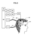
- Fig. 3 shows the configuration of an optical bioinstrumentation for living body in accordance with the first embodiment of the present invention.
- An anatomical image of a subject 301 constructed in advance using an imager of anatomical image 302 is saved in a memory unit 303.
- An optical measurement and control unit 309 reads the anatomical image from the memory unit 303, and displays it on a display unit 304.
- a selecting region unit 305 designates a region of interest, and a computing unit 306 calculates a recommended probe position according to the region of interest.
- An optical fiber 311 is fixed to a probe 307 mounted on the head of the subject 301.
- Light irradiated from an optical irradiator 310 in response to an instruction sent from the optical measurement and control unit 309 is applied to the scalp of the subject 301 over the optical fiber 311.
- the light passing through the head of the subject 301 travels along an optical fiber 313 coupled to the probe 307, and is then detected by an optical detector 312.
- the computing unit 306 then performs signal processing.
- a probe position sensor 308 fixed to the probe 307 detects a three-dimensional position of the probe 307.
- the computing unit 306 synthesizes the anatomical image saved in the memory unit 303, a representation expressing the recommended probe position, and a representation expressing the three-dimensional position of the probe 307 so as to construct a combined image, and displays the combined image on the display unit 304. Furthermore, when the distance between the recommended probe position and the three-dimensional position of the probe falls within a predetermined range of distances, the computing unit 306 causes an alarm device 314 to give the alarm.
- Fig. 3 has been described on the assumption that an anatomical image of a subject constructed in advance and a representation of a probe position are synthesized to construct a combined image.
- a brain functional image expressing the subject's brain functions and being constructed in advance may be employed.
- the brain functional image is constructed using, for example, an fMRI system, a PET system, an electroencephalography system, a magnetoencephalography system, an optical bioinstrumentation for living body, or a SPECT system.
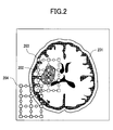
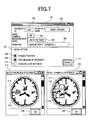
- Fig. 2 shows an example of display of the combined image.
- an anatomical image 201 that is, for example, a three-dimensional image constructed by an MRI system or an X-ray CT system.
- Reference numeral 202 denotes a representation expressing a region of interest that is delineated in advance and that is, for example, an image which is sampled from the anatomical image and which expresses an infarcted area, a motor area, or any other specific area.
- Reference numeral 203 denotes a representation expressing a recommended probe position calculated from the position of the region of interest.
- Reference numeral 204 denotes a representation expressing a current probe position detected by the probe position sensor 308.
- the representation of the recommended probe position 203 and the representation of the current probe position 204 are displayed in different colors so that they can be discriminated from each other.
- the representation of the region of interest 202 may be displayed while being superimposed on the anatomical image 201.
- the contour of the representation of the region of interest is displayed in a color different from the color of the anatomical image 201 and the colors of the representations of the recommended probe position 203 and current probe position 204, or displayed with their pixels set to a different pixel value.
- an indicator expressing the center of gravity of the region of interest may be displayed while being superimposed on the anatomical image.
- FIG. 2 has been described by taking for instance a case where representations expressing a region of interest and a probe position are displayed while being superimposed on an anatomical image.
- the representations expressing the region of interest and the probe position may be displayed while being superimposed on a brain functional image constructed by an fMRI system, a PET system, an electroencephalography system, a magnetoencephalography system, an optical bioinstrumentation for living body, or a SPECT system.
- a section expressed with an anatomical image is a plane
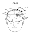
- the scalp to which the probe 307 is fixed has a curved surface. Therefore, when a representation expressing a probe position is displayed while being superimposed on the anatomical image, the image of the section on which a probe position is projected as shown in Fig. 15 must be displayed.
- a section parallel to a section A (1504) containing an infarcted area 1503 in the brain 1502 is regarded as a section to be expressed with an anatomical image.
- light irradiation (detection) fiber holders 1506 to 1508 equidistantly arranged on the probe are projected onto the section .
- the positions 1509 to 1511 are positions at which normals to the positions 1506 to 1508 on the curved surface extending along the scalp 1501 intersects the section A (1504).
- a representation of a probe position when it says that a representation of a probe position is displayed while being superimposed on an anatomical image, it means that a representation expressing a position formed by projecting the probe position is displayed while being superimposed on an anatomical image.
- a representation of a probe position is displayed while being superimposed on a brain functional image constructed through fMRI.
- an image of a desired section should preferably be able to be displayed instead of an image of a specific section.
- a means for retrieving an anatomical image of any section is needed.
- a means to select display section 802 is included in a window for displaying probe position 801 so that anatomical images 803 to 805 expressing desired sections and representations expressing probe positions 806 to 808 projected on the respective sections can be displayed.
- the windows for displaying probe position showing the images of a plurality of sections different windows may be opened for respective images of sections. Otherwise, a window for displaying probe position may be used in common, and the means to select display section may be used to change representations of probe positions and anatomical images on each of which a representation of a probe position is superimposed.
- three-dimensional anatomical images of desired sections are displayed. Even when a representation of a probe position may be displayed while being superimposed on a three-dimensional brain functional image constructed using an fMRI system, a PET system, an electroencephalography system, a magnetoencephalography system, an optical bioinstrumentation for living body, or a SPECT system, brain functional images of desired sections are displayed in the same manner.
- a representation expressing a lesion such as an infarcted area can be sampled based on a difference in contrast from a representation expressing a peripheral region and being contained in a diffusion-weighted image, a T2-weighted image, or any other kind of MRI image.
- a pointing device or the like is used to delineate a region of interest in an anatomical image.
- the difference in a pixel value from the representation of the peripheral area is utilized in order to automatically or semi-automatically sample a domain containing pixel values, which fall within a specific range, according to a region growing method or the like.
- a representation of a lesion is sampled as a representation of a region of interest
- images constructed according to various metric methods may have to be observed.
- a T1-weighted image, a T2-weighted image, a diffusion-weighted image, and a neuronal fiber tracking image that are kinds of MRI images and are by nature different from one another in terms of a contrast between representations of tissues are used to visualize various lesions.
- a combined image constructed by superimposing on an anatomical image a brain functional image constructed by an fMRI system, a PET system, an electroencephalography system, a magnetoencephalography system, an optical bioinstrumentation for living body, or a SPECT system may be employed. Otherwise, the brain functional image alone may be employed.
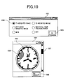
- an image selecting means shown in Fig. 10 should preferably be included.
- select image buttons 1002 are used to select a kind of image to be displayed.
- the select image buttons 1002 are, for example, radio buttons.
- a mouse is clicked within an OK button 1003
- a selected image 1005 is displayed within a region-of-interest/probe position display window 1004.
- a region of interest 1006 is delineated in an image, and the resultant representation of the region of interest 1006 is superimposed on the selected image.
- a section selecting means 1007 may be used to change images of sections to be displayed.
- the mouse is clicked within a reselection button 1008.
- a kind of image to be displayed is reselected within the select image window 1001.
- a Brodmann map may be employed.
- the Brodmann map shows the cerebral cortex that while functionally dividing the cerebral cortex into regions to which numbers are assigned.
- the relationship of correspondence between the numbers and coordinates representing positions in a standard brain defined by Talairach is already known. Consequently, coefficients of image transformation used to convert the standard brain into an anatomical image are calculated and then used to convert a region, which has a predetermined area number in the Brodmann map, into an image.
- a portion of the anatomical image expressing the region of the predetermined numbered area is constructed.
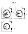
- Fig. 9 shows a region selecting means and an example of an image displayed in a case where a predetermined numbered area in the Brodmann map is regarded as a region of interest.
- a representation expressing a region of interest and a representation expressing a probe position are displayed while being superimposed on an anatomical image 902 of any section within a region-of-interest/probe position display window 901.
- any Brodmann area number 904 is selected and finalized with a click made in a selection button 905.
- characters indicating an area number may be entered or any other selecting method may be adopted.
- the region having the selected Brodmann area number 904 is converted into an image that will fit the anatomical image, and the resultant image is displayed as representations 906 and 907 expressing a region of interest while being superimposed on the anatomical image 902.
- a recommended probe position 908 is calculated based on the region of interest, and a representation expressing the recommended probe position is superimposed on the anatomical image 902.
- a means of detection of probe position includes, for example, a mechanical method, an optical method, a magnetometric sensor method, an acoustic method, and a method using camera scanning. Any of the methods may be adopted.
- the magnetometric probe position detecting method will be described in conjunction with Fig. 11.
- a magnetic source 1102 includes three coils that induce magnetic fields in three mutually orthogonal directions, and generates a three-dimensional magnetic field along with the flow of an alternating current induced by a drive circuit 1103.
- a magnetometric sensor 1107 is fixed to a probe 1104 mounted on the head of a subject 1101.
- the position at which the magnetometric sensor 1107 is fixed is, for example, a substantial midpoint (sampling point) between an irradiation fiber holder 1105 and a detection fiber holder 1106.
- at least three magnetometric sensors are fixed at different positions.
- the magnetometric sensor 1107 comprises three mutually orthogonal coils and transfers a detection signal to a detector circuit 1108.
- the detector circuit 1108 amplifies a current that flows through each of the coils when an alternating magnetic field induced by each of the coils included in the magnetic source 102 penetrates through each of the coils of the magnetometric sensor 1107.
- the magnetometric sensor 1107 is disposed at least one reference point 1113 on the subject 1101. Positional information on the reference point 1113 is transmitted to a unit to compute real space coordinate 1109.
- the reference point 1113 is a point on scalp defined in a ten/twenty method that is a standard method for disposing electrodes of EEG, for example, a root of nose (nasion), an occipital point (inion), or a right or left preauricular point.
- a reference point marker is attached to the reference point 1113 in order to calculate coordinates representing the reference point in a coordinate system defined for the anatomical image.
- a material making the reference point marker easily distinguishable in an anatomical image constructed by an imager of anatomical image should preferably be employed.
- a capsule enclosing vitamin D, vitamin E, or any other fat-soluble chemical substance is regarded as the reference point marker.
- X-ray CT a metallic ball that absorbs X-rays is regarded as the reference point marker.
- the unit to compute real space coordinate 1109 regards the position of the magnetic source 1102 as a reference point, and calculates real-space coordinates representing the positions of the magnetometric sensors 1107 attached to the probe 1104 and the reference point 1113 respectively.
- a unit to compute image space 1110 calculates coordinates representing the reference point 1113 in the coordinate system defined for the anatomical image on the basis of the position of the reference point marker. Furthermore, coordinates representing the position of the probe 1104 in the coordinate system defined for the anatomical image are calculated based on the coordinates representing the reference point 1113 in the coordinate system for the anatomical image, and the real-space coordinates representing the positions of the magnetometric sensors 107.
- a unit to combine images 1111 constructs a combined image, which has a representation expressing the position of the probe 1104 superimposed on the anatomical image, on the basis of the coordinates representing the position of the probe 1104 in the coordinate system defined for the anatomical image.
- the combined image is displayed on a display unit 1112.
- an arm of a manipulator is brought into contact with the reference point 1113 or an arbitrary point on the probe 1104.
- a potentiometer or an encoder is used to measure a linear displacement made by the arm and a rotational displacement made thereby.
- positional information on the arbitrary point to be discussed in a coordinate system defined for the manipulator is calculated.
- Positional information on the reference point is detected in the same manner as it is according to amethodusingmagnetometric sensors, whereby relative coordinates are calculated with the coordinates representing the reference point as a reference.
- positional information on the position of a representation expressing the reference point marker and being contained in the anatomical image is used to calculate coordinates representing the arbitrary position in the coordinate system defined for the anatomical image.
- a marker is attached to the reference point 1113 and an arbitrary position on the probe 1104.
- Coordinates representing the arbitrary position on the probe 1104 in the coordinate system defined for the anatomical image can be calculated based on images formed using a plurality of CCD cameras, the positions of the CCD cameras, and the positional information on the reference point 1113.
- an acoustic means of position tracking or an acoustic position sensor When an acoustic means of position tracking or an acoustic position sensor is employed, the time required for sound waves sent from a wave source to return to a detector after reflecting from an object, and an acoustic velocity are used to calculate the distance between the object and the acoustic position sensor. Otherwise, a phase difference between sound waves sent from the wave source and sound waves returned to the detector after reflecting from the object, and the acoustic velocity are used to calculate the distance between the object and the acoustic means of position tracking or the acoustic position sensor.
- An arbitrary position on the probe 1104 is selected as the object, and positional information on the arbitrary position to be discussed in a coordinate system defined for the acoustic position sensor is calculated.
- the reference point 1113 is selected as the object, and positional information on the reference point to be discussed in the coordinate system defined for the acoustic position sensor is calculated.
- relative coordinates are calculated with the coordinates representing the reference point as a reference.
- coordinates representing the arbitrary position on the probe to be discussed in the coordinate system defined for the anatomical image can be calculated based on the positional information on the position of the reference point marker discussed in the coordinate system defined for the anatomical image.
- a camera imaging method is such that a plurality of cameras are used to form images expressing a plurality of angles of a subject on which a probe is mounted.
- the images expressing the plurality of angles of the subject are used to calculate a three-dimensional outline image of the subject on which the probe is mounted.
- the three-dimensional image is saved in a memory means.
- the probe is remounted on the subject in order to form images expressing a plurality of angles of the subject.
- An outline image constructed from the images expressing the plurality of angles of the subject and a previous outline image are checked to see if they are consistent with each other.
- the sequence of changing probe positions, constructing images using the cameras, and verifying whether outline images are consistent with each other is repeated until the consistency between outline images reaches a predetermined degree.
- An image matching method may be employed in determining the degree of consistency between outline images.
- FIG. 5 shows an example of arrangement of holders of incident fiber 501 and holders of detection fiber 502 in a probe included in an optical bioinstrumentation for living body.
- the holders of incident fiber 501 and holders of detection fiber 502 are equidistantly and alternately arranged.
- a substantial midpoint between the irradiation fiber holder and the adjoining detection fiber holder is regarded as a sampling point 503.
- the sensitivity in detection of a signal in biomeasurement using light is maximized at the sampling point 503.
- a recommended probe position is determined so that the center of gravity 505 of a region of interest 504 will be located immediately below the sampling point 503.
- the probe has a plurality of sampling points, a plurality of recommended probe positions are conceivable.
- a sampling point located nearest the center of the probe, or in other words, a sampling point whose distance from a current probe position is shortest is selected in order to uniquely determine a recommended probe position.
- distances between adjoining ones of at least three points should preferably be taken into consideration.
- points 506, 507, and 508 are predefined as distance calculation points, and distances between a recommended probe position and associated distance calculation points on the probe 307 are calculated.
- an alarm device 314 gives the alarm.
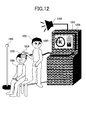
- an operator 1202 manually adjusts a probe position.
- the position of a probe 1203 mounted on the head of a subject 1201 is supported by the operator 1202, and detected by a position sensor composed of a magnetometric sensor 1204 fixed to the probe 1203 and a magnetic source 1205.
- a representation expressing the detected position of the probe 1203 is displayed within a window for displaying probe position 1207 opened in near-infrared measurement equipment 1206.
- an alarm device 1208 When the distance between the probe position and a recommended probe position falls within a predetermined range, an alarm device 1208 generates an alarm sound. Otherwise, an indicator 1209 reading a degree of consistency between the probe position and recommended probe position is displayed.
- the operator 1202 is notified of the fact that the probe 1203 is located at a desired position.
- the position sensor that detects a probe position is of a type employing a magnetometric sensor.
- the present invention is not limited to this type of position sensor.
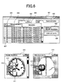
- previous data concerning the patient is read from a database.
- a list of previous data items is displayed in a window of choosing previous data 601.
- the patient ID and a patient name are presented in a field of patient's ID 602 and a field of patient's name 603. This makes it possible to identify the patient.
- a field of data number 604, a field of measurement date 605, and a field of remarks 606 are referenced in order to designate previous data 607.
- a region to be measured the contents of a task performed in measurement of brain functions, and other notes concerning conditions for measurement are entered. In the example shown in Fig.
- a mouse is clicked within the field of data number 604, the field of measurement date 605, or the field of remarks 606 on the line of the desired previous data included in the previous data list. Consequently, the selected line of the previous data is highlighted. In this state, the mouse is clicked within a button for displaying probe position 608 or a button for displaying data 609.
- a probe position at which the selected previous data is acquired is reflected on a window for displaying probe position 610.
- a representation expressing a probe position 612 at which the previous data is acquired is superimposed on an anatomical image 611.
- a representation expressing a current probe position 613 is also superimposed on the anatomical image.
- a near-infrared optical topographic image 615 of a region specified with the selected previous data is displayed within a window of displaying previous data 614.
- a current probe position 616 is also superimposed on the anatomical image.
- the button for displaying probe position 608 and the button for displaying data 609 may not be included independently of each other.
- one button may be used to display a representation expressing a previous probe position and previous data alternately along with a click.
- the window for displaying probe position 610 and the window of displaying previous data 614 may not be included independently of each other.
- a representation expressing a previous probe position and previous data may be superimposed on the same anatomical image.
- An input device such as a keyboard or a card reader is used to enter a patient ID and a patient name in a field of patient' s ID 702 and a field of patient's name 703 in a window of choosing previous data 701. Furthermore, a data number, a date of measurement, and notes on conditions for measurement are entered in a field of data number 704, a field of measurement date 705, and a field of remarks 706 respectively. Desired optional information such as a probe position 708, a region of interest 709, or a channel of interest 710 is selected in a field to specify save option 707. A mouse is then clicked within a save button 711. Consequently, information on a measured position is saved together with the patient ID, patient name, data number, date of measurement, notes on conditions for measurement, and measurement data.
- a region of interest 714 is delineated in an anatomical image 713 displayed in a window to select ROI 712.
- the mouse is then clicked within an OK button 715, whereby a representation expressing the region of interest to be saved is determined.
- the region of interest may be delineated using the pointing device as described above.
- a region growing method or the like may be adopted in order to segment a domain having pixel values that fall within a specific range. Otherwise, a Brodmann map or the like may be used to designate a specific region.
- the channel of interest 719 is selected as an optional item to be saved, the channel of interest 719 is designated on a representation expressing a probe position 718 in an anatomical image 717.
- the mouse is then clicked within the OK button 720, whereby a channel of interest to be saved is determined.
- a plurality of channels of interest 719 may be selected.
- an anatomical image of a subject 301 is constructed (step 102).
- the anatomical image is saved in a memory unit 303 (step 103). If a previously constructed anatomical image is employed, actions of steps 102 and 103 are not carried out.
- a probe position is determined prior to measurement to be performed using an optical bioinstrumentation for living body.
- a desired anatomical image is selected from among data items saved in the memory unit 303 (step 104), and then displayed on a display unit 304 (step 105).
- a representation expressing a probe position at which the previous data is acquired may be superimposed on the anatomical image (step 107).
- a selecting region unit 305 is used to delineate a region of interest (step 108).
- a computing unit 306 calculates a recommended probe position on the basis of the region of interest (step 109).
- the computing unit 306 calculates a distance R between a current probe position detected by a probe position sensor 308 and the recommended probe position (step 110). If the distance R gets smaller than a predefined threshold Rt (step 111), an acoustic or visual alarm is generated (step 112). Thereafter, an amount of light received is measured (step 113). The position of a probe is checked to see if the probe is located at a position at which sufficient measurement sensitivity is ensured. If the probe position must be readjusted because of insufficient sensitivity (step 114), the probe position is changed from one position to another. The actions of steps 110 to 113 are repeated until sufficient measurement sensitivity is ensured. After the probe position is determined, a biomedical optical signal is measured (step 115). Data and the probe position are saved in the memory unit 303 (step 116).
- an optical bioinstrumentation for living body is equipment for measuring a change in the concentration of hemoglobin in the cerebral cortex, and is unsuitable for measurement of a deep cerebral region.
- cerebral infarction occurs not only in a region near the cerebral cortex but also in a deep region.
- observation of an anatomical image containing information on the infarcted area has a significant meaning in determining a probe position for biomeasurement using light.
- a neural circuit in the motor system becomes defective. This will cause the activity of the right motor area 1404 located at the terminal of the right pyramidal tract 1402 to change. Otherwise, the activity of the left motor area 1405 located at the terminal of the left pyramidal tract 1403 substantially symmetrically to the right motor area should be observed.
- the second embodiment is almost identical to the first embodiment. Only a prominent point will be described in conjunction with Fig. 14 and Fig. 13.
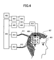
- FIG. 4 Another configuration of an optical bioinstrumentation for living body in accordance with the present invention will be described in conjunction with Fig. 4.
- An anatomical image of a subject 401 constructed in advance using an imager of anatomical image 402 is saved in a memory unit 403.
- An optical measurement and control unit 409 reads the anatomical image from the memory unit 403 and displays it on a display unit 404.
- a region selecting unit 405 is used to delineate a region of interest.
- a computing unit 406 calculates a recommended probe position according to the region of interest.
- An optical fiber 411 is coupled to a probe 407 mounted on the head of the subject 401.
- Light irradiated from an optical irradiator 410 in response to an instruction issued from the optical measurement and control unit 409 is applied to the scalp of the subject 401 after traveling along the optical fiber 411.
- the light passing through the scalp of the subject 401 travels along an optical fiber 413 coupled to the probe 407, and is then detected by an optical detector 412.
- a computing unit 406 performs signal processing.
- a probe position sensor 408 fixed to the probe 407 detects a three-dimensional position of the probe 407.
- the computing unit 406 constructs a combined image by superimposing on the anatomical image, which is saved in the memory unit 403, a representation expressing the recommended probe position and a representation expressing the three-dimensional position of the probe 407.
- the combined image is then displayed on the display unit 404.
- the computing unit 406 calculates the distance between the recommended probe position and the three-dimensional position of the probe 407.
- a probe position control unit 414 disposes the probe 407 at the recommended probe position according to the distance.
- a probe 1302 is fixed to a distal end of a probe position control arm 1306, and moved on the surface of the head of a subject 1301.
- the movement of the probe position control arm 1306 is controlled by a control unit incorporated in near-infrared measurement equipment 1305.
- a position sensor composed of a magnetometric sensor 1303 fixed to the probe 1302 and a magnetic source 1304 detects the position of the probe 1302.
- a representation expressing the position of the probe 1302 is displayed within a window for displaying probe position 1307 in the near-infrared measurement equipment 1305.
- the movement of the probe position control arm 1306 is ceased.
- the position of the probe 1302 is finalized.
- An indicator 1308 that reads a degree of consistency of the probe position with the recommended probe position may be used to indicate the degree of consistency of the probe position with the recommended probe position.
- the position sensor that detects a probe position is of the type employing a magnetometric sensor. The present invention is not limited to this type of position sensor.
- an optical bioinstrumentation for living body in which an optical irradiator and an optical detector are located at a position at which sensitivity is maximized and which exhibits high positional reproducibility at the time of remounting a probe.
Landscapes
- Health & Medical Sciences (AREA)
- Life Sciences & Earth Sciences (AREA)
- Physics & Mathematics (AREA)
- Engineering & Computer Science (AREA)
- Animal Behavior & Ethology (AREA)
- Veterinary Medicine (AREA)
- Pathology (AREA)
- Biomedical Technology (AREA)
- Heart & Thoracic Surgery (AREA)
- Medical Informatics (AREA)
- Molecular Biology (AREA)
- Surgery (AREA)
- Biophysics (AREA)
- General Health & Medical Sciences (AREA)
- Public Health (AREA)
- Human Computer Interaction (AREA)
- Nuclear Medicine, Radiotherapy & Molecular Imaging (AREA)
- Radiology & Medical Imaging (AREA)
- Neurology (AREA)
- Spectroscopy & Molecular Physics (AREA)
- Optics & Photonics (AREA)
- Magnetic Resonance Imaging Apparatus (AREA)
- Investigating Or Analysing Materials By Optical Means (AREA)
- Measurement Of The Respiration, Hearing Ability, Form, And Blood Characteristics Of Living Organisms (AREA)
- Measurement And Recording Of Electrical Phenomena And Electrical Characteristics Of The Living Body (AREA)
Applications Claiming Priority (1)
| Application Number | Priority Date | Filing Date | Title |
|---|---|---|---|
| JP2004310696A JP2006122086A (ja) | 2004-10-26 | 2004-10-26 | 生体光計測装置 |
Publications (1)
| Publication Number | Publication Date |
|---|---|
| EP1652470A1 true EP1652470A1 (en) | 2006-05-03 |
Family
ID=35615558
Family Applications (1)
| Application Number | Title | Priority Date | Filing Date |
|---|---|---|---|
| EP05017096A Withdrawn EP1652470A1 (en) | 2004-10-26 | 2005-08-05 | Optical measuring instrument for living body |
Country Status (4)
| Country | Link |
|---|---|
| US (1) | US7613502B2 (enExample) |
| EP (1) | EP1652470A1 (enExample) |
| JP (1) | JP2006122086A (enExample) |
| CN (1) | CN100493439C (enExample) |
Cited By (7)
| Publication number | Priority date | Publication date | Assignee | Title |
|---|---|---|---|---|
| WO2007072356A3 (en) * | 2005-12-21 | 2007-11-15 | Koninkl Philips Electronics Nv | Positioning system for patient monitoring sensors |
| WO2008109284A2 (en) | 2007-03-07 | 2008-09-12 | Ethicon Endo-Surgery, Inc | Recognizing a real world fiducial in patient image data |
| US8081810B2 (en) | 2007-03-22 | 2011-12-20 | Ethicon Endo-Surgery, Inc. | Recognizing a real world fiducial in image data of a patient |
| US8155728B2 (en) | 2007-08-22 | 2012-04-10 | Ethicon Endo-Surgery, Inc. | Medical system, method, and storage medium concerning a natural orifice transluminal medical procedure |
| US8457718B2 (en) | 2007-03-21 | 2013-06-04 | Ethicon Endo-Surgery, Inc. | Recognizing a real world fiducial in a patient image data |
| JP2013220326A (ja) * | 2012-04-19 | 2013-10-28 | Jichi Medical Univ | 経頭蓋脳機能解析方法 |
| CN104159523A (zh) * | 2012-03-29 | 2014-11-19 | 株式会社日立医疗器械 | 生物体光测量装置、生物体光测量方法以及移动型位置传感器用卡合部件 |
Families Citing this family (48)
| Publication number | Priority date | Publication date | Assignee | Title |
|---|---|---|---|---|
| JPWO2007135993A1 (ja) * | 2006-05-23 | 2009-10-01 | 株式会社日立メディコ | 生体光計測装置 |
| JP4661688B2 (ja) * | 2006-05-24 | 2011-03-30 | 株式会社島津製作所 | 光生体計測装置、光生体計測装置用プログラム及び光生体計測方法 |
| JP4876808B2 (ja) * | 2006-09-14 | 2012-02-15 | 株式会社島津製作所 | 脳機能データ制御装置 |
| DE102006059383A1 (de) * | 2006-12-15 | 2008-06-19 | Siemens Ag | Verfahren und Bildbearbeitungssystem zur Erzeugung von Ergebnisbildern eines Untersuchungsobjekts |
| US20110066020A1 (en) * | 2008-03-13 | 2011-03-17 | Alexander Svojanovsky | Multi-channel eeg electrode system |
| JP4968167B2 (ja) * | 2008-04-24 | 2012-07-04 | 株式会社島津製作所 | 光生体測定装置及びそれに用いられるホルダ配置支援システム |
| JP2010035637A (ja) * | 2008-07-31 | 2010-02-18 | Olympus Medical Systems Corp | 画像表示装置およびこれを用いた内視鏡システム |
| CN102170826B (zh) * | 2008-10-01 | 2013-07-24 | 株式会社日立医疗器械 | 生物体光计测装置、光照射位置及光检测位置或测定信道的位置显示方法 |
| EP2384431B1 (en) * | 2008-10-13 | 2017-11-29 | Hemics B.V. | Device and method for optically examining a turbid medium comprising joints |
| CN102427758B (zh) * | 2009-05-15 | 2015-01-07 | 皇家飞利浦电子股份有限公司 | 具有反馈校正的光学探头 |
| JP2010269021A (ja) * | 2009-05-22 | 2010-12-02 | Shimadzu Corp | 光測定装置 |
| US10299710B2 (en) * | 2009-07-21 | 2019-05-28 | Shimadzu Corporation | Organism optical measurement device |
| EP2489305B1 (en) | 2009-10-14 | 2017-07-05 | Hitachi, Ltd. | Biophotometer |
| JP5658993B2 (ja) * | 2010-12-15 | 2015-01-28 | 株式会社日立製作所 | 生体計測装置 |
| KR20120075084A (ko) * | 2010-12-28 | 2012-07-06 | 성균관대학교산학협력단 | 뇌혈류 역학의 광학 이미징 분석 방법 |
| JP5693984B2 (ja) * | 2011-02-02 | 2015-04-01 | 株式会社トプコン | 測定装置、測定方法、およびプログラム |
| JP6069885B2 (ja) * | 2012-05-14 | 2017-02-01 | 株式会社島津製作所 | 光計測システム及びその使用方法 |
| JP2015523133A (ja) * | 2012-06-15 | 2015-08-13 | コーニンクレッカ フィリップス エヌ ヴェ | 内視鏡低侵襲手術のための誘導切開計画 |
| JP5975437B2 (ja) * | 2012-06-29 | 2016-08-23 | 国立大学法人 筑波大学 | 生体計測装置の計測データ選択方法、生体計測装置の光出射位置決定方法、および生体計測装置 |
| JP2014030621A (ja) | 2012-08-03 | 2014-02-20 | Sony Corp | 情報処理装置、プログラム及び生体信号測定セット |
| JP6273207B2 (ja) * | 2012-11-14 | 2018-01-31 | 株式会社島津製作所 | 光生体計測装置及びそれに用いられる位置計測装置 |
| JP2014110844A (ja) * | 2012-12-05 | 2014-06-19 | Shimadzu Corp | 生体計測装置及びそれに用いられる位置計測装置 |
| DE202013012313U1 (de) | 2013-07-17 | 2016-02-25 | Fiagon Gmbh | Vorrichtung zur Anbindung eines medizinischen Instruments an ein Lageerfassungssystem und medizinisches Zeigerinstrument |
| DE102013217328A1 (de) * | 2013-08-30 | 2015-03-05 | Fiagon Gmbh | Verfahren und Vorrichtung zum Navigieren von aktiven chirurgischen Instrumenten |
| JP6079551B2 (ja) * | 2013-10-18 | 2017-02-15 | 株式会社島津製作所 | ホルダ位置合わせ支援装置および脳機能計測装置 |
| DE102013222230A1 (de) | 2013-10-31 | 2015-04-30 | Fiagon Gmbh | Chirurgisches Instrument |
| JP6079605B2 (ja) * | 2013-12-13 | 2017-02-15 | 株式会社島津製作所 | 脳機能計測装置および脳機能計測用データ処理装置 |
| JPWO2017170804A1 (ja) * | 2016-03-30 | 2019-02-14 | 株式会社NeU | 生体計測装置、情報処理プログラム、及び、生体計測方法 |
| US20170323069A1 (en) * | 2016-05-05 | 2017-11-09 | James Stewart Bates | Systems and methods for medical instrument patient measurements |
| US10861604B2 (en) * | 2016-05-05 | 2020-12-08 | Advinow, Inc. | Systems and methods for automated medical diagnostics |
| KR101856855B1 (ko) | 2016-08-10 | 2018-05-11 | 한국과학기술원 | 헤모다이나믹스 측정 결과를 표준화하기 위한 방법, 시스템 및 비일시성의 컴퓨터 판독 가능한 기록 매체 |
| WO2018200801A1 (en) * | 2017-04-27 | 2018-11-01 | Bendok Bernard R | 3d tracking-assisted functional brain region mapping |
| US11164679B2 (en) | 2017-06-20 | 2021-11-02 | Advinow, Inc. | Systems and methods for intelligent patient interface exam station |
| US11723579B2 (en) | 2017-09-19 | 2023-08-15 | Neuroenhancement Lab, LLC | Method and apparatus for neuroenhancement |
| US11717686B2 (en) | 2017-12-04 | 2023-08-08 | Neuroenhancement Lab, LLC | Method and apparatus for neuroenhancement to facilitate learning and performance |
| US12280219B2 (en) | 2017-12-31 | 2025-04-22 | NeuroLight, Inc. | Method and apparatus for neuroenhancement to enhance emotional response |
| US11478603B2 (en) | 2017-12-31 | 2022-10-25 | Neuroenhancement Lab, LLC | Method and apparatus for neuroenhancement to enhance emotional response |
| US11348688B2 (en) | 2018-03-06 | 2022-05-31 | Advinow, Inc. | Systems and methods for audio medical instrument patient measurements |
| US11364361B2 (en) | 2018-04-20 | 2022-06-21 | Neuroenhancement Lab, LLC | System and method for inducing sleep by transplanting mental states |
| CN108903915B (zh) * | 2018-07-24 | 2021-01-05 | 丹阳慧创医疗设备有限公司 | 一种用于近红外光谱脑功能成像系统的定位装置和方法 |
| WO2020056418A1 (en) | 2018-09-14 | 2020-03-19 | Neuroenhancement Lab, LLC | System and method of improving sleep |
| JP7211132B2 (ja) * | 2019-02-06 | 2023-01-24 | 株式会社リコー | 情報表示装置、情報表示方法、及び情報表示システム |
| EP3719749A1 (en) | 2019-04-03 | 2020-10-07 | Fiagon AG Medical Technologies | Registration method and setup |
| US11786694B2 (en) | 2019-05-24 | 2023-10-17 | NeuroLight, Inc. | Device, method, and app for facilitating sleep |
| US12350010B2 (en) * | 2019-12-05 | 2025-07-08 | Regents Of The University Of Minnesota | Systems and methods for multimodal neural sensing |
| CN111227790B (zh) * | 2020-01-08 | 2021-06-29 | 北京师范大学 | 一种基于脑功能区定位的近红外探头排布方法及头帽 |
| CN113925486A (zh) * | 2020-07-14 | 2022-01-14 | 先阳科技有限公司 | 组织成分测量方法、装置、电子设备、系统及存储介质 |
| CN114246556B (zh) * | 2022-03-01 | 2022-05-24 | 慧创科仪(北京)科技有限公司 | 用于近红外脑功能成像装置的定位方法、设备和存储介质 |
Citations (5)
| Publication number | Priority date | Publication date | Assignee | Title |
|---|---|---|---|---|
| JP2001198112A (ja) * | 2000-01-20 | 2001-07-24 | Hitachi Medical Corp | 生体光計測装置 |
| US20030004392A1 (en) * | 2001-06-28 | 2003-01-02 | Philipp Tanner | Method and device for transcranial magnetic stimulation |
| JP2003144437A (ja) * | 2001-11-12 | 2003-05-20 | Hitachi Medical Corp | 生体光計測装置 |
| EP1323380A2 (en) * | 2001-12-31 | 2003-07-02 | Medison Co., Ltd. | Method and apparatus for ultrasound imaging of a biopsy needle |
| EP1459677A1 (en) * | 2003-03-20 | 2004-09-22 | Communications Research Laboratory, Independent Administrative Institution | Method for mapping higher brain function and headgear for mapping higher brain function |
Family Cites Families (16)
| Publication number | Priority date | Publication date | Assignee | Title |
|---|---|---|---|---|
| JPS6363435A (ja) * | 1986-09-03 | 1988-03-19 | 株式会社東芝 | 断層面指定装置 |
| JPS63154155A (ja) * | 1986-12-19 | 1988-06-27 | 株式会社東芝 | 医用画像表示装置 |
| JP2534764B2 (ja) * | 1989-01-10 | 1996-09-18 | 株式会社東芝 | 衝撃波治療装置 |
| JP2797665B2 (ja) * | 1990-02-28 | 1998-09-17 | 株式会社島津製作所 | 脳磁計測装置 |
| US5662111A (en) * | 1991-01-28 | 1997-09-02 | Cosman; Eric R. | Process of stereotactic optical navigation |
| JPH06142096A (ja) * | 1992-11-09 | 1994-05-24 | Hitachi Ltd | 医用画像処理装置 |
| US5803909A (en) * | 1994-10-06 | 1998-09-08 | Hitachi, Ltd. | Optical system for measuring metabolism in a body and imaging method |
| JPH11155152A (ja) * | 1997-11-21 | 1999-06-08 | Canon Inc | 三次元形状情報入力方法及び装置及び画像入力装置 |
| FR2779339B1 (fr) * | 1998-06-09 | 2000-10-13 | Integrated Surgical Systems Sa | Procede et appareil de mise en correspondance pour la chirurgie robotisee, et dispositif de mise en correspondance en comportant application |
| US6466815B1 (en) * | 1999-03-30 | 2002-10-15 | Olympus Optical Co., Ltd. | Navigation apparatus and surgical operation image acquisition/display apparatus using the same |
| JP3839202B2 (ja) * | 1999-10-28 | 2006-11-01 | 株式会社日立製作所 | 生体光計測装置及びこの装置を機能させるためのプログラム |
| JP3796086B2 (ja) * | 1999-12-27 | 2006-07-12 | 株式会社日立製作所 | 生体光計測装置 |
| JP4078846B2 (ja) * | 2001-03-13 | 2008-04-23 | 株式会社島津製作所 | 断層撮影装置 |
| JP2003088528A (ja) * | 2001-09-18 | 2003-03-25 | Hitachi Medical Corp | 生体光計測装置 |
| JP2003344269A (ja) * | 2002-05-22 | 2003-12-03 | Hitachi Ltd | 生体光計測装置 |
| JP4157761B2 (ja) | 2002-12-16 | 2008-10-01 | 株式会社日立製作所 | 生体光計測用ヘッドギア及びそれを用いた生体光計測装置 |
-
2004
- 2004-10-26 JP JP2004310696A patent/JP2006122086A/ja active Pending
-
2005
- 2005-08-05 EP EP05017096A patent/EP1652470A1/en not_active Withdrawn
- 2005-08-17 US US11/205,184 patent/US7613502B2/en active Active
- 2005-08-17 CN CNB2005100905461A patent/CN100493439C/zh not_active Expired - Fee Related
Patent Citations (5)
| Publication number | Priority date | Publication date | Assignee | Title |
|---|---|---|---|---|
| JP2001198112A (ja) * | 2000-01-20 | 2001-07-24 | Hitachi Medical Corp | 生体光計測装置 |
| US20030004392A1 (en) * | 2001-06-28 | 2003-01-02 | Philipp Tanner | Method and device for transcranial magnetic stimulation |
| JP2003144437A (ja) * | 2001-11-12 | 2003-05-20 | Hitachi Medical Corp | 生体光計測装置 |
| EP1323380A2 (en) * | 2001-12-31 | 2003-07-02 | Medison Co., Ltd. | Method and apparatus for ultrasound imaging of a biopsy needle |
| EP1459677A1 (en) * | 2003-03-20 | 2004-09-22 | Communications Research Laboratory, Independent Administrative Institution | Method for mapping higher brain function and headgear for mapping higher brain function |
Cited By (10)
| Publication number | Priority date | Publication date | Assignee | Title |
|---|---|---|---|---|
| WO2007072356A3 (en) * | 2005-12-21 | 2007-11-15 | Koninkl Philips Electronics Nv | Positioning system for patient monitoring sensors |
| WO2008109284A2 (en) | 2007-03-07 | 2008-09-12 | Ethicon Endo-Surgery, Inc | Recognizing a real world fiducial in patient image data |
| EP2139391A4 (en) * | 2007-03-07 | 2010-05-26 | Ethicon Endo Surgery Inc | RECOGNITION OF A REAL MARK IN PATIENT IMAGE DATA |
| US8457718B2 (en) | 2007-03-21 | 2013-06-04 | Ethicon Endo-Surgery, Inc. | Recognizing a real world fiducial in a patient image data |
| US8081810B2 (en) | 2007-03-22 | 2011-12-20 | Ethicon Endo-Surgery, Inc. | Recognizing a real world fiducial in image data of a patient |
| US8155728B2 (en) | 2007-08-22 | 2012-04-10 | Ethicon Endo-Surgery, Inc. | Medical system, method, and storage medium concerning a natural orifice transluminal medical procedure |
| CN104159523A (zh) * | 2012-03-29 | 2014-11-19 | 株式会社日立医疗器械 | 生物体光测量装置、生物体光测量方法以及移动型位置传感器用卡合部件 |
| EP2832304A4 (en) * | 2012-03-29 | 2015-11-11 | Hitachi Medical Corp | DEVICE FOR MEASURING BIOLOGICAL LIGHT, METHOD FOR MEASURING BIOLOGICAL LIGHT, AND LOCKING ELEMENT FOR A MOBILE POSITION SENSOR |
| US9883825B2 (en) | 2012-03-29 | 2018-02-06 | Hitachi, Ltd. | Living body optical measurement apparatus, living body optical measurement method, and engagement member for mobile position sensor |
| JP2013220326A (ja) * | 2012-04-19 | 2013-10-28 | Jichi Medical Univ | 経頭蓋脳機能解析方法 |
Also Published As
| Publication number | Publication date |
|---|---|
| CN1765317A (zh) | 2006-05-03 |
| US7613502B2 (en) | 2009-11-03 |
| CN100493439C (zh) | 2009-06-03 |
| JP2006122086A (ja) | 2006-05-18 |
| US20060100526A1 (en) | 2006-05-11 |
Similar Documents
| Publication | Publication Date | Title |
|---|---|---|
| US7613502B2 (en) | Optical bioinstrumentation for living body | |
| US11380079B2 (en) | System and method for positional registration of medical image data | |
| CN100552715C (zh) | 用于融合图像显示的方法 | |
| US6628977B2 (en) | Method and system for visualizing an object | |
| EP1913875B1 (en) | Ultrasound system for fusing an ultrasound image and an external medical image | |
| US11109835B2 (en) | Three dimensional mapping display system for diagnostic ultrasound machines | |
| US6725079B2 (en) | Dual pointer device and method for surgical navigation | |
| JP5658747B2 (ja) | 針装置を用いるインターベンション中の記録済画像の再較正 | |
| US20170340241A1 (en) | Endoscopic examination support device, endoscopic examination support method, and endoscopic examination support program | |
| EP2839307B1 (en) | Magnetic resonance imaging with automatic selection of a recording sequence | |
| JP2009532162A (ja) | 患者に挿入されている対象物を取り巻く組織の判定 | |
| US7664542B2 (en) | Registering intra-operative image data sets with pre-operative 3D image data sets on the basis of optical surface extraction | |
| US20070066880A1 (en) | Image-based probe guidance system | |
| JP2000157537A (ja) | 患者の身体内に位置する医学器具の先端を表示するための方法 | |
| JP2002083281A (ja) | 実時間三次元再構成による容積の高品質表示を提供するイメージング装置および方法 | |
| JP2001170018A (ja) | 生体磁場計測装置 | |
| JP2002200058A (ja) | X線以外の血管内位置確認及び撮像方法 | |
| Koessler et al. | Automatic localization and labeling of EEG sensors (ALLES) in MRI volume | |
| JP4661688B2 (ja) | 光生体計測装置、光生体計測装置用プログラム及び光生体計測方法 | |
| US20050148853A1 (en) | Method for supporting navigation of a medical instrument, in particular of a catheter | |
| JP2001275989A (ja) | 生体信号計測装置 | |
| JP2002355229A (ja) | 磁界解析方法および電流分布可視化装置 | |
| JP3461380B2 (ja) | 生体機能計測における計測位置決定のための装置 | |
| JP5729490B2 (ja) | 光生体計測装置 | |
| JPH11332884A (ja) | 手術器具の位置表示装置 |
Legal Events
| Date | Code | Title | Description |
|---|---|---|---|
| PUAI | Public reference made under article 153(3) epc to a published international application that has entered the european phase |
Free format text: ORIGINAL CODE: 0009012 |
|
| AK | Designated contracting states |
Kind code of ref document: A1 Designated state(s): AT BE BG CH CY CZ DE DK EE ES FI FR GB GR HU IE IS IT LI LT LU LV MC NL PL PT RO SE SI SK TR |
|
| AX | Request for extension of the european patent |
Extension state: AL BA HR MK YU |
|
| 17P | Request for examination filed |
Effective date: 20061025 |
|
| AKX | Designation fees paid |
Designated state(s): DE FR GB IT |
|
| 17Q | First examination report despatched |
Effective date: 20110516 |
|
| STAA | Information on the status of an ep patent application or granted ep patent |
Free format text: STATUS: THE APPLICATION IS DEEMED TO BE WITHDRAWN |
|
| 18D | Application deemed to be withdrawn |
Effective date: 20110927 |