EP1644648B1 - Lagerring und radlagereinheit - Google Patents
Lagerring und radlagereinheit Download PDFInfo
- Publication number
- EP1644648B1 EP1644648B1 EP04762354A EP04762354A EP1644648B1 EP 1644648 B1 EP1644648 B1 EP 1644648B1 EP 04762354 A EP04762354 A EP 04762354A EP 04762354 A EP04762354 A EP 04762354A EP 1644648 B1 EP1644648 B1 EP 1644648B1
- Authority
- EP
- European Patent Office
- Prior art keywords
- bearing ring
- radially
- raceways
- rim
- bearing
- Prior art date
- Legal status (The legal status is an assumption and is not a legal conclusion. Google has not performed a legal analysis and makes no representation as to the accuracy of the status listed.)
- Expired - Lifetime
Links
- 238000005096 rolling process Methods 0.000 claims description 28
- 239000000463 material Substances 0.000 claims description 10
- 230000001154 acute effect Effects 0.000 claims 1
- 239000007858 starting material Substances 0.000 description 9
- 239000002184 metal Substances 0.000 description 6
- 238000005520 cutting process Methods 0.000 description 5
- 238000003754 machining Methods 0.000 description 4
- 238000000034 method Methods 0.000 description 4
- 238000004519 manufacturing process Methods 0.000 description 3
- 238000009434 installation Methods 0.000 description 2
- 229910000831 Steel Inorganic materials 0.000 description 1
- 238000010276 construction Methods 0.000 description 1
- 230000001627 detrimental effect Effects 0.000 description 1
- 238000005553 drilling Methods 0.000 description 1
- 230000002093 peripheral effect Effects 0.000 description 1
- 238000005498 polishing Methods 0.000 description 1
- 238000003825 pressing Methods 0.000 description 1
- 238000004080 punching Methods 0.000 description 1
- 230000000284 resting effect Effects 0.000 description 1
- 238000000926 separation method Methods 0.000 description 1
- 239000007787 solid Substances 0.000 description 1
- 239000010959 steel Substances 0.000 description 1
- 230000007704 transition Effects 0.000 description 1
Images


Classifications
-
- F—MECHANICAL ENGINEERING; LIGHTING; HEATING; WEAPONS; BLASTING
- F16—ENGINEERING ELEMENTS AND UNITS; GENERAL MEASURES FOR PRODUCING AND MAINTAINING EFFECTIVE FUNCTIONING OF MACHINES OR INSTALLATIONS; THERMAL INSULATION IN GENERAL
- F16C—SHAFTS; FLEXIBLE SHAFTS; ELEMENTS OR CRANKSHAFT MECHANISMS; ROTARY BODIES OTHER THAN GEARING ELEMENTS; BEARINGS
- F16C19/00—Bearings with rolling contact, for exclusively rotary movement
- F16C19/02—Bearings with rolling contact, for exclusively rotary movement with bearing balls essentially of the same size in one or more circular rows
- F16C19/14—Bearings with rolling contact, for exclusively rotary movement with bearing balls essentially of the same size in one or more circular rows for both radial and axial load
- F16C19/18—Bearings with rolling contact, for exclusively rotary movement with bearing balls essentially of the same size in one or more circular rows for both radial and axial load with two or more rows of balls
-
- F—MECHANICAL ENGINEERING; LIGHTING; HEATING; WEAPONS; BLASTING
- F16—ENGINEERING ELEMENTS AND UNITS; GENERAL MEASURES FOR PRODUCING AND MAINTAINING EFFECTIVE FUNCTIONING OF MACHINES OR INSTALLATIONS; THERMAL INSULATION IN GENERAL
- F16C—SHAFTS; FLEXIBLE SHAFTS; ELEMENTS OR CRANKSHAFT MECHANISMS; ROTARY BODIES OTHER THAN GEARING ELEMENTS; BEARINGS
- F16C19/00—Bearings with rolling contact, for exclusively rotary movement
- F16C19/02—Bearings with rolling contact, for exclusively rotary movement with bearing balls essentially of the same size in one or more circular rows
- F16C19/14—Bearings with rolling contact, for exclusively rotary movement with bearing balls essentially of the same size in one or more circular rows for both radial and axial load
- F16C19/18—Bearings with rolling contact, for exclusively rotary movement with bearing balls essentially of the same size in one or more circular rows for both radial and axial load with two or more rows of balls
- F16C19/181—Bearings with rolling contact, for exclusively rotary movement with bearing balls essentially of the same size in one or more circular rows for both radial and axial load with two or more rows of balls with angular contact
- F16C19/183—Bearings with rolling contact, for exclusively rotary movement with bearing balls essentially of the same size in one or more circular rows for both radial and axial load with two or more rows of balls with angular contact with two rows at opposite angles
- F16C19/184—Bearings with rolling contact, for exclusively rotary movement with bearing balls essentially of the same size in one or more circular rows for both radial and axial load with two or more rows of balls with angular contact with two rows at opposite angles in O-arrangement
- F16C19/186—Bearings with rolling contact, for exclusively rotary movement with bearing balls essentially of the same size in one or more circular rows for both radial and axial load with two or more rows of balls with angular contact with two rows at opposite angles in O-arrangement with three raceways provided integrally on parts other than race rings, e.g. third generation hubs
-
- B—PERFORMING OPERATIONS; TRANSPORTING
- B60—VEHICLES IN GENERAL
- B60B—VEHICLE WHEELS; CASTORS; AXLES FOR WHEELS OR CASTORS; INCREASING WHEEL ADHESION
- B60B27/00—Hubs
-
- F—MECHANICAL ENGINEERING; LIGHTING; HEATING; WEAPONS; BLASTING
- F16—ENGINEERING ELEMENTS AND UNITS; GENERAL MEASURES FOR PRODUCING AND MAINTAINING EFFECTIVE FUNCTIONING OF MACHINES OR INSTALLATIONS; THERMAL INSULATION IN GENERAL
- F16C—SHAFTS; FLEXIBLE SHAFTS; ELEMENTS OR CRANKSHAFT MECHANISMS; ROTARY BODIES OTHER THAN GEARING ELEMENTS; BEARINGS
- F16C33/00—Parts of bearings; Special methods for making bearings or parts thereof
- F16C33/30—Parts of ball or roller bearings
- F16C33/58—Raceways; Race rings
-
- F—MECHANICAL ENGINEERING; LIGHTING; HEATING; WEAPONS; BLASTING
- F16—ENGINEERING ELEMENTS AND UNITS; GENERAL MEASURES FOR PRODUCING AND MAINTAINING EFFECTIVE FUNCTIONING OF MACHINES OR INSTALLATIONS; THERMAL INSULATION IN GENERAL
- F16C—SHAFTS; FLEXIBLE SHAFTS; ELEMENTS OR CRANKSHAFT MECHANISMS; ROTARY BODIES OTHER THAN GEARING ELEMENTS; BEARINGS
- F16C33/00—Parts of bearings; Special methods for making bearings or parts thereof
- F16C33/30—Parts of ball or roller bearings
- F16C33/58—Raceways; Race rings
- F16C33/588—Races of sheet metal
-
- F—MECHANICAL ENGINEERING; LIGHTING; HEATING; WEAPONS; BLASTING
- F16—ENGINEERING ELEMENTS AND UNITS; GENERAL MEASURES FOR PRODUCING AND MAINTAINING EFFECTIVE FUNCTIONING OF MACHINES OR INSTALLATIONS; THERMAL INSULATION IN GENERAL
- F16C—SHAFTS; FLEXIBLE SHAFTS; ELEMENTS OR CRANKSHAFT MECHANISMS; ROTARY BODIES OTHER THAN GEARING ELEMENTS; BEARINGS
- F16C33/00—Parts of bearings; Special methods for making bearings or parts thereof
- F16C33/30—Parts of ball or roller bearings
- F16C33/58—Raceways; Race rings
- F16C33/64—Special methods of manufacture
-
- F—MECHANICAL ENGINEERING; LIGHTING; HEATING; WEAPONS; BLASTING
- F16—ENGINEERING ELEMENTS AND UNITS; GENERAL MEASURES FOR PRODUCING AND MAINTAINING EFFECTIVE FUNCTIONING OF MACHINES OR INSTALLATIONS; THERMAL INSULATION IN GENERAL
- F16C—SHAFTS; FLEXIBLE SHAFTS; ELEMENTS OR CRANKSHAFT MECHANISMS; ROTARY BODIES OTHER THAN GEARING ELEMENTS; BEARINGS
- F16C35/00—Rigid support of bearing units; Housings, e.g. caps, covers
- F16C35/04—Rigid support of bearing units; Housings, e.g. caps, covers in the case of ball or roller bearings
- F16C35/06—Mounting or dismounting of ball or roller bearings; Fixing them onto shaft or in housing
- F16C35/067—Fixing them in a housing
-
- F—MECHANICAL ENGINEERING; LIGHTING; HEATING; WEAPONS; BLASTING
- F16—ENGINEERING ELEMENTS AND UNITS; GENERAL MEASURES FOR PRODUCING AND MAINTAINING EFFECTIVE FUNCTIONING OF MACHINES OR INSTALLATIONS; THERMAL INSULATION IN GENERAL
- F16C—SHAFTS; FLEXIBLE SHAFTS; ELEMENTS OR CRANKSHAFT MECHANISMS; ROTARY BODIES OTHER THAN GEARING ELEMENTS; BEARINGS
- F16C2240/00—Specified values or numerical ranges of parameters; Relations between them
- F16C2240/30—Angles, e.g. inclinations
-
- F—MECHANICAL ENGINEERING; LIGHTING; HEATING; WEAPONS; BLASTING
- F16—ENGINEERING ELEMENTS AND UNITS; GENERAL MEASURES FOR PRODUCING AND MAINTAINING EFFECTIVE FUNCTIONING OF MACHINES OR INSTALLATIONS; THERMAL INSULATION IN GENERAL
- F16C—SHAFTS; FLEXIBLE SHAFTS; ELEMENTS OR CRANKSHAFT MECHANISMS; ROTARY BODIES OTHER THAN GEARING ELEMENTS; BEARINGS
- F16C2240/00—Specified values or numerical ranges of parameters; Relations between them
- F16C2240/30—Angles, e.g. inclinations
- F16C2240/34—Contact angles
-
- F—MECHANICAL ENGINEERING; LIGHTING; HEATING; WEAPONS; BLASTING
- F16—ENGINEERING ELEMENTS AND UNITS; GENERAL MEASURES FOR PRODUCING AND MAINTAINING EFFECTIVE FUNCTIONING OF MACHINES OR INSTALLATIONS; THERMAL INSULATION IN GENERAL
- F16C—SHAFTS; FLEXIBLE SHAFTS; ELEMENTS OR CRANKSHAFT MECHANISMS; ROTARY BODIES OTHER THAN GEARING ELEMENTS; BEARINGS
- F16C2240/00—Specified values or numerical ranges of parameters; Relations between them
- F16C2240/40—Linear dimensions, e.g. length, radius, thickness, gap
- F16C2240/70—Diameters; Radii
- F16C2240/76—Osculation, i.e. relation between radii of balls and raceway groove
-
- F—MECHANICAL ENGINEERING; LIGHTING; HEATING; WEAPONS; BLASTING
- F16—ENGINEERING ELEMENTS AND UNITS; GENERAL MEASURES FOR PRODUCING AND MAINTAINING EFFECTIVE FUNCTIONING OF MACHINES OR INSTALLATIONS; THERMAL INSULATION IN GENERAL
- F16C—SHAFTS; FLEXIBLE SHAFTS; ELEMENTS OR CRANKSHAFT MECHANISMS; ROTARY BODIES OTHER THAN GEARING ELEMENTS; BEARINGS
- F16C2326/00—Articles relating to transporting
- F16C2326/01—Parts of vehicles in general
- F16C2326/02—Wheel hubs or castors
Definitions
- the invention relates to a bearing ring of a wheel bearing unit, which is formed in one piece from cold-formed sheet metal and a wheel bearing unit with such a bearing ring.
- US 3,757,883 shows a wheel bearing unit in which the inner and the outer bearing ring are cold formed from sheet metal.
- the bearing rings are formed as a hollow cylinder about the axis of rotation of the wheel bearing unit and each have two raceways for rolling elements.
- the outer bearing ring has on its side facing away from the raceways on a radially outwardly directed flange with which the wheel bearing on the vehicle side is fixed.
- the inner bearing ring is provided with a likewise outwardly directed connection flange, on which the brake disc and the driven over the inner bearing ring wheel of a vehicle are attached.
- the raceways are radially at least partially recessed introduced into the respective bearing ring and separated by shoulders. At the radially outwardly projecting from the raceways Shoulders run off the raceways of the double row angular contact ball bearing.
- the non-cutting made of sheet metal bearing rings are very solid. This has a detrimental effect on the overall balance of unsprung on the vehicle Masses out. Due to their thick walls, the bearing rings are also relatively stiff, so that a possibly desired elastic deflection of the bearing rings is excluded. Such a bearing arrangement is only very difficult to pre-tension due to the high rigidity of the bearing rings.
- DE-U-7032767 shows a steering shaft bearing for supporting a steering shaft in a support tube, comprising a bearing outer ring with a radially inwardly curved half-wave profile section and with the ends of the half-wave profile section subsequent, substantially paraxial end portions.
- the object of the invention is therefore to provide a bearing ring for a wheel bearing unit, with its installation in the wheel bearing unit, the aforementioned disadvantages are avoided.
- a bearing ring of a wheel bearing unit is integrally formed substantially from formed sheet metal.
- the shape of the bearing ring with all its form elements is therefore made exclusively by forming.
- Cutting or machining is limited to a very small extent of machining compared to the scope of non-cutting machining.
- the term cold forming is understood to mean all the forming processes, where the contour of the hollow bearing ring by stretching or upsetting, widening or constriction and thereby plastic deformation of the starting material without material separation can be produced. Such methods are for. As drawing, deep drawing, rolling, pressing and combinations of the aforementioned methods.
- As blanks for the production of the bearing rings according to the invention are z. As pipes and sheets are provided. A blank from a tube is machined by flaring, rolling, necking, upsetting and flipping edges to the finished bearing ring. Made of sheet metal bearing rings according to the invention are prepared by drawing and other individual or combinations of the aforementioned method. Preferred materials are cold-formable bearing materials such. B. 100Cr6 or all suitable deep-drawing steels.
- the bearing ring Due to the annular groove acting as a relief notch in the load direction of the rolling elements, such a bearing ring is elastic and, due to the controlled texture of the material from the non-cutting production, extremely resilient. Furthermore, the bearing ring is characterized by a low weight, since starting material of low wall thickness or less sheet thickness is used. The thickness of the starting material is preferably in the range of 2.4 to 5 mm.
- the bearing ring is optionally designed as an outer bearing ring or inner bearing ring, but the outer bearing ring is given preference with this invention.
- a wheel bearing unit which has at least one of the bearing rings according to the invention.
- the wheel bearing has a double row angular contact ball bearing, preferably the O arrangement on.
- the wheel bearing unit according to the invention is formed at least with a bearing ring according to the invention and a support ring arranged concentrically to the bearing ring and arranged between the support ring and the bearing ring rows of rolling elements.
- the rolling elements are balls.
- both the bearing ring and the support ring each have two raceways for the balls.
- the wheel bearing unit is additionally provided with a flange, which receives a support ring with a track and on which another track is formed directly.
- FIG. 4 shows a wheel bearing unit 1 with a bearing ring 2 according to the invention for a driven and steered vehicle wheel.
- the bearing ring or the wheel bearing unit according to the invention are alternatively provided for non-driven and / or non-steered wheels.
- the wheel bearing unit 1 further comprises a flange 3, a support ring 4, two rows of rolling elements 5 in the form of balls, and seals 6 and 7. Each of the rows of rolling elements 5 is held and guided in each case with a cage 8.
- the wheel bearing unit 1 is fixed in a bore 9 with the formed as an outer ring bearing ring 2.
- the bearing ring 2 is pressed into the bore 9 and radially constricted so far elastically that the wheel bearing unit 1 is biased.
- the rolling elements 5 are based on one side inside the circumferential side of the bearing ring 2 on raceways 10 and 11 and in the other direction of raceways 12 and 13 from.
- the raceway 12 is formed on the support ring 4.
- the raceway 13 is introduced into the flange 3.
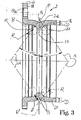
- the raceways 11 and 12 or 10 and 13 are each offset in the direction of the axis of rotation 1 a of the wheel bearing unit 1 and at least partially formed on a radially at least between the rows of rolling elements 5 from the bearing ring 2 protruding board 2a.
- the rows rolling elements 5 are arranged to each other in a so-called O-arrangement.
- the intersections of the lines of contact are A with the rotation axis 1 a of the respective rows axially away from each other.
- the pressure angle ⁇ is provided for such an arrangement in a range of 20 to 45 ° ( FIG. 3 . FIG. 4 ).
- the contact angle ⁇ is the angle which the connecting lines A between the two contact points B and C between rolling elements 5 and raceways 10 and 13 or 11 and 12 with the imaginary radial plane R "include 5 are not punctiform supported on the respective raceway 10,11,12 or 13, but at least under load tightly nestle in a raceways 10, 11, 12 or 13.
- the raceways 10, 11, 12 or 13 are therefore provided with a groove radius R. which is only slightly larger than the ball radius K of the rolling bodies 5.
- the ratio of groove radius R to ball radius K referred to in the art as "osculation”, is preferably for the raceways 10 and 11 on the outer ring, in this case on the bearing ring 2, [1,055: 1] as well as on the inner raceways 12 and 13 in this case on the support ring 3 and on the flange ring 3, [1, 035: 1] .
- the points of contact B and C are accordingly at Schmiegun g the centers of the contact or contact surfaces between the rolling element and the raceway, which are pierced by the connection lines A also known under the term "contact lines".
- the flange 3 is arranged about the rotation axis 1 a rotatable to the vehicle-fixed bearing ring 2 and takes the support ring 4 with.
- the support ring 4 is secured at least axially on the flange 3 by means of a flange flange 3 a of the flange ring resting against the support ring 4.
- From the flange 3 is radially from a connecting flange 3b, to which usually a brake disc and the rim of a vehicle wheel is attached.
- the flange 3 is driven and has for this purpose on its inner circumference a serration 14, in which engages a not described in detail here and driven drive element 15 positively.
- the bearing ring 2 is provided radially on the outside with an annular groove 16 (see also FIG. 3 ).
- the annular groove 16 connects radially outside the board 2a. According to the invention it is provided that the annular groove 16 extends radially into the board 2a and even partially extends radially to between the rows of rolling elements 5.
- the bearing ring 2 is elastically freely movable due to the annular groove 16 in the directions of the connecting lines A supporting directions.
- the material of the bearing ring 2 deforms under load in the region of the raceways 10 and 11 to the annular groove 16 out elastically, since the bearing ring 2 is not supported at this point due to the annular groove 16 radially in the receptacle of the bearing ring 2. This is advantageous both during elastic preloading of the wheel bearing unit 1 during installation and for the wheel bearing unit 1 in vehicle operation, since overloads due to short-term punctual voltage peaks in the rolling contact are avoided.
- the annular groove 16 is formed on the bearing ring 2 by constricting the bearing ring 2 in the direction of the axis of rotation to the board 2a.
- the board 2a is starting from the radially lowest point P (FIG. FIG. 3 ) of the annular groove 16 radially thicker than the wall thickness / thickness of the starting material, wherein the board 2a radially opposite to the flange 18 inwardly in the direction of the axis of rotation 1 a has.
- On the inner circumference of the rim 2a a cylindrical circumferential surface 17 pointing in the radial direction is formed.
- the flange 2a has a shoulder on the edge side for each of the raceways 10 and 11, respectively, and protrudes radially out of the bearing ring 2 via the raceways in the direction of the axis of rotation.
- the wall thickness of the bearing ring 2 is between the annular groove 16 and the respective raceway 10 and 11 at the strongest point S at least as thick as the wall thickness / thickness of the starting material.
- the bearing ring 2 has a hollow cylindrical portion 20 whose wall thickness is less than the wall thickness / thickness of the starting material ( FIG. 3 ).
- the flange 18 Radially from the bearing ring 2 goes outwardly integrally formed with the bearing ring 2 flange 18 from.
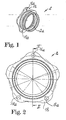
- circumferentially uniformly spaced through holes 18a are introduced ( FIGS. 1 and 2 ) by, as in FIG. 4 represented, in each case a bolt 19 engages.
- the bolts 19 of the bearing ring 2 is secured in the circumferential direction against micro-movements and circumferentially and axially against wandering from the bore 9.
- the bolts 19 are by means of interference fit alternatively by thread to the surrounding construction the wheel bearing unit 1 fixed.
- the flange 18 has the thickness H of the starting material.
- the thickness or wall thickness of the starting material is defined as a function of the blank used for the production of the bearing and summarized under the common term "strength".
- FIG. 4 shows, except for the partially radially extending into the rim extending in all the features of claim 1 of the present invention.
- FIG. 5 is an embodiment of a bearing ring 21 dargestell showing all the features of claim 1 of the present invention except for the partially radially into the board extending into it.
- the bearing ring 21 is integrally formed with a flange 22.
- the raceways 10 and 11 are partially formed on a board 23.
- the board 23 is provided on both sides with a shoulder for supporting rolling elements 5.
- the board 23 projects radially inward in the direction of the axis of rotation 21 a and has a cylindrical lateral surface 23 a facing towards the axis of rotation 21 a.
- the board 23 connects radially outwardly an annular groove 26.
- the bearing ring 21 extends axially on both sides in each of the raceway 10 and raceway 11 axially adjacent hollow cylindrical section 24 and 25, respectively.
- the radially largest wall thicknesses t of the hollow cylindrical sections 24 and 25 are smaller than the smallest radial distance T between the radially lowest point P 1 in the annular groove 26 and the cylindrical lateral surface 23 a.
- the extending through the raceways 10 and 11 contact lines A penetrate the axially centrally through the annular groove extending plane R "and include the pressure angle ⁇ between itself and the plane R" a.
- the rectified with the course of the contact lines A least wall thickness T 1 of the rim 23 is greater than the radially largest wall thickness t of the hollow cylindrical sections 24 and 25 in the region of the raceways 10 and 11.
- the contact lines A occur in the annular groove 26 outwardly from the bearing ring 23 out.
- the hollow cylindrical section 24 passes over an edge rounding 27 in the flange 22 via ( FIG. 7 ).
- the edge rounding 27 terminates in an annular end face 28.
- the planar surface 28 is radially outwardly of delimited by an axially protruding from the flange 23 projection 29.
- the projection 29 extends radially between the plane surface 28 and three flange holes 30 introduced in the flange 22.
- the flange holes 30 are from at least one further plane surface 31 outgoing through holes.
- the plane surface 31 is either as in FIG. 6 represented on the same plane as the plane surface 28 or runs parallel to this in another plane.
- the through holes are each provided at the transition to the plane surface 31 with a chamfer 32.
Landscapes
- Engineering & Computer Science (AREA)
- General Engineering & Computer Science (AREA)
- Mechanical Engineering (AREA)
- Manufacturing & Machinery (AREA)
- Rolling Contact Bearings (AREA)
- Mounting Of Bearings Or Others (AREA)
Applications Claiming Priority (2)
| Application Number | Priority Date | Filing Date | Title |
|---|---|---|---|
| DE10331180A DE10331180A1 (de) | 2003-07-10 | 2003-07-10 | Lagerring und Radlagereinheit |
| PCT/DE2004/001465 WO2005008085A1 (de) | 2003-07-10 | 2004-07-08 | Lagerring und radlagereinheit |
Publications (2)
| Publication Number | Publication Date |
|---|---|
| EP1644648A1 EP1644648A1 (de) | 2006-04-12 |
| EP1644648B1 true EP1644648B1 (de) | 2013-04-03 |
Family
ID=34071607
Family Applications (1)
| Application Number | Title | Priority Date | Filing Date |
|---|---|---|---|
| EP04762354A Expired - Lifetime EP1644648B1 (de) | 2003-07-10 | 2004-07-08 | Lagerring und radlagereinheit |
Country Status (9)
| Country | Link |
|---|---|
| US (1) | US7465102B2 (pt) |
| EP (1) | EP1644648B1 (pt) |
| JP (1) | JP2006528326A (pt) |
| KR (1) | KR20060032199A (pt) |
| CN (1) | CN100545471C (pt) |
| BR (1) | BRPI0412500A (pt) |
| CA (1) | CA2534817A1 (pt) |
| DE (1) | DE10331180A1 (pt) |
| WO (1) | WO2005008085A1 (pt) |
Cited By (1)
| Publication number | Priority date | Publication date | Assignee | Title |
|---|---|---|---|---|
| DE102023132983A1 (de) * | 2023-11-27 | 2025-05-28 | Schaeffler Technologies AG & Co. KG | Wälzlageranordnung und Verfahren zum Betrieb einer Wälzlageranordnung |
Families Citing this family (30)
| Publication number | Priority date | Publication date | Assignee | Title |
|---|---|---|---|---|
| EP1647418B1 (en) * | 2004-10-13 | 2012-06-27 | Nsk Ltd. | Hub unit with wheel support and bearing ring, and method of manufacturing the hub unit |
| ITTO20040875A1 (it) * | 2004-12-14 | 2005-03-14 | Skf Ab | Unita' cuscinetto per il mozzo della ruota di un autoveicolo. |
| ATE395520T1 (de) * | 2005-03-24 | 2008-05-15 | Skf Ab | Radlagereinheit für ein kraftfahrzeug |
| WO2007078616A2 (en) * | 2005-12-22 | 2007-07-12 | Timken Us Corporation | Tapered bearing and method for manufacturing |
| DE102006007580A1 (de) * | 2006-02-18 | 2007-09-06 | Schaeffler Kg | Rotierendes landwirtschaftliches Werkzeug mit Lageranordnung |
| JP2008074332A (ja) * | 2006-09-25 | 2008-04-03 | Jtekt Corp | 車輪用転がり軸受装置 |
| DE102006051644A1 (de) * | 2006-11-02 | 2008-05-08 | Schaeffler Kg | Radlagerung für Kraftfahrzeuge |
| JP4205752B2 (ja) * | 2006-11-07 | 2009-01-07 | Ntn株式会社 | 車輪用軸受装置 |
| DE112007002599T5 (de) | 2006-11-07 | 2010-01-14 | Ntn Corp. | Radlagervorrichtung für ein Fahrzeug |
| WO2008056446A1 (en) * | 2006-11-07 | 2008-05-15 | Ntn Corporation | Bearing device for wheel |
| JP4394736B2 (ja) * | 2007-03-07 | 2010-01-06 | Ntn株式会社 | 駆動車輪用軸受装置及びその組立方法 |
| US8753018B2 (en) * | 2007-03-09 | 2014-06-17 | Schaeffler Kg | Wheel end support bearing |
| CN101675259B (zh) | 2007-04-04 | 2011-12-28 | Ntn株式会社 | 车轮用轴承及具有该车轮用轴承的车轮用轴承装置 |
| JP2008284919A (ja) * | 2007-05-15 | 2008-11-27 | Ntn Corp | 車輪用軸受装置、車輪用軸受装置の組立方法、アセンブリ体、およびアセンブリ体の組立方法 |
| JP5570687B2 (ja) * | 2007-06-01 | 2014-08-13 | Ntn株式会社 | 車輪用軸受装置 |
| DE102007050215A1 (de) | 2007-10-04 | 2009-04-09 | Schaeffler Kg | Radlagerung für Kraftfahrzeuge |
| EP2432650B1 (en) * | 2009-05-18 | 2013-02-27 | Ab Skf | Wheel bearing unit and method for producing the same |
| IT1394904B1 (it) * | 2009-07-21 | 2012-07-20 | Skf Ab | Anello esterno di cuscinetto volvente |
| IT1399977B1 (it) | 2010-04-20 | 2013-05-09 | Skf Ab | Gruppo mozzo ruota a due corone di corpi volventi |
| IT1399978B1 (it) * | 2010-04-20 | 2013-05-09 | Skf Ab | Gruppo mozzo ruota a due corone di corpi volventi |
| ITTO20100330A1 (it) * | 2010-04-20 | 2011-10-21 | Skf Ab | Gruppo mozzo ruota asimmetrico |
| IT1399979B1 (it) * | 2010-04-20 | 2013-05-09 | Skf Ab | Gruppo mozzo ruota asimmetrico |
| ITTO20100328A1 (it) * | 2010-04-20 | 2011-10-21 | Skf Ab | Gruppo mozzo ruota a due corone di corpi volventi |
| CN103703262B (zh) * | 2011-06-21 | 2016-04-13 | 日本精工株式会社 | 滚动轴承单元 |
| US9550518B2 (en) * | 2013-12-31 | 2017-01-24 | Trw Automotive U.S. Llc | Electric power steering assembly |
| ITUA20162312A1 (it) * | 2016-04-05 | 2017-10-05 | Skf Ab | Gruppo cuscinetto-mozzo con mozzo-rotore. |
| CN106379111B (zh) * | 2016-11-15 | 2018-12-14 | 安徽江淮汽车集团股份有限公司 | 一种等速万向节与轮毂连接结构及汽车 |
| IT201900023205A1 (it) * | 2019-12-06 | 2021-06-06 | Skf Ab | Gruppo sospensione per veicoli, includente una unità mozzo ruota ed un montante o articolazione di sospensione |
| DE102019135117A1 (de) * | 2019-12-19 | 2021-06-24 | Hirschvogel Umformtechnik Gmbh | Fahrwerkbauteil, Anordnung von Fahrwerkbauteil und Lagerbauteil sowie Fahrzeug mit einer solchen Anordnung und Verfahren zu deren Herstellung |
| CN114590120A (zh) * | 2022-03-03 | 2022-06-07 | 吉林大学 | 一种集成制动器和轮毂电机的车轮总成 |
Citations (1)
| Publication number | Priority date | Publication date | Assignee | Title |
|---|---|---|---|---|
| DE7032767U (de) * | 1970-09-02 | 1970-11-19 | Star Kugelhalter Gmbh Dt | Lenkspindellager. |
Family Cites Families (19)
| Publication number | Priority date | Publication date | Assignee | Title |
|---|---|---|---|---|
| US2037982A (en) * | 1933-02-23 | 1936-04-21 | Gen Motors Corp | Bearing and bearing mounting |
| DE924924C (de) * | 1944-08-05 | 1955-03-10 | Star Kugelhalter Ges M B H Deu | Verfahren zur Herstellung spanlos gefertigter Laufringe fuer mehrreihige Waelzlager |
| FR1175133A (fr) * | 1957-05-15 | 1959-03-20 | Rene Prevost Et Cie Ets | Roulements simplifiés et démontables pour roues de patins à roulettes |
| NL164807C (nl) * | 1970-02-05 | 1981-02-16 | Skf Svenska Kullagerfab Ab | Voertuig met aangedreven en niet-aangedreven loop- wielen, voorzien van dezelfde lagereenheid. |
| US3757883A (en) * | 1971-02-03 | 1973-09-11 | Skf Nv | Wheel support for an engine propelled road vehicle |
| DE2556244B2 (de) * | 1975-12-13 | 1977-09-29 | Uni-Cardan Ag, 5204 Lohmar | Lagerungsanordnung einer ueber ein gleichlaufdrehgelenk antreibbaren radnabe |
| DE2636903A1 (de) * | 1976-08-17 | 1978-02-23 | Wagner & Co | Zwei- bzw. dreiteiliges, ein- oder doppelreihiges selbsthaltendes kugellager aus stahl, bestehend aus spanlos verformten kugellager-laufringen |
| DE8702275U1 (de) * | 1987-02-14 | 1987-04-02 | Wagner GmbH & Co, Fahrzeugteilefabrik, 6400 Fulda | Doppelreihiges Kugellager |
| SE461606B (sv) * | 1988-02-11 | 1990-03-05 | Skf Nova Ab | Foerfarande foer framstaellning av tvaaradiga vinkelkontaktkullager |
| JPH0396717A (ja) * | 1989-09-11 | 1991-04-22 | Koyo Seiko Co Ltd | ラジアル玉軸受 |
| JP2850182B2 (ja) * | 1993-04-14 | 1999-01-27 | 光洋精工株式会社 | 斜接玉軸受 |
| JPH07317777A (ja) * | 1994-05-20 | 1995-12-08 | Ntn Corp | ハブユニット軸受外輪およびその製造方法 |
| JP3526323B2 (ja) * | 1994-05-20 | 2004-05-10 | Ntn株式会社 | ハブユニット軸受外輪の製造方法 |
| DE29504068U1 (de) | 1995-03-09 | 1995-05-04 | Skf Gmbh | Lageranordnung |
| JPH09151950A (ja) | 1995-11-30 | 1997-06-10 | Ntn Corp | 自動車の車輪用軸受装置 |
| EP1319854B1 (en) * | 1997-01-17 | 2005-08-03 | Nsk Ltd | Bearing unit for vehicle wheel support |
| IT1308389B1 (it) | 1999-02-24 | 2001-12-17 | Skf Ind Spa | Cuscinetto per il mozzo della ruota di un autoveicolo e procedimentoper il montaggio del cuscinetto sulla sospensione di un autoveicolo. |
| JP4724970B2 (ja) * | 2001-07-19 | 2011-07-13 | 株式会社ジェイテクト | 車軸用軸受装置 |
| EP1329727A1 (en) * | 2001-10-18 | 2003-07-23 | Nsk Ltd | Rotation-speed sensor device |
-
2003
- 2003-07-10 DE DE10331180A patent/DE10331180A1/de not_active Ceased
-
2004
- 2004-07-08 CA CA002534817A patent/CA2534817A1/en not_active Abandoned
- 2004-07-08 KR KR1020067000621A patent/KR20060032199A/ko not_active Withdrawn
- 2004-07-08 JP JP2006522210A patent/JP2006528326A/ja active Pending
- 2004-07-08 BR BRPI0412500-2A patent/BRPI0412500A/pt not_active Application Discontinuation
- 2004-07-08 EP EP04762354A patent/EP1644648B1/de not_active Expired - Lifetime
- 2004-07-08 US US10/564,135 patent/US7465102B2/en not_active Expired - Fee Related
- 2004-07-08 WO PCT/DE2004/001465 patent/WO2005008085A1/de not_active Ceased
- 2004-07-08 CN CNB2004800197936A patent/CN100545471C/zh not_active Expired - Fee Related
Patent Citations (1)
| Publication number | Priority date | Publication date | Assignee | Title |
|---|---|---|---|---|
| DE7032767U (de) * | 1970-09-02 | 1970-11-19 | Star Kugelhalter Gmbh Dt | Lenkspindellager. |
Cited By (1)
| Publication number | Priority date | Publication date | Assignee | Title |
|---|---|---|---|---|
| DE102023132983A1 (de) * | 2023-11-27 | 2025-05-28 | Schaeffler Technologies AG & Co. KG | Wälzlageranordnung und Verfahren zum Betrieb einer Wälzlageranordnung |
Also Published As
| Publication number | Publication date |
|---|---|
| JP2006528326A (ja) | 2006-12-14 |
| CA2534817A1 (en) | 2005-01-27 |
| CN100545471C (zh) | 2009-09-30 |
| US7465102B2 (en) | 2008-12-16 |
| US20060171624A1 (en) | 2006-08-03 |
| CN1856658A (zh) | 2006-11-01 |
| WO2005008085A1 (de) | 2005-01-27 |
| BRPI0412500A (pt) | 2006-09-19 |
| KR20060032199A (ko) | 2006-04-14 |
| DE10331180A1 (de) | 2005-02-24 |
| EP1644648A1 (de) | 2006-04-12 |
Similar Documents
| Publication | Publication Date | Title |
|---|---|---|
| EP1644648A1 (de) | Lagerring und radlagereinheit | |
| DE10060638B4 (de) | Radlagereinheit | |
| DE102007027216A1 (de) | Verfahren zur spanlosen Herstellung eines Wälzlagers | |
| EP1704339B1 (de) | Aussenring eines radlagers und axiale sicherung des aussenringes | |
| EP1963693B1 (de) | Verfahren zur herstellung eines wälzlagerringes | |
| EP3218208B1 (de) | Elastisches rad für ein schienenfahrzeug | |
| DE102008029088A1 (de) | Tretlager für ein Fahrrad | |
| DE10359645B4 (de) | Radlagermodul in einem Radträger | |
| EP1694974B1 (de) | Radlager in einem radträger | |
| WO2008052875A1 (de) | Radlagerung für kraftfahrzeuge | |
| EP1212544B1 (de) | Kugelkäfig | |
| EP1694975B1 (de) | Aussenring eines radlagers in einem radträger | |
| EP3308043B1 (de) | Schrägkugellager mit kaltumgeformtem lagerring sowie verfahren zur fertigung eines lagerrings des schrägkugellagers | |
| DE3211096A1 (de) | Kugellager | |
| DE102013016177B4 (de) | Käfig für ein Wälzlager, insbesondere für ein Lager einer elektrischen Servolenkung eines Kraftfahrzeugs | |
| DE102019130286A1 (de) | Dichthülse mit kombinierten Axiallagermitteln für eine Druckmittel-Drehdurchführung | |
| WO2008128515A1 (de) | Lageranordnung einer über ein drehgelenk antreibbaren radnabe eines kraftfahrzeuges und verfahren zu ihrer herstellung | |
| DE102014203206A1 (de) | Genietete Radlagereinheit mit verbesserter Klemmkraft | |
| DE102021213242A1 (de) | Tripodegelenk und Herstellungsverfahren | |
| DE3703252C2 (pt) | ||
| DE102005017588B3 (de) | Verfahren zur Herstellung eines Kegelrollenlagerringes | |
| DE102009034770A1 (de) | Lageranordnung einer Radnabe eines Kraftfahrzeuges und Verfahren zu ihrer Herstellung | |
| DE102005005377B4 (de) | Außenring für ein Lager | |
| EP1812248B1 (de) | Einheit aus wenigstens einem träger und aus einem radlager | |
| EP1964694B1 (de) | Gelenk- und/oder Lageranordnung, insbesondere Hülsengelenk zur Anbindung von Radführungselementen eines Fahrzeugs, sowie Verfahren zur Herstellung einer Gelenk- und/oder Lageranordnung |
Legal Events
| Date | Code | Title | Description |
|---|---|---|---|
| PUAI | Public reference made under article 153(3) epc to a published international application that has entered the european phase |
Free format text: ORIGINAL CODE: 0009012 |
|
| 17P | Request for examination filed |
Effective date: 20051220 |
|
| AK | Designated contracting states |
Kind code of ref document: A1 Designated state(s): AT BE BG CH CY CZ DE DK EE ES FI FR GB GR HU IE IT LI LU MC NL PL PT RO SE SI SK TR |
|
| RAP1 | Party data changed (applicant data changed or rights of an application transferred) |
Owner name: SCHAEFFLER KG |
|
| DAX | Request for extension of the european patent (deleted) | ||
| RIN1 | Information on inventor provided before grant (corrected) |
Inventor name: STEINBERGER, WOLFGANG Inventor name: DOEPPLING, HORST Inventor name: HOFMANN, HEINRICH Inventor name: DLUGAI, DARIUS Inventor name: HEIM, JENS Inventor name: LANGER, ROLAND Inventor name: NIEBLING, PETER |
|
| 17Q | First examination report despatched |
Effective date: 20080519 |
|
| RAP1 | Party data changed (applicant data changed or rights of an application transferred) |
Owner name: SCHAEFFLER TECHNOLOGIES AG & CO. KG |
|
| GRAP | Despatch of communication of intention to grant a patent |
Free format text: ORIGINAL CODE: EPIDOSNIGR1 |
|
| GRAS | Grant fee paid |
Free format text: ORIGINAL CODE: EPIDOSNIGR3 |
|
| GRAA | (expected) grant |
Free format text: ORIGINAL CODE: 0009210 |
|
| AK | Designated contracting states |
Kind code of ref document: B1 Designated state(s): AT BE BG CH CY CZ DE DK EE ES FI FR GB GR HU IE IT LI LU MC NL PL PT RO SE SI SK TR |
|
| REG | Reference to a national code |
Ref country code: GB Ref legal event code: FG4D Free format text: NOT ENGLISH |
|
| REG | Reference to a national code |
Ref country code: CH Ref legal event code: EP Ref country code: AT Ref legal event code: REF Ref document number: 604920 Country of ref document: AT Kind code of ref document: T Effective date: 20130415 |
|
| REG | Reference to a national code |
Ref country code: IE Ref legal event code: FG4D Free format text: LANGUAGE OF EP DOCUMENT: GERMAN |
|
| REG | Reference to a national code |
Ref country code: DE Ref legal event code: R096 Ref document number: 502004014095 Country of ref document: DE Effective date: 20130606 |
|
| PG25 | Lapsed in a contracting state [announced via postgrant information from national office to epo] |
Ref country code: SI Free format text: LAPSE BECAUSE OF FAILURE TO SUBMIT A TRANSLATION OF THE DESCRIPTION OR TO PAY THE FEE WITHIN THE PRESCRIBED TIME-LIMIT Effective date: 20130403 |
|
| REG | Reference to a national code |
Ref country code: NL Ref legal event code: VDEP Effective date: 20130403 |
|
| PG25 | Lapsed in a contracting state [announced via postgrant information from national office to epo] |
Ref country code: PT Free format text: LAPSE BECAUSE OF FAILURE TO SUBMIT A TRANSLATION OF THE DESCRIPTION OR TO PAY THE FEE WITHIN THE PRESCRIBED TIME-LIMIT Effective date: 20130805 Ref country code: FI Free format text: LAPSE BECAUSE OF FAILURE TO SUBMIT A TRANSLATION OF THE DESCRIPTION OR TO PAY THE FEE WITHIN THE PRESCRIBED TIME-LIMIT Effective date: 20130403 Ref country code: SE Free format text: LAPSE BECAUSE OF FAILURE TO SUBMIT A TRANSLATION OF THE DESCRIPTION OR TO PAY THE FEE WITHIN THE PRESCRIBED TIME-LIMIT Effective date: 20130403 Ref country code: NL Free format text: LAPSE BECAUSE OF FAILURE TO SUBMIT A TRANSLATION OF THE DESCRIPTION OR TO PAY THE FEE WITHIN THE PRESCRIBED TIME-LIMIT Effective date: 20130403 Ref country code: ES Free format text: LAPSE BECAUSE OF FAILURE TO SUBMIT A TRANSLATION OF THE DESCRIPTION OR TO PAY THE FEE WITHIN THE PRESCRIBED TIME-LIMIT Effective date: 20130714 Ref country code: GR Free format text: LAPSE BECAUSE OF FAILURE TO SUBMIT A TRANSLATION OF THE DESCRIPTION OR TO PAY THE FEE WITHIN THE PRESCRIBED TIME-LIMIT Effective date: 20130704 |
|
| PG25 | Lapsed in a contracting state [announced via postgrant information from national office to epo] |
Ref country code: BG Free format text: LAPSE BECAUSE OF FAILURE TO SUBMIT A TRANSLATION OF THE DESCRIPTION OR TO PAY THE FEE WITHIN THE PRESCRIBED TIME-LIMIT Effective date: 20130703 Ref country code: CY Free format text: LAPSE BECAUSE OF FAILURE TO SUBMIT A TRANSLATION OF THE DESCRIPTION OR TO PAY THE FEE WITHIN THE PRESCRIBED TIME-LIMIT Effective date: 20130403 Ref country code: PL Free format text: LAPSE BECAUSE OF FAILURE TO SUBMIT A TRANSLATION OF THE DESCRIPTION OR TO PAY THE FEE WITHIN THE PRESCRIBED TIME-LIMIT Effective date: 20130403 |
|
| BERE | Be: lapsed |
Owner name: SCHAEFFLER TECHNOLOGIES A.G. & CO. KG Effective date: 20130731 |
|
| PG25 | Lapsed in a contracting state [announced via postgrant information from national office to epo] |
Ref country code: SK Free format text: LAPSE BECAUSE OF FAILURE TO SUBMIT A TRANSLATION OF THE DESCRIPTION OR TO PAY THE FEE WITHIN THE PRESCRIBED TIME-LIMIT Effective date: 20130403 Ref country code: EE Free format text: LAPSE BECAUSE OF FAILURE TO SUBMIT A TRANSLATION OF THE DESCRIPTION OR TO PAY THE FEE WITHIN THE PRESCRIBED TIME-LIMIT Effective date: 20130403 Ref country code: DK Free format text: LAPSE BECAUSE OF FAILURE TO SUBMIT A TRANSLATION OF THE DESCRIPTION OR TO PAY THE FEE WITHIN THE PRESCRIBED TIME-LIMIT Effective date: 20130403 Ref country code: CZ Free format text: LAPSE BECAUSE OF FAILURE TO SUBMIT A TRANSLATION OF THE DESCRIPTION OR TO PAY THE FEE WITHIN THE PRESCRIBED TIME-LIMIT Effective date: 20130403 |
|
| PLBE | No opposition filed within time limit |
Free format text: ORIGINAL CODE: 0009261 |
|
| STAA | Information on the status of an ep patent application or granted ep patent |
Free format text: STATUS: NO OPPOSITION FILED WITHIN TIME LIMIT |
|
| PG25 | Lapsed in a contracting state [announced via postgrant information from national office to epo] |
Ref country code: IT Free format text: LAPSE BECAUSE OF FAILURE TO SUBMIT A TRANSLATION OF THE DESCRIPTION OR TO PAY THE FEE WITHIN THE PRESCRIBED TIME-LIMIT Effective date: 20130403 Ref country code: MC Free format text: LAPSE BECAUSE OF FAILURE TO SUBMIT A TRANSLATION OF THE DESCRIPTION OR TO PAY THE FEE WITHIN THE PRESCRIBED TIME-LIMIT Effective date: 20130403 Ref country code: RO Free format text: LAPSE BECAUSE OF FAILURE TO SUBMIT A TRANSLATION OF THE DESCRIPTION OR TO PAY THE FEE WITHIN THE PRESCRIBED TIME-LIMIT Effective date: 20130403 |
|
| REG | Reference to a national code |
Ref country code: CH Ref legal event code: PL |
|
| 26N | No opposition filed |
Effective date: 20140106 |
|
| GBPC | Gb: european patent ceased through non-payment of renewal fee |
Effective date: 20130708 |
|
| REG | Reference to a national code |
Ref country code: DE Ref legal event code: R081 Ref document number: 502004014095 Country of ref document: DE Owner name: SCHAEFFLER TECHNOLOGIES GMBH & CO. KG, DE Free format text: FORMER OWNER: FAG KUGELFISCHER AG & CO. OHG, SCHAEFFLER KG, , DE Effective date: 20130411 Ref country code: DE Ref legal event code: R081 Ref document number: 502004014095 Country of ref document: DE Owner name: SCHAEFFLER TECHNOLOGIES GMBH & CO. KG, DE Free format text: FORMER OWNER: SCHAEFFLER TECHNOLOGIES AG & CO. KG, 91074 HERZOGENAURACH, DE Effective date: 20140214 Ref country code: DE Ref legal event code: R081 Ref document number: 502004014095 Country of ref document: DE Owner name: SCHAEFFLER TECHNOLOGIES AG & CO. KG, DE Free format text: FORMER OWNER: SCHAEFFLER TECHNOLOGIES AG & CO. KG, 91074 HERZOGENAURACH, DE Effective date: 20140214 Ref country code: DE Ref legal event code: R081 Ref document number: 502004014095 Country of ref document: DE Owner name: SCHAEFFLER TECHNOLOGIES AG & CO. KG, DE Free format text: FORMER OWNER: FAG KUGELFISCHER AG & CO. OHG, SCHAEFFLER KG, , DE Effective date: 20130411 Ref country code: DE Ref legal event code: R081 Ref document number: 502004014095 Country of ref document: DE Owner name: SCHAEFFLER TECHNOLOGIES AG & CO. KG, DE Free format text: FORMER OWNERS: FAG KUGELFISCHER AG & CO. OHG, 97421 SCHWEINFURT, DE; SCHAEFFLER KG, 91074 HERZOGENAURACH, DE Effective date: 20130411 |
|
| REG | Reference to a national code |
Ref country code: DE Ref legal event code: R097 Ref document number: 502004014095 Country of ref document: DE Effective date: 20140106 |
|
| REG | Reference to a national code |
Ref country code: IE Ref legal event code: MM4A |
|
| REG | Reference to a national code |
Ref country code: FR Ref legal event code: ST Effective date: 20140331 |
|
| PG25 | Lapsed in a contracting state [announced via postgrant information from national office to epo] |
Ref country code: CH Free format text: LAPSE BECAUSE OF NON-PAYMENT OF DUE FEES Effective date: 20130731 Ref country code: LI Free format text: LAPSE BECAUSE OF NON-PAYMENT OF DUE FEES Effective date: 20130731 Ref country code: GB Free format text: LAPSE BECAUSE OF NON-PAYMENT OF DUE FEES Effective date: 20130708 Ref country code: BE Free format text: LAPSE BECAUSE OF NON-PAYMENT OF DUE FEES Effective date: 20130731 |
|
| PG25 | Lapsed in a contracting state [announced via postgrant information from national office to epo] |
Ref country code: FR Free format text: LAPSE BECAUSE OF NON-PAYMENT OF DUE FEES Effective date: 20130731 |
|
| PG25 | Lapsed in a contracting state [announced via postgrant information from national office to epo] |
Ref country code: IE Free format text: LAPSE BECAUSE OF NON-PAYMENT OF DUE FEES Effective date: 20130708 |
|
| REG | Reference to a national code |
Ref country code: AT Ref legal event code: MM01 Ref document number: 604920 Country of ref document: AT Kind code of ref document: T Effective date: 20130708 |
|
| PG25 | Lapsed in a contracting state [announced via postgrant information from national office to epo] |
Ref country code: AT Free format text: LAPSE BECAUSE OF NON-PAYMENT OF DUE FEES Effective date: 20130708 |
|
| REG | Reference to a national code |
Ref country code: DE Ref legal event code: R081 Ref document number: 502004014095 Country of ref document: DE Owner name: SCHAEFFLER TECHNOLOGIES AG & CO. KG, DE Free format text: FORMER OWNER: SCHAEFFLER TECHNOLOGIES GMBH & CO. KG, 91074 HERZOGENAURACH, DE Effective date: 20150213 |
|
| PG25 | Lapsed in a contracting state [announced via postgrant information from national office to epo] |
Ref country code: TR Free format text: LAPSE BECAUSE OF FAILURE TO SUBMIT A TRANSLATION OF THE DESCRIPTION OR TO PAY THE FEE WITHIN THE PRESCRIBED TIME-LIMIT Effective date: 20130403 |
|
| PG25 | Lapsed in a contracting state [announced via postgrant information from national office to epo] |
Ref country code: HU Free format text: LAPSE BECAUSE OF FAILURE TO SUBMIT A TRANSLATION OF THE DESCRIPTION OR TO PAY THE FEE WITHIN THE PRESCRIBED TIME-LIMIT; INVALID AB INITIO Effective date: 20040708 Ref country code: LU Free format text: LAPSE BECAUSE OF NON-PAYMENT OF DUE FEES Effective date: 20130708 |
|
| PGFP | Annual fee paid to national office [announced via postgrant information from national office to epo] |
Ref country code: DE Payment date: 20150930 Year of fee payment: 12 |
|
| REG | Reference to a national code |
Ref country code: DE Ref legal event code: R119 Ref document number: 502004014095 Country of ref document: DE |
|
| PG25 | Lapsed in a contracting state [announced via postgrant information from national office to epo] |
Ref country code: DE Free format text: LAPSE BECAUSE OF NON-PAYMENT OF DUE FEES Effective date: 20170201 |
|
| P01 | Opt-out of the competence of the unified patent court (upc) registered |
Effective date: 20230523 |