EP1644595B1 - Schalung mit einhakbarer spannschlossvorrichtung - Google Patents
Schalung mit einhakbarer spannschlossvorrichtung Download PDFInfo
- Publication number
- EP1644595B1 EP1644595B1 EP04762335A EP04762335A EP1644595B1 EP 1644595 B1 EP1644595 B1 EP 1644595B1 EP 04762335 A EP04762335 A EP 04762335A EP 04762335 A EP04762335 A EP 04762335A EP 1644595 B1 EP1644595 B1 EP 1644595B1
- Authority
- EP
- European Patent Office
- Prior art keywords
- extension
- leg
- claw
- legs
- turnbuckle device
- Prior art date
- Legal status (The legal status is an assumption and is not a legal conclusion. Google has not performed a legal analysis and makes no representation as to the accuracy of the status listed.)
- Expired - Lifetime
Links
Images


Classifications
-
- E—FIXED CONSTRUCTIONS
- E04—BUILDING
- E04G—SCAFFOLDING; FORMS; SHUTTERING; BUILDING IMPLEMENTS OR AIDS, OR THEIR USE; HANDLING BUILDING MATERIALS ON THE SITE; REPAIRING, BREAKING-UP OR OTHER WORK ON EXISTING BUILDINGS
- E04G17/00—Connecting or other auxiliary members for forms, falsework structures, or shutterings
- E04G17/04—Connecting or fastening means for metallic forming or stiffening elements, e.g. for connecting metallic elements to non-metallic elements
- E04G17/045—Connecting or fastening means for metallic forming or stiffening elements, e.g. for connecting metallic elements to non-metallic elements being tensioned by wedge-shaped elements
-
- E—FIXED CONSTRUCTIONS
- E04—BUILDING
- E04G—SCAFFOLDING; FORMS; SHUTTERING; BUILDING IMPLEMENTS OR AIDS, OR THEIR USE; HANDLING BUILDING MATERIALS ON THE SITE; REPAIRING, BREAKING-UP OR OTHER WORK ON EXISTING BUILDINGS
- E04G17/00—Connecting or other auxiliary members for forms, falsework structures, or shutterings
-
- E—FIXED CONSTRUCTIONS
- E04—BUILDING
- E04G—SCAFFOLDING; FORMS; SHUTTERING; BUILDING IMPLEMENTS OR AIDS, OR THEIR USE; HANDLING BUILDING MATERIALS ON THE SITE; REPAIRING, BREAKING-UP OR OTHER WORK ON EXISTING BUILDINGS
- E04G9/00—Forming or shuttering elements for general use
-
- E—FIXED CONSTRUCTIONS
- E04—BUILDING
- E04G—SCAFFOLDING; FORMS; SHUTTERING; BUILDING IMPLEMENTS OR AIDS, OR THEIR USE; HANDLING BUILDING MATERIALS ON THE SITE; REPAIRING, BREAKING-UP OR OTHER WORK ON EXISTING BUILDINGS
- E04G9/00—Forming or shuttering elements for general use
- E04G9/02—Forming boards or similar elements
- E04G2009/023—Forming boards or similar elements with edge protection
- E04G2009/025—Forming boards or similar elements with edge protection by a flange of the board's frame
-
- Y—GENERAL TAGGING OF NEW TECHNOLOGICAL DEVELOPMENTS; GENERAL TAGGING OF CROSS-SECTIONAL TECHNOLOGIES SPANNING OVER SEVERAL SECTIONS OF THE IPC; TECHNICAL SUBJECTS COVERED BY FORMER USPC CROSS-REFERENCE ART COLLECTIONS [XRACs] AND DIGESTS
- Y10—TECHNICAL SUBJECTS COVERED BY FORMER USPC
- Y10T—TECHNICAL SUBJECTS COVERED BY FORMER US CLASSIFICATION
- Y10T403/00—Joints and connections
- Y10T403/29—Rotarily connected, differentially translatable members, e.g., turn-buckle, etc.
-
- Y—GENERAL TAGGING OF NEW TECHNOLOGICAL DEVELOPMENTS; GENERAL TAGGING OF CROSS-SECTIONAL TECHNOLOGIES SPANNING OVER SEVERAL SECTIONS OF THE IPC; TECHNICAL SUBJECTS COVERED BY FORMER USPC CROSS-REFERENCE ART COLLECTIONS [XRACs] AND DIGESTS
- Y10—TECHNICAL SUBJECTS COVERED BY FORMER USPC
- Y10T—TECHNICAL SUBJECTS COVERED BY FORMER US CLASSIFICATION
- Y10T403/00—Joints and connections
- Y10T403/32—Articulated members
- Y10T403/32254—Lockable at fixed position
- Y10T403/32426—Plural distinct positions
- Y10T403/32442—At least one discrete position
- Y10T403/32451—Step-by-step adjustment
- Y10T403/32459—Retainer extends through aligned recesses
-
- Y—GENERAL TAGGING OF NEW TECHNOLOGICAL DEVELOPMENTS; GENERAL TAGGING OF CROSS-SECTIONAL TECHNOLOGIES SPANNING OVER SEVERAL SECTIONS OF THE IPC; TECHNICAL SUBJECTS COVERED BY FORMER USPC CROSS-REFERENCE ART COLLECTIONS [XRACs] AND DIGESTS
- Y10—TECHNICAL SUBJECTS COVERED BY FORMER USPC
- Y10T—TECHNICAL SUBJECTS COVERED BY FORMER US CLASSIFICATION
- Y10T403/00—Joints and connections
- Y10T403/59—Manually releaseable latch type
-
- Y—GENERAL TAGGING OF NEW TECHNOLOGICAL DEVELOPMENTS; GENERAL TAGGING OF CROSS-SECTIONAL TECHNOLOGIES SPANNING OVER SEVERAL SECTIONS OF THE IPC; TECHNICAL SUBJECTS COVERED BY FORMER USPC CROSS-REFERENCE ART COLLECTIONS [XRACs] AND DIGESTS
- Y10—TECHNICAL SUBJECTS COVERED BY FORMER USPC
- Y10T—TECHNICAL SUBJECTS COVERED BY FORMER US CLASSIFICATION
- Y10T403/00—Joints and connections
- Y10T403/70—Interfitted members
- Y10T403/7062—Clamped members
Definitions
- the invention relates to a formwork with the features of the preamble of claim 1.
- a generic formwork is for example from the DE 35 45 273 A1 known.
- Concrete formwork elements are used to erect boundaries for concrete bodies to be cast, such as building walls. In order to obtain pourable boundaries, usually several concrete formwork elements must be firmly connected. Turnbuckles are used to connect the concrete formwork elements.
- the concrete formwork elements consist essentially of a formwork, a frame and bracing to stabilize the frame.
- the turnbuckles are arranged in the area of crossings of struts and frames.
- a claw of a turnbuckle engages around a frame portion of two concrete shell elements to be connected, and by means of, for example, a wedge, the two claws - and thus the concrete shell elements - braced against each other.
- Turnbuckles of the prior art such as according to the DE 35 45 273 A1 , abut with abutment surfaces of legs of the claws at the top of transverse struts of the concrete formwork elements.
- the turnbuckle To tighten the turnbuckle, the turnbuckle must first be aligned.
- lugs must be inserted at the free ends of the legs in vertically extending grooves in the frame sections of the two concrete formwork elements. Once the noses of the legs of both claws are in position at the same time, the wedge can be driven to brace the claws.
- the DE 84 23 109 U and the DE 100 28 556 C1 each disclose a turnbuckle device for clamping concrete formwork elements, with two displaceable claws and a wedge. At free ends of legs of the claws lugs are each provided with an extension which extends perpendicular to the plane of surfaces of the legs.
- the object of the present invention is to present with a turnbuckle device strained concrete formwork elements that are easier to align and assemble.
- a turnbuckle device for a formwork of the type presented at a nose of a Leg an extension is provided, which extends at least partially perpendicular to the plane of the contact surface of the leg of the contact surface away.
- Concrete formwork elements are welded together in the contact area of frame and struts for stabilization. While a bracing, in particular a transverse strut, is flat on its head region, the frame in the contact region has a depression or groove. The recess or groove serves in particular to allow engagement of the nose of the turnbuckle device, whereby the turnbuckle device is intended to be fixed in a direction perpendicular to the formwork facing.
- the depression or groove in the frame is partially covered by the head portion of the brace, leaving a cavity between the brace and the frame. If the recess is formed as a groove, then the cavity represents a breakthrough opening in the contact area.
- the bracing of the brace and the frame takes place only on the surfaces of the strut and the frame that are actually adjacent to one another, so that the cavity is retained after the welding.
- the extension according to the invention on the nose of a leg can protrude into this cavity.
- the extension depends on the contact surface of the leg.
- the extension can protrude both vertically and obliquely with respect to the contact surface.
- the extension on the nose takes on a hook function.
- the claw to which the extension belongs can not be displaced significantly in a direction parallel to the abutment surface of the leg in a state in which the extension engages the cavity between the frame and the brace.
- the turnbuckle device allows a simple and quick one-hand installation by a fitter.
- turnbuckle device To improve the hold of the turnbuckle device, it is also possible to provide a plurality of projections on lugs of different legs. The turnbuckle device must then be provided with sufficient clearance between the two claws in order to bring the turnbuckle device in a bracing position can.
- the extension is provided on a nose of a leg, wherein the leg is in the mounted state of the turnbuckle on two horizontally juxtaposed concrete formwork elements can be applied to an upper side of a strut.
- the extension with hook function is formed on one of the upper legs of a claw when the clamping direction of the claws is horizontal.
- the suspension of the turnbuckle in the bracing position for the fitter is particularly easy because gravity facilitates the installation of the turnbuckle in the usual position (ie with horizontal displacement of the claws for clamping) by fixing the turnbuckle in this usual position. Gravity acts as an additional means of alignment and fixation.
- the edges of the extension and the contact surface of the leg of the extension define the position of the claw of the leg with the extension.
- extension is arranged on a nose of a leg of a first claw of the two claws, and the wedge is held out in the second claw.
- the second claw is movable while driving the wedge, while the first claw remains stationary.
- the extension is designed as a hook.
- the extension may have, at its end remote from the contact surface, a projection which extends at least partially back to the contact surface parallel to the contact surface.
- suitable recesses may be provided at the head end of the strut.
- the extension completely penetrate the cavity between the strut and frame and the projection in turn surround the strut. As a result, the grip of the claw on the concrete formwork element can be improved.
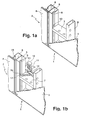
- FIG. 1a shows a schematic representation of conventional concrete formwork elements 1 and 2, which are arranged horizontally adjacent and to be firmly connected to each other.
- the concrete formwork elements each have a formwork skin 3, 4.
- the frames 5, 6 are reinforced and stiffened by struts 7, 8.
- the strut 7 is formed as a cross member and welded at its left in the picture head with the frame 5.
- the frame 5 has a groove-shaped recess 9, which extends in the vertical direction over the entire section of the frame 5 shown. In particular, the recess 9 also extends behind the left head end of the strut 7, whereby a cavity 10 in the form of an opening opening between the head end of the strut 7 and the frame 5 remains.
- FIG. 1b shows the concrete formwork elements 1, 2, which are connected to one another with a turnbuckle device 11 according to the invention.
- the turnbuckle device 11 has a first claw 12 and a second claw 13 and a wedge 18.
- the two claws 12, 13 each have two legs, of which in FIG. 1b only one upper leg 14 of the first claw 12 can be seen while the other legs are hidden.
- the legs surround above and below cross struts, of which only the strut 7 is visible, the frame 5, 6.
- lugs engage the front free ends of the legs in groove-shaped recesses 9, 15 of the frame 5, 6 a.
- a nose 16 of the leg 14 engages in the recess 9 of the frame 5 a.
- the nose 16 has a downwardly projecting extension 17. This protrudes into the cavity between the strut 7 and frame 5 inside.
- the extension 17 blocks a displacement of the leg 14 in the direction to the right on the strut 7.
- the remaining parts of the nose 16 block a displacement of the leg 14 in all other directions parallel to the support plane of the leg 14 on the strut 7, in particular on the formwork. 3 to or from this way or to the other concrete formwork element 2.
- the turnbuckle device 11 thus has only one degree of freedom, namely the position of the second claw 13 relative to the fixed first claw 12.
- the claws 12, 13 are guided like a rail into each other in the clamping direction.
- the degree of freedom of the second claw 13 can therefore be easily controlled by a fitter with one hand. This facilitates the assembly.
- FIG. 2 shows a schematic representation of a horizontal section through FIG. 1b just above the turnbuckle device 11 facing downward.
- the turnbuckle device 11 consists of the first claw 12, the second claw 13 and the wedge 18.
- the turnbuckle device 11 is loosely applied in the state shown and ready for bracing.
- the claws 12, 13 have legs 14, 20 which rest with their undersides as abutment surfaces on the upper sides of struts 7, 21.
- FIG. 3 This can be seen in the vertical section of FIG. 3 be better seen.
- the cutting plane of FIG. 3 is in FIG. 2 marked with "III”.
- FIG. 3 Conversely, the section plane of FIG. 2 in FIG. 3 marked with "II”.
- the legs 14 and 20 are each with their lower sides, namely the contact surfaces 30, 31, on the upper sides of the struts 7, 21. Also in FIG. 3 visible are a lower leg 32 of the first paw 12 and a lower leg 33 of the second paw 13. All legs 14, 20, 32, 33 protrude with lugs 16, 22, 34, 35 in the groove-shaped recesses 9, 15 of the frame 5, 6 inside.
- the extension 17 At the nose 16 of the leg 14 is the extension 17, which points away from the contact surface 30. In the case shown, the extension 17 is perpendicular from the plane of the contact surface 30 from. The extension 17 surrounds in the FIG. 3 left upper edge of the strut 7. This will cause movement of the leg 14 in the FIG.
- the extension 17 opposes this movement like a hook.
- the turnbuckle device 11 is not raised counter to the gravitational force
- the first claw 12 is fixed by the extension 17 which projects into the cavity 10 between the strut 7 and the frame 5.
- the first claw 12 has only in so far game as that the width of the extension 17 below the depth of the groove-shaped recess 9.
- the width of the extension 17 can be adjusted according to the invention to minimize the game of the depth of the recess 9.
- the lower legs 32, 33 thus do not require planar contact surfaces for engagement with the undersides of the struts 7, 21.
- FIGS. 4a to 4c show possible embodiments of the extensions according to the invention on the nose of a leg.
- FIG. 4a shows the simplest Embodiment, which also in the Figures 1b . 2 and 3 is realized.
- an extension 42 is mounted, which extends perpendicularly from the plane of a contact surface 43 away.
- the contact surface 43 is in FIG. 4a essentially the underside of the leg 41.
- an extension 44 which protrudes curved from the contact surface 43.
- the course of the extension 44 has a portion which projects perpendicularly from the abutment surface 43 and a portion which extends parallel to the abutment surface 43.
- the extension 44 extends partially perpendicular to the plane of the contact surface 43 of the contact surface 43 away.
- the Figure 4c shows an extension 45 which is formed as a hook.
- the extension 45 has a first portion 46, which extends perpendicularly away from the abutment surface 43, and a second portion 47, which has a vectorial portion parallel to the abutment surface 43 and faces the main part of the leg 41.
- the second section 47 may also be formed as a projection on the first section 46.
- a portion of the extension 45, here the second portion 47, is bent back to the leg 41, so to speak.
- the hook-shaped extension 45 is intended for use with specially designed struts, of which a possible strut 50 in a vertical section in FIG. 4d is shown.
- the strut 50 has on its the frame 5 facing the head side a recess 51 which is provided for the engagement of the second portion 47 of the hook-shaped extension 45.
- the leg 41 can be lifted only from the strut 51, when the nose 40 and the leg 41 is displaced to the inner edge 52 of the channel-shaped recess 9. This is when threading and unthreading the thigh 41 is easily taken into account by an installer, but the likelihood of unintentional slippage of the associated pawl from a tension-enabling position is greatly reduced.
- the assembly of the turnbuckle device according to the invention is facilitated.
- an extension is attached at least at one free end of a leg which is intended to rest on a strut of a concrete formwork element, which can be inserted into a cavity on the concrete formwork element.
- the extension has a hook function and fixes the leg and thus at least a part of the turnbuckle device in a suitable position for bracing the turnbuckle device.
Landscapes
- Engineering & Computer Science (AREA)
- Architecture (AREA)
- Mechanical Engineering (AREA)
- Civil Engineering (AREA)
- Structural Engineering (AREA)
- Forms Removed On Construction Sites Or Auxiliary Members Thereof (AREA)
- Joining Of Building Structures In Genera (AREA)
- Mutual Connection Of Rods And Tubes (AREA)
- Hooks, Suction Cups, And Attachment By Adhesive Means (AREA)
- Conveying And Assembling Of Building Elements In Situ (AREA)
Priority Applications (1)
| Application Number | Priority Date | Filing Date | Title |
|---|---|---|---|
| PL04762335T PL1644595T3 (pl) | 2003-07-05 | 2004-07-02 | Oszalowanie z zahaczanym urządzeniem mocującym |
Applications Claiming Priority (2)
| Application Number | Priority Date | Filing Date | Title |
|---|---|---|---|
| DE10330462A DE10330462A1 (de) | 2003-07-05 | 2003-07-05 | Einhakbare Spannschlossvorrichtung |
| PCT/DE2004/001409 WO2005005750A1 (de) | 2003-07-05 | 2004-07-02 | Einhakbare spannschlossvorrichtung |
Publications (2)
| Publication Number | Publication Date |
|---|---|
| EP1644595A1 EP1644595A1 (de) | 2006-04-12 |
| EP1644595B1 true EP1644595B1 (de) | 2010-09-29 |
Family
ID=33546863
Family Applications (1)
| Application Number | Title | Priority Date | Filing Date |
|---|---|---|---|
| EP04762335A Expired - Lifetime EP1644595B1 (de) | 2003-07-05 | 2004-07-02 | Schalung mit einhakbarer spannschlossvorrichtung |
Country Status (10)
| Country | Link |
|---|---|
| US (1) | US7648306B2 (pl) |
| EP (1) | EP1644595B1 (pl) |
| JP (1) | JP4362512B2 (pl) |
| KR (1) | KR100917950B1 (pl) |
| AT (1) | ATE483081T1 (pl) |
| CA (1) | CA2531076C (pl) |
| DE (2) | DE10330462A1 (pl) |
| ES (1) | ES2353197T3 (pl) |
| PL (1) | PL1644595T3 (pl) |
| WO (1) | WO2005005750A1 (pl) |
Cited By (2)
| Publication number | Priority date | Publication date | Assignee | Title |
|---|---|---|---|---|
| DE102018203764A1 (de) | 2018-03-13 | 2019-09-19 | Peri Gmbh | Verbinder |
| WO2023222642A1 (de) | 2022-05-19 | 2023-11-23 | Peri Se | Ausseneckvorrichtung fuer eine betonschalung und betonschalung |
Families Citing this family (16)
| Publication number | Priority date | Publication date | Assignee | Title |
|---|---|---|---|---|
| DE202006009860U1 (de) * | 2006-06-23 | 2006-08-24 | Doka Industrie Gmbh | Aussteifungsstruktur und Befestigungselement zur Aussteifung einer Stützen aufweisenden Unterstellung einer Deckenschalung |
| ITRM20070488A1 (it) * | 2007-09-19 | 2009-03-20 | Con Dor S R L | Dispositivo di bloccaggio per casseforme. |
| US8205854B2 (en) * | 2008-03-10 | 2012-06-26 | Western Forms, Inc. | Form clamp |
| RU2385397C1 (ru) * | 2008-08-05 | 2010-03-27 | Александр Михайлович Лютов | Замок для соединения элементов опалубки |
| DE102009036647A1 (de) * | 2009-08-07 | 2011-02-17 | Hofin Gmbh | Betonierungs-Schaltafel |
| DE102012214396A1 (de) | 2012-08-13 | 2014-02-13 | Harsco Infrastructure Services Gmbh | Wandschalung mit Verbindungseinrichtung |
| DE102013200147A1 (de) | 2013-01-08 | 2014-07-24 | Harsco Infrastructure Services Gmbh | Verbindungseinrichtung für Schaltafeln |
| DE202013104849U1 (de) | 2013-10-30 | 2013-11-13 | Harsco Infrastructure Services Gmbh | Wandschalung mit Parkposition für ein Keilschloss |
| KR101503180B1 (ko) * | 2013-12-10 | 2015-03-17 | 삼목에스폼 주식회사 | 거더 빔 체결용 클램프 |
| US12195961B2 (en) | 2016-06-24 | 2025-01-14 | Apache Industrial Services, Inc. | Formwork system |
| US10472823B2 (en) | 2016-06-24 | 2019-11-12 | Apache Industrial Services, Inc. | Formwork system |
| US11306492B2 (en) | 2016-06-24 | 2022-04-19 | Apache Industrial Services, Inc | Load bearing components and safety deck of an integrated construction system |
| US11976483B2 (en) | 2016-06-24 | 2024-05-07 | Apache Industrial Services, Inc | Modular posts of an integrated construction system |
| US11624196B2 (en) | 2016-06-24 | 2023-04-11 | Apache Industrial Services, Inc | Connector end fitting for an integrated construction system |
| DE102019200404A1 (de) | 2019-01-15 | 2020-07-16 | Hünnebeck GmbH | Halterung für ein Keilschloss |
| IT201900005146A1 (it) * | 2019-04-05 | 2020-10-05 | Faresin Formwork S P A | Morsa perfezionata per casserature per getti verticali |
Family Cites Families (14)
| Publication number | Priority date | Publication date | Assignee | Title |
|---|---|---|---|---|
| US1593610A (en) * | 1926-04-05 | 1926-07-27 | Kalman Steel Co | Form clamp |
| US3550898A (en) * | 1969-01-06 | 1970-12-29 | Tru Wall Concrete Forming Ltd | Concrete wall forms |
| JPS5142265B2 (pl) | 1973-05-07 | 1976-11-15 | ||
| JPS60121061A (ja) | 1983-12-06 | 1985-06-28 | Tounetsu:Kk | 耐火物で作られた非鉄金属の溶湯配管システム |
| JPS60121601U (ja) | 1984-01-26 | 1985-08-16 | アルプス電気株式会社 | チツプ部品 |
| DE8423109U1 (de) | 1984-08-03 | 1985-11-28 | Schliephacke, Heinrich, Dipl.-Ing., 4030 Ratingen | Verbindungsmittel für Schalungstafeln |
| DE8535906U1 (de) * | 1985-12-20 | 1991-03-28 | Peri-Werk Artur Schwörer GmbH & Co KG, 7912 Weißenhorn | Spannschloßvorrichtung für Betonschalelemente |
| DE3718615A1 (de) | 1987-06-03 | 1988-12-22 | Hollmann Niels | Rahmenschalungs-verbindungsklammer |
| GB2207209A (en) | 1987-07-17 | 1989-01-25 | Rapid Metal Developments Ltd | Load transmitting device |
| DE3734390C2 (de) * | 1987-10-10 | 1993-10-28 | Gerhard Dingler | Verbund für Fertigschalungen |
| DE8814208U1 (de) * | 1988-11-12 | 1989-01-05 | Maier, Josef, 7619 Steinach | Klammer zum Verbinden von Schaltafeln |
| DE19629660C1 (de) * | 1996-07-23 | 1997-11-20 | Maier G Paschal Werk | Klammer mit Spannbacken und einem diese verbindenden Träger |
| KR100730860B1 (ko) | 1999-09-23 | 2007-06-20 | 페리 게엠베하 | 턴버클 장치 |
| DE10028556C1 (de) | 2000-06-09 | 2001-09-27 | Meyer Keller Noe Schalttech | Spannzwinge zur Verbindung von zwei aneinandergrenzenden Schalungselementen einer Betonschalung |
-
2003
- 2003-07-05 DE DE10330462A patent/DE10330462A1/de not_active Ceased
-
2004
- 2004-07-02 KR KR1020067000172A patent/KR100917950B1/ko not_active Expired - Lifetime
- 2004-07-02 ES ES04762335T patent/ES2353197T3/es not_active Expired - Lifetime
- 2004-07-02 CA CA2531076A patent/CA2531076C/en not_active Expired - Lifetime
- 2004-07-02 AT AT04762335T patent/ATE483081T1/de active
- 2004-07-02 US US10/563,487 patent/US7648306B2/en not_active Expired - Lifetime
- 2004-07-02 JP JP2006517952A patent/JP4362512B2/ja not_active Expired - Lifetime
- 2004-07-02 EP EP04762335A patent/EP1644595B1/de not_active Expired - Lifetime
- 2004-07-02 DE DE502004011705T patent/DE502004011705D1/de not_active Expired - Lifetime
- 2004-07-02 PL PL04762335T patent/PL1644595T3/pl unknown
- 2004-07-02 WO PCT/DE2004/001409 patent/WO2005005750A1/de not_active Ceased
Cited By (3)
| Publication number | Priority date | Publication date | Assignee | Title |
|---|---|---|---|---|
| DE102018203764A1 (de) | 2018-03-13 | 2019-09-19 | Peri Gmbh | Verbinder |
| WO2023222642A1 (de) | 2022-05-19 | 2023-11-23 | Peri Se | Ausseneckvorrichtung fuer eine betonschalung und betonschalung |
| DE102022112619A1 (de) | 2022-05-19 | 2023-11-23 | Peri Se | Außeneckvorrichtung für eine Betonschalung und Betonschalung |
Also Published As
| Publication number | Publication date |
|---|---|
| US20060239769A1 (en) | 2006-10-26 |
| EP1644595A1 (de) | 2006-04-12 |
| ES2353197T3 (es) | 2011-02-28 |
| JP2007533874A (ja) | 2007-11-22 |
| US7648306B2 (en) | 2010-01-19 |
| PL1644595T3 (pl) | 2011-03-31 |
| WO2005005750A1 (de) | 2005-01-20 |
| CA2531076C (en) | 2011-01-04 |
| KR100917950B1 (ko) | 2009-09-21 |
| DE10330462A1 (de) | 2005-01-27 |
| JP4362512B2 (ja) | 2009-11-11 |
| DE502004011705D1 (pl) | 2010-11-11 |
| KR20060037323A (ko) | 2006-05-03 |
| CA2531076A1 (en) | 2005-01-20 |
| ATE483081T1 (de) | 2010-10-15 |
Similar Documents
| Publication | Publication Date | Title |
|---|---|---|
| EP1644595B1 (de) | Schalung mit einhakbarer spannschlossvorrichtung | |
| DE69708296T2 (de) | Vorgefertigtes betonelement für die herstellung einer konstruktion mit wandrundbögen | |
| DE3734390A1 (de) | Verbund fuer fertigschalungen | |
| EP1987213A1 (de) | Deckenschalungssystem | |
| EP1899552B1 (de) | Deckenschalungssystem | |
| WO2005040526A1 (de) | Schalungssystem | |
| EP0851075B1 (de) | Erhöhte Plattform oder Bühne, insbesondere ausgebildet als Deckenschalung für das Betonieren | |
| DE102012214396A1 (de) | Wandschalung mit Verbindungseinrichtung | |
| DE4007950C2 (de) | Vorrichtung zum Verbinden und Verspannen von Schaltafeln | |
| EP1601842A1 (de) | Bewehrungselemente und damit hergestellte stahl- oder spannbetonteile | |
| DE202006003836U1 (de) | Deckenschalungssystem | |
| CH644178A5 (de) | Vorrichtung zum verbinden von schaltafeln, insbesondere im bereich von abstufungen eines bauwerkes. | |
| WO1990005226A1 (de) | Vorrichtung zum verbinden von zubehörteilen mit schaltafeln | |
| EP1704293A1 (de) | Querriegel für eine betonrundschalung und betonrundschalung | |
| WO2022152594A1 (de) | Elementaufnahme | |
| AT412566B (de) | Baukastensystem | |
| DE3604252C2 (pl) | ||
| EP1646757B1 (de) | Spannschlossvorrichtung mit schräg geführtem keil | |
| DE2825710A1 (de) | Vorrichtung zum verbinden zweier schalungselemente einer betonschalung | |
| DE202011108692U1 (de) | Hohlprofil und Hallengerüst mit einem solchen Profil | |
| EP0851074B1 (de) | Gerüst, insbesondere für eine Plattform oder eine Bühne oder eine Deckenschalung | |
| EP1548200A2 (de) | Pfosten-Riegel-Fassade | |
| DE3338841A1 (de) | Fahrschiene fuer einschienenhaengebahn | |
| DE2150950C3 (de) | Kupplung fur Betonschalungselemente | |
| DE7740382U1 (de) | Verbund aus schaltafeln und spannschlossvorrichtungen |
Legal Events
| Date | Code | Title | Description |
|---|---|---|---|
| PUAI | Public reference made under article 153(3) epc to a published international application that has entered the european phase |
Free format text: ORIGINAL CODE: 0009012 |
|
| 17P | Request for examination filed |
Effective date: 20060206 |
|
| AK | Designated contracting states |
Kind code of ref document: A1 Designated state(s): AT BE BG CH CY CZ DE DK EE ES FI FR GB GR HU IE IT LI LU MC NL PL PT RO SE SI SK TR |
|
| DAX | Request for extension of the european patent (deleted) | ||
| 17Q | First examination report despatched |
Effective date: 20100127 |
|
| GRAP | Despatch of communication of intention to grant a patent |
Free format text: ORIGINAL CODE: EPIDOSNIGR1 |
|
| RTI1 | Title (correction) |
Free format text: FORMWORK WITH HOOKABLE TURNBUCKLE DEVICE |
|
| GRAS | Grant fee paid |
Free format text: ORIGINAL CODE: EPIDOSNIGR3 |
|
| GRAA | (expected) grant |
Free format text: ORIGINAL CODE: 0009210 |
|
| AK | Designated contracting states |
Kind code of ref document: B1 Designated state(s): AT BE BG CH CY CZ DE DK EE ES FI FR GB GR HU IE IT LI LU MC NL PL PT RO SE SI SK TR |
|
| REG | Reference to a national code |
Ref country code: GB Ref legal event code: FG4D Free format text: NOT ENGLISH |
|
| REG | Reference to a national code |
Ref country code: CH Ref legal event code: NV Representative=s name: RIEDERER HASLER & PARTNER PATENTANWAELTE AG Ref country code: CH Ref legal event code: EP |
|
| REG | Reference to a national code |
Ref country code: IE Ref legal event code: FG4D Free format text: LANGUAGE OF EP DOCUMENT: GERMAN |
|
| REF | Corresponds to: |
Ref document number: 502004011705 Country of ref document: DE Date of ref document: 20101111 Kind code of ref document: P |
|
| REG | Reference to a national code |
Ref country code: RO Ref legal event code: EPE |
|
| PG25 | Lapsed in a contracting state [announced via postgrant information from national office to epo] |
Ref country code: FI Free format text: LAPSE BECAUSE OF FAILURE TO SUBMIT A TRANSLATION OF THE DESCRIPTION OR TO PAY THE FEE WITHIN THE PRESCRIBED TIME-LIMIT Effective date: 20100929 |
|
| REG | Reference to a national code |
Ref country code: NL Ref legal event code: VDEP Effective date: 20100929 |
|
| PG25 | Lapsed in a contracting state [announced via postgrant information from national office to epo] |
Ref country code: SI Free format text: LAPSE BECAUSE OF FAILURE TO SUBMIT A TRANSLATION OF THE DESCRIPTION OR TO PAY THE FEE WITHIN THE PRESCRIBED TIME-LIMIT Effective date: 20100929 |
|
| REG | Reference to a national code |
Ref country code: ES Ref legal event code: FG2A Effective date: 20110216 |
|
| PG25 | Lapsed in a contracting state [announced via postgrant information from national office to epo] |
Ref country code: GR Free format text: LAPSE BECAUSE OF FAILURE TO SUBMIT A TRANSLATION OF THE DESCRIPTION OR TO PAY THE FEE WITHIN THE PRESCRIBED TIME-LIMIT Effective date: 20101230 Ref country code: SE Free format text: LAPSE BECAUSE OF FAILURE TO SUBMIT A TRANSLATION OF THE DESCRIPTION OR TO PAY THE FEE WITHIN THE PRESCRIBED TIME-LIMIT Effective date: 20100929 |
|
| REG | Reference to a national code |
Ref country code: PL Ref legal event code: T3 |
|
| REG | Reference to a national code |
Ref country code: IE Ref legal event code: FD4D |
|
| PG25 | Lapsed in a contracting state [announced via postgrant information from national office to epo] |
Ref country code: SK Free format text: LAPSE BECAUSE OF FAILURE TO SUBMIT A TRANSLATION OF THE DESCRIPTION OR TO PAY THE FEE WITHIN THE PRESCRIBED TIME-LIMIT Effective date: 20100929 Ref country code: NL Free format text: LAPSE BECAUSE OF FAILURE TO SUBMIT A TRANSLATION OF THE DESCRIPTION OR TO PAY THE FEE WITHIN THE PRESCRIBED TIME-LIMIT Effective date: 20100929 Ref country code: EE Free format text: LAPSE BECAUSE OF FAILURE TO SUBMIT A TRANSLATION OF THE DESCRIPTION OR TO PAY THE FEE WITHIN THE PRESCRIBED TIME-LIMIT Effective date: 20100929 Ref country code: PT Free format text: LAPSE BECAUSE OF FAILURE TO SUBMIT A TRANSLATION OF THE DESCRIPTION OR TO PAY THE FEE WITHIN THE PRESCRIBED TIME-LIMIT Effective date: 20110131 |
|
| PG25 | Lapsed in a contracting state [announced via postgrant information from national office to epo] |
Ref country code: IE Free format text: LAPSE BECAUSE OF FAILURE TO SUBMIT A TRANSLATION OF THE DESCRIPTION OR TO PAY THE FEE WITHIN THE PRESCRIBED TIME-LIMIT Effective date: 20100929 |
|
| PLBE | No opposition filed within time limit |
Free format text: ORIGINAL CODE: 0009261 |
|
| STAA | Information on the status of an ep patent application or granted ep patent |
Free format text: STATUS: NO OPPOSITION FILED WITHIN TIME LIMIT |
|
| PG25 | Lapsed in a contracting state [announced via postgrant information from national office to epo] |
Ref country code: DK Free format text: LAPSE BECAUSE OF FAILURE TO SUBMIT A TRANSLATION OF THE DESCRIPTION OR TO PAY THE FEE WITHIN THE PRESCRIBED TIME-LIMIT Effective date: 20100929 |
|
| 26N | No opposition filed |
Effective date: 20110630 |
|
| REG | Reference to a national code |
Ref country code: DE Ref legal event code: R097 Ref document number: 502004011705 Country of ref document: DE Effective date: 20110630 |
|
| BERE | Be: lapsed |
Owner name: PERI G.M.B.H. Effective date: 20110731 |
|
| PG25 | Lapsed in a contracting state [announced via postgrant information from national office to epo] |
Ref country code: MC Free format text: LAPSE BECAUSE OF NON-PAYMENT OF DUE FEES Effective date: 20110731 |
|
| PG25 | Lapsed in a contracting state [announced via postgrant information from national office to epo] |
Ref country code: BE Free format text: LAPSE BECAUSE OF NON-PAYMENT OF DUE FEES Effective date: 20110731 |
|
| PG25 | Lapsed in a contracting state [announced via postgrant information from national office to epo] |
Ref country code: CY Free format text: LAPSE BECAUSE OF EXPIRATION OF PROTECTION Effective date: 20100929 Ref country code: LU Free format text: LAPSE BECAUSE OF NON-PAYMENT OF DUE FEES Effective date: 20110702 |
|
| PG25 | Lapsed in a contracting state [announced via postgrant information from national office to epo] |
Ref country code: HU Free format text: LAPSE BECAUSE OF FAILURE TO SUBMIT A TRANSLATION OF THE DESCRIPTION OR TO PAY THE FEE WITHIN THE PRESCRIBED TIME-LIMIT Effective date: 20100929 |
|
| REG | Reference to a national code |
Ref country code: FR Ref legal event code: PLFP Year of fee payment: 13 |
|
| REG | Reference to a national code |
Ref country code: FR Ref legal event code: PLFP Year of fee payment: 14 |
|
| REG | Reference to a national code |
Ref country code: FR Ref legal event code: PLFP Year of fee payment: 15 |
|
| PGFP | Annual fee paid to national office [announced via postgrant information from national office to epo] |
Ref country code: RO Payment date: 20200629 Year of fee payment: 17 |
|
| PGFP | Annual fee paid to national office [announced via postgrant information from national office to epo] |
Ref country code: BG Payment date: 20200623 Year of fee payment: 17 |
|
| PGFP | Annual fee paid to national office [announced via postgrant information from national office to epo] |
Ref country code: ES Payment date: 20200807 Year of fee payment: 17 |
|
| PGFP | Annual fee paid to national office [announced via postgrant information from national office to epo] |
Ref country code: IT Payment date: 20200622 Year of fee payment: 17 |
|
| PG25 | Lapsed in a contracting state [announced via postgrant information from national office to epo] |
Ref country code: BG Free format text: LAPSE BECAUSE OF NON-PAYMENT OF DUE FEES Effective date: 20220131 |
|
| PG25 | Lapsed in a contracting state [announced via postgrant information from national office to epo] |
Ref country code: RO Free format text: LAPSE BECAUSE OF NON-PAYMENT OF DUE FEES Effective date: 20210702 |
|
| REG | Reference to a national code |
Ref country code: CH Ref legal event code: PK Free format text: BERICHTIGUNGEN |
|
| PG25 | Lapsed in a contracting state [announced via postgrant information from national office to epo] |
Ref country code: IT Free format text: LAPSE BECAUSE OF NON-PAYMENT OF DUE FEES Effective date: 20210702 |
|
| REG | Reference to a national code |
Ref country code: ES Ref legal event code: FD2A Effective date: 20220826 |
|
| PG25 | Lapsed in a contracting state [announced via postgrant information from national office to epo] |
Ref country code: ES Free format text: LAPSE BECAUSE OF NON-PAYMENT OF DUE FEES Effective date: 20210703 |
|
| REG | Reference to a national code |
Ref country code: AT Ref legal event code: HC Ref document number: 483081 Country of ref document: AT Kind code of ref document: T Owner name: PERI SE, DE Effective date: 20220930 |
|
| P01 | Opt-out of the competence of the unified patent court (upc) registered |
Effective date: 20230602 |
|
| PGFP | Annual fee paid to national office [announced via postgrant information from national office to epo] |
Ref country code: CZ Payment date: 20230602 Year of fee payment: 20 |
|
| PGFP | Annual fee paid to national office [announced via postgrant information from national office to epo] |
Ref country code: TR Payment date: 20230531 Year of fee payment: 20 Ref country code: PL Payment date: 20230531 Year of fee payment: 20 |
|
| PGFP | Annual fee paid to national office [announced via postgrant information from national office to epo] |
Ref country code: GB Payment date: 20230613 Year of fee payment: 20 Ref country code: CH Payment date: 20230802 Year of fee payment: 20 Ref country code: AT Payment date: 20230616 Year of fee payment: 20 |
|
| PGFP | Annual fee paid to national office [announced via postgrant information from national office to epo] |
Ref country code: FR Payment date: 20230726 Year of fee payment: 20 Ref country code: DE Payment date: 20230613 Year of fee payment: 20 |
|
| REG | Reference to a national code |
Ref country code: DE Ref legal event code: R071 Ref document number: 502004011705 Country of ref document: DE |
|
| PG25 | Lapsed in a contracting state [announced via postgrant information from national office to epo] |
Ref country code: GB Free format text: LAPSE BECAUSE OF EXPIRATION OF PROTECTION Effective date: 20240701 |
|
| REG | Reference to a national code |
Ref country code: CH Ref legal event code: PL |
|
| PG25 | Lapsed in a contracting state [announced via postgrant information from national office to epo] |
Ref country code: CZ Free format text: LAPSE BECAUSE OF EXPIRATION OF PROTECTION Effective date: 20240702 |
|
| REG | Reference to a national code |
Ref country code: GB Ref legal event code: PE20 Expiry date: 20240701 |
|
| PG25 | Lapsed in a contracting state [announced via postgrant information from national office to epo] |
Ref country code: GB Free format text: LAPSE BECAUSE OF EXPIRATION OF PROTECTION Effective date: 20240701 Ref country code: CZ Free format text: LAPSE BECAUSE OF EXPIRATION OF PROTECTION Effective date: 20240702 |
|
| REG | Reference to a national code |
Ref country code: AT Ref legal event code: MK07 Ref document number: 483081 Country of ref document: AT Kind code of ref document: T Effective date: 20240702 |