EP1640745B1 - Procédé et système de détection d'obstacle, en particulier pour des systèmes pour aider le stationnement des véhicules - Google Patents
Procédé et système de détection d'obstacle, en particulier pour des systèmes pour aider le stationnement des véhicules Download PDFInfo
- Publication number
- EP1640745B1 EP1640745B1 EP05020425A EP05020425A EP1640745B1 EP 1640745 B1 EP1640745 B1 EP 1640745B1 EP 05020425 A EP05020425 A EP 05020425A EP 05020425 A EP05020425 A EP 05020425A EP 1640745 B1 EP1640745 B1 EP 1640745B1
- Authority
- EP
- European Patent Office
- Prior art keywords
- sensors
- obstacle
- priority
- signals
- obstacle detection
- Prior art date
- Legal status (The legal status is an assumption and is not a legal conclusion. Google has not performed a legal analysis and makes no representation as to the accuracy of the status listed.)
- Not-in-force
Links
Images


Classifications
-
- G—PHYSICS
- G01—MEASURING; TESTING
- G01S—RADIO DIRECTION-FINDING; RADIO NAVIGATION; DETERMINING DISTANCE OR VELOCITY BY USE OF RADIO WAVES; LOCATING OR PRESENCE-DETECTING BY USE OF THE REFLECTION OR RERADIATION OF RADIO WAVES; ANALOGOUS ARRANGEMENTS USING OTHER WAVES
- G01S15/00—Systems using the reflection or reradiation of acoustic waves, e.g. sonar systems
- G01S15/88—Sonar systems specially adapted for specific applications
- G01S15/93—Sonar systems specially adapted for specific applications for anti-collision purposes
- G01S15/931—Sonar systems specially adapted for specific applications for anti-collision purposes of land vehicles
- G01S2015/932—Sonar systems specially adapted for specific applications for anti-collision purposes of land vehicles for parking operations
Definitions
- the present invention relates to an obstacle detection method and system, particularly for systems designed to facilitate the parking of motor vehicles.
- Systems using ultrasonic sensors are mainly used for measuring the distance between an obstacle and a motor vehicle; these sensors detect a signal emitted previously by a radiating element located in the vicinity of the sensor and reflected by an obstacle that lies proximate to the vehicle.
- the received return signal known as echo signal
- the sensor During an adequate time window, the received return signal, known as echo signal, is compared with a threshold value, and if said threshold value is exceeded, the sensor generates a warning signal.
- Incorrect warning signals refer in particular to signals reflected by objects that do not constitute a danger of collision with the vehicle, such as for example the ground, the optional towing hook mounted on the vehicle, particularly distant obstacles, or signals caused by noise.
- the time window so as to exclude from the comparison with the threshold values the signals caused by particularly distant obstacles.
- the duration of the time window in fact determines the monitoring depth of the system.
- the threshold values can vary according to time.
- the threshold values are reduced monotonically over time until the end of the time window, in order to prevent the system from generating warning signals caused by extremely proximate signals produced by the reflection of the ultrasound for example against the ground or against the towing hook.
- threshold values adapt the threshold values to the physical parameters of the car in order to further increase the precision of the system. Moreover, these threshold values are changed dynamically also according to the direction of travel of the vehicle, so as to increase the sensitivity of the sensors located in the direction of travel and reduce the sensitivity of the remaining ones.
- one of the problems that most significantly affect the sensing devices of the background art is reliability, i.e., the assurance that the warning signals are emitted exclusively at an obstacle.
- reliability i.e., the assurance that the warning signals are emitted exclusively at an obstacle.
- a safety system for a motor vehicle including a processor for predicting the collision of an obstacle with the motor vehicle and for activating in reply various safety devices, such as a seat belt and an air bag, wherein the processor receives the output of a plurality of sensors including a radar microwave wave system for generating and propagating electromagnetic radiation waves and suitable to receive reflected waves.
- the aim of the present invention is to eliminate the drawbacks mentioned above in known types of obstacle detection system, by providing an obstacle detection system that minimizes the emission of incorrect warning signals and thus increases the precision of said system.
- an object of the present invention is to provide an obstacle detection system that is capable of adapting the sensitivity of the sensors to physical and environmental parameters and to the arrangement of the obstacles.
- Another object of the present invention is to provide an obstacle detection system that is more flexible and optimized.
- Another object of the present invention is to provide an obstacle detection system that requires a reduced number of electronic components for its operation.
- an obstacle detection system which comprises a control unit and a plurality of sensors, said sensors comprising means for emitting an ultrasonic signal and for receiving an echo signal reflected by at least one obstacle and means for the parametric evaluation of received echo signals, characterized in that the means for parametric evaluation comprise means suitable to determine, for each sensing, the number of times for which the received signals are repeated and to reject the signals that are repeated for a number of times that is lower than a preset number.
- the parametric evaluation means further comprise means suitable to drive the power radiated by the signal emission means and means suitable to compare the signals received by the echo signal receiving means with threshold values.
- an obstacle detection method which comprises the steps of determining, for each sensor that belongs to the activation cycle, the power to be radiated, emitting the corresponding ultrasonic signals, and receiving the echo signals reflected by at least one obstacle; determining, on the basis of the received echo signals, the distances of the corresponding sensors from the obstacle and amplifying the received echo signals according to their corresponding distances; selecting the threshold values with which the amplified signals according to the determined distances are to be compared; and is characterized in that it comprises the step of determining, for each sensing cycle, the number of times for which the signals that exceed the respective selected threshold values are repeated and, if said number is greater than a preset value, generating a warning signal.
- the obstacle detection method further comprises the steps of: determining the order of priority of the individual sensors according to the calculated distances; determining the activation sequence of the sensors according to the determined order of priority; and adapting the sensor activation cycle according to the determined activation sequence.
- the obstacle detection system comprises a control unit 1, which is suitable to manage a variable number of sensors 2 connected to the control unit 1 by means of at least one bus 3 and comprises memory means 10.
- the control unit 1 may optionally be integrated in devices that already exist within the motor vehicle and are connected to the internal network, typically of the CAN type, of the car.
- the sensors 2 comprise parametric evaluation means, such as a microcontroller 4 for driving signal emission means and such signal emission means formed by a transducer 5 capable of emitting and receiving ultrasound.
- parametric evaluation means such as a microcontroller 4 for driving signal emission means and such signal emission means formed by a transducer 5 capable of emitting and receiving ultrasound.
- the microcontroller 4 comprises power driving means, such as a module 7 for driving the power of the signal radiated by the signal emission means, such as the transducer 5 by varying the number of pulses sent to the transducer 5 and the supply voltage. Moreover, the transducer receives from the microcontroller 4 a signal which determines the time window for listening for the echo signal.
- power driving means such as a module 7 for driving the power of the signal radiated by the signal emission means, such as the transducer 5 by varying the number of pulses sent to the transducer 5 and the supply voltage.
- the transducer receives from the microcontroller 4 a signal which determines the time window for listening for the echo signal.
- the supply voltage reaches the transducer 5 across a transformer 6, which raises in its peak-to-peak value according to the driving of the microcontroller 4.
- the microcontroller 4 comprises comparison means, such as a module 8 for comparing the reflected signal with dynamically optimized threshold values.
- the module 8 further amplifies adequately the received echo signal before performing the comparison.
- the microcontroller 4 comprises polling means, such as a filter module 9, which is suitable to eliminate echo signals detected in succession a number of times that is smaller than a preset threshold.
- polling means such as a filter module 9, which is suitable to eliminate echo signals detected in succession a number of times that is smaller than a preset threshold.
- the filter module 9 recognizes false reports, caused for example by noise, on the basis of the number of repeated sensings; only echo signals that are repeated for a sufficient number of times are interpreted as signals that indicate obstacles and are then subjected to comparison by means of the comparison module 8.
- the modules 7, 8, 9 are configured in order to optimize the coverage of the space that they face and also to avoid detecting echoes generated by fixed obstacles, such as for example the towing hook.
- the monitored space is divided into reading regions, for which specific values of the configuration parameters of the modules 7, 8, 9 are defined. These parameters take into account several factors, such as for example environmental factors, the distance of the obstacles from the vehicle and their spatial arrangement, and are optimized dynamically according to the previously measured values.
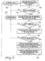
- the obstacle detection system operates as follows.
- the control unit 1 sends selectively an activation pulse to the sensors 2, which start to emit ultrasound signals.
- the sensors 2 start to emit ultrasound signals.
- said obstacles are struck by the waves radiated by the sensors and reflect them, generating an echo, which is received by the sensors 2, as shown schematically in Figure 4 .
- step 105 the microcontroller 4 determines the power to be radiated on the basis of the preceding sensings, acting on the supply voltage in input to the transformer 6.
- the transducer 5 emits ultrasound signals and, in the presence of obstacles 30, receives their reflected signals, i.e., an echo signal.
- step 100 the control unit 1 sends the activation signal cyclically to the sensors 2.
- step 115 the microprocessor 4 of the sensor 2 that detects it determines the possible distance of the obstacle 30 and amplifies the signal adequately according, among other factors, to the determined distance.
- the microcontroller 4 further selects the threshold value with which the amplified signal is to be compared.
- the amplified signal and the adequate threshold value are compared in step 120. If the amplitude of the signal does not exceed the threshold value, the echo signal is ignored (step 125) and the process restarts from step 100, in which the control unit 1 sends an activation pulse to the sensor 2.
- the microcontroller 4 compares, in step 130, the received signal with the signals received in preceding cycles and counts the number of times for which said signal is repeated. If said number of repetitions exceeds a threshold value of the number of cycles (step 135), the sensor 2 sends the calculated distance to the control unit 1.
- the control unit 1 thus activates the signal that warns of the presence of an obstacle 30 and stores in the memory means 10 the value that corresponds to the calculated distance, associating it with the sensor 2 from which it arrives.
- the warning signal may optionally vary according to the distance value sent to the control unit 1.
- step 125 the echo signal is ignored (step 125) and the cycle restarts from step 100 for activating the sensors 2.
- control unit 1 determines, in step 145, the priority of the individual sensors 2, determining a sequence for polling the sensors 2, and adapts the activation cycle accordingly.
- Polling priority is based on the distance detected after the scanning of each sensor 2.
- the distances stored in the memory means 10 are used initially to determine which sensor 2 is detecting the closest obstacle 30.
- the value of the distance that corresponds to the minimum determined distance receives the addition of a priority threshold value, and the new value is stored in the place of the detected minimum distance.
- the sensor thus determined is then granted the priority status and the sensing cycle is adapted so as to poll the prioritized sensor more frequently than the non-prioritized sensors.
- the minimum distance x1 is detected by the sensor S2, which is given priority status.
- the polling cycle according to this particular implementation is therefore S2, S3; S2, S4; S2, S1; S2, S3, and so forth.
- the corresponding sensor 2 If, during successive polling cycles, at least one of the other distances decreases to a value that is lower than the sum of the minimum distance value and the priority threshold value, the corresponding sensor 2 also is given priority status and the obstacle detection sequence is adapted so as to poll all the prioritized sensors more frequently than the non-prioritized sensors.
- One polling that is possible in this case may alternate a non-prioritized sensor with the sequence of prioritized sensors, starting from the sensor that corresponds to the minimum detected distance.
- the polling sequence in this case would be S2, S3, S4; S2, S3, S1; S2; S3; S4, and so forth.
- the described method and system achieve the proposed aim and objects.
- the system thus conceived allows to overcome the limitations of the background art, since the module for eliminating the echo signals detected in succession fewer times than a preset threshold ensures that warning signals are not generated in case of noise sensings, allowing the system to be much more precise in differentiating actual obstacles from incorrect signals.
- the combination of the three modules for the parametric evaluation of the detected signals allows the system to be more flexible in sensings and at the same time more precise.
- the method can be implemented by connecting all the sensors to a single bus and optionally integrating the control unit in another device linked to the CAN network provided in cars.
- This system allows to reduce the number of electronic devices that are present in the car, offering space saving advantages, a consequent reduction of the production costs of said vehicle, and a reduction of power consumption in operation.
- the senor can operate on one or more parameters, such as the time window, radiated power, threshold values and number of repetitions, simultaneously in order to optimize the sensitivity of the sensors.
Landscapes
- Engineering & Computer Science (AREA)
- Radar, Positioning & Navigation (AREA)
- Remote Sensing (AREA)
- Physics & Mathematics (AREA)
- Acoustics & Sound (AREA)
- Computer Networks & Wireless Communication (AREA)
- General Physics & Mathematics (AREA)
- Measurement Of Velocity Or Position Using Acoustic Or Ultrasonic Waves (AREA)
- Traffic Control Systems (AREA)
- Radar Systems Or Details Thereof (AREA)
Claims (12)
- Système pour la détection d'obstacles comprenaitune unité de contrôle (1), estune pluralité de capteurs (2),chacun desdits capteurs (2) comprenant des moyens pour l'émission et la réception (5) pour émettre signaux ultrasons et pour recevoir des signaux d'écho réfléchis par au moins une obstacles (30), etdes moyens d'évaluation (4, 8, 9) pour l'évaluation des signaux d'écho reçus,
où lesdits moyens d'évaluation (4) sont aptes à déterminer, en présence desdits signaux d'écho, la distance possible entre chaque capteur (2) et l'obstacle (30) détecté par lui, et comprend
des moyens (8) aptes à comparer les signaux d'écho reçus avec une valseur de seuil qui dépend de la distance déterminée entre ledit obstacle (30) et ledit capteur (2), et
des moyens (9) aptes à déterminer, à chaque cycle de détection (120, 130, 135), le nombre de fois que les signaux d'écho reçus, dépassants ladite valeur de seuil, se répètent et à ignorer les signaux qui ne se répètent pas un nombre de fois supérieur à un nombre préétabli, et
dans lequel, quand le nombre de fois que chacun desdits signaux dépasse ladite valeur de seuil est supérieur audit nombre préétabli, lesdits moyens de contrôle (1) produisent un signal d'alarme. - Système pour la détection d'obstacles selon la revendication 1, où lesdits moyens d'évaluation (4) comprennent des ultérieurs moyens (6, 7) aptes à régler la puissance irradiée par lesdits moyens d'émission/réception (5).
- Système pour la détection d'obstacles selon l'une ou plusieurs des revendications précédentes, caractérisé en ce que ladite unité de contrôle (1) est apte à gérer lesdits capteurs (2) selon un ordre de priorité.
- Système pour la détection d'obstacles selon l'une ou plusieurs des revendications précédentes, caractérisé en ce que lesdits capteurs (2) sont connectés à ladite unité de contrôle (1) par un BUS unique (3).
- Système pour la détection d'obstacles selon l'une ou plusieurs des revendications précédentes, caractérisé en ce que ladite unité de contrôle (1) comprend des moyens de mémorisation (10) pour mémoriser les valeurs qui indiquent la distance entre ladite pluralité de capteurs (2) et ledit obstacle (30).
- Système pour la détection d'obstacles selon la revendication 5, en dépendance de la revendication 3, caractérisé en ce que ledit ordre de priorité pour la gestion de ladite pluralité de capteurs (2) est déterminé selon lesdites valeurs qui indiquent la distance entre ladite pluralité de capteurs (2) et ledit obstacle (30),
- Système pour la détection d'obstacles utilisant une pluralité de capteurs (2, S1, S2, S3) chacun apte, pendant un cycle de détection, à émettre des signaux à ultrasons et à recevoir des signaux correspondants d'écho réfléchis par au moins un obstacle (30),
comprenant les étapes qui consistent en :a) déterminer pour chaque capteur (2) la puissance que l'on doit irradier, émettre les signaux correspondants à ultrasons, et recevoir les signaux d'écho réfléchis par au moins un desdits obstacles (30) ;b) déterminer (115), selon les signaux d'écho réfléchis, les distances entre les capteurs (2) correspondants et ledit obstacle (30) et amplifier (115) les signaux d'écho reçus selon leurs distances correspondantes ;c) sélectionner, selon les distances déterminées par le point b), des valeurs de seuil avec lesquelles on doit comparer les signaux amplifiés avec lesdites distances déterminées; etd) déterminer (135), à chaque cycles de détection (120, 130, 135), le nombre de fois que les signaux d'écho reçus qui dépassent les respectives valeurs de seuil sélectionnées se répètent, et, si ledit nombre est supérieur à une valeur préétablie, produire (140) un signal d'alarme. - Système pour la détection d'obstacles selon la revendication 7, comprenant aussi les étapes qui consistent en :e) déterminer un ordre de priorité (S2) de chaque capteur (2) en fonction des distances déterminées dans le point b);f) déterminer une séquence d'activation (S2, S3; S2, S4; S2, S1; S2, S3) des capteurs (2) en fonction de l'ordre de priorité déterminé dans le point e); etg) adapter le cycle de détection des capteurs (2) en fonction de la séquence d'activation déterminée dans le point f).
- Système pour la détection d'obstacles selon la revendication 8, caractérisé en ce que le cycle de détection adapté au point g) ne comprend pas, pour un nombre de cycles préétabli qui est supérieur à zéro, les capteurs (2) qui au point a) n'ont pas reçu le signal d'écho.
- Système pour la détection d'obstacles selon une des revendications 8 ou 9, caractérisé en ce que ladite phase de détermination de l'ordre de priorité comprend les étapes qui consistent en:- associer à chaque capteur (2) la valeur de la distance dudit obstacle (30) par lui détectée;- déterminer une valeur correspondante à la plus petite distance détectée et la substituer avec une valeur de seuil de priorité; et- attribuer un état de priorité au capteur (2) qui a détecté ladite plus petite distance.
- Système pour la détection d'obstacles selon la revendication 10, caractérisé en ce que ladite phase de détermination de l'ordre de priorité comprend aussi les étapes qui consistent en:- déterminer à chaque cycle de détection si au moins une des distances détectées est plus petite que la somme de la valeur de la plus petite distance avec la valeur de seuil de priorité; et- attribuer au capteur respectif (2) l'état de priorité en plus des capteurs qui sont déjà en état de priorité.
- Système pour la détection d'obstacles selon la revendication 1, caractérisé en ce que le cycle de détection adapté dans le point g) assure l'activation plus fréquente des capteurs avec un état de priorité par rapport aux capteurs qui ne sont pas dans un état de priorité.
Applications Claiming Priority (1)
| Application Number | Priority Date | Filing Date | Title |
|---|---|---|---|
| IT000244A ITMO20040244A1 (it) | 2004-09-24 | 2004-09-24 | 'sistema e metodo di rilevamento degli ostacoli in particolare per sistemi di agevolazioni del parcheggio di veicoli'. |
Publications (3)
| Publication Number | Publication Date |
|---|---|
| EP1640745A2 EP1640745A2 (fr) | 2006-03-29 |
| EP1640745A3 EP1640745A3 (fr) | 2007-10-03 |
| EP1640745B1 true EP1640745B1 (fr) | 2010-05-05 |
Family
ID=35478417
Family Applications (1)
| Application Number | Title | Priority Date | Filing Date |
|---|---|---|---|
| EP05020425A Not-in-force EP1640745B1 (fr) | 2004-09-24 | 2005-09-20 | Procédé et système de détection d'obstacle, en particulier pour des systèmes pour aider le stationnement des véhicules |
Country Status (5)
| Country | Link |
|---|---|
| US (1) | US7385487B2 (fr) |
| EP (1) | EP1640745B1 (fr) |
| AT (1) | ATE467139T1 (fr) |
| DE (1) | DE602005021035D1 (fr) |
| IT (1) | ITMO20040244A1 (fr) |
Families Citing this family (20)
| Publication number | Priority date | Publication date | Assignee | Title |
|---|---|---|---|---|
| US7724355B1 (en) | 2005-11-29 | 2010-05-25 | Navisense | Method and device for enhancing accuracy in ultrasonic range measurement |
| US20070255498A1 (en) * | 2006-04-28 | 2007-11-01 | Caterpillar Inc. | Systems and methods for determining threshold warning distances for collision avoidance |
| DE102008040905A1 (de) * | 2008-07-31 | 2010-02-04 | Robert Bosch Gmbh | Ultraschallsensor |
| TW201016506A (en) * | 2008-10-21 | 2010-05-01 | Automotive Res & Testing Ct | Parking guidance system and guidance method thereof |
| JP2011133274A (ja) * | 2009-12-22 | 2011-07-07 | Panasonic Electric Works Co Ltd | 車両用障害物監視装置 |
| RU2455659C2 (ru) * | 2010-08-31 | 2012-07-10 | Федеральное государственное бюджетное образовательное учреждение высшего профессионального образования "Нижегородский государственный технический университет им. Р.Е. Алексеева" (НГТУ) | Способ обнаружения двухконтурных параметрических рассеивателей |
| RU2507537C2 (ru) * | 2011-02-15 | 2014-02-20 | Государственное образовательное учреждение высшего профессионального образования "Нижегородский государственный инженерно-экономический институт" | Параметрический рассеиватель - маркер с нелинейным формированием синхросигналов |
| RU2496122C2 (ru) * | 2011-02-15 | 2013-10-20 | Государственное образовательное учреждение высшего профессионального образования "Нижегородский государственный инженерно-экономический институт" | Способ обнаружения одноконтурных параметрических рассеивателей с нелинейным формированием синхронизирующего сигнала |
| RU2487366C2 (ru) * | 2011-07-08 | 2013-07-10 | Государственное образовательное учреждение высшего профессионального образования "Нижегородский государственный инженерно-экономический институт" | Способ обнаружения объектов, маркированных параметрическими рассеивателями |
| US20130057397A1 (en) * | 2011-09-01 | 2013-03-07 | GM Global Technology Operations LLC | Method of operating a vehicle safety system |
| KR101316501B1 (ko) * | 2011-10-14 | 2013-10-10 | 현대자동차주식회사 | 메쉬형 공간 해석기법을 이용한 주차 공간 탐지방법 및 그 시스템 |
| KR101500225B1 (ko) * | 2013-12-18 | 2015-03-06 | 현대자동차주식회사 | 초음파 센서 구동방법 및 구동 장치 |
| JP6340713B2 (ja) * | 2014-03-04 | 2018-06-13 | パナソニックIpマネジメント株式会社 | 障害物検知装置 |
| US9810778B2 (en) | 2015-09-14 | 2017-11-07 | Semiconductor Components Industries, Llc | Triggered-event signaling with digital error reporting |
| DE102015122413B4 (de) * | 2015-12-21 | 2021-12-23 | Valeo Schalter Und Sensoren Gmbh | Verfahren zum Betreiben eines Ultraschallsensors eines Kraftfahrzeugs, Ultraschallsensorvorrichtung, Fahrerassistenzsystem sowie Kraftfahrzeug |
| US9953534B1 (en) * | 2016-10-20 | 2018-04-24 | Ford Global Technologies, Llc | Vehicle collision warnings based on a time-to-collision |
| US11194028B2 (en) | 2017-09-12 | 2021-12-07 | Semiconductor Components Industries, Llc | Measuring resonance parameters of piezoelectric transducers |
| US11269067B2 (en) | 2017-09-12 | 2022-03-08 | Semiconductor Components Industries, Llc | Response-based determination of piezoelectric transducer state |
| CN111367300B (zh) * | 2020-05-27 | 2021-03-23 | 弗徕威智能机器人科技(上海)有限公司 | 多路超声波的障碍检测方法、移动机器人及存储介质 |
| CN113129641B (zh) * | 2021-04-20 | 2022-10-28 | 中国科学院半导体研究所 | 停车位车辆检测装置 |
Family Cites Families (12)
| Publication number | Priority date | Publication date | Assignee | Title |
|---|---|---|---|---|
| JPS58158573A (ja) * | 1982-03-16 | 1983-09-20 | Nippon Denso Co Ltd | 車両用後方障害物検出方法 |
| JPS5977517A (ja) * | 1982-10-27 | 1984-05-04 | Kubota Ltd | 走行車輌 |
| JP2689792B2 (ja) * | 1991-10-30 | 1997-12-10 | 日産自動車株式会社 | 立体音場警報装置 |
| JP3221821B2 (ja) * | 1995-10-20 | 2001-10-22 | ナイルス部品株式会社 | 車両用障害物監視装置 |
| US6087928A (en) * | 1995-10-31 | 2000-07-11 | Breed Automotive Technology, Inc. | Predictive impact sensing system for vehicular safety restraint systems |
| CA2201080C (fr) * | 1996-03-27 | 2000-01-25 | Her Majesty The Queen, In Right Of Canada, As Represented By The Ministe R Of Industry | Systeme de detection ultrason pour assurer la securite des passagers des vehicules motorises |
| DE19655360B4 (de) * | 1996-11-04 | 2010-12-09 | Valeo Schalter Und Sensoren Gmbh | Verfahren und Abstandsmesseinrichtung zur von den Fahrzeugdaten abhängigen Abstandsmessung von Hindernissen |
| JP4028135B2 (ja) * | 1999-05-27 | 2007-12-26 | 本田技研工業株式会社 | 物体検出装置 |
| US6133826A (en) * | 1999-12-07 | 2000-10-17 | Motorola, Inc. | Method and apparatus for detecting objects |
| US6594614B2 (en) * | 2000-04-17 | 2003-07-15 | Delphi Technologies, Inc. | Vehicle back-up aid system |
| US20030122659A1 (en) * | 2001-12-28 | 2003-07-03 | Poron International, Ltd. | Vehicle backup alert system |
| JP2003329773A (ja) * | 2002-05-10 | 2003-11-19 | Hitachi Ltd | 複数の距離検知センサを設置した車両制御装置 |
-
2004
- 2004-09-24 IT IT000244A patent/ITMO20040244A1/it unknown
-
2005
- 2005-09-15 US US11/226,256 patent/US7385487B2/en active Active
- 2005-09-20 DE DE602005021035T patent/DE602005021035D1/de active Active
- 2005-09-20 EP EP05020425A patent/EP1640745B1/fr not_active Not-in-force
- 2005-09-20 AT AT05020425T patent/ATE467139T1/de not_active IP Right Cessation
Also Published As
| Publication number | Publication date |
|---|---|
| US7385487B2 (en) | 2008-06-10 |
| DE602005021035D1 (de) | 2010-06-17 |
| US20060087414A1 (en) | 2006-04-27 |
| ATE467139T1 (de) | 2010-05-15 |
| EP1640745A2 (fr) | 2006-03-29 |
| ITMO20040244A1 (it) | 2004-12-24 |
| EP1640745A3 (fr) | 2007-10-03 |
Similar Documents
| Publication | Publication Date | Title |
|---|---|---|
| EP1640745B1 (fr) | Procédé et système de détection d'obstacle, en particulier pour des systèmes pour aider le stationnement des véhicules | |
| EP1640746B1 (fr) | Procédé et système de détection d'obstacle, en particulier pour des systèmes pour aider le stationnement des véhicules | |
| JP6089585B2 (ja) | 障害物検知装置 | |
| US7248153B2 (en) | Method for parking a vehicle | |
| CN108068800B (zh) | 自动泊车控制系统、探头模块、车辆和自动泊车控制方法 | |
| CN110619764B (zh) | 一种探测障碍物的方法和装置 | |
| US6133826A (en) | Method and apparatus for detecting objects | |
| US7567168B2 (en) | Car reversal radar that automatically modifies the sensor scanning range and method of the same | |
| EP2845028B1 (fr) | Procédé pour faire fonctionner un capteur de distance servant à détecter un environnement | |
| US8823578B2 (en) | Driving assist apparatus | |
| CN113985418A (zh) | 基于超声波雷达的同频干扰信号检测方法、装置和车辆 | |
| EP1591976B1 (fr) | Dispositif de détection d'intrusion dans un espace | |
| KR101509945B1 (ko) | 노이즈로 인한 오인식을 방지할 수 있는 차량의 물체 감지 방법, 및 이를 이용한 주차 보조 시스템의 제어 방법 | |
| JP4628135B2 (ja) | 超音波識別装置、およびこの超音波識別装置を用いた制御装置 | |
| US20220390601A1 (en) | Method for operating a distance sensor of a vehicle in which a transmission signal is adapted in accordance with how an object is classified, computing device, and sensor device | |
| CN113552575A (zh) | 泊车障碍物侦测方法及装置 | |
| KR20160015752A (ko) | 차량 주변의 초근거리 장애물을 감지하는 기능을 갖는 차량용 주차 보조 시스템 및 그 동작 방법 | |
| US10408921B2 (en) | Vehicle detection of external objects | |
| KR19980075630A (ko) | 자동차의 주차보조장치 | |
| CN109799508A (zh) | 车辆盲区监测装置、方法及系统 | |
| CN110967689B (zh) | 一种目标对象高度的确定方法、装置及车载雷达设备 | |
| RU81343U1 (ru) | Устройство для парковки транспортных средств | |
| JPH08292257A (ja) | 超音波センサ | |
| KR200322338Y1 (ko) | 초단파 차량 감지장치 | |
| KR20230130312A (ko) | 차량에 장착되어 주변 물체를 감지하는 물체 감지 장치 및 물체 감지 장치의 제어방법 |
Legal Events
| Date | Code | Title | Description |
|---|---|---|---|
| PUAI | Public reference made under article 153(3) epc to a published international application that has entered the european phase |
Free format text: ORIGINAL CODE: 0009012 |
|
| AK | Designated contracting states |
Kind code of ref document: A2 Designated state(s): AT BE BG CH CY CZ DE DK EE ES FI FR GB GR HU IE IS IT LI LT LU LV MC NL PL PT RO SE SI SK TR |
|
| AX | Request for extension of the european patent |
Extension state: AL BA HR MK YU |
|
| PUAL | Search report despatched |
Free format text: ORIGINAL CODE: 0009013 |
|
| AK | Designated contracting states |
Kind code of ref document: A3 Designated state(s): AT BE BG CH CY CZ DE DK EE ES FI FR GB GR HU IE IS IT LI LT LU LV MC NL PL PT RO SE SI SK TR |
|
| AX | Request for extension of the european patent |
Extension state: AL BA HR MK YU |
|
| 17P | Request for examination filed |
Effective date: 20080325 |
|
| 17Q | First examination report despatched |
Effective date: 20080424 |
|
| AKX | Designation fees paid |
Designated state(s): AT BE BG CH CY CZ DE DK EE ES FI FR GB GR HU IE IS IT LI LT LU LV MC NL PL PT RO SE SI SK TR |
|
| GRAP | Despatch of communication of intention to grant a patent |
Free format text: ORIGINAL CODE: EPIDOSNIGR1 |
|
| GRAJ | Information related to disapproval of communication of intention to grant by the applicant or resumption of examination proceedings by the epo deleted |
Free format text: ORIGINAL CODE: EPIDOSDIGR1 |
|
| GRAP | Despatch of communication of intention to grant a patent |
Free format text: ORIGINAL CODE: EPIDOSNIGR1 |
|
| GRAS | Grant fee paid |
Free format text: ORIGINAL CODE: EPIDOSNIGR3 |
|
| GRAA | (expected) grant |
Free format text: ORIGINAL CODE: 0009210 |
|
| RAP1 | Party data changed (applicant data changed or rights of an application transferred) |
Owner name: META SYSTEM S.P.A. |
|
| AK | Designated contracting states |
Kind code of ref document: B1 Designated state(s): AT BE BG CH CY CZ DE DK EE ES FI FR GB GR HU IE IS IT LI LT LU LV MC NL PL PT RO SE SI SK TR |
|
| REG | Reference to a national code |
Ref country code: GB Ref legal event code: FG4D |
|
| REG | Reference to a national code |
Ref country code: CH Ref legal event code: EP |
|
| REG | Reference to a national code |
Ref country code: IE Ref legal event code: FG4D |
|
| REF | Corresponds to: |
Ref document number: 602005021035 Country of ref document: DE Date of ref document: 20100617 Kind code of ref document: P |
|
| REG | Reference to a national code |
Ref country code: NL Ref legal event code: VDEP Effective date: 20100505 |
|
| LTIE | Lt: invalidation of european patent or patent extension |
Effective date: 20100505 |
|
| PG25 | Lapsed in a contracting state [announced via postgrant information from national office to epo] |
Ref country code: NL Free format text: LAPSE BECAUSE OF FAILURE TO SUBMIT A TRANSLATION OF THE DESCRIPTION OR TO PAY THE FEE WITHIN THE PRESCRIBED TIME-LIMIT Effective date: 20100505 Ref country code: LT Free format text: LAPSE BECAUSE OF FAILURE TO SUBMIT A TRANSLATION OF THE DESCRIPTION OR TO PAY THE FEE WITHIN THE PRESCRIBED TIME-LIMIT Effective date: 20100505 Ref country code: ES Free format text: LAPSE BECAUSE OF FAILURE TO SUBMIT A TRANSLATION OF THE DESCRIPTION OR TO PAY THE FEE WITHIN THE PRESCRIBED TIME-LIMIT Effective date: 20100816 Ref country code: SE Free format text: LAPSE BECAUSE OF FAILURE TO SUBMIT A TRANSLATION OF THE DESCRIPTION OR TO PAY THE FEE WITHIN THE PRESCRIBED TIME-LIMIT Effective date: 20100505 |
|
| PG25 | Lapsed in a contracting state [announced via postgrant information from national office to epo] |
Ref country code: LV Free format text: LAPSE BECAUSE OF FAILURE TO SUBMIT A TRANSLATION OF THE DESCRIPTION OR TO PAY THE FEE WITHIN THE PRESCRIBED TIME-LIMIT Effective date: 20100505 Ref country code: IS Free format text: LAPSE BECAUSE OF FAILURE TO SUBMIT A TRANSLATION OF THE DESCRIPTION OR TO PAY THE FEE WITHIN THE PRESCRIBED TIME-LIMIT Effective date: 20100905 Ref country code: FI Free format text: LAPSE BECAUSE OF FAILURE TO SUBMIT A TRANSLATION OF THE DESCRIPTION OR TO PAY THE FEE WITHIN THE PRESCRIBED TIME-LIMIT Effective date: 20100505 Ref country code: AT Free format text: LAPSE BECAUSE OF FAILURE TO SUBMIT A TRANSLATION OF THE DESCRIPTION OR TO PAY THE FEE WITHIN THE PRESCRIBED TIME-LIMIT Effective date: 20100505 Ref country code: SI Free format text: LAPSE BECAUSE OF FAILURE TO SUBMIT A TRANSLATION OF THE DESCRIPTION OR TO PAY THE FEE WITHIN THE PRESCRIBED TIME-LIMIT Effective date: 20100505 |
|
| PG25 | Lapsed in a contracting state [announced via postgrant information from national office to epo] |
Ref country code: CY Free format text: LAPSE BECAUSE OF FAILURE TO SUBMIT A TRANSLATION OF THE DESCRIPTION OR TO PAY THE FEE WITHIN THE PRESCRIBED TIME-LIMIT Effective date: 20100505 Ref country code: GR Free format text: LAPSE BECAUSE OF FAILURE TO SUBMIT A TRANSLATION OF THE DESCRIPTION OR TO PAY THE FEE WITHIN THE PRESCRIBED TIME-LIMIT Effective date: 20100806 Ref country code: PL Free format text: LAPSE BECAUSE OF FAILURE TO SUBMIT A TRANSLATION OF THE DESCRIPTION OR TO PAY THE FEE WITHIN THE PRESCRIBED TIME-LIMIT Effective date: 20100505 |
|
| PG25 | Lapsed in a contracting state [announced via postgrant information from national office to epo] |
Ref country code: DK Free format text: LAPSE BECAUSE OF FAILURE TO SUBMIT A TRANSLATION OF THE DESCRIPTION OR TO PAY THE FEE WITHIN THE PRESCRIBED TIME-LIMIT Effective date: 20100505 Ref country code: EE Free format text: LAPSE BECAUSE OF FAILURE TO SUBMIT A TRANSLATION OF THE DESCRIPTION OR TO PAY THE FEE WITHIN THE PRESCRIBED TIME-LIMIT Effective date: 20100505 Ref country code: PT Free format text: LAPSE BECAUSE OF FAILURE TO SUBMIT A TRANSLATION OF THE DESCRIPTION OR TO PAY THE FEE WITHIN THE PRESCRIBED TIME-LIMIT Effective date: 20100906 |
|
| PG25 | Lapsed in a contracting state [announced via postgrant information from national office to epo] |
Ref country code: RO Free format text: LAPSE BECAUSE OF FAILURE TO SUBMIT A TRANSLATION OF THE DESCRIPTION OR TO PAY THE FEE WITHIN THE PRESCRIBED TIME-LIMIT Effective date: 20100505 Ref country code: BE Free format text: LAPSE BECAUSE OF FAILURE TO SUBMIT A TRANSLATION OF THE DESCRIPTION OR TO PAY THE FEE WITHIN THE PRESCRIBED TIME-LIMIT Effective date: 20100505 Ref country code: SK Free format text: LAPSE BECAUSE OF FAILURE TO SUBMIT A TRANSLATION OF THE DESCRIPTION OR TO PAY THE FEE WITHIN THE PRESCRIBED TIME-LIMIT Effective date: 20100505 Ref country code: CZ Free format text: LAPSE BECAUSE OF FAILURE TO SUBMIT A TRANSLATION OF THE DESCRIPTION OR TO PAY THE FEE WITHIN THE PRESCRIBED TIME-LIMIT Effective date: 20100505 |
|
| PLBE | No opposition filed within time limit |
Free format text: ORIGINAL CODE: 0009261 |
|
| STAA | Information on the status of an ep patent application or granted ep patent |
Free format text: STATUS: NO OPPOSITION FILED WITHIN TIME LIMIT |
|
| 26N | No opposition filed |
Effective date: 20110208 |
|
| PG25 | Lapsed in a contracting state [announced via postgrant information from national office to epo] |
Ref country code: MC Free format text: LAPSE BECAUSE OF NON-PAYMENT OF DUE FEES Effective date: 20100930 |
|
| REG | Reference to a national code |
Ref country code: CH Ref legal event code: PL |
|
| REG | Reference to a national code |
Ref country code: DE Ref legal event code: R097 Ref document number: 602005021035 Country of ref document: DE Effective date: 20110207 |
|
| PG25 | Lapsed in a contracting state [announced via postgrant information from national office to epo] |
Ref country code: LI Free format text: LAPSE BECAUSE OF NON-PAYMENT OF DUE FEES Effective date: 20100930 Ref country code: CH Free format text: LAPSE BECAUSE OF NON-PAYMENT OF DUE FEES Effective date: 20100930 Ref country code: IE Free format text: LAPSE BECAUSE OF NON-PAYMENT OF DUE FEES Effective date: 20100920 |
|
| PG25 | Lapsed in a contracting state [announced via postgrant information from national office to epo] |
Ref country code: LU Free format text: LAPSE BECAUSE OF NON-PAYMENT OF DUE FEES Effective date: 20100920 Ref country code: BG Free format text: LAPSE BECAUSE OF FAILURE TO SUBMIT A TRANSLATION OF THE DESCRIPTION OR TO PAY THE FEE WITHIN THE PRESCRIBED TIME-LIMIT Effective date: 20100505 Ref country code: HU Free format text: LAPSE BECAUSE OF FAILURE TO SUBMIT A TRANSLATION OF THE DESCRIPTION OR TO PAY THE FEE WITHIN THE PRESCRIBED TIME-LIMIT Effective date: 20101106 |
|
| PG25 | Lapsed in a contracting state [announced via postgrant information from national office to epo] |
Ref country code: TR Free format text: LAPSE BECAUSE OF FAILURE TO SUBMIT A TRANSLATION OF THE DESCRIPTION OR TO PAY THE FEE WITHIN THE PRESCRIBED TIME-LIMIT Effective date: 20100505 |
|
| PG25 | Lapsed in a contracting state [announced via postgrant information from national office to epo] |
Ref country code: BG Free format text: LAPSE BECAUSE OF FAILURE TO SUBMIT A TRANSLATION OF THE DESCRIPTION OR TO PAY THE FEE WITHIN THE PRESCRIBED TIME-LIMIT Effective date: 20100805 |
|
| REG | Reference to a national code |
Ref country code: FR Ref legal event code: PLFP Year of fee payment: 11 |
|
| REG | Reference to a national code |
Ref country code: FR Ref legal event code: CA Effective date: 20160523 |
|
| REG | Reference to a national code |
Ref country code: FR Ref legal event code: PLFP Year of fee payment: 12 |
|
| REG | Reference to a national code |
Ref country code: FR Ref legal event code: PLFP Year of fee payment: 13 |
|
| REG | Reference to a national code |
Ref country code: FR Ref legal event code: PLFP Year of fee payment: 14 |
|
| PGFP | Annual fee paid to national office [announced via postgrant information from national office to epo] |
Ref country code: IT Payment date: 20210920 Year of fee payment: 17 Ref country code: FR Payment date: 20210927 Year of fee payment: 17 |
|
| PGFP | Annual fee paid to national office [announced via postgrant information from national office to epo] |
Ref country code: GB Payment date: 20210927 Year of fee payment: 17 Ref country code: DE Payment date: 20210929 Year of fee payment: 17 |
|
| REG | Reference to a national code |
Ref country code: DE Ref legal event code: R119 Ref document number: 602005021035 Country of ref document: DE |
|
| GBPC | Gb: european patent ceased through non-payment of renewal fee |
Effective date: 20220920 |
|
| PG25 | Lapsed in a contracting state [announced via postgrant information from national office to epo] |
Ref country code: FR Free format text: LAPSE BECAUSE OF NON-PAYMENT OF DUE FEES Effective date: 20220930 Ref country code: DE Free format text: LAPSE BECAUSE OF NON-PAYMENT OF DUE FEES Effective date: 20230401 |
|
| PG25 | Lapsed in a contracting state [announced via postgrant information from national office to epo] |
Ref country code: IT Free format text: LAPSE BECAUSE OF NON-PAYMENT OF DUE FEES Effective date: 20220920 Ref country code: GB Free format text: LAPSE BECAUSE OF NON-PAYMENT OF DUE FEES Effective date: 20220920 |