EP1640745B1 - Obstacle detection method and system, particularly for systems for assisting the parking of vehicles - Google Patents
Obstacle detection method and system, particularly for systems for assisting the parking of vehicles Download PDFInfo
- Publication number
- EP1640745B1 EP1640745B1 EP05020425A EP05020425A EP1640745B1 EP 1640745 B1 EP1640745 B1 EP 1640745B1 EP 05020425 A EP05020425 A EP 05020425A EP 05020425 A EP05020425 A EP 05020425A EP 1640745 B1 EP1640745 B1 EP 1640745B1
- Authority
- EP
- European Patent Office
- Prior art keywords
- sensors
- obstacle
- priority
- signals
- obstacle detection
- Prior art date
- Legal status (The legal status is an assumption and is not a legal conclusion. Google has not performed a legal analysis and makes no representation as to the accuracy of the status listed.)
- Not-in-force
Links
Images


Classifications
-
- G—PHYSICS
- G01—MEASURING; TESTING
- G01S—RADIO DIRECTION-FINDING; RADIO NAVIGATION; DETERMINING DISTANCE OR VELOCITY BY USE OF RADIO WAVES; LOCATING OR PRESENCE-DETECTING BY USE OF THE REFLECTION OR RERADIATION OF RADIO WAVES; ANALOGOUS ARRANGEMENTS USING OTHER WAVES
- G01S15/00—Systems using the reflection or reradiation of acoustic waves, e.g. sonar systems
- G01S15/88—Sonar systems specially adapted for specific applications
- G01S15/93—Sonar systems specially adapted for specific applications for anti-collision purposes
- G01S15/931—Sonar systems specially adapted for specific applications for anti-collision purposes of land vehicles
- G01S2015/932—Sonar systems specially adapted for specific applications for anti-collision purposes of land vehicles for parking operations
Abstract
Description
- The present invention relates to an obstacle detection method and system, particularly for systems designed to facilitate the parking of motor vehicles.
- During maneuvers for parking a vehicle, it is not possible to perceive exactly the distance between the vehicle and the obstacles that lie in the parking area, particularly during reversing maneuvers or maneuvers for approach on the opposite side with respect to the driver. Moreover, it is not infrequent to find oneself in a condition in which some obstacles are completely concealed and invisible to the driver, as occurs in the case of obstacles located in corners that are covered by the vehicle structure or are very low, for example the typical bollards used to delimit parking areas, or simple poles.
- In order to solve the drawback and thus avoid unpleasant accidents, systems are known which are provided with sensors for detecting the distance between the motor vehicle and the surrounding obstacles.
- Systems using ultrasonic sensors are mainly used for measuring the distance between an obstacle and a motor vehicle; these sensors detect a signal emitted previously by a radiating element located in the vicinity of the sensor and reflected by an obstacle that lies proximate to the vehicle.
- During an adequate time window, the received return signal, known as echo signal, is compared with a threshold value, and if said threshold value is exceeded, the sensor generates a warning signal.
- In these systems, it is particularly important to avoid the emission of incorrect warning signals and to increase the precision of the assisted parking system. Incorrect warning signals refer in particular to signals reflected by objects that do not constitute a danger of collision with the vehicle, such as for example the ground, the optional towing hook mounted on the vehicle, particularly distant obstacles, or signals caused by noise.
- For this purpose, currently it is known to adjust the time window so as to exclude from the comparison with the threshold values the signals caused by particularly distant obstacles. The duration of the time window in fact determines the monitoring depth of the system.
- As an alternative, it is common to vary the duration of the signals emitted by the radiating element of the sensor or to vary the power radiated by said signals.
- Finally, it is also known to act on the threshold values, which can vary according to time. Generally, the threshold values are reduced monotonically over time until the end of the time window, in order to prevent the system from generating warning signals caused by extremely proximate signals produced by the reflection of the ultrasound for example against the ground or against the towing hook.
- Other known systems adapt the threshold values to the physical parameters of the car in order to further increase the precision of the system. Moreover, these threshold values are changed dynamically also according to the direction of travel of the vehicle, so as to increase the sensitivity of the sensors located in the direction of travel and reduce the sensitivity of the remaining ones.
- The need to detect the various obstacles that are present around the vehicle and to take into account the various factors described above in order to provide increasingly accurate information is a requirement that still stands despite the existing solutions.
- In particular, one of the problems that most significantly affect the sensing devices of the background art is reliability, i.e., the assurance that the warning signals are emitted exclusively at an obstacle. For this purpose, it is necessary to avoid the emission of incorrect warning signals caused by noise, which may confuse the driver, and therefore increase the precision and reliability of the system.
- From document
US 6.087.928 it is known a safety system for a motor vehicle including a processor for predicting the collision of an obstacle with the motor vehicle and for activating in reply various safety devices, such as a seat belt and an air bag, wherein the processor receives the output of a plurality of sensors including a radar microwave wave system for generating and propagating electromagnetic radiation waves and suitable to receive reflected waves. - It is also known from
DE 196 45 339 A1 an ultrasound parking aid system which emits warning signals when an echo signal lying within an audibility window exceeds a given threshold value, wherein the sensitivity of the system can be adapted to fixed data of the vehicle and/or the carriageway. - However even the solutions disclosed by the above documents appear to require further improvements in order to detect in a more sure and precise way the presence of obstacles, so as to avoid in particular the generation of wrong warning signals.
- The aim of the present invention is to eliminate the drawbacks mentioned above in known types of obstacle detection system, by providing an obstacle detection system that minimizes the emission of incorrect warning signals and thus increases the precision of said system.
- Within this aim, an object of the present invention is to provide an obstacle detection system that is capable of adapting the sensitivity of the sensors to physical and environmental parameters and to the arrangement of the obstacles.
- Another object of the present invention is to provide an obstacle detection system that is more flexible and optimized.
- Another object of the present invention is to provide an obstacle detection system that requires a reduced number of electronic components for its operation.
- This aim and these and other objects, which will become better apparent from the description that follows, are achieved by an obstacle detection system, which comprises a control unit and a plurality of sensors, said sensors comprising means for emitting an ultrasonic signal and for receiving an echo signal reflected by at least one obstacle and means for the parametric evaluation of received echo signals, characterized in that the means for parametric evaluation comprise means suitable to determine, for each sensing, the number of times for which the received signals are repeated and to reject the signals that are repeated for a number of times that is lower than a preset number.
- Conveniently, the parametric evaluation means further comprise means suitable to drive the power radiated by the signal emission means and means suitable to compare the signals received by the echo signal receiving means with threshold values.
- The proposed aim and objects are also achieved by an obstacle detection method, which comprises the steps of determining, for each sensor that belongs to the activation cycle, the power to be radiated, emitting the corresponding ultrasonic signals, and receiving the echo signals reflected by at least one obstacle; determining, on the basis of the received echo signals, the distances of the corresponding sensors from the obstacle and amplifying the received echo signals according to their corresponding distances; selecting the threshold values with which the amplified signals according to the determined distances are to be compared; and is characterized in that it comprises the step of determining, for each sensing cycle, the number of times for which the signals that exceed the respective selected threshold values are repeated and, if said number is greater than a preset value, generating a warning signal.
- Conveniently, the obstacle detection method further comprises the steps of: determining the order of priority of the individual sensors according to the calculated distances; determining the activation sequence of the sensors according to the determined order of priority; and adapting the sensor activation cycle according to the determined activation sequence.
- Further characteristics and advantages of the invention will become better apparent from the following detailed description of a preferred but not exclusive embodiment of the obstacle detection system, illustrated by way of non-limiting example in the accompanying drawings, wherein:
-
Figure 1 is a schematic view of the architecture of the system according to the invention; -
Figure 2 is a more detailed diagram of the sensors ofFigure 1 ; -
Figure 3 is a block diagram of the sensor used in the system according to the invention; -
Figure 4 is a schematic view of a scenario in which a sensor detects an obstacle; -
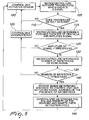
Figure 5 is a block diagram of the management of each individual sensor; -
Figure 6 is a schematic view of a particular scenario in which different sensors detect different distances from one or more obstacles. - As shown schematically in
Figure 1 , the obstacle detection system comprises a control unit 1, which is suitable to manage a variable number ofsensors 2 connected to the control unit 1 by means of at least onebus 3 and comprises memory means 10. The control unit 1 may optionally be integrated in devices that already exist within the motor vehicle and are connected to the internal network, typically of the CAN type, of the car. - The
sensors 2 comprise parametric evaluation means, such as amicrocontroller 4 for driving signal emission means and such signal emission means formed by atransducer 5 capable of emitting and receiving ultrasound. - For this purpose, the
microcontroller 4 comprises power driving means, such as amodule 7 for driving the power of the signal radiated by the signal emission means, such as thetransducer 5 by varying the number of pulses sent to thetransducer 5 and the supply voltage. Moreover, the transducer receives from the microcontroller 4 a signal which determines the time window for listening for the echo signal. - In order to emit the ultrasound signal, the supply voltage reaches the
transducer 5 across atransformer 6, which raises in its peak-to-peak value according to the driving of themicrocontroller 4. - Further, the
microcontroller 4 comprises comparison means, such as amodule 8 for comparing the reflected signal with dynamically optimized threshold values. Themodule 8 further amplifies adequately the received echo signal before performing the comparison. - Moreover, the
microcontroller 4 comprises polling means, such as a filter module 9, which is suitable to eliminate echo signals detected in succession a number of times that is smaller than a preset threshold. The filter module 9 recognizes false reports, caused for example by noise, on the basis of the number of repeated sensings; only echo signals that are repeated for a sufficient number of times are interpreted as signals that indicate obstacles and are then subjected to comparison by means of thecomparison module 8. - The
modules modules - The obstacle detection system operates as follows.
- When the system is activated (
step 100 ofFigure 5 ), the control unit 1 sends selectively an activation pulse to thesensors 2, which start to emit ultrasound signals. During the movement of thevehicle 20 toward anyobstacles 30, said obstacles are struck by the waves radiated by the sensors and reflect them, generating an echo, which is received by thesensors 2, as shown schematically inFigure 4 . - In detail, in
step 105 themicrocontroller 4 determines the power to be radiated on the basis of the preceding sensings, acting on the supply voltage in input to thetransformer 6. Depending on said supply voltage, thetransducer 5 emits ultrasound signals and, in the presence ofobstacles 30, receives their reflected signals, i.e., an echo signal. - If no echo signal is received, the sensing process restarts from
step 100, in which the control unit 1 sends the activation signal cyclically to thesensors 2. - If instead there is an echo signal, in
step 115 themicroprocessor 4 of thesensor 2 that detects it determines the possible distance of theobstacle 30 and amplifies the signal adequately according, among other factors, to the determined distance. - Depending on the calculated distance, the
microcontroller 4 further selects the threshold value with which the amplified signal is to be compared. The amplified signal and the adequate threshold value are compared instep 120. If the amplitude of the signal does not exceed the threshold value, the echo signal is ignored (step 125) and the process restarts fromstep 100, in which the control unit 1 sends an activation pulse to thesensor 2. - If instead the amplitude of the signal exceeds the threshold value, the
microcontroller 4 compares, instep 130, the received signal with the signals received in preceding cycles and counts the number of times for which said signal is repeated. If said number of repetitions exceeds a threshold value of the number of cycles (step 135), thesensor 2 sends the calculated distance to the control unit 1. The control unit 1 thus activates the signal that warns of the presence of anobstacle 30 and stores in the memory means 10 the value that corresponds to the calculated distance, associating it with thesensor 2 from which it arrives. The warning signal may optionally vary according to the distance value sent to the control unit 1. - In a negative case, instead, the echo signal is ignored (step 125) and the cycle restarts from
step 100 for activating thesensors 2. - Depending on the values of the distance of the
obstacles 30 from theindividual sensors 2 received by the control unit 1, the control unit 1 determines, instep 145, the priority of theindividual sensors 2, determining a sequence for polling thesensors 2, and adapts the activation cycle accordingly. - Polling priority is based on the distance detected after the scanning of each
sensor 2. The distances stored in the memory means 10 are used initially to determine whichsensor 2 is detecting theclosest obstacle 30. The value of the distance that corresponds to the minimum determined distance receives the addition of a priority threshold value, and the new value is stored in the place of the detected minimum distance. - The sensor thus determined is then granted the priority status and the sensing cycle is adapted so as to poll the prioritized sensor more frequently than the non-prioritized sensors.
- For example, it is possible to alternate the polling of the prioritized sensor with a non-prioritized sensor, as shown in
Figure 6 . - In the particular example of
Figure 6 , the minimum distance x1 is detected by the sensor S2, which is given priority status. The polling cycle according to this particular implementation is therefore S2, S3; S2, S4; S2, S1; S2, S3, and so forth. - If, during successive polling cycles, at least one of the other distances decreases to a value that is lower than the sum of the minimum distance value and the priority threshold value, the corresponding
sensor 2 also is given priority status and the obstacle detection sequence is adapted so as to poll all the prioritized sensors more frequently than the non-prioritized sensors. - Again with reference to the example of
Figure 6 , if the distance x2 decreases below the sum of the minimum distance value and the priority threshold value, then S3 also obtains priority status. - One polling that is possible in this case may alternate a non-prioritized sensor with the sequence of prioritized sensors, starting from the sensor that corresponds to the minimum detected distance. The polling sequence in this case would be S2, S3, S4; S2, S3, S1; S2; S3; S4, and so forth.
- In an alternative embodiment, it might also be possible to exclude from the polling, for a preset number of cycles, the sensors that initially have detected no signal. In this manner, the number of sensors activated at each cycle is reduced, thus reducing the time between two successive pollings of the sensors that detect an obstacle.
- It has thus been shown that the described method and system achieve the proposed aim and objects. In particular, it has been found that the system thus conceived allows to overcome the limitations of the background art, since the module for eliminating the echo signals detected in succession fewer times than a preset threshold ensures that warning signals are not generated in case of noise sensings, allowing the system to be much more precise in differentiating actual obstacles from incorrect signals.
- Further, the combination of the three modules for the parametric evaluation of the detected signals allows the system to be more flexible in sensings and at the same time more precise.
- Moreover, it has been found that the method can be implemented by connecting all the sensors to a single bus and optionally integrating the control unit in another device linked to the CAN network provided in cars. This system allows to reduce the number of electronic devices that are present in the car, offering space saving advantages, a consequent reduction of the production costs of said vehicle, and a reduction of power consumption in operation.
- Further, the fact that parametric evaluation occurs within the sensors and is not centralized in the control unit allows the system to be much faster during the evaluation step.
- Clearly, numerous modifications are evident and can be performed promptly by the person skilled in the art without abandoning the scope of the protection of the appended claims. For example, it is obvious for the person skilled in the art that the switch of the sensor can be provided in any manner, for example by means of any type of transistor.
- Likewise, it is evident to the person skilled in the art that the sensor can operate on one or more parameters, such as the time window, radiated power, threshold values and number of repetitions, simultaneously in order to optimize the sensitivity of the sensors.
- Therefore, the scope of the protection of the claims must not be limited by the illustrations or by the preferred embodiments described by way of example, but rather the claims must comprise all the characteristics of the present invention.
- Where technical features mentioned in any claim are followed by reference signs, those reference signs have been included for the sole purpose of increasing the intelligibility or the claims and accordingly such reference signs do not have any limiting effect on the interpretation of each element identified by way of example by such reference signs.
Claims (12)
- An obstacle detection system, comprisinga control unit (1), anda plurality of sensors (2),each of said sensors, (2) comprising emitting/receiving means (5) for emitting ultrasonic signals and for receiving echo signals reflected by at least one obstacle (30), andevaluation means (4, 8, 9) for the evaluation of the received echo signals,wherein said evaluation means (4) are suitable to determined, in presence of said echo signals, the possible distance between each sensor (2) and the obstacle (30) detected by it, and comprisemeans (8) suitable to compare the received echo signals with a threshold value depending on the determined distance of said obstacle (30) from the sensor (2), andmeans (9) suitable to determine, at each sensing cycle (120, 130, 135), the number of times for which the received echo signals, exceeding said threshold value, are repeated and to ignore the signals that are not repeated for a number of times that is greater than a preset number, andwherein, when the number of times for which said signals exceeding said threshold value is greater than said preset number, said control means (1) generate a warning signal.
- The obstacle detection system according to claim 1, wherein said evaluation means (4) further comprise means (6, 7) suitable to drive the power radiated by said signal emitting/receiving means (5).
- The obstacle detection system according to any one of the preceding claims, characterized in that said control unit (1) is suitable to manage said sensors (2) according to an order of priority.
- The obstacle detection system according to any one of the preceding claims, characterized in that said sensors (2) are connected to said control unit (1) by means of a single bus (3).
- The obstacle detection system according to one of the preceding claims, characterized in that said control unit (1) comprises memory means (10) for storing values that indicate the distance between said plurality of sensors (2) and said obstacle (30).
- The obstacle detection system according to claim 5, as dependent on claim 3, characterized in that said order of priority for the management of said plurality or sensors (2) is determined according to said values that indicate the distance between said plurality of sensors (2) and said obstacle (30).
- A method for the detection of obstacles by using a plurality of sensors (2, S1, S2, S3) each suitable, during a sensing cycle, for emitting ultrasonic signals and for receiving corresponding echo signals reflected by at least one obstacle (30),
comprising the steps of:a) for each sensor (2) determining the power to be radiated, emitting the corresponding ultrasound signals, and receiving the echo signals reflected by said at least one obstacle (30);b) depending on the echo signals received, determining (115) the distances of the corresponding sensors (2) from said obstacle (30) and amplifying (115) the received echo signals according to their corresponding distances;c) depending on the distances determined in step b), selecting the threshold values with which the signals amplified according to such determined distances are to be compared; andd) determining (135), at each sensing cycle (120, 130, 135), the number of times for which the received echo signals that exceed the respective selected threshold values are repeated, and, if said number is higher than a preset value, generating (140) a warning signal. - The obstacle detection method according to claim 7, wherein it further comprises the steps of:e) determining an order of priority (S2) of the individual sensors (2) according to the distances determined in step b);f) determining an activation sequence (S2, S3; S2, S4; S2, S1; S2, S3) of the sensors (2) according to the order of priority determined in step e); andg) adapting the sensing cycle of the sensors (2) according to the activation sequence determined in step f).
- The obstacle detection method according to claim 8, characterized in that the sensing cycle adapted in step g) does not comprise, for a preset number of cycles that is greater than zero, the sensors (2) that in step a) have not received an echo signal.
- The obstacle detection method according to one of claims 8 or 9, characterized in that said step of determining the order of priority comprises the steps of:- associating with each sensor (2) the value of the distance from said obstacle (30) detected by it;- determining a value that corresponds to the minimum detected distance and replacing it with a value equal to the sum of said minimum distance value and of a priority threshold value; and- assigning to the sensor (2) that detected said minimum distance a priority status.
- The obstacle detection method according to claim 10, characterized in that said step for determining the order of priority further comprises the steps of:- at each sensing cycle, determining whether at least one of the measured distances is shorter than the sum of the minimum distance value and the priority threshold value; and- assigning to the respective sensor (2) the priority status in addition to the sensors that already have a priority status.
- The obstacle detection method according to claim 11, characterized in that the sensing cycle adapted in step g) provides for the more frequent activation of the sensors having a priority status with respect to the sensors that do not have a priority status.
Applications Claiming Priority (1)
| Application Number | Priority Date | Filing Date | Title |
|---|---|---|---|
| IT000244A ITMO20040244A1 (en) | 2004-09-24 | 2004-09-24 | 'OBSTACLE DETECTION SYSTEM AND METHOD IN PARTICULAR FOR VEHICLE PARKING FACILITIES'. |
Publications (3)
| Publication Number | Publication Date |
|---|---|
| EP1640745A2 EP1640745A2 (en) | 2006-03-29 |
| EP1640745A3 EP1640745A3 (en) | 2007-10-03 |
| EP1640745B1 true EP1640745B1 (en) | 2010-05-05 |
Family
ID=35478417
Family Applications (1)
| Application Number | Title | Priority Date | Filing Date |
|---|---|---|---|
| EP05020425A Not-in-force EP1640745B1 (en) | 2004-09-24 | 2005-09-20 | Obstacle detection method and system, particularly for systems for assisting the parking of vehicles |
Country Status (5)
| Country | Link |
|---|---|
| US (1) | US7385487B2 (en) |
| EP (1) | EP1640745B1 (en) |
| AT (1) | ATE467139T1 (en) |
| DE (1) | DE602005021035D1 (en) |
| IT (1) | ITMO20040244A1 (en) |
Families Citing this family (20)
| Publication number | Priority date | Publication date | Assignee | Title |
|---|---|---|---|---|
| US7724355B1 (en) | 2005-11-29 | 2010-05-25 | Navisense | Method and device for enhancing accuracy in ultrasonic range measurement |
| US20070255498A1 (en) * | 2006-04-28 | 2007-11-01 | Caterpillar Inc. | Systems and methods for determining threshold warning distances for collision avoidance |
| DE102008040905A1 (en) * | 2008-07-31 | 2010-02-04 | Robert Bosch Gmbh | ultrasonic sensor |
| TW201016506A (en) * | 2008-10-21 | 2010-05-01 | Automotive Res & Testing Ct | Parking guidance system and guidance method thereof |
| JP2011133274A (en) * | 2009-12-22 | 2011-07-07 | Panasonic Electric Works Co Ltd | Obstacle monitoring device for vehicle |
| RU2455659C2 (en) * | 2010-08-31 | 2012-07-10 | Федеральное государственное бюджетное образовательное учреждение высшего профессионального образования "Нижегородский государственный технический университет им. Р.Е. Алексеева" (НГТУ) | Method of detecting double-loop parametric scatterers |
| RU2507537C2 (en) * | 2011-02-15 | 2014-02-20 | Государственное образовательное учреждение высшего профессионального образования "Нижегородский государственный инженерно-экономический институт" | Parametric scatterer-marker with nonlinear clock signal generation |
| RU2496122C2 (en) * | 2011-02-15 | 2013-10-20 | Государственное образовательное учреждение высшего профессионального образования "Нижегородский государственный инженерно-экономический институт" | Method of detecting single-loop parametric scatterers with nonlinear generation of synchronising signal |
| RU2487366C2 (en) * | 2011-07-08 | 2013-07-10 | Государственное образовательное учреждение высшего профессионального образования "Нижегородский государственный инженерно-экономический институт" | Method of detecting objects labelled with parametric scatterers |
| US20130057397A1 (en) * | 2011-09-01 | 2013-03-07 | GM Global Technology Operations LLC | Method of operating a vehicle safety system |
| KR101316501B1 (en) * | 2011-10-14 | 2013-10-10 | 현대자동차주식회사 | Parking area detection system and method thereof using mesh space analysis |
| KR101500225B1 (en) * | 2013-12-18 | 2015-03-06 | 현대자동차주식회사 | A driving method of the ultra sonic sensor and the apparatus thereof |
| JP6340713B2 (en) * | 2014-03-04 | 2018-06-13 | パナソニックIpマネジメント株式会社 | Obstacle detection device |
| US9810778B2 (en) | 2015-09-14 | 2017-11-07 | Semiconductor Components Industries, Llc | Triggered-event signaling with digital error reporting |
| DE102015122413B4 (en) * | 2015-12-21 | 2021-12-23 | Valeo Schalter Und Sensoren Gmbh | Method for operating an ultrasonic sensor of a motor vehicle, ultrasonic sensor device, driver assistance system and motor vehicle |
| US9953534B1 (en) * | 2016-10-20 | 2018-04-24 | Ford Global Technologies, Llc | Vehicle collision warnings based on a time-to-collision |
| US11194028B2 (en) | 2017-09-12 | 2021-12-07 | Semiconductor Components Industries, Llc | Measuring resonance parameters of piezoelectric transducers |
| US11269067B2 (en) | 2017-09-12 | 2022-03-08 | Semiconductor Components Industries, Llc | Response-based determination of piezoelectric transducer state |
| CN111367300B (en) * | 2020-05-27 | 2021-03-23 | 弗徕威智能机器人科技(上海)有限公司 | Obstacle detection method for multi-path ultrasonic waves, mobile robot, and storage medium |
| CN113129641B (en) * | 2021-04-20 | 2022-10-28 | 中国科学院半导体研究所 | Parking space vehicle detection device |
Family Cites Families (12)
| Publication number | Priority date | Publication date | Assignee | Title |
|---|---|---|---|---|
| JPS58158573A (en) * | 1982-03-16 | 1983-09-20 | Nippon Denso Co Ltd | Detection of backward obstacle for vehicle |
| JPS5977517A (en) * | 1982-10-27 | 1984-05-04 | Kubota Ltd | Running vehicle |
| JP2689792B2 (en) * | 1991-10-30 | 1997-12-10 | 日産自動車株式会社 | Three-dimensional sound field alarm device |
| JP3221821B2 (en) * | 1995-10-20 | 2001-10-22 | ナイルス部品株式会社 | Obstacle monitoring device for vehicles |
| US6087928A (en) * | 1995-10-31 | 2000-07-11 | Breed Automotive Technology, Inc. | Predictive impact sensing system for vehicular safety restraint systems |
| CA2201080C (en) * | 1996-03-27 | 2000-01-25 | Her Majesty The Queen, In Right Of Canada, As Represented By The Ministe R Of Industry | Ultrasonic detection system for safety of vehicle passengers |
| DE19655360B4 (en) * | 1996-11-04 | 2010-12-09 | Valeo Schalter Und Sensoren Gmbh | Method and distance measuring device for the distance measurement of obstacles dependent on the vehicle data |
| JP4028135B2 (en) * | 1999-05-27 | 2007-12-26 | 本田技研工業株式会社 | Object detection device |
| US6133826A (en) * | 1999-12-07 | 2000-10-17 | Motorola, Inc. | Method and apparatus for detecting objects |
| US6594614B2 (en) * | 2000-04-17 | 2003-07-15 | Delphi Technologies, Inc. | Vehicle back-up aid system |
| US20030122659A1 (en) * | 2001-12-28 | 2003-07-03 | Poron International, Ltd. | Vehicle backup alert system |
| JP2003329773A (en) * | 2002-05-10 | 2003-11-19 | Hitachi Ltd | Vehicle control apparatus with a plurality of distance detecting sensor installed |
-
2004
- 2004-09-24 IT IT000244A patent/ITMO20040244A1/en unknown
-
2005
- 2005-09-15 US US11/226,256 patent/US7385487B2/en active Active
- 2005-09-20 EP EP05020425A patent/EP1640745B1/en not_active Not-in-force
- 2005-09-20 AT AT05020425T patent/ATE467139T1/en not_active IP Right Cessation
- 2005-09-20 DE DE602005021035T patent/DE602005021035D1/en active Active
Also Published As
| Publication number | Publication date |
|---|---|
| DE602005021035D1 (en) | 2010-06-17 |
| EP1640745A3 (en) | 2007-10-03 |
| ITMO20040244A1 (en) | 2004-12-24 |
| EP1640745A2 (en) | 2006-03-29 |
| US20060087414A1 (en) | 2006-04-27 |
| US7385487B2 (en) | 2008-06-10 |
| ATE467139T1 (en) | 2010-05-15 |
Similar Documents
| Publication | Publication Date | Title |
|---|---|---|
| EP1640745B1 (en) | Obstacle detection method and system, particularly for systems for assisting the parking of vehicles | |
| EP1640746B1 (en) | Obstacle detection method and system, particularly for systems for assisting the parking of vehicles | |
| JP6089585B2 (en) | Obstacle detection device | |
| US7248153B2 (en) | Method for parking a vehicle | |
| CN108068800B (en) | Automatic parking control system, probe module, vehicle and automatic parking control method | |
| CN110619764B (en) | Method and device for detecting obstacle | |
| US6133826A (en) | Method and apparatus for detecting objects | |
| US7567168B2 (en) | Car reversal radar that automatically modifies the sensor scanning range and method of the same | |
| EP1791730A1 (en) | Device for detecting a collision between a vehicle and an obstacle | |
| EP2845028B1 (en) | Method for operating a distance sensor for detecting surroundings | |
| US8823578B2 (en) | Driving assist apparatus | |
| CN113985418A (en) | Same-frequency interference signal detection method and device based on ultrasonic radar and vehicle | |
| EP1591976B1 (en) | Intrusion detection device for spaces | |
| KR101509945B1 (en) | Object detection method of vehicle, and method for controlling parking assist system using the same | |
| JP4628135B2 (en) | Ultrasonic identification device and control device using the ultrasonic identification device | |
| CN110850422A (en) | Ultrasonic localization | |
| US20220390601A1 (en) | Method for operating a distance sensor of a vehicle in which a transmission signal is adapted in accordance with how an object is classified, computing device, and sensor device | |
| CN113552575A (en) | Parking obstacle detection method and device | |
| KR20160015752A (en) | Parking assist system for detecting the super proximity obstruction around a vehicle and method thereof | |
| US10408921B2 (en) | Vehicle detection of external objects | |
| KR19980075630A (en) | Parking assistance device of car | |
| CN110967689B (en) | Method and device for determining height of target object and vehicle-mounted radar equipment | |
| RU81343U1 (en) | VEHICLE PARKING DEVICE | |
| JPH08292257A (en) | Ultrasonic sensor | |
| KR200322338Y1 (en) | A Microwave Vehicle Detection Device |
Legal Events
| Date | Code | Title | Description |
|---|---|---|---|
| PUAI | Public reference made under article 153(3) epc to a published international application that has entered the european phase |
Free format text: ORIGINAL CODE: 0009012 |
|
| AK | Designated contracting states |
Kind code of ref document: A2 Designated state(s): AT BE BG CH CY CZ DE DK EE ES FI FR GB GR HU IE IS IT LI LT LU LV MC NL PL PT RO SE SI SK TR |
|
| AX | Request for extension of the european patent |
Extension state: AL BA HR MK YU |
|
| PUAL | Search report despatched |
Free format text: ORIGINAL CODE: 0009013 |
|
| AK | Designated contracting states |
Kind code of ref document: A3 Designated state(s): AT BE BG CH CY CZ DE DK EE ES FI FR GB GR HU IE IS IT LI LT LU LV MC NL PL PT RO SE SI SK TR |
|
| AX | Request for extension of the european patent |
Extension state: AL BA HR MK YU |
|
| 17P | Request for examination filed |
Effective date: 20080325 |
|
| 17Q | First examination report despatched |
Effective date: 20080424 |
|
| AKX | Designation fees paid |
Designated state(s): AT BE BG CH CY CZ DE DK EE ES FI FR GB GR HU IE IS IT LI LT LU LV MC NL PL PT RO SE SI SK TR |
|
| GRAP | Despatch of communication of intention to grant a patent |
Free format text: ORIGINAL CODE: EPIDOSNIGR1 |
|
| GRAJ | Information related to disapproval of communication of intention to grant by the applicant or resumption of examination proceedings by the epo deleted |
Free format text: ORIGINAL CODE: EPIDOSDIGR1 |
|
| GRAP | Despatch of communication of intention to grant a patent |
Free format text: ORIGINAL CODE: EPIDOSNIGR1 |
|
| GRAS | Grant fee paid |
Free format text: ORIGINAL CODE: EPIDOSNIGR3 |
|
| GRAA | (expected) grant |
Free format text: ORIGINAL CODE: 0009210 |
|
| RAP1 | Party data changed (applicant data changed or rights of an application transferred) |
Owner name: META SYSTEM S.P.A. |
|
| AK | Designated contracting states |
Kind code of ref document: B1 Designated state(s): AT BE BG CH CY CZ DE DK EE ES FI FR GB GR HU IE IS IT LI LT LU LV MC NL PL PT RO SE SI SK TR |
|
| REG | Reference to a national code |
Ref country code: GB Ref legal event code: FG4D |
|
| REG | Reference to a national code |
Ref country code: CH Ref legal event code: EP |
|
| REG | Reference to a national code |
Ref country code: IE Ref legal event code: FG4D |
|
| REF | Corresponds to: |
Ref document number: 602005021035 Country of ref document: DE Date of ref document: 20100617 Kind code of ref document: P |
|
| REG | Reference to a national code |
Ref country code: NL Ref legal event code: VDEP Effective date: 20100505 |
|
| LTIE | Lt: invalidation of european patent or patent extension |
Effective date: 20100505 |
|
| PG25 | Lapsed in a contracting state [announced via postgrant information from national office to epo] |
Ref country code: NL Free format text: LAPSE BECAUSE OF FAILURE TO SUBMIT A TRANSLATION OF THE DESCRIPTION OR TO PAY THE FEE WITHIN THE PRESCRIBED TIME-LIMIT Effective date: 20100505 Ref country code: LT Free format text: LAPSE BECAUSE OF FAILURE TO SUBMIT A TRANSLATION OF THE DESCRIPTION OR TO PAY THE FEE WITHIN THE PRESCRIBED TIME-LIMIT Effective date: 20100505 Ref country code: ES Free format text: LAPSE BECAUSE OF FAILURE TO SUBMIT A TRANSLATION OF THE DESCRIPTION OR TO PAY THE FEE WITHIN THE PRESCRIBED TIME-LIMIT Effective date: 20100816 Ref country code: SE Free format text: LAPSE BECAUSE OF FAILURE TO SUBMIT A TRANSLATION OF THE DESCRIPTION OR TO PAY THE FEE WITHIN THE PRESCRIBED TIME-LIMIT Effective date: 20100505 |
|
| PG25 | Lapsed in a contracting state [announced via postgrant information from national office to epo] |
Ref country code: LV Free format text: LAPSE BECAUSE OF FAILURE TO SUBMIT A TRANSLATION OF THE DESCRIPTION OR TO PAY THE FEE WITHIN THE PRESCRIBED TIME-LIMIT Effective date: 20100505 Ref country code: IS Free format text: LAPSE BECAUSE OF FAILURE TO SUBMIT A TRANSLATION OF THE DESCRIPTION OR TO PAY THE FEE WITHIN THE PRESCRIBED TIME-LIMIT Effective date: 20100905 Ref country code: FI Free format text: LAPSE BECAUSE OF FAILURE TO SUBMIT A TRANSLATION OF THE DESCRIPTION OR TO PAY THE FEE WITHIN THE PRESCRIBED TIME-LIMIT Effective date: 20100505 Ref country code: AT Free format text: LAPSE BECAUSE OF FAILURE TO SUBMIT A TRANSLATION OF THE DESCRIPTION OR TO PAY THE FEE WITHIN THE PRESCRIBED TIME-LIMIT Effective date: 20100505 Ref country code: SI Free format text: LAPSE BECAUSE OF FAILURE TO SUBMIT A TRANSLATION OF THE DESCRIPTION OR TO PAY THE FEE WITHIN THE PRESCRIBED TIME-LIMIT Effective date: 20100505 |
|
| PG25 | Lapsed in a contracting state [announced via postgrant information from national office to epo] |
Ref country code: CY Free format text: LAPSE BECAUSE OF FAILURE TO SUBMIT A TRANSLATION OF THE DESCRIPTION OR TO PAY THE FEE WITHIN THE PRESCRIBED TIME-LIMIT Effective date: 20100505 Ref country code: GR Free format text: LAPSE BECAUSE OF FAILURE TO SUBMIT A TRANSLATION OF THE DESCRIPTION OR TO PAY THE FEE WITHIN THE PRESCRIBED TIME-LIMIT Effective date: 20100806 Ref country code: PL Free format text: LAPSE BECAUSE OF FAILURE TO SUBMIT A TRANSLATION OF THE DESCRIPTION OR TO PAY THE FEE WITHIN THE PRESCRIBED TIME-LIMIT Effective date: 20100505 |
|
| PG25 | Lapsed in a contracting state [announced via postgrant information from national office to epo] |
Ref country code: DK Free format text: LAPSE BECAUSE OF FAILURE TO SUBMIT A TRANSLATION OF THE DESCRIPTION OR TO PAY THE FEE WITHIN THE PRESCRIBED TIME-LIMIT Effective date: 20100505 Ref country code: EE Free format text: LAPSE BECAUSE OF FAILURE TO SUBMIT A TRANSLATION OF THE DESCRIPTION OR TO PAY THE FEE WITHIN THE PRESCRIBED TIME-LIMIT Effective date: 20100505 Ref country code: PT Free format text: LAPSE BECAUSE OF FAILURE TO SUBMIT A TRANSLATION OF THE DESCRIPTION OR TO PAY THE FEE WITHIN THE PRESCRIBED TIME-LIMIT Effective date: 20100906 |
|
| PG25 | Lapsed in a contracting state [announced via postgrant information from national office to epo] |
Ref country code: RO Free format text: LAPSE BECAUSE OF FAILURE TO SUBMIT A TRANSLATION OF THE DESCRIPTION OR TO PAY THE FEE WITHIN THE PRESCRIBED TIME-LIMIT Effective date: 20100505 Ref country code: BE Free format text: LAPSE BECAUSE OF FAILURE TO SUBMIT A TRANSLATION OF THE DESCRIPTION OR TO PAY THE FEE WITHIN THE PRESCRIBED TIME-LIMIT Effective date: 20100505 Ref country code: SK Free format text: LAPSE BECAUSE OF FAILURE TO SUBMIT A TRANSLATION OF THE DESCRIPTION OR TO PAY THE FEE WITHIN THE PRESCRIBED TIME-LIMIT Effective date: 20100505 Ref country code: CZ Free format text: LAPSE BECAUSE OF FAILURE TO SUBMIT A TRANSLATION OF THE DESCRIPTION OR TO PAY THE FEE WITHIN THE PRESCRIBED TIME-LIMIT Effective date: 20100505 |
|
| PLBE | No opposition filed within time limit |
Free format text: ORIGINAL CODE: 0009261 |
|
| STAA | Information on the status of an ep patent application or granted ep patent |
Free format text: STATUS: NO OPPOSITION FILED WITHIN TIME LIMIT |
|
| 26N | No opposition filed |
Effective date: 20110208 |
|
| PG25 | Lapsed in a contracting state [announced via postgrant information from national office to epo] |
Ref country code: MC Free format text: LAPSE BECAUSE OF NON-PAYMENT OF DUE FEES Effective date: 20100930 |
|
| REG | Reference to a national code |
Ref country code: CH Ref legal event code: PL |
|
| REG | Reference to a national code |
Ref country code: DE Ref legal event code: R097 Ref document number: 602005021035 Country of ref document: DE Effective date: 20110207 |
|
| PG25 | Lapsed in a contracting state [announced via postgrant information from national office to epo] |
Ref country code: LI Free format text: LAPSE BECAUSE OF NON-PAYMENT OF DUE FEES Effective date: 20100930 Ref country code: CH Free format text: LAPSE BECAUSE OF NON-PAYMENT OF DUE FEES Effective date: 20100930 Ref country code: IE Free format text: LAPSE BECAUSE OF NON-PAYMENT OF DUE FEES Effective date: 20100920 |
|
| PG25 | Lapsed in a contracting state [announced via postgrant information from national office to epo] |
Ref country code: LU Free format text: LAPSE BECAUSE OF NON-PAYMENT OF DUE FEES Effective date: 20100920 Ref country code: BG Free format text: LAPSE BECAUSE OF FAILURE TO SUBMIT A TRANSLATION OF THE DESCRIPTION OR TO PAY THE FEE WITHIN THE PRESCRIBED TIME-LIMIT Effective date: 20100505 Ref country code: HU Free format text: LAPSE BECAUSE OF FAILURE TO SUBMIT A TRANSLATION OF THE DESCRIPTION OR TO PAY THE FEE WITHIN THE PRESCRIBED TIME-LIMIT Effective date: 20101106 |
|
| PG25 | Lapsed in a contracting state [announced via postgrant information from national office to epo] |
Ref country code: TR Free format text: LAPSE BECAUSE OF FAILURE TO SUBMIT A TRANSLATION OF THE DESCRIPTION OR TO PAY THE FEE WITHIN THE PRESCRIBED TIME-LIMIT Effective date: 20100505 |
|
| PG25 | Lapsed in a contracting state [announced via postgrant information from national office to epo] |
Ref country code: BG Free format text: LAPSE BECAUSE OF FAILURE TO SUBMIT A TRANSLATION OF THE DESCRIPTION OR TO PAY THE FEE WITHIN THE PRESCRIBED TIME-LIMIT Effective date: 20100805 |
|
| REG | Reference to a national code |
Ref country code: FR Ref legal event code: PLFP Year of fee payment: 11 |
|
| REG | Reference to a national code |
Ref country code: FR Ref legal event code: CA Effective date: 20160523 |
|
| REG | Reference to a national code |
Ref country code: FR Ref legal event code: PLFP Year of fee payment: 12 |
|
| REG | Reference to a national code |
Ref country code: FR Ref legal event code: PLFP Year of fee payment: 13 |
|
| REG | Reference to a national code |
Ref country code: FR Ref legal event code: PLFP Year of fee payment: 14 |
|
| PGFP | Annual fee paid to national office [announced via postgrant information from national office to epo] |
Ref country code: IT Payment date: 20210920 Year of fee payment: 17 Ref country code: FR Payment date: 20210927 Year of fee payment: 17 |
|
| PGFP | Annual fee paid to national office [announced via postgrant information from national office to epo] |
Ref country code: GB Payment date: 20210927 Year of fee payment: 17 Ref country code: DE Payment date: 20210929 Year of fee payment: 17 |
|
| REG | Reference to a national code |
Ref country code: DE Ref legal event code: R119 Ref document number: 602005021035 Country of ref document: DE |
|
| GBPC | Gb: european patent ceased through non-payment of renewal fee |
Effective date: 20220920 |
|
| PG25 | Lapsed in a contracting state [announced via postgrant information from national office to epo] |
Ref country code: FR Free format text: LAPSE BECAUSE OF NON-PAYMENT OF DUE FEES Effective date: 20220930 Ref country code: DE Free format text: LAPSE BECAUSE OF NON-PAYMENT OF DUE FEES Effective date: 20230401 |
|
| PG25 | Lapsed in a contracting state [announced via postgrant information from national office to epo] |
Ref country code: IT Free format text: LAPSE BECAUSE OF NON-PAYMENT OF DUE FEES Effective date: 20220920 Ref country code: GB Free format text: LAPSE BECAUSE OF NON-PAYMENT OF DUE FEES Effective date: 20220920 |