EP1640612A1 - Dispositif d'acheminement d'air - Google Patents
Dispositif d'acheminement d'air Download PDFInfo
- Publication number
- EP1640612A1 EP1640612A1 EP04746151A EP04746151A EP1640612A1 EP 1640612 A1 EP1640612 A1 EP 1640612A1 EP 04746151 A EP04746151 A EP 04746151A EP 04746151 A EP04746151 A EP 04746151A EP 1640612 A1 EP1640612 A1 EP 1640612A1
- Authority
- EP
- European Patent Office
- Prior art keywords
- bearings
- orbiting scroll
- supply device
- air supply
- bearing
- Prior art date
- Legal status (The legal status is an assumption and is not a legal conclusion. Google has not performed a legal analysis and makes no representation as to the accuracy of the status listed.)
- Granted
Links
Images


Classifications
-
- F—MECHANICAL ENGINEERING; LIGHTING; HEATING; WEAPONS; BLASTING
- F04—POSITIVE - DISPLACEMENT MACHINES FOR LIQUIDS; PUMPS FOR LIQUIDS OR ELASTIC FLUIDS
- F04C—ROTARY-PISTON, OR OSCILLATING-PISTON, POSITIVE-DISPLACEMENT MACHINES FOR LIQUIDS; ROTARY-PISTON, OR OSCILLATING-PISTON, POSITIVE-DISPLACEMENT PUMPS
- F04C23/00—Combinations of two or more pumps, each being of rotary-piston or oscillating-piston type, specially adapted for elastic fluids; Pumping installations specially adapted for elastic fluids; Multi-stage pumps specially adapted for elastic fluids
- F04C23/008—Hermetic pumps
-
- F—MECHANICAL ENGINEERING; LIGHTING; HEATING; WEAPONS; BLASTING
- F16—ENGINEERING ELEMENTS AND UNITS; GENERAL MEASURES FOR PRODUCING AND MAINTAINING EFFECTIVE FUNCTIONING OF MACHINES OR INSTALLATIONS; THERMAL INSULATION IN GENERAL
- F16C—SHAFTS; FLEXIBLE SHAFTS; ELEMENTS OR CRANKSHAFT MECHANISMS; ROTARY BODIES OTHER THAN GEARING ELEMENTS; BEARINGS
- F16C33/00—Parts of bearings; Special methods for making bearings or parts thereof
- F16C33/72—Sealings
- F16C33/76—Sealings of ball or roller bearings
- F16C33/78—Sealings of ball or roller bearings with a diaphragm, disc, or ring, with or without resilient members
-
- F—MECHANICAL ENGINEERING; LIGHTING; HEATING; WEAPONS; BLASTING
- F04—POSITIVE - DISPLACEMENT MACHINES FOR LIQUIDS; PUMPS FOR LIQUIDS OR ELASTIC FLUIDS
- F04C—ROTARY-PISTON, OR OSCILLATING-PISTON, POSITIVE-DISPLACEMENT MACHINES FOR LIQUIDS; ROTARY-PISTON, OR OSCILLATING-PISTON, POSITIVE-DISPLACEMENT PUMPS
- F04C18/00—Rotary-piston pumps specially adapted for elastic fluids
- F04C18/02—Rotary-piston pumps specially adapted for elastic fluids of arcuate-engagement type, i.e. with circular translatory movement of co-operating members, each member having the same number of teeth or tooth-equivalents
- F04C18/0207—Rotary-piston pumps specially adapted for elastic fluids of arcuate-engagement type, i.e. with circular translatory movement of co-operating members, each member having the same number of teeth or tooth-equivalents both members having co-operating elements in spiral form
- F04C18/0215—Rotary-piston pumps specially adapted for elastic fluids of arcuate-engagement type, i.e. with circular translatory movement of co-operating members, each member having the same number of teeth or tooth-equivalents both members having co-operating elements in spiral form where only one member is moving
-
- F—MECHANICAL ENGINEERING; LIGHTING; HEATING; WEAPONS; BLASTING
- F04—POSITIVE - DISPLACEMENT MACHINES FOR LIQUIDS; PUMPS FOR LIQUIDS OR ELASTIC FLUIDS
- F04C—ROTARY-PISTON, OR OSCILLATING-PISTON, POSITIVE-DISPLACEMENT MACHINES FOR LIQUIDS; ROTARY-PISTON, OR OSCILLATING-PISTON, POSITIVE-DISPLACEMENT PUMPS
- F04C2240/00—Components
- F04C2240/50—Bearings
-
- F—MECHANICAL ENGINEERING; LIGHTING; HEATING; WEAPONS; BLASTING
- F16—ENGINEERING ELEMENTS AND UNITS; GENERAL MEASURES FOR PRODUCING AND MAINTAINING EFFECTIVE FUNCTIONING OF MACHINES OR INSTALLATIONS; THERMAL INSULATION IN GENERAL
- F16C—SHAFTS; FLEXIBLE SHAFTS; ELEMENTS OR CRANKSHAFT MECHANISMS; ROTARY BODIES OTHER THAN GEARING ELEMENTS; BEARINGS
- F16C2360/00—Engines or pumps
- F16C2360/42—Pumps with cylinders or pistons
Definitions
- the present invention relates to an air supply device that is used as, for example, a supercharger for an engine or an air compressor for a fuel cell.
- Patent Document 1 Japanese Laid-Open Utility Model Publication No. 62-59788 (pages 9 and 10, Fig. 1 )
- the use of the grease-filled bearings is not limited to the fluid machinery, and they are generally used in various fields including the field of automotive vehicles, the field of medical machinery and the like.
- Such grease-filled bearings have two sealing materials disposed on respective sides thereof that prevent grease from being mixed with dust or moisture in the atmosphere. If the grease-filled bearing merely supports a rotational motion, the grease filled inside would never leak outside the bearing.
- the present invention has been developed to overcome the above-described disadvantages.
- the air supply device includes a compression mechanism section having a stationary scroll and an orbiting scroll held in engagement with each other, and a drive section for driving the compression mechanism section, wherein the compression mechanism section and the drive section have a common shaft, by way of which the orbiting scroll is caused to undergo an orbiting motion with respect to the stationary scroll to thereby compress air sucked into the compression mechanism section.
- the air supply device also includes a plurality of rotation constraint members for preventing rotation of the orbiting scroll about its own axis, but allowing the orbiting scroll to orbit relative to the stationary scroll, a plurality of first grease-filled bearings for rotatably supporting the common shaft, a plurality of second grease-filled bearings for rotatably supporting the orbiting scroll, and a plurality of third grease-filled bearings for rotatably supporting each of the rotation constraint members.
- Each of the second bearings has an outer ring, an inner ring, a plurality of rolling elements interposed between the outer and inner rings, and two sealing materials disposed on respective sides of the plurality of rolling elements.
- Each of the sealing materials has an inner end held in contact with the inner ring and an outer end held in contact with the outer ring.
- the bearings employed in the air supply device are of the grease-filled type, no oil is needed for lubrication of the sliding portions and, hence, the air discharged from the air supply device is mixed with no oil mist, making it possible to supply clean air. Further, because the inner ring and the outer ring of the bearings are assuredly sealed by the sealing materials, even if a centrifugal force acts on the grease inside the bearings upon an orbiting motion of the orbiting scroll with a fixed radius, scattering of the grease is avoided, making it possible to prolong the life of the bearings and enhance the reliability of the bearings.
- each of the sealing materials for the second bearings has an inner bent portion that has been bent towards a low-pressure side from a high-pressure side, and the inner bent portion is held in contact with the inner ring, the compressed high-pressure air is further prevented from leaking into a suction chamber via a central portion of the orbiting scroll.
- the low-pressure side even if the temperature or pressure inside the bearings increases during operation, leakage of the grease from the inside to the outside is avoided.
- the sealing materials If one of acrylic rubber, Teflon rubber and fluoro rubber is used for the sealing materials, hardening that may be caused by heat is reduce, enabling a high-speed operation and an increase in the amount of supply air. In addition, the amount of leakage of the grease can be further suppressed.
- Each of the rotation constraint members may include a crankpin having an insertion portion inserted into an associated one of the third bearings, wherein the insertion portion has a groove defined in a surface thereof so as to extend parallel to a longitudinal axis thereof.
- the orbiting scroll or the casing may have a plurality of recesses defined therein into each of which one of the third bearings is press fitted, wherein each of the plurality of recesses has a groove defined in an inner surface thereof so as to extend parallel to a longitudinal axis of an associated one of the rotation constraint members.
- the groove comes to act as an air escape passageway when the rotation constraint members are assembled with the orbiting scroll, thereby causing no closed spaces during assemblage and facilitating the assemblage of the rotation constraint members.
- the width and the depth of the groove are both set to a value ranging from 0.1 mm to 1.Omm, the insertion portion of the crankpin or a recess into which the insertion portion is engaged is not deformed by a load applied during operation, and at the same time the groove can satisfactorily achieve its function as an air escape groove.
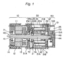
- Fig. 1 is a sectional view taken along a longitudinal axis of an air supply device according to the present invention, particularly depicting a general construction of the air supply device.
- the air supply device includes a drive section (motor section) 10, a compression mechanism section 20, and a discharge casing section 50.
- the drive section 10 includes a cylindrical motor frame 11, a stator 12 secured to an inner surface of the motor frame 11, a rotor 13 secured to a motor shaft 41 to rotate within the stator 12, and a motor bearing plate 14 for closing one end of the motor frame 11.
- the motor bearing plate 14 includes a first bearing 71 secured thereto at a central portion thereof, which in turn rotatably supports one end of the motor shaft 41.
- the compression mechanism section 20 includes an orbiting scroll 21 operated by the action of an orbiting shaft 42, a stationary scroll 22 for forming a plurality of compression chambers 26 between it and the orbiting scroll 21, and a plurality of rotation constraint members 23 operable to orbit the orbiting scroll 21.
- the orbiting scroll 21 has an orbiting scroll wrap 21A unitarily formed with an end plate and having a predetermined height
- the stationary scroll 22 has a stationary scroll wrap 22A unitarily formed with an end plate and having a predetermined height.
- the orbiting scroll wrap 21A and the stationary scroll wrap 22A are positioned so as to engage with each other.
- a clearance is provided between a side surface of the orbiting scroll wrap 21 A and that of the stationary scroll wrap 22A so that they may not be brought , into contact with each other.
- the orbiting scroll wrap 21A and the stationary scroll wrap 22A are each provided at an end surface thereof with a tip seal 21 B or 22B, respectively. Accordingly, the end surface of the orbiting scroll wrap 21A is held in contact with the stationary scroll 22 by way of the tip seal 21 B, while the end surface of the stationary scroll wrap 22A is held in contact with the orbiting scroll 21 by way of the tip seal 22B.
- the compression mechanism section 20 includes a casing 31 that is made up of a disc-shaped partition plate 31A for sealingly partitioning the other end of the motor frame 11 and one end of the compression mechanism section 20 from each other, and a cylindrical member 31 B for covering the components parts accommodated in the casing 31.
- the partition plate 31A has a through-hole 33 defined therein at a central portion thereof, in which a second bearing 72 is received to rotatably support the other end of the motor shaft 41.
- the cylindrical member 31 B has a suction port 24 defined therein, through which air is introduced into the compression mechanism section 20.
- the discharge casing section 50 includes a discharge casing 51 that in turn includes a disc-shaped plate 51A and a cylindrical member 51 B secured to or otherwise integrally formed with an outer peripheral portion of the plate 51 A.
- the plate 51A is provided with a third bearing 73 secured thereto at a central portion thereof.
- An adapter 48 is secured to the other end of the orbiting shaft 42 and rotatably supported by the third bearing 73 with the center of the adapter 48 held in alignment with a rotation center of the motor shaft. 41.
- the plate 51A has a discharge port .25 defined therein, through which air compressed by the compression mechanism section 20 is discharged.
- each rotation constraint member 23 includes a crankpin 23A interposed between the casing 31 and the orbiting scroll 21, and the crankpin 23A is provided with bearings 23B, 23C that rotatably support opposite ends of the crankpin 23A, respectively.
- a grease-filled ball bearing is preferably used as the bearings 23B, 23C.
- a plurality of (for example, three) crankpins 23A are interposed between the partition plate 31A and the orbiting scroll 21 and equally spaced from the orbiting shaft 42 and also from each other.
- a rotary shaft 40 is made up of the motor shaft 41 and the orbiting shaft 42 unitarily formed with each other and both referred to above.
- the rotary shaft 40 is rotatably supported at one end thereof by the first bearing 71, at an intermediate portion thereof by the second bearing 72, and at the other end thereof by the third bearing 73 via the adapter 48. Because the motor shaft 41 is supported by the first bearing 71 and the second bearing 72 and because the orbiting shaft 42 is supported by the second bearing 72 and the third bearing 73, both the motor shaft 41 and the orbiting shaft 42 are of a construction supported at opposite ends thereof.
- the rotary shaft 40 is crank-shaped, that is, the orbiting shaft 42 is eccentric with respect to the motor shaft 41.
- the orbiting shaft 42 is provided with two bearings 74, 75 mounted thereon, by which the orbiting scroll 21 is rotatably supported.
- the bearing 74 is located on the root side of the orbiting scroll wrap 21A, while the bearing 75 is located on the distal end side of the orbiting scroll wrap 21 A.
- the orbiting shaft 42 is also provided with a pre-loading spring 44 interposed between a balance weight 47 and the bearing 75 under the condition in which a compression load is applied thereto. Accordingly, the pre-loading spring 44 presses an inner ring of the bearing 75 towards the drive section 10, and a load applied to the inner ring is transmitted to an outer ring of the bearing 75 via balls, thereby pressing the orbiting scroll 21 towards the drive section 10.
- the load applied to the orbiting scroll 21 is received by the crankpins 23A to prevent the orbiting scroll 21 from overturning during a low-speed operation, thereby suppressing vibrations.
- the orbiting shaft 42 is provided with a shaft seal 45 juxtaposed with the bearing 75 at a location between the bearing 74 and the bearing 75.
- the shaft seal 45 is intended to prevent the compressed air from leaking to the side of the bearing 74.
- the air supply device employs grease-filled bearings as the first bearing 71, the second bearing 72, the third bearing 73, the bearings 74,75 and the bearings 23B, 23C.
- the use of such bearings confines the sliding portions to only the inside of the bearings, which is lubricated by the grease, making it possible to supply clean air.
- Fig. 2 is a sectional view taken along a longitudinal axis of the orbiting scroll 21, and as shown therein, the orbiting scroll 21 is provided with two bearings 74, 75 mounted on the orbiting shaft 42 and a plurality of bearings 23B each constituting the rotation constraint member 23.
- Fig. 3 depicts one of the bearings 74, 75, 23B referred to above, and the -internal construction of the bearing, generally identified by 80, is explained hereinafter with reference to Fig. 3.
- the bearing 80 is internally filled with grease, on which a centrifugal force acts during operation, which in turn acts to render the grease to leak outside the bearing 80.
- a centrifugal force acts during operation, which in turn acts to render the grease to leak outside the bearing 80.
- the grease scatters outside, resulting in a reduction in the life of the bearing 80.
- each sealing material 81 mounted in the bearing 80 has a generally L-shaped section taken along an axial center of the bearing 80 and also has inner and outer ends held in contact with the inner ring 82 and the outer ring 83 of the bearing 80, respectively.
- the sealing material 81 is held in contact with the inner ring 82 and the outer ring 83 of the bearing 80, the interior and the exterior of the bearing 80 are partitioned without any gap and, hence, even if a centrifugal force acts on the grease inside the bearing 80, leakage of the grease is avoided.
- a sealing material 81A intended for the external pressure may be used as a high-pressure side one of the bearing 80, while a sealing material 81 B intended for the internal pressure may be used as a low-pressure side one of the bearing 80.
- the sealing material 81A facing the high-pressure air has bent portions formed at inner and outer end portions thereof, which bent portions have been bent towards the low-pressure side so that an end of the inner bent portion may be brought into closer contact with the inner ring 82 as the atmospheric pressure increases.
- the sealing, material 81 B facing the low-pressure air has an inner bent portion that has been bent towards the low-pressure side, contrary to an outer bent portion, so that an end of the inner bent portion may be brought into closer contact with the inner ring 82 as the internal pressure of the bearing 80 increases.
- the sealing material 81 When the sealing material 81 is positively brought into contact with the inner ring 82 to enhance the sealing properties, heat is inevitably generated, which in turn reduces the life of the sealing material 81. Because the sealing material 81 becomes hard depending on the temperature, it is important to select rubber having a high heat resistance. Accordingly, acrylic rubber, Teflon rubber or fluoro rubber is preferably used for the sealing material 81. Although the heat resistance increases in the order of acrylic rubber, Teflon rubber and fluoro rubber, it is preferred that the maximum speed be set as one standard for selection.
- the crankpin 23A has two shafts formed on respective sides thereof for insertion into respective bearings, and each shaft has a groove 23L defined in a surface thereof so as to extend parallel to a longitudinal axis thereof.
- an engagement recess 21H formed in the end plate of the orbiting scroll 21 for insertion of the bearing 23B thereinto may have a groove 21L formed in an inner surface thereof so as to extend parallel to the longitudinal axis of the shaft of the crankpin 23A, as shown in Fig. 6, or an engagement recess formed in the casing 31 (partition plate 31A) may similarly have a groove formed in an inner surface thereof so as to extend parallel to the longitudinal axis of the shaft of the crankpin 23A.
- the air escape groove 21L, 23L has a width and a depth both in the range of 0.1 mm to 1.0mm. If the groove is too large (if the width or depth of the groove exceeds 1.0mm), there is a possibility that the crankpin 23A, the engaging portion 21H of the orbiting scroll 21, or the engaging portion of the casing 31 is reduced in strength and can not withstand the load during operation, though such a groove is preferable as an air escape one. In contrast, If the groove is too small (if the width or depth of the groove is less than 0.1mm), there is a possibility that the groove cannot achieve a sufficient function as an air escape one.
- the width and depth of the air escape groove 21L, 23L in the range referred to above, it is possible to ensure the strength of the crankpin 23A, the engaging portion 21H of the orbiting scroll 21, or the engaging portion of the casing 31 and the function as the air escape groove at the same time.
Landscapes
- Engineering & Computer Science (AREA)
- General Engineering & Computer Science (AREA)
- Mechanical Engineering (AREA)
- Rotary Pumps (AREA)
- Applications Or Details Of Rotary Compressors (AREA)
Applications Claiming Priority (2)
| Application Number | Priority Date | Filing Date | Title |
|---|---|---|---|
| JP2003171642 | 2003-06-17 | ||
| PCT/JP2004/008676 WO2004111458A1 (fr) | 2003-06-17 | 2004-06-15 | Dispositif d'acheminement d'air |
Publications (3)
| Publication Number | Publication Date |
|---|---|
| EP1640612A1 true EP1640612A1 (fr) | 2006-03-29 |
| EP1640612A4 EP1640612A4 (fr) | 2009-05-06 |
| EP1640612B1 EP1640612B1 (fr) | 2010-03-31 |
Family
ID=33549458
Family Applications (1)
| Application Number | Title | Priority Date | Filing Date |
|---|---|---|---|
| EP04746151A Expired - Lifetime EP1640612B1 (fr) | 2003-06-17 | 2004-06-15 | Dispositif d'acheminement d'air |
Country Status (6)
| Country | Link |
|---|---|
| US (1) | US7296982B2 (fr) |
| EP (1) | EP1640612B1 (fr) |
| JP (1) | JP4647489B2 (fr) |
| CN (1) | CN100472068C (fr) |
| DE (1) | DE602004026307D1 (fr) |
| WO (1) | WO2004111458A1 (fr) |
Cited By (1)
| Publication number | Priority date | Publication date | Assignee | Title |
|---|---|---|---|---|
| EP2594797A3 (fr) * | 2011-11-18 | 2016-04-27 | Kabushiki Kaisha Toyota Jidoshokki | Compresseur pour véhicule |
Families Citing this family (7)
| Publication number | Priority date | Publication date | Assignee | Title |
|---|---|---|---|---|
| US8336328B2 (en) * | 2005-08-22 | 2012-12-25 | Ntn Corporation | Air cycle refrigerating/cooling system and turbine unit used therefor |
| JP4812367B2 (ja) * | 2005-08-24 | 2011-11-09 | Ntn株式会社 | 空気サイクル冷凍冷却システムおよびその空気サイクル冷凍冷却用タービンユニット |
| JP5591135B2 (ja) | 2011-01-28 | 2014-09-17 | 三菱重工業株式会社 | 電動圧縮機およびその組立方法 |
| JP6156232B2 (ja) * | 2014-04-01 | 2017-07-05 | 株式会社豊田自動織機 | 電動過給機 |
| KR102043154B1 (ko) * | 2018-05-04 | 2019-11-11 | 엘지전자 주식회사 | 전동식 압축기 |
| CN114110644B (zh) * | 2021-11-25 | 2022-08-02 | 淄博金通电力科技有限公司 | 一种受热面回转式空气预热器及其密封组件与制备方法 |
| CN115773247B (zh) * | 2022-11-08 | 2024-05-31 | 上海本菱涡旋压缩机有限公司 | 一种涡旋式压缩机 |
Citations (4)
| Publication number | Priority date | Publication date | Assignee | Title |
|---|---|---|---|---|
| US2310607A (en) * | 1941-06-11 | 1943-02-09 | Norma Hoffmann Bearing Corp | Rubber bonded split metal washer seal |
| US4655617A (en) * | 1985-10-11 | 1987-04-07 | Koyo Seiko Co., Ltd. | Sealed rolling bearing with a flow reducing grease passage |
| JP2000161372A (ja) * | 1998-11-20 | 2000-06-13 | Ntn Corp | 転がり軸受 |
| JP2002070764A (ja) * | 2000-08-29 | 2002-03-08 | Toyota Industries Corp | スクロール型圧縮機 |
Family Cites Families (14)
| Publication number | Priority date | Publication date | Assignee | Title |
|---|---|---|---|---|
| JPS6259788A (ja) | 1985-09-06 | 1987-03-16 | 電気化学工業株式会社 | ドア構造体 |
| JPH02277985A (ja) * | 1989-04-20 | 1990-11-14 | Hitachi Ltd | スクロール形流体機械 |
| JPH05296168A (ja) * | 1992-04-17 | 1993-11-09 | Hitachi Ltd | スクロール圧縮機 |
| JP3341930B2 (ja) * | 1993-07-16 | 2002-11-05 | トキコ株式会社 | スクロール式流体機械 |
| JPH0754784A (ja) * | 1993-08-09 | 1995-02-28 | Hitachi Ltd | 軸貫通スクロール圧縮機 |
| JPH07332264A (ja) * | 1994-06-03 | 1995-12-22 | Hitachi Ltd | 軸貫通スクロ−ル圧縮機 |
| JPH08270662A (ja) * | 1995-02-03 | 1996-10-15 | Koyo Seiko Co Ltd | 軸受の密封装置 |
| JP3010174B2 (ja) * | 1995-11-24 | 2000-02-14 | 株式会社安永 | スクロール型流体機械 |
| JP3812113B2 (ja) * | 1997-12-25 | 2006-08-23 | 日立工機株式会社 | スクロール形真空ポンプ |
| JP2000297757A (ja) * | 1999-04-14 | 2000-10-24 | Sanden Corp | 圧縮機 |
| JP2001073969A (ja) * | 1999-08-30 | 2001-03-21 | Nippon Soken Inc | スクロール型圧縮機 |
| JP2002130305A (ja) * | 2000-10-19 | 2002-05-09 | Nsk Ltd | ラジアル玉軸受 |
| JP2002303330A (ja) * | 2001-02-05 | 2002-10-18 | Nsk Ltd | 転がり軸受 |
| JP2003227476A (ja) * | 2002-02-05 | 2003-08-15 | Matsushita Electric Ind Co Ltd | 空気供給装置 |
-
2004
- 2004-06-15 WO PCT/JP2004/008676 patent/WO2004111458A1/fr active Application Filing
- 2004-06-15 US US10/560,428 patent/US7296982B2/en not_active Expired - Fee Related
- 2004-06-15 EP EP04746151A patent/EP1640612B1/fr not_active Expired - Lifetime
- 2004-06-15 CN CNB2004800170878A patent/CN100472068C/zh not_active Expired - Fee Related
- 2004-06-15 JP JP2005507015A patent/JP4647489B2/ja not_active Expired - Fee Related
- 2004-06-15 DE DE602004026307T patent/DE602004026307D1/de not_active Expired - Lifetime
Patent Citations (4)
| Publication number | Priority date | Publication date | Assignee | Title |
|---|---|---|---|---|
| US2310607A (en) * | 1941-06-11 | 1943-02-09 | Norma Hoffmann Bearing Corp | Rubber bonded split metal washer seal |
| US4655617A (en) * | 1985-10-11 | 1987-04-07 | Koyo Seiko Co., Ltd. | Sealed rolling bearing with a flow reducing grease passage |
| JP2000161372A (ja) * | 1998-11-20 | 2000-06-13 | Ntn Corp | 転がり軸受 |
| JP2002070764A (ja) * | 2000-08-29 | 2002-03-08 | Toyota Industries Corp | スクロール型圧縮機 |
Non-Patent Citations (1)
| Title |
|---|
| See also references of WO2004111458A1 * |
Cited By (1)
| Publication number | Priority date | Publication date | Assignee | Title |
|---|---|---|---|---|
| EP2594797A3 (fr) * | 2011-11-18 | 2016-04-27 | Kabushiki Kaisha Toyota Jidoshokki | Compresseur pour véhicule |
Also Published As
| Publication number | Publication date |
|---|---|
| CN1809696A (zh) | 2006-07-26 |
| DE602004026307D1 (de) | 2010-05-12 |
| JPWO2004111458A1 (ja) | 2006-07-27 |
| US7296982B2 (en) | 2007-11-20 |
| US20060177333A1 (en) | 2006-08-10 |
| EP1640612B1 (fr) | 2010-03-31 |
| EP1640612A4 (fr) | 2009-05-06 |
| JP4647489B2 (ja) | 2011-03-09 |
| WO2004111458A1 (fr) | 2004-12-23 |
| CN100472068C (zh) | 2009-03-25 |
Similar Documents
| Publication | Publication Date | Title |
|---|---|---|
| US6439867B1 (en) | Scroll compressor having a clearance for the oldham coupling | |
| JP2008255797A (ja) | オイルフリーロータリコンプレッサのロータ軸シール装置 | |
| EP1640612B1 (fr) | Dispositif d'acheminement d'air | |
| US6179591B1 (en) | Conical hub bearing for scroll machine | |
| JP4681322B2 (ja) | スクロール圧縮機 | |
| JPH0617674B2 (ja) | スクロール流体機械 | |
| JPH08326671A (ja) | スクロール圧縮機 | |
| JP3045898B2 (ja) | スクロール圧縮機 | |
| US6135736A (en) | Scroll machine with non-machined anti-thrust surface | |
| JPH0988849A (ja) | スクロール式流体機械 | |
| JP2000291579A (ja) | 水冷式ガス供給装置 | |
| CN219754796U (zh) | 涡旋压缩机及车辆 | |
| JP2006207406A (ja) | スクロール流体機械 | |
| JP2007211639A (ja) | オイルフリースクリュー圧縮機 | |
| CN216518614U (zh) | 泵和车辆 | |
| JP2019056336A (ja) | スクロール型流体機械 | |
| JP4142383B2 (ja) | 全系回転式スクロール圧縮機 | |
| JP2009085102A (ja) | スクロール式流体機械 | |
| JPH04159480A (ja) | スクリュー圧縮機 | |
| CN115875256A (zh) | 泵和车辆 | |
| JP5285339B2 (ja) | スクロール圧縮機 | |
| JP6004667B2 (ja) | 圧縮機 | |
| CN116816673A (zh) | 压缩机 | |
| JP2940365B2 (ja) | スクロール圧縮機 | |
| JP2007205297A (ja) | スクロール圧縮機 |
Legal Events
| Date | Code | Title | Description |
|---|---|---|---|
| PUAI | Public reference made under article 153(3) epc to a published international application that has entered the european phase |
Free format text: ORIGINAL CODE: 0009012 |
|
| 17P | Request for examination filed |
Effective date: 20060117 |
|
| AK | Designated contracting states |
Kind code of ref document: A1 Designated state(s): DE FR GB |
|
| DAX | Request for extension of the european patent (deleted) | ||
| RBV | Designated contracting states (corrected) |
Designated state(s): DE FR GB |
|
| RAP1 | Party data changed (applicant data changed or rights of an application transferred) |
Owner name: PANASONIC CORPORATION |
|
| A4 | Supplementary search report drawn up and despatched |
Effective date: 20090407 |
|
| GRAP | Despatch of communication of intention to grant a patent |
Free format text: ORIGINAL CODE: EPIDOSNIGR1 |
|
| RIN1 | Information on inventor provided before grant (corrected) |
Inventor name: NAKAMOTO, TATSUYA Inventor name: SAKUDA, ATSUSHI Inventor name: SAWAI, KIYOSHI |
|
| GRAS | Grant fee paid |
Free format text: ORIGINAL CODE: EPIDOSNIGR3 |
|
| GRAA | (expected) grant |
Free format text: ORIGINAL CODE: 0009210 |
|
| AK | Designated contracting states |
Kind code of ref document: B1 Designated state(s): DE FR GB |
|
| REG | Reference to a national code |
Ref country code: GB Ref legal event code: FG4D |
|
| REF | Corresponds to: |
Ref document number: 602004026307 Country of ref document: DE Date of ref document: 20100512 Kind code of ref document: P |
|
| PLBE | No opposition filed within time limit |
Free format text: ORIGINAL CODE: 0009261 |
|
| STAA | Information on the status of an ep patent application or granted ep patent |
Free format text: STATUS: NO OPPOSITION FILED WITHIN TIME LIMIT |
|
| 26N | No opposition filed |
Effective date: 20110104 |
|
| PGFP | Annual fee paid to national office [announced via postgrant information from national office to epo] |
Ref country code: GB Payment date: 20130612 Year of fee payment: 10 |
|
| PGFP | Annual fee paid to national office [announced via postgrant information from national office to epo] |
Ref country code: FR Payment date: 20130624 Year of fee payment: 10 |
|
| GBPC | Gb: european patent ceased through non-payment of renewal fee |
Effective date: 20140615 |
|
| REG | Reference to a national code |
Ref country code: FR Ref legal event code: ST Effective date: 20150227 |
|
| PG25 | Lapsed in a contracting state [announced via postgrant information from national office to epo] |
Ref country code: GB Free format text: LAPSE BECAUSE OF NON-PAYMENT OF DUE FEES Effective date: 20140615 Ref country code: FR Free format text: LAPSE BECAUSE OF NON-PAYMENT OF DUE FEES Effective date: 20140630 |
|
| PGFP | Annual fee paid to national office [announced via postgrant information from national office to epo] |
Ref country code: DE Payment date: 20150609 Year of fee payment: 12 |
|
| REG | Reference to a national code |
Ref country code: DE Ref legal event code: R119 Ref document number: 602004026307 Country of ref document: DE |
|
| PG25 | Lapsed in a contracting state [announced via postgrant information from national office to epo] |
Ref country code: DE Free format text: LAPSE BECAUSE OF NON-PAYMENT OF DUE FEES Effective date: 20170103 |