EP1637459B1 - Faltschachtel und Verfahren und Vorrichtung zu dessen Herstellung - Google Patents
Faltschachtel und Verfahren und Vorrichtung zu dessen Herstellung Download PDFInfo
- Publication number
- EP1637459B1 EP1637459B1 EP04425703A EP04425703A EP1637459B1 EP 1637459 B1 EP1637459 B1 EP 1637459B1 EP 04425703 A EP04425703 A EP 04425703A EP 04425703 A EP04425703 A EP 04425703A EP 1637459 B1 EP1637459 B1 EP 1637459B1
- Authority
- EP
- European Patent Office
- Prior art keywords
- container
- pleating
- disposed
- walls
- plates
- Prior art date
- Legal status (The legal status is an assumption and is not a legal conclusion. Google has not performed a legal analysis and makes no representation as to the accuracy of the status listed.)
- Not-in-force
Links
Images


Classifications
-
- B—PERFORMING OPERATIONS; TRANSPORTING
- B65—CONVEYING; PACKING; STORING; HANDLING THIN OR FILAMENTARY MATERIAL
- B65D—CONTAINERS FOR STORAGE OR TRANSPORT OF ARTICLES OR MATERIALS, e.g. BAGS, BARRELS, BOTTLES, BOXES, CANS, CARTONS, CRATES, DRUMS, JARS, TANKS, HOPPERS, FORWARDING CONTAINERS; ACCESSORIES, CLOSURES, OR FITTINGS THEREFOR; PACKAGING ELEMENTS; PACKAGES
- B65D5/00—Rigid or semi-rigid containers of polygonal cross-section, e.g. boxes, cartons or trays, formed by folding or erecting one or more blanks made of paper
- B65D5/18—Rigid or semi-rigid containers of polygonal cross-section, e.g. boxes, cartons or trays, formed by folding or erecting one or more blanks made of paper by folding a single blank to U-shape to form the base of the container and opposite sides of the body portion, the remaining sides being formed primarily by extensions of one or more of these opposite sides, e.g. flaps hinged thereto
-
- B—PERFORMING OPERATIONS; TRANSPORTING
- B65—CONVEYING; PACKING; STORING; HANDLING THIN OR FILAMENTARY MATERIAL
- B65D—CONTAINERS FOR STORAGE OR TRANSPORT OF ARTICLES OR MATERIALS, e.g. BAGS, BARRELS, BOTTLES, BOXES, CANS, CARTONS, CRATES, DRUMS, JARS, TANKS, HOPPERS, FORWARDING CONTAINERS; ACCESSORIES, CLOSURES, OR FITTINGS THEREFOR; PACKAGING ELEMENTS; PACKAGES
- B65D5/00—Rigid or semi-rigid containers of polygonal cross-section, e.g. boxes, cartons or trays, formed by folding or erecting one or more blanks made of paper
- B65D5/20—Rigid or semi-rigid containers of polygonal cross-section, e.g. boxes, cartons or trays, formed by folding or erecting one or more blanks made of paper by folding-up portions connected to a central panel from all sides to form a container body, e.g. of tray-like form
- B65D5/24—Rigid or semi-rigid containers of polygonal cross-section, e.g. boxes, cartons or trays, formed by folding or erecting one or more blanks made of paper by folding-up portions connected to a central panel from all sides to form a container body, e.g. of tray-like form with adjacent sides interconnected by gusset folds
- B65D5/241—Rigid or semi-rigid containers of polygonal cross-section, e.g. boxes, cartons or trays, formed by folding or erecting one or more blanks made of paper by folding-up portions connected to a central panel from all sides to form a container body, e.g. of tray-like form with adjacent sides interconnected by gusset folds and the gussets folds connected to the inside of the container body
- B65D5/243—Rigid or semi-rigid containers of polygonal cross-section, e.g. boxes, cartons or trays, formed by folding or erecting one or more blanks made of paper by folding-up portions connected to a central panel from all sides to form a container body, e.g. of tray-like form with adjacent sides interconnected by gusset folds and the gussets folds connected to the inside of the container body the container body comprising a continuous rim or flange
-
- B—PERFORMING OPERATIONS; TRANSPORTING
- B65—CONVEYING; PACKING; STORING; HANDLING THIN OR FILAMENTARY MATERIAL
- B65D—CONTAINERS FOR STORAGE OR TRANSPORT OF ARTICLES OR MATERIALS, e.g. BAGS, BARRELS, BOTTLES, BOXES, CANS, CARTONS, CRATES, DRUMS, JARS, TANKS, HOPPERS, FORWARDING CONTAINERS; ACCESSORIES, CLOSURES, OR FITTINGS THEREFOR; PACKAGING ELEMENTS; PACKAGES
- B65D5/00—Rigid or semi-rigid containers of polygonal cross-section, e.g. boxes, cartons or trays, formed by folding or erecting one or more blanks made of paper
- B65D5/20—Rigid or semi-rigid containers of polygonal cross-section, e.g. boxes, cartons or trays, formed by folding or erecting one or more blanks made of paper by folding-up portions connected to a central panel from all sides to form a container body, e.g. of tray-like form
- B65D5/22—Rigid or semi-rigid containers of polygonal cross-section, e.g. boxes, cartons or trays, formed by folding or erecting one or more blanks made of paper by folding-up portions connected to a central panel from all sides to form a container body, e.g. of tray-like form held erect by extensions of one or more sides being doubled-over to enclose extensions of adjacent sides
-
- B—PERFORMING OPERATIONS; TRANSPORTING
- B65—CONVEYING; PACKING; STORING; HANDLING THIN OR FILAMENTARY MATERIAL
- B65D—CONTAINERS FOR STORAGE OR TRANSPORT OF ARTICLES OR MATERIALS, e.g. BAGS, BARRELS, BOTTLES, BOXES, CANS, CARTONS, CRATES, DRUMS, JARS, TANKS, HOPPERS, FORWARDING CONTAINERS; ACCESSORIES, CLOSURES, OR FITTINGS THEREFOR; PACKAGING ELEMENTS; PACKAGES
- B65D5/00—Rigid or semi-rigid containers of polygonal cross-section, e.g. boxes, cartons or trays, formed by folding or erecting one or more blanks made of paper
- B65D5/42—Details of containers or of foldable or erectable container blanks
- B65D5/44—Integral, inserted or attached portions forming internal or external fittings
-
- B—PERFORMING OPERATIONS; TRANSPORTING
- B31—MAKING ARTICLES OF PAPER, CARDBOARD OR MATERIAL WORKED IN A MANNER ANALOGOUS TO PAPER; WORKING PAPER, CARDBOARD OR MATERIAL WORKED IN A MANNER ANALOGOUS TO PAPER
- B31B—MAKING CONTAINERS OF PAPER, CARDBOARD OR MATERIAL WORKED IN A MANNER ANALOGOUS TO PAPER
- B31B50/00—Making rigid or semi-rigid containers, e.g. boxes or cartons
- B31B50/59—Shaping sheet material under pressure
- B31B50/592—Shaping sheet material under pressure using punches or dies
-
- Y—GENERAL TAGGING OF NEW TECHNOLOGICAL DEVELOPMENTS; GENERAL TAGGING OF CROSS-SECTIONAL TECHNOLOGIES SPANNING OVER SEVERAL SECTIONS OF THE IPC; TECHNICAL SUBJECTS COVERED BY FORMER USPC CROSS-REFERENCE ART COLLECTIONS [XRACs] AND DIGESTS
- Y10—TECHNICAL SUBJECTS COVERED BY FORMER USPC
- Y10T—TECHNICAL SUBJECTS COVERED BY FORMER US CLASSIFICATION
- Y10T156/00—Adhesive bonding and miscellaneous chemical manufacture
- Y10T156/10—Methods of surface bonding and/or assembly therefor
- Y10T156/1002—Methods of surface bonding and/or assembly therefor with permanent bending or reshaping or surface deformation of self sustaining lamina
- Y10T156/1043—Subsequent to assembly
- Y10T156/1044—Subsequent to assembly of parallel stacked sheets only
- Y10T156/1048—Subsequent to assembly of parallel stacked sheets only to form dished or receptacle-like product
-
- Y—GENERAL TAGGING OF NEW TECHNOLOGICAL DEVELOPMENTS; GENERAL TAGGING OF CROSS-SECTIONAL TECHNOLOGIES SPANNING OVER SEVERAL SECTIONS OF THE IPC; TECHNICAL SUBJECTS COVERED BY FORMER USPC CROSS-REFERENCE ART COLLECTIONS [XRACs] AND DIGESTS
- Y10—TECHNICAL SUBJECTS COVERED BY FORMER USPC
- Y10T—TECHNICAL SUBJECTS COVERED BY FORMER US CLASSIFICATION
- Y10T428/00—Stock material or miscellaneous articles
- Y10T428/13—Hollow or container type article [e.g., tube, vase, etc.]
Definitions
- the present invention refers to a container with at least three dimensions (sides) constituting a tray of flexible material, and to a relative manufacturing method and apparatus for production of said tray.
- the invention proposes a container as an alternative to the plastic containers currently existing on the market, injection moulded or thermoformed from a flat, high-thickness sheet of plastic or aluminium and drawn.
- Such containers are made with different processes and are normally provided with a hingedly openable lid, beneath which may be disposed a sheet which tightly closes the container, or they are provided with a lid welded onto their upper part.
- the thickness of the barrier must be suitably high in order to ensure a low permeability to gas or to steam even at the points of greatest deformation and thinning of the wall.
- the barriered plastic trays thus produced - that is by means of thermoforming - cannot be used for packaging moist foods (whose preservation often requires thermal sterilizing treatments) as the stretching process they have undergone tends to make the container collapse under the action of heat.
- US 3,550,835 discloses a tapered container comprising a bottom wall, obliquely inclined side walls and triangular connecting walls.
- US 4,018,378 discloses a container according to the preamble of claim 1 comprising a bottom wall, vertical side walls and trapezoidal connecting walls obliquely inclined inward with respect the bottom wall.
- US 4,057,380 discloses an apparatus to produce a tapered container without connecting walls between side walls.
- the object of the invention is to provide a container that offers a valid alternative to the above containers, maintaining the advantages thereof and eliminating the drawbacks.
- an object of the invention is to provide such a container that can be made in a simple, economical manner and at high speed.
- Another object of the invention is to provide such a container that maintains a rigid consistency during use but that can be crumpled and considerably reduced in volume when being discarded, thus facilitating waste disposal.
- Yet another object of the present invention is to provide a system for production of such a container that is economical and allows a high production speed.
- the container according to the invention is made of a flexible material, particularly single- or multi-layer plastic, possibly coupled with a layer of aluminium, which is very thin because it has only to provide a barrier effect without any supporting function.
- the container is obtained from a blank - advantageously square, rectangular or polygonal in shape - whose areas near the corners are pleated, that is suitably folded inward and outward, so as to give the container, which takes on the shape of a three-dimensional tray, a certain capacity and consistency in the vertical direction.
- Stiffening, if any, in the transverse direction can be obtained, on the other hand, by means of a small frame applied by heat-sealing, by gluing or by other means beneath the upper peripheral edge of the container or by folding of the edge.
- the container is then advantageously closed by a sheet, peelable or not, preferably provided with a pull-tab.
- Another characteristic that distinguishes the container thus formed if compared with the above-mentioned drawn types is the easy dressing and illustration on all sides.
- the flexible material that forms the container can easily be printed with high-speed processes, reel to reel, since it is in any case of limited thickness (maximum 350 microns). Furthermore, construction of the container does not deform the printing, as happens with drawing processes.
- Another property of the laminate forming the container is the possibility of having a susceptor function, that is of transforming microwave radiation into thermal energy by printing with inks having said property or by lamination of metallised films with a susceptor effect, all thanks to the homogeneous, planar structure thereof.
- the susceptor activity of the laminate can be controlled by the amount of susceptor printing applied, so as to generate areas of the container with different heating, obtaining different cooking when placed in the microwave oven.
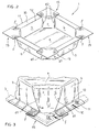
- the container 1 is realised, in the way that will be described hereunder, starting from a blank 2, shown in Figure 1 , which is suitably folded and possibly stiffened with a frame 3, shown hatched in Figure 2 .
- Said frame can be made in several ways. For example, it can be made by means of a continuously extruded wire strip developed from a reel which, when cut into segments, forms the frame without requiring the use of costly moulds.
- the material can have electrical conductivity characteristics so that welding can take place very swiftly by means of induction or ultrasound heating.
- the container 1 is normally closed by a covering sheet 4, peelable or not, not shown in the figures. Before such closing, as shown in Figures 2 and 3 , the formed container has corner portions 15 protruding outward with respect to the upper edge. After application of the covering sheet, the upper edge of the container is trimmed or die-cut, so as to obtain a substantially rectangular perimeter.
- the container 1 is made is now described, starting from the blank 2, which is a single- or multi-layer sheet of a material with one or more layers, in particular layers of plastic material - such as polyethylene, polyester, polypropylene, polyamide EVOH - and/or metals, such as aluminium.
- plastic material - such as polyethylene, polyester, polypropylene, polyamide EVOH - and/or metals, such as aluminium.
- the square-shaped blank 2 which does not have breaks in continuity, gives rise to an octagonal tray, but clearly it could also be rectangular or generally polygonal in shape, in which case a tray of substantially the same polygonal shape would be formed, but with the addition of connecting sides at the corners.
- the octagon denoted by a will form the bottom of the container 1
- the four trapeziums indicated by b will form the side walls
- the squares c at the four apexes will form the four connecting walls between the four side walls b.
- the connecting walls c are obtained by pleating of the eight triangular portions d disposed between the connecting walls c and the side walls b. Pleating takes place by bringing the fold lines d1 between the side wall b and the triangle of pleating d toward the outside of the container and bringing the fold lines d2 between the connecting wall c and the triangle of pleating d toward the inside of the container.
- a peripheral edge 10 of the blank 2 defined by the square outer edge 11 of the blank and by an inner octagonal peripheral line 12, dashed in Figure 1 , is folded over during formation of the container 1.
- each area of heat-sealing f is defined by a first segment f1 which prolongs the fold line d1 between the side wall b and the triangle of pleating d and a second segment f2 which starts from an apex of the triangle of pleating d and is parallel to the first segment f1.
- each triangular portion d of the blank 2 are pleated. That is, each triangular portion d is folded inward with respect to the side wall b along the fold line d1 which is brought outward. Furthermore, each triangular portion d is folded outward with respect to the connecting wall c along the fold line d2, which is brought inward.
- the four side walls b are raised with respect to the bottom a, forming the four substantially vertical connecting walls c so as to increase the stiffness and the resistance to compression of the container 1.
- the square connecting wall c stiffens the corresponding corner of the container 1, especially in the vertical direction, acting as a strut.
- Figure 3 shows an enlargement of the apex of the container 1, where cuts in the laminate are not present in order to ensure the perfect tightness of the package.
- the frame 3 which is made of a sufficiently rigid plastic material, is inserted, if necessary, from beneath and the peripheral edge 10 of the blank, is folded thereon and is fixed thereto with suitable means, such as heat-sealing, adhesive and the like.
- the frame 3 gives the container 1 a stiffness prevalently in the transverse directions which, together with the vertical stiffness imparted by the square connecting walls c acting as corner struts, determines a structure which is substantially rigid during use, despite being made in large part of flexible material.
- the tray container 1 may then be closed with a suitable lid, for example by applying to the upper edge 10 thereof - by heat sealing, gluing or the like - a single- or multi-layer sheet 4.
- the protruding corner parts 15 are then trimmed so as to obtain a substantially rectangular and uniform upper peripheral edge
- the covering sheet can be removed by peeling or otherwise, an operation which is facilitated by providing a pull-tab thereon.
- the advantages of the container according to the invention are evident, in that it is made in an extremely simple and economical manner being made up essentially of a blank 2 of flexible sheet material, of a substantially rigid frame 3 (if any) and of a covering sheet, if any.
- the production process of the container 1 can easily be automated, providing for automatic pleating of the eight triangular portions d near the apexes of the blank 2, to form a parallelepiped tray, insertion of the frame, if any, and folding and fixing on the frame of the peripheral edge 10.
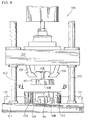
- an apparatus 100 is described for realising a tray-shaped container according to the invention.
- the apparatus 100 consists of a vertical press and comprises a base frame 101 on which are mounted vertical guide columns 102.
- a mobile plate or crosspiece 103 operated in vertical translation by means that are not shown, is mounted vertically slidably on the guide columns 102.
- a support 106 is mounted in the mobile plate 103 and protrudes downward therefrom.
- a top mould 108 is fixed to the support 106 by means of a vertical shaft 107, provided with a certain vertical play.
- the top mould 108 is shaped substantially as an octagonal plate which reproduces the outline of the bottom a ( Figure 1 ) of the container to be realised.
- a bottom mould 128 is mounted, with a certain vertical play, on the base frame 101.
- the bottom mould 128 is mounted on compression spring means (not shown) ad has a vertical stroke selected to be equal to the depth of the container 2 that is to be formed.
- the bottom mould 128 has the same octagonal plate shape as the top mould 108 and is disposed in register therewith.
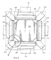
- Four heating side plates 129 are provided at the larger sides of the bottom mould 128.
- Each heating side plate 128 has a rectangular shape in a plan view, of a length equal to the distance between the two larger sides of the bottom mould 128.
- the front part of each heating side plate 129 is disposed near the larger side of the bottom mould 128 and the rear part is supported by a support 131 disposed on the base 101 of the machine.
- each connecting and pleating plate 132 is disposed to coincide with the smaller sides or connecting sides of the bottom mould 128. As shown better in Figure 5A , each connecting and pleating plate 132 has in a plan view a triangular end portion 133 defined by two opposite L-shaped cuts 134, with an angle of 90°, within which the edges 129a of the two side heating plates 129 are received.
- the triangular portion 133 of the connecting and pleating plate is shaped as an isosceles triangle with the hypotenuse opposite the smaller side of the bottom mould 128.
- Two edges 133a with angles of 45° are subtended on the hypotenuse of the triangular part 133.
- the hypotenuse of the triangular part 133 is parallel to the smaller side of the bottom mould 128 and the catheti of the triangular part 133 are aligned with the larger sides of the bottom mould 128.
- first space 141 is formed between the larger side of the bottom mould 128 and the respective side heating plate 129
- second space 142 is formed between the smaller side of the bottom mould 128 and the hypotenuse of the triangular portion 133
- third space 143 is formed between the cathetus of the triangular portion 133 and the respective side heating plate 129.
- the top surface of the bottom mould is at the same level as the top surface of the side heating plates 129 and of the connecting and pleating plates 132.
- the flat blank 2 is disposed on the bottom mould 128 so that its peripheral part is disposed on the side heating plates 129 and on the connecting and pleating plates 132.
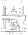
- the mobile plate 103 is lowered so that the top mould 108 abuts on the bottom mould 128 causing it to be lowered to an end of stroke point, compressing the spring means.
- the stroke of the bottom mould 128 corresponds to the depth of the tray 2.
- the fold line d2 of the triangle d is brought towards the inside of the container by means of the 45° edges 133a between the hypotenuse and the catheti of the triangular plate 133, whereas the fold line d1 is brought towards the outside by means of overlaying of the flaps inside the space 143 between the cathetus of the triangular pleating plate 133 and the heating plate 129.
- the ends of the oblique folding and heat sealing plates 109 as they descend, fold the corner parts of the edge 10 of the blank 2 in abutment against the top surface of the connecting plates 133 and the end parts of the heating plates 129.
- the oblique plates 109 act as heat-sealing counter-bars, pressing the portions of heat-sealing f on the heating plates 129.
- the heat-sealing part f ( Figure 1 ) is folded along the fold lines defined by the segments f1 and f2 and, as shown in Figure 8 , the heat-sealing part f is superimposed on the edge part 10 of the blank near the ends of the heating plates 129 in which, thanks to the pressure of the oblique plates 109, heat-sealing takes place.
- the mobile plate 103 is raised together with the top mould 108, and then the spring means are released, raising the bottom mould 128 on which the formed container is disposed.
- the container according to the invention is a valid alternative to thermoformed containers erected vertically, by means of suitable folds, from rigid or drawn materials and can be used - preferably but not exclusively - for food products.
Landscapes
- Engineering & Computer Science (AREA)
- Mechanical Engineering (AREA)
- Making Paper Articles (AREA)
- Auxiliary Devices For And Details Of Packaging Control (AREA)
- Containers Having Bodies Formed In One Piece (AREA)
- Cartons (AREA)
- Packages (AREA)
Claims (15)
- Schachtel aus flexiblem Material, die aus einem mehreckig geformten Zuschnitt (2) aus ein- oder mehrlagigem Bahnmaterial durch Fälteln und Falzen einer Außenumfangskante (10) erhalten ist, umfassend:- eine achteckige Bodenwand (a),- mehrere Seitenwände (b), die rechtwinklig von der Bodenwand (a) aufgerichtet sind,- mehrere Verbindungswände (c), die zwischen den Seitenwänden (b) angeordnet sind und durch Fälteln von dreieckigen Fältelungsabschnitten (d) in der Nähe der Ecken der Schachtel erhalten sind und zwischen den Seitenwänden (b) und den Verbindungswänden (c) angeordnet sind, und- eine obere Umfangskante (10), die nach außen gefaltet ist,dadurch gekennzeichnet, dass die Verbindungswände (c) quadratisch oder rechteckig sind und rechtwinklig zu der Bodenwand (a) angeordnet sind.
- Schachtel nach Anspruch 1, dadurch gekennzeichnet, dass die Fältelungsabschnitte (d) folgendes umfassen:- eine erste Falzlinie (d1), die der Seitenwand (b) benachbart ist und zur Außenseite der Schachtel gezogen ist, um eine Falzung des dreieckigen Abschnitts (d) nach innen bezüglich der jeweiligen Seitenwand (b) hervorzurufen, und- eine zweite Falzlinie (d2), die der Verbindungswand (c) benachbart ist und zur Innenseite der Schachtel hin gezogen ist, um eine Falzung des dreieckigen Abschnitts (d) nach außen bezüglich der jeweiligen Verbindungswand (c) hervorzurufen.
- Schachtel nach einem der vorhergehenden Ansprüche, dadurch gekennzeichnet, dass sie mehrere heißgesiegelte Teile (f) umfasst, die an der oberen Umfangskante (10) zum Übereinstimmen mit den zwischenliegenden Teilen von Fältelung (d) angeordnet sind.
- Schachtel nach einem der vorhergehenden Ansprüche, dadurch gekennzeichnet, dass sie eine achteckige Bodenwand (a), vier Seitenwände (b), vier Verbindungswände (c) und acht Fältelungsteile (d) umfasst.
- Schachtel nach einem der vorhergehenden Ansprüche, dadurch gekennzeichnet, dass die obere Umfangskante (10) nach außen gefalzt und an einem untergelagerten starren Rahmen befestigt ist, der dieselbe Mehreckform wie der Boden (a) der Schachtel aufweist.
- Schachtel nach einem der vorhergehenden Ansprüche, dadurch gekennzeichnet, dass sie eine abnehmbare Abdeckplatte vorsieht, die mithilfe von Heißsiegeln, Klebstoffen oder ähnlichen Mitteln an der Oberkante (10) der Schachtel befestigt ist.
- Verfahren zum Fertigen einer Schachtel (1) aus einem flexiblen Material ausgehend von einem mehreckig geformten Zuschnitt (2) aus ein- oder mehrlagigem Bahnmaterial nach einem der vorhergehenden Ansprüche, folgende Schritte umfassend:- Fälteln von Fältelungsabschnitten (d) in der Nähe der Scheitelpunkte des Zuschnitts (2) zum Aufrichten - bezüglich einer Bodenwand (a) - von Seitenwänden (b) und quadratischen oder rechteckigen Verbindungswänden (c), sodass die Seitenwände (b) und Verbindungswände (c) rechtwinklig zu der Bodenwand (a) angeordnet sind und die Verbindungswände (c) als Verstärkung zwischen zwei benachbarten Seitenwänden (b) wirken,- Falzen einer Umfangskante (10) des Zuschnitts (2) nach außen.
- Verfahren nach Anspruch 7, dadurch gekennzeichnet, dass die Fältelungsabschnitte (d) im Wesentlichen dreieckförmig sind und das Fälteln folgendermaßen abläuft:- Falzen des Fältelungsabschnitts (d) nach innen bezüglich der benachbarten Seitenwand (b) entlang einer ersten Falzlinie (d1) und- Falzen des Fältelungsabschnitts (d) nach außen bezüglich der benachbarten Verbindungswand (c) entlang einer zweiten Falzlinie (d2).
- Verfahren nach einem der Ansprüche 7 oder 8, dadurch gekennzeichnet, dass es einen Schritt des Heißsiegelns der Umfangskante (10) die Heißsiegelbereiche (f) entlang vorsieht, die mit den Fältelungsabschnitten (d) übereinstimmen.
- Verfahren nach einem der Ansprüche 7 bis 9, dadurch gekennzeichnet, dass die Umfangskante (10) des Zuschnitts (2) gefalzt und an einem (untergelagerten) Rahmen (3) befestigt wird.
- Verfahren nach einem der Ansprüche 7 bis 10, dadurch gekennzeichnet, dass es außerdem die Aufbringung einer ablösbaren Abdeckplatte an der oberen Umgangskante (10) der Schachtel vorsieht.
- Vorrichtung (100) zum Fertigen einer Schachtel (2) nach einem der Ansprüche 1 bis 6, dadurch gekennzeichnet, dass sie Folgendes umfasst:- eine vertikal verschiebbare Platte (103), die mit einer oberen Form (108) verbunden ist, welche als mehreckige Platte mit einer Umgangskontur geformt ist, die dem Boden (a) der Schachtel entspricht,- eine untere Form (128), die dieselbe Form wie die obere Form (108) aufweist, konturendeckend damit angeordnet ist und mit einem Hub vertikal verschiebbar ist, der gleich der Tiefe der Schachtel ist,- mehrere Seitenplatten (129), die derart in der Nähe der Seiten der unteren Form (128) angeordnet sind, dass zwischen den Seiten der unteren Form (128) und den Seitenplatten (129) jeweilige erste Räume (141) ausgebildet sind, in denen die Seitenwände (b) der Schachtel derart ausgebildet sind, dass die Seitenwände (b) rechtwinklig zu der Bodenwand (a) angeordnet sind,- mehrere Verbindungs- und Fältelungsplatten (132, 133), die derart zwischen den Seitenplatten (129) und in der Nähe der Verbindungsseiten der unteren Form (128) angeordnet sind, dass:- zwischen den Verbindungsseiten der unteren Form und den Verbindungsplatten (133) jeweilige zweite Räume (142) ausgebildet sind, in denen die Verbindungswände (c) der Schachtel derart ausgebildet sind, dass die Verbindungswände (c) quadratisch oder rechteckig sind und rechtwinklig zu der Bodenwand (a) angeordnet sind, und- zwischen den Fältelungsplatten (133) und den Seitenplatten (129) jeweilige dritte Räume (143) ausgebildet sind, in denen das Fälteln der Fältelungsabschnitte (d) der Schachtel abläuft.
- Vorrichtung nach Anspruch 12, dadurch gekennzeichnet, dass die Verbindungs- und Fältelungsplatten (132) eine dreieckige Endwand (133) umfassen, die durch zwei gegenüberliegende, L-förmige Einschnitte (134) definiert sind, in denen die Kanten (129a) der Seitenplatten (129) angeordnet sind, sodass:- der zweite Raum (142) zur Ausbildung der Verbindungswände zwischen der Hypotenuse des dreieckigen Teils (133) und der Verbindungsseite der unteren Form ausgebildet ist und- der dritte Raum (143) zum Fälteln der Fältelungsabschnitte zwischen den Katheten des dreieckigen Teils (133) und den Seitenplatten ausgebildet ist.
- Vorrichtung nach einem der Ansprüche 12 oder 13, dadurch gekennzeichnet, dass die Seitenplatten (129) einen elektrischen Heizwiderstand (130) zum Siegeln der Siegelabschnitte (f) umfassen, die an der Kante (10) der Schachtel zum Übereinstimmen mit den Abschnitten von Fältelung (d) angeordnet sind.
- Vorrichtung nach Anspruch 12, dadurch gekennzeichnet, dass sie ferner Falz- und Heißsiegelplatten (109) umfasst, die auf der verschiebbaren Platte (103) angeordnet sind und fähig sind, übereinstimmend mit den Verbindungsplatten (132) zum Falzen der Ecken der Kante (10) der Schachtel zu wirken, und als Heißsiegelgegenschienen bezüglich der Teile in der Nähe der Kanten der Heizseitenplatten (129) wirken.
Priority Applications (10)
| Application Number | Priority Date | Filing Date | Title |
|---|---|---|---|
| DE602004017992T DE602004017992D1 (de) | 2004-09-20 | 2004-09-20 | Faltschachtel und Verfahren und Vorrichtung zu dessen Herstellung |
| ES04425703T ES2318262T3 (es) | 2004-09-20 | 2004-09-20 | Recipiente de material flexible en forma de bandeja y metodo y aparato de fabricacion relativos. |
| PL04425703T PL1637459T3 (pl) | 2004-09-20 | 2004-09-20 | Składany pojemnik, związany z nim sposób i urządzenie do jego wytwarzania |
| EP04425703A EP1637459B1 (de) | 2004-09-20 | 2004-09-20 | Faltschachtel und Verfahren und Vorrichtung zu dessen Herstellung |
| AT04425703T ATE415350T1 (de) | 2004-09-20 | 2004-09-20 | Faltschachtel und verfahren und vorrichtung zu dessen herstellung |
| PT04425703T PT1637459E (pt) | 2004-09-20 | 2004-09-20 | Embalagem dobrada e respectivos aparelho e processo de fabrico |
| US11/224,845 US20060065662A1 (en) | 2004-09-20 | 2005-09-13 | Tray-shaped container of flexible material and relative manufacturing method and apparatus |
| KR1020050086795A KR20060051382A (ko) | 2004-09-20 | 2005-09-16 | 가요성 재료의 트레이 형상 용기 및 관련 제조 방법 및장치 |
| JP2005272284A JP2006089137A (ja) | 2004-09-20 | 2005-09-20 | 柔軟な材料製の容器とその製造方法及び製造装置 |
| CN200510109931A CN100593497C (zh) | 2004-09-20 | 2005-09-20 | 柔性材料的盘形容器以及相关的制造方法和装置 |
Applications Claiming Priority (1)
| Application Number | Priority Date | Filing Date | Title |
|---|---|---|---|
| EP04425703A EP1637459B1 (de) | 2004-09-20 | 2004-09-20 | Faltschachtel und Verfahren und Vorrichtung zu dessen Herstellung |
Publications (2)
| Publication Number | Publication Date |
|---|---|
| EP1637459A1 EP1637459A1 (de) | 2006-03-22 |
| EP1637459B1 true EP1637459B1 (de) | 2008-11-26 |
Family
ID=34932771
Family Applications (1)
| Application Number | Title | Priority Date | Filing Date |
|---|---|---|---|
| EP04425703A Not-in-force EP1637459B1 (de) | 2004-09-20 | 2004-09-20 | Faltschachtel und Verfahren und Vorrichtung zu dessen Herstellung |
Country Status (10)
| Country | Link |
|---|---|
| US (1) | US20060065662A1 (de) |
| EP (1) | EP1637459B1 (de) |
| JP (1) | JP2006089137A (de) |
| KR (1) | KR20060051382A (de) |
| CN (1) | CN100593497C (de) |
| AT (1) | ATE415350T1 (de) |
| DE (1) | DE602004017992D1 (de) |
| ES (1) | ES2318262T3 (de) |
| PL (1) | PL1637459T3 (de) |
| PT (1) | PT1637459E (de) |
Families Citing this family (7)
| Publication number | Priority date | Publication date | Assignee | Title |
|---|---|---|---|---|
| US8302528B2 (en) * | 2005-10-20 | 2012-11-06 | Conagra Foods Rdm, Inc. | Cooking method and apparatus |
| JP5955512B2 (ja) * | 2011-05-31 | 2016-07-20 | 保信 藤原 | 容器 |
| CN102406227A (zh) * | 2011-09-27 | 2012-04-11 | 杨斌 | 一种用面皮盛装食料的快餐食品的加工方法 |
| DE102013006309B4 (de) * | 2013-04-12 | 2015-10-22 | Roba Services Gmbh | Verpackungssystem umfassend eine Kartonstruktur |
| WO2017003925A1 (en) * | 2015-06-30 | 2017-01-05 | Nicolas Us, Inc. | System, method, and apparatus for waveform transformation |
| BR112018068305A2 (pt) * | 2016-03-10 | 2019-01-15 | Composite Solutions Srl | método para formar um corpo do tipo envoltório e corpo do tipo envoltório obtido com tal método |
| US20180092477A1 (en) * | 2016-12-14 | 2018-04-05 | Thomas R. Duncan | Steady, non-flip plates |
Family Cites Families (13)
| Publication number | Priority date | Publication date | Assignee | Title |
|---|---|---|---|---|
| SE329804B (de) * | 1967-05-17 | 1970-10-19 | Sprinter Pack Ab | |
| SE337553B (de) * | 1970-07-06 | 1971-08-09 | Mo Och Domsjoe Ab | |
| US4057380A (en) * | 1974-04-16 | 1977-11-08 | Machida Shigyo Co., Ltd. | Tray-like container and a method of and an apparatus for manufacturing the container |
| JPS50137273A (de) * | 1974-04-16 | 1975-10-31 | ||
| SE400250B (sv) * | 1974-11-08 | 1978-03-20 | Akerlund & Rausing Ab | Tragliknande forpackning, foretredesvis avsedd for matfett e d |
| SE395865B (sv) * | 1975-04-03 | 1977-08-29 | Sprinter Pack Ab | Kartongtrag med lock |
| US4130236A (en) * | 1977-11-28 | 1978-12-19 | Federal Paper Board Co., Inc. | Tray type container |
| JPS6090131A (ja) * | 1983-10-18 | 1985-05-21 | マルハ株式会社 | 缶様容器 |
| JPH0228172Y2 (de) * | 1985-02-18 | 1990-07-30 | ||
| DE3612998A1 (de) * | 1986-04-17 | 1987-10-29 | Hoerauf Michael Maschf | Faltschale |
| JP3018048U (ja) * | 1995-05-12 | 1995-11-14 | 株式会社クラウン・パッケージ | 紙製容器 |
| JP3664607B2 (ja) * | 1999-05-24 | 2005-06-29 | ユニ・チャーム株式会社 | 包装体の製造方法および製造装置 |
| JP3084805U (ja) * | 2001-09-20 | 2002-03-29 | 共同印刷株式会社 | フランジ付紙容器 |
-
2004
- 2004-09-20 PT PT04425703T patent/PT1637459E/pt unknown
- 2004-09-20 EP EP04425703A patent/EP1637459B1/de not_active Not-in-force
- 2004-09-20 ES ES04425703T patent/ES2318262T3/es active Active
- 2004-09-20 PL PL04425703T patent/PL1637459T3/pl unknown
- 2004-09-20 AT AT04425703T patent/ATE415350T1/de active
- 2004-09-20 DE DE602004017992T patent/DE602004017992D1/de active Active
-
2005
- 2005-09-13 US US11/224,845 patent/US20060065662A1/en not_active Abandoned
- 2005-09-16 KR KR1020050086795A patent/KR20060051382A/ko not_active Application Discontinuation
- 2005-09-20 CN CN200510109931A patent/CN100593497C/zh not_active Expired - Fee Related
- 2005-09-20 JP JP2005272284A patent/JP2006089137A/ja active Pending
Also Published As
| Publication number | Publication date |
|---|---|
| ATE415350T1 (de) | 2008-12-15 |
| KR20060051382A (ko) | 2006-05-19 |
| JP2006089137A (ja) | 2006-04-06 |
| CN1751971A (zh) | 2006-03-29 |
| ES2318262T3 (es) | 2009-05-01 |
| CN100593497C (zh) | 2010-03-10 |
| DE602004017992D1 (de) | 2009-01-08 |
| PL1637459T3 (pl) | 2009-05-29 |
| US20060065662A1 (en) | 2006-03-30 |
| EP1637459A1 (de) | 2006-03-22 |
| PT1637459E (pt) | 2009-03-05 |
Similar Documents
| Publication | Publication Date | Title |
|---|---|---|
| JP7283777B2 (ja) | フラットシートで構成される複合体、複合体を得る方法、パッケージを製造する方法、および品物を包装する方法 | |
| US20060065662A1 (en) | Tray-shaped container of flexible material and relative manufacturing method and apparatus | |
| RU2631038C2 (ru) | Бумажный поддон глубокой вытяжки, способ и устройство (варианты ) для изготовления такого поддона и продуктовая упаковка с таким поддоном | |
| JP5072849B2 (ja) | ボード・トレイの製造方法、そのトレイ用のブランク、及びその方法によって得られたトレイ | |
| US8083887B2 (en) | Method of forming a container having an internal reservoir | |
| US5285954A (en) | Flexible material container | |
| WO2009106846A1 (en) | A container and blank | |
| JP2008501588A (ja) | ラミネート材料から作られる容器、ブランク及び方法 | |
| US3387427A (en) | Method of forming a carton enclosed package from a preformed foldable blank | |
| US3885730A (en) | Sterilizable package | |
| DE10111232A1 (de) | Gasdichte Lebensmittelverpackung sowie Verfahren zu deren Herstellung | |
| EP3466654B1 (de) | Verfahren zur herstellung eines versiegelten behälters | |
| KR102462013B1 (ko) | 재활용 가능한 빙과류 포장지 | |
| WO2008037986A1 (en) | A container | |
| JP3648951B2 (ja) | 紙製トレー状容器の組立方法及び紙製トレー状容器の製造装置 | |
| US20220281632A1 (en) | A container for foodstuffs and a method for manufacturing said container | |
| EP4255725A2 (de) | Verfahren zur herstellung einer lebensmittelschale und so hergestellte schale | |
| WO2008060688A1 (en) | Method of forming a container having an internal reservoir | |
| GB2544743A (en) | Stackable box | |
| JP2001002056A (ja) | 紙製容器 | |
| CN210942672U (zh) | 一种应用于盛放食材的纸盒 | |
| WO2023112360A1 (ja) | 組立式紙容器、組立式紙容器の製造方法、及び組立式紙容器の製造装置 | |
| JPH03275439A (ja) | 容器及び容器形成方法 | |
| KR20120016599A (ko) | 접이식 컵라면 용기 | |
| CN118055885A (zh) | 组装式纸容器、组装式纸容器的制造方法以及组装式纸容器的制造装置 |
Legal Events
| Date | Code | Title | Description |
|---|---|---|---|
| PUAI | Public reference made under article 153(3) epc to a published international application that has entered the european phase |
Free format text: ORIGINAL CODE: 0009012 |
|
| AK | Designated contracting states |
Kind code of ref document: A1 Designated state(s): AT BE BG CH CY CZ DE DK EE ES FI FR GB GR HU IE IT LI LU MC NL PL PT RO SE SI SK TR |
|
| AX | Request for extension of the european patent |
Extension state: AL HR LT LV MK |
|
| 17P | Request for examination filed |
Effective date: 20060918 |
|
| AKX | Designation fees paid |
Designated state(s): AT BE BG CH CY CZ DE DK EE ES FI FR GB GR HU IE IT LI LU MC NL PL PT RO SE SI SK TR |
|
| GRAP | Despatch of communication of intention to grant a patent |
Free format text: ORIGINAL CODE: EPIDOSNIGR1 |
|
| GRAS | Grant fee paid |
Free format text: ORIGINAL CODE: EPIDOSNIGR3 |
|
| GRAA | (expected) grant |
Free format text: ORIGINAL CODE: 0009210 |
|
| AK | Designated contracting states |
Kind code of ref document: B1 Designated state(s): AT BE BG CH CY CZ DE DK EE ES FI FR GB GR HU IE IT LI LU MC NL PL PT RO SE SI SK TR |
|
| REG | Reference to a national code |
Ref country code: GB Ref legal event code: FG4D |
|
| REG | Reference to a national code |
Ref country code: CH Ref legal event code: EP |
|
| REG | Reference to a national code |
Ref country code: IE Ref legal event code: FG4D |
|
| REF | Corresponds to: |
Ref document number: 602004017992 Country of ref document: DE Date of ref document: 20090108 Kind code of ref document: P |
|
| REG | Reference to a national code |
Ref country code: RO Ref legal event code: EPE |
|
| REG | Reference to a national code |
Ref country code: PT Ref legal event code: SC4A Free format text: AVAILABILITY OF NATIONAL TRANSLATION Effective date: 20090225 |
|
| REG | Reference to a national code |
Ref country code: CH Ref legal event code: NV Representative=s name: BOHEST AG |
|
| REG | Reference to a national code |
Ref country code: SE Ref legal event code: TRGR Ref country code: GR Ref legal event code: EP Ref document number: 20090400594 Country of ref document: GR |
|
| REG | Reference to a national code |
Ref country code: ES Ref legal event code: FG2A Ref document number: 2318262 Country of ref document: ES Kind code of ref document: T3 |
|
| PG25 | Lapsed in a contracting state [announced via postgrant information from national office to epo] |
Ref country code: FI Free format text: LAPSE BECAUSE OF FAILURE TO SUBMIT A TRANSLATION OF THE DESCRIPTION OR TO PAY THE FEE WITHIN THE PRESCRIBED TIME-LIMIT Effective date: 20081126 Ref country code: SI Free format text: LAPSE BECAUSE OF FAILURE TO SUBMIT A TRANSLATION OF THE DESCRIPTION OR TO PAY THE FEE WITHIN THE PRESCRIBED TIME-LIMIT Effective date: 20081126 |
|
| REG | Reference to a national code |
Ref country code: PL Ref legal event code: T3 |
|
| PG25 | Lapsed in a contracting state [announced via postgrant information from national office to epo] |
Ref country code: EE Free format text: LAPSE BECAUSE OF FAILURE TO SUBMIT A TRANSLATION OF THE DESCRIPTION OR TO PAY THE FEE WITHIN THE PRESCRIBED TIME-LIMIT Effective date: 20081126 Ref country code: DK Free format text: LAPSE BECAUSE OF FAILURE TO SUBMIT A TRANSLATION OF THE DESCRIPTION OR TO PAY THE FEE WITHIN THE PRESCRIBED TIME-LIMIT Effective date: 20081126 |
|
| REG | Reference to a national code |
Ref country code: HU Ref legal event code: AG4A Ref document number: E005539 Country of ref document: HU |
|
| PLBE | No opposition filed within time limit |
Free format text: ORIGINAL CODE: 0009261 |
|
| STAA | Information on the status of an ep patent application or granted ep patent |
Free format text: STATUS: NO OPPOSITION FILED WITHIN TIME LIMIT |
|
| 26N | No opposition filed |
Effective date: 20090827 |
|
| PG25 | Lapsed in a contracting state [announced via postgrant information from national office to epo] |
Ref country code: MC Free format text: LAPSE BECAUSE OF NON-PAYMENT OF DUE FEES Effective date: 20090930 |
|
| REG | Reference to a national code |
Ref country code: IE Ref legal event code: MM4A |
|
| PG25 | Lapsed in a contracting state [announced via postgrant information from national office to epo] |
Ref country code: IE Free format text: LAPSE BECAUSE OF NON-PAYMENT OF DUE FEES Effective date: 20090920 |
|
| PG25 | Lapsed in a contracting state [announced via postgrant information from national office to epo] |
Ref country code: LU Free format text: LAPSE BECAUSE OF NON-PAYMENT OF DUE FEES Effective date: 20090920 |
|
| PG25 | Lapsed in a contracting state [announced via postgrant information from national office to epo] |
Ref country code: CY Free format text: LAPSE BECAUSE OF FAILURE TO SUBMIT A TRANSLATION OF THE DESCRIPTION OR TO PAY THE FEE WITHIN THE PRESCRIBED TIME-LIMIT Effective date: 20081126 |
|
| PGFP | Annual fee paid to national office [announced via postgrant information from national office to epo] |
Ref country code: BG Payment date: 20130917 Year of fee payment: 10 Ref country code: CZ Payment date: 20130913 Year of fee payment: 10 Ref country code: SK Payment date: 20130912 Year of fee payment: 10 Ref country code: HU Payment date: 20130912 Year of fee payment: 10 Ref country code: GR Payment date: 20130926 Year of fee payment: 10 |
|
| REG | Reference to a national code |
Ref country code: CH Ref legal event code: PCAR Free format text: NEW ADDRESS: HOLBEINSTRASSE 36-38, 4051 BASEL (CH) |
|
| PGFP | Annual fee paid to national office [announced via postgrant information from national office to epo] |
Ref country code: RO Payment date: 20140922 Year of fee payment: 11 |
|
| PGFP | Annual fee paid to national office [announced via postgrant information from national office to epo] |
Ref country code: PT Payment date: 20140321 Year of fee payment: 11 |
|
| PG25 | Lapsed in a contracting state [announced via postgrant information from national office to epo] |
Ref country code: CZ Free format text: LAPSE BECAUSE OF NON-PAYMENT OF DUE FEES Effective date: 20140920 |
|
| PGFP | Annual fee paid to national office [announced via postgrant information from national office to epo] |
Ref country code: BE Payment date: 20140923 Year of fee payment: 11 |
|
| REG | Reference to a national code |
Ref country code: GR Ref legal event code: ML Ref document number: 20090400594 Country of ref document: GR Effective date: 20150403 |
|
| REG | Reference to a national code |
Ref country code: SK Ref legal event code: MM4A Ref document number: E 5034 Country of ref document: SK Effective date: 20140920 |
|
| PG25 | Lapsed in a contracting state [announced via postgrant information from national office to epo] |
Ref country code: BG Free format text: LAPSE BECAUSE OF NON-PAYMENT OF DUE FEES Effective date: 20150630 Ref country code: SK Free format text: LAPSE BECAUSE OF NON-PAYMENT OF DUE FEES Effective date: 20140920 |
|
| PG25 | Lapsed in a contracting state [announced via postgrant information from national office to epo] |
Ref country code: GR Free format text: LAPSE BECAUSE OF NON-PAYMENT OF DUE FEES Effective date: 20150403 Ref country code: HU Free format text: LAPSE BECAUSE OF NON-PAYMENT OF DUE FEES Effective date: 20140921 |
|
| REG | Reference to a national code |
Ref country code: FR Ref legal event code: PLFP Year of fee payment: 12 |
|
| REG | Reference to a national code |
Ref country code: PT Ref legal event code: MM4A Free format text: LAPSE DUE TO NON-PAYMENT OF FEES Effective date: 20160321 |
|
| PG25 | Lapsed in a contracting state [announced via postgrant information from national office to epo] |
Ref country code: PT Free format text: LAPSE BECAUSE OF NON-PAYMENT OF DUE FEES Effective date: 20160321 Ref country code: RO Free format text: LAPSE BECAUSE OF NON-PAYMENT OF DUE FEES Effective date: 20150920 |
|
| REG | Reference to a national code |
Ref country code: FR Ref legal event code: PLFP Year of fee payment: 13 |
|
| PG25 | Lapsed in a contracting state [announced via postgrant information from national office to epo] |
Ref country code: BE Free format text: LAPSE BECAUSE OF NON-PAYMENT OF DUE FEES Effective date: 20150930 |
|
| REG | Reference to a national code |
Ref country code: FR Ref legal event code: PLFP Year of fee payment: 14 |
|
| PGFP | Annual fee paid to national office [announced via postgrant information from national office to epo] |
Ref country code: SE Payment date: 20170929 Year of fee payment: 14 Ref country code: AT Payment date: 20170928 Year of fee payment: 14 |
|
| REG | Reference to a national code |
Ref country code: FR Ref legal event code: PLFP Year of fee payment: 15 |
|
| PGFP | Annual fee paid to national office [announced via postgrant information from national office to epo] |
Ref country code: IT Payment date: 20180910 Year of fee payment: 15 Ref country code: FR Payment date: 20180921 Year of fee payment: 15 |
|
| PGFP | Annual fee paid to national office [announced via postgrant information from national office to epo] |
Ref country code: PL Payment date: 20180911 Year of fee payment: 15 Ref country code: CH Payment date: 20180910 Year of fee payment: 15 Ref country code: GB Payment date: 20180910 Year of fee payment: 15 Ref country code: NL Payment date: 20180920 Year of fee payment: 15 Ref country code: TR Payment date: 20180918 Year of fee payment: 15 |
|
| PGFP | Annual fee paid to national office [announced via postgrant information from national office to epo] |
Ref country code: DE Payment date: 20180927 Year of fee payment: 15 |
|
| PGFP | Annual fee paid to national office [announced via postgrant information from national office to epo] |
Ref country code: ES Payment date: 20181002 Year of fee payment: 15 |
|
| REG | Reference to a national code |
Ref country code: SE Ref legal event code: EUG |
|
| REG | Reference to a national code |
Ref country code: AT Ref legal event code: MM01 Ref document number: 415350 Country of ref document: AT Kind code of ref document: T Effective date: 20180920 |
|
| PG25 | Lapsed in a contracting state [announced via postgrant information from national office to epo] |
Ref country code: SE Free format text: LAPSE BECAUSE OF NON-PAYMENT OF DUE FEES Effective date: 20180921 |
|
| PG25 | Lapsed in a contracting state [announced via postgrant information from national office to epo] |
Ref country code: AT Free format text: LAPSE BECAUSE OF NON-PAYMENT OF DUE FEES Effective date: 20180920 |
|
| REG | Reference to a national code |
Ref country code: DE Ref legal event code: R119 Ref document number: 602004017992 Country of ref document: DE |
|
| REG | Reference to a national code |
Ref country code: NL Ref legal event code: MM Effective date: 20191001 |
|
| REG | Reference to a national code |
Ref country code: CH Ref legal event code: PL |
|
| PG25 | Lapsed in a contracting state [announced via postgrant information from national office to epo] |
Ref country code: LI Free format text: LAPSE BECAUSE OF NON-PAYMENT OF DUE FEES Effective date: 20190930 Ref country code: NL Free format text: LAPSE BECAUSE OF NON-PAYMENT OF DUE FEES Effective date: 20191001 Ref country code: DE Free format text: LAPSE BECAUSE OF NON-PAYMENT OF DUE FEES Effective date: 20200401 Ref country code: CH Free format text: LAPSE BECAUSE OF NON-PAYMENT OF DUE FEES Effective date: 20190930 |
|
| PG25 | Lapsed in a contracting state [announced via postgrant information from national office to epo] |
Ref country code: IT Free format text: LAPSE BECAUSE OF NON-PAYMENT OF DUE FEES Effective date: 20190920 |
|
| GBPC | Gb: european patent ceased through non-payment of renewal fee |
Effective date: 20190920 |
|
| PG25 | Lapsed in a contracting state [announced via postgrant information from national office to epo] |
Ref country code: GB Free format text: LAPSE BECAUSE OF NON-PAYMENT OF DUE FEES Effective date: 20190920 Ref country code: FR Free format text: LAPSE BECAUSE OF NON-PAYMENT OF DUE FEES Effective date: 20190930 |
|
| REG | Reference to a national code |
Ref country code: ES Ref legal event code: FD2A Effective date: 20210128 |
|
| PG25 | Lapsed in a contracting state [announced via postgrant information from national office to epo] |
Ref country code: ES Free format text: LAPSE BECAUSE OF NON-PAYMENT OF DUE FEES Effective date: 20190921 |
|
| PG25 | Lapsed in a contracting state [announced via postgrant information from national office to epo] |
Ref country code: PL Free format text: LAPSE BECAUSE OF NON-PAYMENT OF DUE FEES Effective date: 20190920 |
|
| PG25 | Lapsed in a contracting state [announced via postgrant information from national office to epo] |
Ref country code: TR Free format text: LAPSE BECAUSE OF FAILURE TO SUBMIT A TRANSLATION OF THE DESCRIPTION OR TO PAY THE FEE WITHIN THE PRESCRIBED TIME-LIMIT Effective date: 20081126 |