EP1636052B1 - Tyre with improved belt structure - Google Patents
Tyre with improved belt structure Download PDFInfo
- Publication number
- EP1636052B1 EP1636052B1 EP03817322.5A EP03817322A EP1636052B1 EP 1636052 B1 EP1636052 B1 EP 1636052B1 EP 03817322 A EP03817322 A EP 03817322A EP 1636052 B1 EP1636052 B1 EP 1636052B1
- Authority
- EP
- European Patent Office
- Prior art keywords
- tyre
- elongated element
- dtex
- band
- belt layer
- Prior art date
- Legal status (The legal status is an assumption and is not a legal conclusion. Google has not performed a legal analysis and makes no representation as to the accuracy of the status listed.)
- Expired - Lifetime
Links
- 239000000835 fiber Substances 0.000 claims description 24
- 229920001778 nylon Polymers 0.000 claims description 23
- 230000003014 reinforcing effect Effects 0.000 claims description 9
- 238000004804 winding Methods 0.000 claims description 9
- 229910000831 Steel Inorganic materials 0.000 claims description 8
- 239000010959 steel Substances 0.000 claims description 8
- -1 polyethylene naphthalate Polymers 0.000 claims description 7
- 229920000728 polyester Polymers 0.000 claims description 6
- 229920000139 polyethylene terephthalate Polymers 0.000 claims description 6
- 239000005020 polyethylene terephthalate Substances 0.000 claims description 6
- 229920002978 Vinylon Polymers 0.000 claims description 4
- 229920003235 aromatic polyamide Polymers 0.000 claims description 4
- 239000004760 aramid Substances 0.000 claims description 3
- 229920003207 poly(ethylene-2,6-naphthalate) Polymers 0.000 claims description 3
- 239000011112 polyethylene naphthalate Substances 0.000 claims description 3
- 229920000049 Carbon (fiber) Polymers 0.000 claims description 2
- 239000004372 Polyvinyl alcohol Substances 0.000 claims description 2
- 239000004917 carbon fiber Substances 0.000 claims description 2
- 238000011161 development Methods 0.000 claims description 2
- VNWKTOKETHGBQD-UHFFFAOYSA-N methane Chemical compound C VNWKTOKETHGBQD-UHFFFAOYSA-N 0.000 claims description 2
- 229920002451 polyvinyl alcohol Polymers 0.000 claims description 2
- 238000012360 testing method Methods 0.000 description 22
- 239000004677 Nylon Substances 0.000 description 19
- 230000000052 comparative effect Effects 0.000 description 15
- 239000013536 elastomeric material Substances 0.000 description 9
- 239000011324 bead Substances 0.000 description 8
- 230000006399 behavior Effects 0.000 description 7
- 230000002787 reinforcement Effects 0.000 description 4
- 238000005096 rolling process Methods 0.000 description 4
- HCHKCACWOHOZIP-UHFFFAOYSA-N Zinc Chemical compound [Zn] HCHKCACWOHOZIP-UHFFFAOYSA-N 0.000 description 3
- 239000004753 textile Substances 0.000 description 3
- 239000011701 zinc Substances 0.000 description 3
- 229910052725 zinc Inorganic materials 0.000 description 3
- 239000004952 Polyamide Substances 0.000 description 2
- 229920000297 Rayon Polymers 0.000 description 2
- 230000008859 change Effects 0.000 description 2
- 230000000875 corresponding effect Effects 0.000 description 2
- 230000008878 coupling Effects 0.000 description 2
- 238000010168 coupling process Methods 0.000 description 2
- 238000005859 coupling reaction Methods 0.000 description 2
- 238000009826 distribution Methods 0.000 description 2
- 230000006872 improvement Effects 0.000 description 2
- 238000004519 manufacturing process Methods 0.000 description 2
- 238000000034 method Methods 0.000 description 2
- 239000004033 plastic Substances 0.000 description 2
- 229920003023 plastic Polymers 0.000 description 2
- 229920002647 polyamide Polymers 0.000 description 2
- 239000002964 rayon Substances 0.000 description 2
- 229910000531 Co alloy Inorganic materials 0.000 description 1
- RYGMFSIKBFXOCR-UHFFFAOYSA-N Copper Chemical compound [Cu] RYGMFSIKBFXOCR-UHFFFAOYSA-N 0.000 description 1
- PWHULOQIROXLJO-UHFFFAOYSA-N Manganese Chemical compound [Mn] PWHULOQIROXLJO-UHFFFAOYSA-N 0.000 description 1
- 229910001182 Mo alloy Inorganic materials 0.000 description 1
- ZOKXTWBITQBERF-UHFFFAOYSA-N Molybdenum Chemical compound [Mo] ZOKXTWBITQBERF-UHFFFAOYSA-N 0.000 description 1
- 230000001133 acceleration Effects 0.000 description 1
- 230000015572 biosynthetic process Effects 0.000 description 1
- 229910052799 carbon Inorganic materials 0.000 description 1
- 229910052802 copper Inorganic materials 0.000 description 1
- 239000010949 copper Substances 0.000 description 1
- 238000012937 correction Methods 0.000 description 1
- 230000002596 correlated effect Effects 0.000 description 1
- 238000011156 evaluation Methods 0.000 description 1
- 238000001125 extrusion Methods 0.000 description 1
- 231100001261 hazardous Toxicity 0.000 description 1
- 230000003993 interaction Effects 0.000 description 1
- 229910052748 manganese Inorganic materials 0.000 description 1
- 239000011572 manganese Substances 0.000 description 1
- 239000000463 material Substances 0.000 description 1
- 229910052751 metal Inorganic materials 0.000 description 1
- 239000002184 metal Substances 0.000 description 1
- 229910001092 metal group alloy Inorganic materials 0.000 description 1
- 239000011733 molybdenum Substances 0.000 description 1
- 238000000465 moulding Methods 0.000 description 1
- 230000007935 neutral effect Effects 0.000 description 1
- 230000008569 process Effects 0.000 description 1
- 239000011265 semifinished product Substances 0.000 description 1
- 230000035807 sensation Effects 0.000 description 1
- 238000000926 separation method Methods 0.000 description 1
- 239000000725 suspension Substances 0.000 description 1
- 230000008961 swelling Effects 0.000 description 1
- 229920002994 synthetic fiber Polymers 0.000 description 1
- 239000004758 synthetic textile Substances 0.000 description 1
- 208000016254 weariness Diseases 0.000 description 1
Images


Classifications
-
- B—PERFORMING OPERATIONS; TRANSPORTING
- B60—VEHICLES IN GENERAL
- B60C—VEHICLE TYRES; TYRE INFLATION; TYRE CHANGING; CONNECTING VALVES TO INFLATABLE ELASTIC BODIES IN GENERAL; DEVICES OR ARRANGEMENTS RELATED TO TYRES
- B60C9/00—Reinforcements or ply arrangement of pneumatic tyres
- B60C9/18—Structure or arrangement of belts or breakers, crown-reinforcing or cushioning layers
- B60C9/20—Structure or arrangement of belts or breakers, crown-reinforcing or cushioning layers built-up from rubberised plies each having all cords arranged substantially parallel
- B60C9/22—Structure or arrangement of belts or breakers, crown-reinforcing or cushioning layers built-up from rubberised plies each having all cords arranged substantially parallel the plies being arranged with all cords disposed along the circumference of the tyre
- B60C9/2204—Structure or arrangement of belts or breakers, crown-reinforcing or cushioning layers built-up from rubberised plies each having all cords arranged substantially parallel the plies being arranged with all cords disposed along the circumference of the tyre obtained by circumferentially narrow strip winding
-
- B—PERFORMING OPERATIONS; TRANSPORTING
- B60—VEHICLES IN GENERAL
- B60C—VEHICLE TYRES; TYRE INFLATION; TYRE CHANGING; CONNECTING VALVES TO INFLATABLE ELASTIC BODIES IN GENERAL; DEVICES OR ARRANGEMENTS RELATED TO TYRES
- B60C9/00—Reinforcements or ply arrangement of pneumatic tyres
- B60C9/005—Reinforcements made of different materials, e.g. hybrid or composite cords
-
- B—PERFORMING OPERATIONS; TRANSPORTING
- B60—VEHICLES IN GENERAL
- B60C—VEHICLE TYRES; TYRE INFLATION; TYRE CHANGING; CONNECTING VALVES TO INFLATABLE ELASTIC BODIES IN GENERAL; DEVICES OR ARRANGEMENTS RELATED TO TYRES
- B60C9/00—Reinforcements or ply arrangement of pneumatic tyres
- B60C9/18—Structure or arrangement of belts or breakers, crown-reinforcing or cushioning layers
- B60C9/20—Structure or arrangement of belts or breakers, crown-reinforcing or cushioning layers built-up from rubberised plies each having all cords arranged substantially parallel
- B60C2009/2012—Structure or arrangement of belts or breakers, crown-reinforcing or cushioning layers built-up from rubberised plies each having all cords arranged substantially parallel with particular configuration of the belt cords in the respective belt layers
- B60C2009/2029—Structure or arrangement of belts or breakers, crown-reinforcing or cushioning layers built-up from rubberised plies each having all cords arranged substantially parallel with particular configuration of the belt cords in the respective belt layers with different cords in the same layer, i.e. cords with different materials or dimensions
-
- B—PERFORMING OPERATIONS; TRANSPORTING
- B60—VEHICLES IN GENERAL
- B60C—VEHICLE TYRES; TYRE INFLATION; TYRE CHANGING; CONNECTING VALVES TO INFLATABLE ELASTIC BODIES IN GENERAL; DEVICES OR ARRANGEMENTS RELATED TO TYRES
- B60C9/00—Reinforcements or ply arrangement of pneumatic tyres
- B60C9/18—Structure or arrangement of belts or breakers, crown-reinforcing or cushioning layers
- B60C9/20—Structure or arrangement of belts or breakers, crown-reinforcing or cushioning layers built-up from rubberised plies each having all cords arranged substantially parallel
- B60C9/22—Structure or arrangement of belts or breakers, crown-reinforcing or cushioning layers built-up from rubberised plies each having all cords arranged substantially parallel the plies being arranged with all cords disposed along the circumference of the tyre
- B60C2009/2214—Structure or arrangement of belts or breakers, crown-reinforcing or cushioning layers built-up from rubberised plies each having all cords arranged substantially parallel the plies being arranged with all cords disposed along the circumference of the tyre characterised by the materials of the zero degree ply cords
-
- B—PERFORMING OPERATIONS; TRANSPORTING
- B60—VEHICLES IN GENERAL
- B60C—VEHICLE TYRES; TYRE INFLATION; TYRE CHANGING; CONNECTING VALVES TO INFLATABLE ELASTIC BODIES IN GENERAL; DEVICES OR ARRANGEMENTS RELATED TO TYRES
- B60C9/00—Reinforcements or ply arrangement of pneumatic tyres
- B60C9/18—Structure or arrangement of belts or breakers, crown-reinforcing or cushioning layers
- B60C9/20—Structure or arrangement of belts or breakers, crown-reinforcing or cushioning layers built-up from rubberised plies each having all cords arranged substantially parallel
- B60C9/22—Structure or arrangement of belts or breakers, crown-reinforcing or cushioning layers built-up from rubberised plies each having all cords arranged substantially parallel the plies being arranged with all cords disposed along the circumference of the tyre
- B60C2009/2252—Physical properties or dimension of the zero degree ply cords
- B60C2009/2295—Physical properties or dimension of the zero degree ply cords with different cords in the same layer
-
- B—PERFORMING OPERATIONS; TRANSPORTING
- B60—VEHICLES IN GENERAL
- B60C—VEHICLE TYRES; TYRE INFLATION; TYRE CHANGING; CONNECTING VALVES TO INFLATABLE ELASTIC BODIES IN GENERAL; DEVICES OR ARRANGEMENTS RELATED TO TYRES
- B60C9/00—Reinforcements or ply arrangement of pneumatic tyres
- B60C9/18—Structure or arrangement of belts or breakers, crown-reinforcing or cushioning layers
- B60C9/20—Structure or arrangement of belts or breakers, crown-reinforcing or cushioning layers built-up from rubberised plies each having all cords arranged substantially parallel
- B60C9/22—Structure or arrangement of belts or breakers, crown-reinforcing or cushioning layers built-up from rubberised plies each having all cords arranged substantially parallel the plies being arranged with all cords disposed along the circumference of the tyre
-
- Y—GENERAL TAGGING OF NEW TECHNOLOGICAL DEVELOPMENTS; GENERAL TAGGING OF CROSS-SECTIONAL TECHNOLOGIES SPANNING OVER SEVERAL SECTIONS OF THE IPC; TECHNICAL SUBJECTS COVERED BY FORMER USPC CROSS-REFERENCE ART COLLECTIONS [XRACs] AND DIGESTS
- Y10—TECHNICAL SUBJECTS COVERED BY FORMER USPC
- Y10T—TECHNICAL SUBJECTS COVERED BY FORMER US CLASSIFICATION
- Y10T152/00—Resilient tires and wheels
- Y10T152/10—Tires, resilient
- Y10T152/10495—Pneumatic tire or inner tube
- Y10T152/10765—Characterized by belt or breaker structure
- Y10T152/10783—Reinforcing plies made up from wound narrow ribbons
Definitions
- the present invention relates to a tyre for motor vehicles.
- the present invention relates to high performance tyres such as, for example, tyres designed for high-powered cars or, more generally, tyres intended for applications involving high operating speeds.
- the present invention relates to "HP" (High Performance) or "UHP” (Ultra High Performance) tyres.
- High speed running e g. higher than 200 km/h, generates remarkable centrifugal forces at the tread of the tyre due to the rotation thereof.
- This phenomenon should be suitably controlled and limited as much as possible since it negatively affects the tyre behaviour.
- vehicle electronic systems e.g. Anti-lock Braking System (ABS), Electronic Stability Program (ESP), traction distribution on the four driving wheels
- ABS Anti-lock Braking System
- ESP Electronic Stability Program
- traction distribution on the four driving wheels are traditionally correlated to the variation of the wheel rolling height and are set to a predetermined range thereof, in the case the lifting phenomenon gives rise to an important swelling of the tyre - so that the wheel rolling height falls away from said range - a correct functioning of the abovementioned vehicle electronic systems is no more guaranteed.
- the lifting in the radial direction of the crossed belt plies, especially in correspondence of the axial edges thereof, can arise thereby causing the detachment of the belt plies from the carcass; an uneven weariness of the tread band and thus a remarkable decrease of the durability thereof at high speeds can occur; undesired vibrations of the tyre resulting in negatively affecting the ride comfort and remarkably increasing the noisiness of the tyre at high speeds can be promoted.
- a belt layer is generally positioned radially external to the crossed belt plies in order to constrain the latter so as to limit the lifting thereof.
- said belt layer is provided with low elastic modulus organic fibre cords, e.g. nylon cords, or high elastic modulus organic fibre cords, e.g. aromatic polyamide cords, which are disposed in a substantially circumferential direction with respect to the equatorial plane of the tyre.
- Document EP-335,588 discloses a tyre, particularly suitable for high speed passenger cars, comprising a band disposed radially outside the tyre belt, said band comprising a ply composed of at least one cord wound spirally and continuously in the circumferential direction of the tyre at 0 to 3 degrees to the equator of the tyre.
- the cord of said ply is a hybrid cord comprising a high elastic modulus filament and a low elastic modulus filament twisted together, the hybrid cord having a low elastic modulus in a low elastic modulus zone between zero elongation and a predetermined specific elongation in the range of 2-7% and a high elastic modulus in a high elastic modulus zone above said predetermined specific elongation of the cord.
- the low and the high elastic module change at a transitional point derived from the load elongation curve of the hybrid cord, being the intersecting point of a line orthogonal to the elongation axis passing through the intersection of the tangent to the elongation curve at zero elongation and the tangent to the elongation curve at the break point.
- EP-790,143 discloses an improved tyre belt structure capable of improving high speed durability and cornering performance, said belt structure comprising at least two crossed plies of high elastic modulus and a band disposed radially outside said crossed plies, said band comprising a full-width band, which is made of low tensile elastic modulus organic fibre cords arranged substantially parallel to the tyre equator, and a pair of axially spaced edge bands, which are made of high modulus organic fibre cords arranged substantially parallel to the tyre equator.
- the width of each of the edge bands is between 13% and 26% of the width of the ground contacting area of the tread portion. According to said document the edge bands are provided in order to prevent the lifting of the belt structure and the occurring of the belt edge separation failure when the tyre is subjected to a remarkable centrifugal force during high speed running thereof.
- Document EP0540202 discloses a motorcycle tyre which comprises a carcass extending between tyre bead portions, and a belt disposed radially outside the carcass, wherein the belt is formed by spirally winding at least two reinforcing members and having different elastic module so that the lower elastic modulus reinforcing member and the higher elastic modulus reinforcing member alternately appear in the widthwise direction of the belt.
- EP-571,204 discloses a pneumatic vehicle tyre comprising a breaker and a bandage of reinforcement plies which extend substantially in the circumferential direction of the tyre.
- the bandage reinforcement plies consist of overlapping strips in the tyre shoulder regions and are made of only a hybrid material consisting of polyaramid and polyamide.
- a further middle bandage reinforcement ply of conventional type is provided between two bandage reinforcement plies and is made of polyamide. According to said document the belt structure disclosed therein improves the pneumatic tyre with respect of its high speed running performance, its flat-spot behaviour and its wear behaviour.
- the Applicant Due to recent increase interest of the market in high speed vehicles, the Applicant has perceived the necessity of providing the pneumatic tyre with a belt structure which is able to limit the lifting phenomenon without impairing the tyre performances, such as, for instance, steering stability, handling, ride comfort, durability.
- the Applicant has noticed that, if the tyre is provided with a stiff belt layer in a position radially external to the conventional crossed belt plies, said belt layer succeeds in preventing the lifting phenomenon, but negatively impacts on the tyre performances as well as on the tyre manufacturing process.
- the belt layer negatively influences the tyre performances such as: a) the handling, in the sense that even if the car becomes more reactive to the commands given by the driver through the steering wheel, the increased rigidity affects the car suspension system causing a perceivable and tedious roll of the car compartment; b) the ride comfort, especially in the case a bump present on the road has to be overcome (the so-called "plastic comfort”); c) the "acoustic comfort", which represents the level of the noise perceived by the driver inside the passenger compartment due to the tyre structure.
- the above technical problem is solved with a tyre according to claim 1.
- the belt layer according to the invention guarantees that, during high speed running of the tyre, a satisfactory balance of a substantially reduced lifting phenomenon and a good overall performance of the tyre is guaranteed.
- turns of said first and second elongated elements are alternately disposed according to a predetermined alternated sequence.
- said elongated elements are helically wound in a substantially circumferential direction of the tyre so as to provide the tyre belt structure with a belt layer which is positioned radially external to the conventional crossed belt plies.
- filament is used to indicate both a monofilament or a yarn (the latter being made of a plurality of flosses, i.e. natural, or artificial, or synthetic textile fibres, which can also be twisted together to form a twisted yarn).
- the rigidity of the belt layer of the present invention can be modified along the axial width thereof by varying the ratio of the first elongated element density to the second elongated element density along the axial width of the belt layer.
- the Applicant has found that it is advantageous to increase the density of the first elongated element, i.e. of the hybrid cord, in correspondence of the tyre shoulders with respect to the tyre central tread portion so that the rigidity of the belt layer in the tyre shoulders is increased.
- the tyre behaviour is favourably improved with respect to the aquaplaning phenomenon since the footprint area increases in correspondence of the central tread portion.
- the Applicant has found that, according to a further embodiment of the present invention, the ratio of the first elongated element density to the second elongated element density can be maintained substantially constant all over the axial width of the belt layer so that a uniform and homogeneous distribution of the turns of the first and second elongated elements in the belt ply can be obtained.
- a preferred alternate sequence of the turns of the first and second elongated elements is that one turn of the first elongated element is alternated to one turn of the second elongated element (i.e. the alternate sequence is 1:1) .
- a further preferred alternate sequence of the turns of the first and second elongated elements is that two turns of the first elongated elements are alternated to one turn of the second elongated element (i.e. the alternate sequence is 2:1).
- a further preferred alternate sequence of the turns of the first and second elongated elements is that three turns of the first elongated elements are alternated to one turn of the second elongated element (i.e. the alternate sequence is 3:1).
- a further preferred alternate sequence of the turns of the first and second elongated elements is that four turns of the first elongated elements are alternated to one turn of the second elongated element (i.e. the alternate sequence is 4:1).
- the belt layer of the present invention can be obtained by helically winding at least one first elongated element and at least one second elongated element together or separately around the underlying crossed belt plies.
- the belt layer of the present invention can be obtained by helically winding a strip-like band comprising at least one first elongated element and at least one second elongated element.
- the strip-like band comprises a predetermined alternate sequence of said first and second elongated elements embedded in a vulcanizable elastomeric material.
- the belt layer of the present invention comprises more than one layer, each belt layer including a predetermined alternate sequence of said first and second elongated elements.
- a first radially internal belt layer is disposed along the whole axial width of the crossed belt plies, while any belt layer additional to said first one is not continuous in the axial direction thereby presenting interruptions along the axial width of said belt layer.
- an additional belt layer can comprise two portions, each portion being located in correspondence of the axial ends of said first radially internal belt layer.
- said portions are positioned radially external to said first belt layer.
- said portions are positioned radially internal to said first belt layer.
- the strip-like band of the belt layer is wound interruptedly, for example in correspondence of the tyre equatorial plane so that said belt layer is divided into two portions, each portion being on either sides of the tyre equatorial plane.
- said belt layer can be divided into a plurality of portions by introducing a plurality of interruptions at several points of the axial width of the tyre.
- a tyre 101 essentially comprises a carcass structure 102 having at least a first carcass ply 103 shaped in a substantially toroidal configuration and engaged, by means of its opposite circumferential edges, to a pair of inextensible annular structures 104 commonly known as "bead cores" which, once the tyre is finished, are located in the zone usually referred to as the tyre bead.
- the opposite lateral edges of the abovementioned carcass ply 103 are coupled with respective bead cores 104 (see, for example, European patent applications EP-A-0,928,680 and EP-A-0,928,702 ).
- the carcass ply is not folded around the annular inserts (i.e. the bead cores), the coupling being provided by a second carcass ply which is applied on the outside of the first carcass ply.
- the coupling between the carcass ply 103 and the bead cores 104 may be achieved by folding back the opposite lateral edges of the carcass ply 103 around the bead cores 104, so as to form the abovementioned carcass back-folds (not shown in Figure 1 ) .
- the carcass ply 103 generally consists of a plurality of reinforcing cords arranged parallel to each other and at least partially coated with a layer of elastomeric material.
- These reinforcing cords are usually made of textile fibres, for example rayon, nylon or polyethylene terephthalate, or of steel wires which are stranded together and preferably coated with a metal alloy (for example copper/zinc, zinc/manganese or zinc/molybdenum/cobalt alloys, and the like).
- the carcass ply 103 is usually of radial type, i.e. it incorporates reinforcing cords arranged in a substantially perpendicular direction relative to a circumferential direction.
- a belt structure 105 comprising one or more belt plies 106a, 106b, 107' is applied to the carcass structure 102, in a circumferentially external position.
- the belt structure 105 comprises two belt plies 106a, 106b which incorporate a plurality of reinforcing cords, typically metal reinforcing cords, which are parallel to each other in each ply and intersecting with respect to the adjacent ply, being oriented so as to form a predetermined angle with respect to a circumferential direction.
- the belt structure 105 further comprises at least one belt layer 107', commonly known as a "zero degree belt layer", which is placed radially external to the crossed belt plies 106a, 106b.
- a tread band 108 is circumferentially superimposed on the belt structure 105 and, due to the moulding step carried out concomitantly with the curing step of the tyre, said tread band is traditionally provided with longitudinal and/or transverse grooves 108a arranged so as to define a desired "tread pattern".
- the tyre 101 also comprises a pair of sidewalls 109 applied laterally to the opposite sides of the carcass structure 102.
- a strip made of elastomeric material commonly known as a "mini-sidewall” may optionally be present in the connecting zone between the sidewalls 109 and the tread band 108, which is generally obtained by co-extrusion with the tread band and makes it possible to improve the mechanical interaction between the tread band 108 and the sidewalls 109.
- a liner 110 is provided consisting of a layer of elastomeric material which is impermeable to air, said layer being located on the inner surface of the tyre, i.e. in a radially internal position with respect to the carcass ply 103.
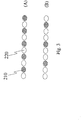
- the belt layer 107' comprises a first elongated element 210 and a second elongated element 220 helically wound in a substantially circumferential direction.
- the belt layer 107' comprises one turn of a first elongated element 210 alternate, along the axial width of the crossed belt plies, with one turn of a second elongated element 220.
- said elongated elements are arranged from 0° to 5° with respect to the equatorial plane of the tyre.
- the alternated sequence of the turns of said first 210 and second 220 elongated elements is constant along the axial development of the belt layer 107' and is equal to 1:1.
- Figure 2 shows a further embodiment of the present invention according to which the rigidity of the belt layer 107 of the present invention changes along the axial width thereof by varying the alternate sequence of the turns of said first 210 and second 220 elongated elements.
- the ratio of the first elongated element density to the second elongated element density along the axial width of the belt layer is not constant.
- the embodiment of Figure 2 shows that in the axial end portions of the belt layer 107 the density of the first elongated element 210 (i.e. the hybrid cord) is higher than in the central portion of the layer, i.e. in the portion which is astride of the equatorial plane of the tyre.
- the alternated sequence of the turns of the first and second elongated elements in the belt layer 107 is 2:1 in the axial end portions of said layer and is 1:1 in the central portion.
- the first elongated element 210 is a hybrid cord comprising at least a high elastic modulus filament and a low elastic modulus filament which are twisted together.
- the high elastic modulus filament of the hybrid cord has a load at an extension of 1% (LASE 1%) greater than or equal to 3 cN/dTex, preferably from 4 cN/dTex to 7 cN/dTex.
- the high elastic modulus filament of the hybrid cord is selected from: aromatic polyamide fiber, high modulus polyester fibers (e.g. polyethylene naphthalate - PEN), polyvinyl alcohol fiber, carbon fiber.
- the low elastic modulus filament of the hybrid cord has a load at an extension of 5% (LASE 5%) lower than or equal to 5 cN/dTex, preferably from 1 cN/dTex to 4 cN/dTex.
- the low elastic modulus filament of the hybrid cord is selected from: nylon fiber, low modulus polyester fibers (e.g. polyethylene terephthalate - PET), vinylon fiber.
- the hybrid cord has a load at an extension of 5% (LASE 5%) greater than 70 N, preferably greater than 75, even more preferably from 80 N to 150 N.
- LASE 5% 5%
- the hybrid cord is formed by aramidic fiber and rayon fiber.
- the hybrid cord is formed of two distinct filaments, i.e. a high elastic modulus filament is twisted together with a low elastic modulus filament.
- the hybrid cord is formed of three filaments, i.e. two high elastic modulus filaments twisted together with one low elastic modulus filament or one high elastic modulus filament twisted together with two low elastic modulus filaments.
- the filaments of the hybrid cord have a count from 400 dTex (this measure unit is the weight in grams corresponding to 10,000 m of fiber) to 3,000 dTex, preferably from 800 dTex to 2,200 dTex.
- the hybrid cord twist is from 100 tpm (turn per meter) to 600 tpm, preferably from 200 tpm to 400 tpm.
- the belt layer further comprises a second elongated element.
- the second elongated element is a cord.
- said cord consists of two or three filaments.
- suitable combinations for the obtainment of said cords are: two yarns twisted together, one or more yarns twisted with one or more steel or textile monofilaments.
- said second elongated element is a steel or textile monofilament.
- said second elongated element is a yarn.
- the second elongated element has a load at an extension of 5% (LASE 5%) lower than 70 N, preferably from 25 N to 50 N.
- the second elongated element is selected from: nylon fiber, polyester fiber, vinylon fiber, polyethylene terephthalate, a preformed steel cord.
- a preformed steel cord is a steel cord which is plastically deformed, according to any method known in the art, in such a way that the longitudinal extension of said cord has an undulating form.
- undulating form is understood as indicating any form which is not straight.
- undulating forms are regarded as including, for example, sinusoidal, helical and zigzag forms.
- a preforming according to substantially sinusoidal undulations is particularly preferred.
- said sinusoidal undulations have a wavelength of between 2.5 mm and 30 mm, and more preferably between 5 mm and 25 mm.
- said sinusoidal undulations have a wave amplitude of between 0.12 mm and 1 mm.
- the filament(s) of the second elongated element has (have) a count from 400 dTex to 3,000 dTex, preferably from 800 dTex to 2,200 dTex.
- the diameter of the filament(s) is (are) from 0.1 mm to 0.4 mm, preferably from 0.12 mm to 0.35 mm.
- the filaments of this cord have all the same diameter.
- said filaments have diameters different from each other.
- the ratio between the density of the first elongated element and the density of the second elongated element in the belt layer ranges (in percentage) from 10/90 to 90/10, preferably from 50/50 to 80/20.
- the alternated sequence of the turns respectively of the first and second elongated elements in the belt layer is: 1:1; 2:1; 2:2; 3:1; 4:1.
- Figure 3 shows two examples A, B of sequences of turns of said first 210 and second 220 elongated elements in the belt layer of the present invention.
- sequence A corresponds to a uniform and constant alternation in the belt layer of one turn of a first elongated element 210 and one turn of a second elongated element 220
- sequence B corresponds to a uniform and constant alternation in the belt layer of two turns of a first elongated element 210 and one turn of a second elongated element 220.
- the belt layer of the present invention is employed in pneumatic tyres which are suitable for running at high speeds.
- the belt layer of the present invention is particularly suitable for "HP" (High Performance) or "UHP” (Ultra High Performance) tyres, i.e. for tyres belonging to Classes “H” and “V” (maximum speed over 210 Km/h) and to Classes “W” and “Y” (maximum speed over 240 Km/h). Furthermore, the present invention is suitable for tyres whose maximum speed is over 300 km/h.
- the tyre of the invention has a H/C ratio, of the height of the right cross-section to the maximum width of the section, ranging between 0.65 and 2.0.
- the tyre of the present invention is a tyre having very low cross-section, e.g. with a ratio H/C of between 0.25 and 0.65, preferably from 0.25 and 0.45.
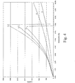
- the curve 5 of the curve represents the elongation curve of the strip-like band 5) which comprises only the low elastic modulus cords C, i.e. the cords formed of one Nylon filament while the curve 4 represents the elongation curve of the strip-like band 4) which comprises only the low elastic modulus cords B, i.e. the cords formed of two Nylon filaments.
- the curve 1 of the curve represents the elongation curve of the strip-like band 1) which comprises only the hybrid cords A, said curve 1 showing that the elastic modulus of the strip-like band 1) is higher than that of the strip-like band 4).
- the curves 2 and 3 - referring to the strip-like bands of the invention - lie between the curves 1 and 5, i.e. the strip-like bands of the present invention have an elastic modulus which is intermediate between that of the strip-like band comprising only hybrid cords and that of the strip-like band comprising only Nylon cords.
- the curve of Figure 4 shows that it is possible to modify the stiffness of the strip-like band by modifying the ratio of the hybrid cords and the Nylon cords present in the same band.
- the tyres 1 to 5 had identical structural elements (e.g. identical carcass, crossed belt plies, bead cores, tread band) but for the 0° belt layer positioned radially external to the crossed belt plies, said 0° belt layer having been produced by using the different strip-like bands of Example 1.
- the 0° belt layers of the tyres 2 to 5 consisted of two layers obtained by spirally winding twice the strip-like bands 2) to 5) respectively, while the 0° belt layer of the tyre 1 consisted of only one layer obtained by spirally winding twice the strip-like band 1).
- the tyre was rotated against a road wheel at increasing speeds.
- the road wheel was rotated from 20 km/h to 260 km/h; the speed was incremented of 20 km/h every two minutes.
- the tyre rolling radius (height) was measured by calculating the difference between the tip speeds of the road wheel and the tyre respectively, and the tyre diameter variation was calculated (as the difference in percentage between the tyre diameter values at the two distinct speeds mentioned above) in order to measure the growth of the tyre while increasing the speed. Said test was used in order to evaluate the lifting phenomenon.
- the tyre was rotated against a road wheel at increasing speeds.
- the road wheel was rotated at 240 km/h for 1 minute and successively the speed was incremented of 10 km/h every ten minutes.
- the test was stopped when the failure of the tyre occured, said failure being due, for instance, to breakage of the cords, chunkings, tearing of a block, carcass plies detachment, belt plies detachment, blister formation.
- the reference index was 100 and said value was incremented of one single point every time period (e.g. 1 minute) which passed without the occurrence of the tyre failure. Furthermore, said value was incremented of three points at each speed increasing.
- the test was conducted at different speeds on straight roads having different surfaces (e.g. flat and regular surface and undulated surface). For instance, the driver evaluated in the different test conditions the steering corrections (if any) necessary to keep a straight path, the capacity of the tyre to overcome any upward projecting bumps of the road, the rigidity of the steering-wheel.
- the handling tests were conducted on a track and the test driver simulated some characteristic manoeuvring (change of lane, entering a bend, leaving a bend, for example) carried out at constant speed, in acceleration and in deceleration. Then the test driver judged the tyre behaviour and assigned a score depending on the tyre performance during said manoeuvring.
- the handling is divided into two voices (soft handling and hard handling) depending on the type of manoeuvre carried out by the test driver.
- the soft handling relates to the use of the tyre under normal running conditions, i.e. in conditions of normal speed and good transversal grip.
- the hard handling tests describe the behaviour of the tyre at the limit of adherence, i.e. under extreme driving conditions. In the latter case the test driver executes manoeuvres which an average driver might be forced to carry out in the case of unforeseen and hazardous circumstances: sharp steering at high speed, sudden changing of lanes to avoid obstacles, sudden braking and the like.
- the test was carried out along a straight section equipped with microphones.
- the car entered the section at a predefined speed of entry, after which the engine was switched off and the noise outside the car in neutral gear was measured.
- the comfort was evaluated in terms of the overall sensations perceived by the test driver compared to the capacity for the tyre to absorb the roughness of the road surface.
- the comfort test was carried out in the conditions prescribed by the standard RE01.
- the vehicle used for the tests was a Porsche Carrera 996 fitted with the tyres of the invention.
- the tyres were fitted on standard rims and were inflated to the nominal operating pressure.
- the results of said tests are expressed by means of an evaluation scale representing the subjective opinion expressed by a test driver through a point system.
- the values reproduced in the following table represent a mean value between those obtained in several test sessions (5 - 6 tests, for example) and given by several test drivers.
- Table 2 Straight running Soft handling Hard handling Comfort Tyre 1 (comparative) 100 100 100 85 Tyre 2 ( invention) 85 90 85 100 Tyre 3 (invention) 90 100 90 100 Tyre 4 (comparati ve) 85 90 80 90 Tyre 5 (comparative) 85 90 80 85
- the tyres of the present invention exhibit limited tyre growth, rather good high speed durability and good overall outdoor results, among which a remarkable and very important improvement is obtained with reference to the comfort.
- the belt layer of the present invention succeeds in this aim to be achieved.
Landscapes
- Engineering & Computer Science (AREA)
- Mechanical Engineering (AREA)
- Tires In General (AREA)
Applications Claiming Priority (1)
| Application Number | Priority Date | Filing Date | Title |
|---|---|---|---|
| PCT/EP2003/006495 WO2005002884A1 (en) | 2003-06-19 | 2003-06-19 | Tyre with improved belt structure |
Publications (2)
| Publication Number | Publication Date |
|---|---|
| EP1636052A1 EP1636052A1 (en) | 2006-03-22 |
| EP1636052B1 true EP1636052B1 (en) | 2018-08-08 |
Family
ID=33560718
Family Applications (1)
| Application Number | Title | Priority Date | Filing Date |
|---|---|---|---|
| EP03817322.5A Expired - Lifetime EP1636052B1 (en) | 2003-06-19 | 2003-06-19 | Tyre with improved belt structure |
Country Status (6)
| Country | Link |
|---|---|
| US (1) | US9346320B2 (enExample) |
| EP (1) | EP1636052B1 (enExample) |
| JP (1) | JP4564919B2 (enExample) |
| AU (1) | AU2003246563A1 (enExample) |
| BR (1) | BR0318336B1 (enExample) |
| WO (1) | WO2005002884A1 (enExample) |
Families Citing this family (24)
| Publication number | Priority date | Publication date | Assignee | Title |
|---|---|---|---|---|
| WO2007002266A2 (en) * | 2005-06-22 | 2007-01-04 | Purdue Research Foundation | Structures with integral life-sensing capability |
| JP4309466B2 (ja) * | 2006-09-22 | 2009-08-05 | 横浜ゴム株式会社 | 空気入りラジアルタイヤ |
| US20090090447A1 (en) * | 2007-10-05 | 2009-04-09 | Baldwin Jr Donald William | Tire cord reinforcement |
| BRPI0803609A2 (pt) * | 2007-10-05 | 2009-06-16 | Goodyear Tire & Rubber | reforço de cordão de pneumático |
| KR20150074024A (ko) * | 2012-10-18 | 2015-07-01 | 코드사 글로벌 엔두스트리옐 이플릭 베 코드 베지 사나위 베 티카레트 아노님 시르케티 | 레디얼 차량 타이어용 보강 벨트 패키지 |
| JP2014108675A (ja) * | 2012-11-30 | 2014-06-12 | Toyo Tire & Rubber Co Ltd | 空気入りラジアルタイヤ |
| EP2890571B1 (en) * | 2012-12-25 | 2019-08-21 | Kordsa Teknik Tekstil A.S | A tire reinforcement material |
| CN104968847B (zh) * | 2013-01-29 | 2017-09-26 | 大陆轮胎德国有限公司 | 用于由弹性材料制成的物品的、优选用于车辆充气轮胎的加强层以及车辆充气轮胎 |
| US10040323B2 (en) | 2013-03-15 | 2018-08-07 | Bridgestone Americas Tire Operations, Llc | Pneumatic tire with bead reinforcing elements at least partially formed from carbon fibers |
| CN105517814B (zh) | 2013-08-08 | 2018-01-30 | 倍耐力轮胎股份公司 | 提高用于车辆车轮的轮胎的性能的方法和用于车辆车轮的轮胎 |
| CN105745088B (zh) | 2013-12-04 | 2017-11-17 | 横滨橡胶株式会社 | 充气轮胎 |
| DE102014220518A1 (de) * | 2014-10-09 | 2016-04-14 | Continental Reifen Deutschland Gmbh | Fahrzeugluftreifen aufweisend eine Gürtelbandage |
| US11827064B2 (en) | 2015-08-31 | 2023-11-28 | The Goodyear Tire & Rubber Company | Reduced weight aircraft tire |
| JP6260598B2 (ja) * | 2015-09-30 | 2018-01-17 | 横浜ゴム株式会社 | 空気入りタイヤ及びその製造方法 |
| CN108349308A (zh) | 2016-10-13 | 2018-07-31 | 科德沙技术纺织品股份公司 | 新型尼龙6,6冠带层 |
| WO2018070952A1 (en) | 2016-10-13 | 2018-04-19 | Kordsa Teknik Tekstil Anonim Sirketi | Cap ply strip with different nylon 6,6 reinforcement constructions |
| JP6319409B1 (ja) * | 2016-12-09 | 2018-05-09 | 横浜ゴム株式会社 | 空気入りタイヤ |
| CN113661075B (zh) * | 2019-04-17 | 2025-10-03 | 倍耐力轮胎股份公司 | 混合帘线和具有这种帘线的轮胎 |
| WO2021130832A1 (en) * | 2019-12-24 | 2021-07-01 | Compagnie Generale Des Etablissements Michelin | A tire for improved noise performance |
| JP7572167B2 (ja) * | 2020-05-26 | 2024-10-23 | Toyo Tire株式会社 | 空気入りタイヤ |
| US20230064368A1 (en) * | 2021-08-25 | 2023-03-02 | The Goodyear Tire & Rubber Company | Pneumatic aviation tire |
| JP7753058B2 (ja) * | 2021-11-02 | 2025-10-14 | Toyo Tire株式会社 | 空気入りタイヤ |
| JP2023068374A (ja) * | 2021-11-02 | 2023-05-17 | Toyo Tire株式会社 | 空気入りタイヤ |
| JP7753059B2 (ja) * | 2021-11-02 | 2025-10-14 | Toyo Tire株式会社 | 空気入りタイヤ |
Citations (3)
| Publication number | Priority date | Publication date | Assignee | Title |
|---|---|---|---|---|
| EP0540202A1 (en) * | 1991-10-14 | 1993-05-05 | Sumitomo Rubber Industries Limited | Motorcycle tyre |
| EP0756949A1 (en) * | 1995-08-01 | 1997-02-05 | PIRELLI COORDINAMENTO PNEUMATICI S.p.A. | High-transverse-curvature tyre, in particular for a two-wheeled vehicle |
| EP0790143A1 (en) * | 1996-02-15 | 1997-08-20 | Sumitomo Rubber Industries Limited | Pneumatic radial tyre |
Family Cites Families (20)
| Publication number | Priority date | Publication date | Assignee | Title |
|---|---|---|---|---|
| CA1046914A (en) * | 1974-03-14 | 1979-01-23 | Claude H. Allard | Tire cord fabrics for belts of belted pneumatic tires |
| IT1067771B (it) * | 1976-11-05 | 1985-03-16 | Pirelli | Perfezionamento al procedimento di fabbricazione di pneumatici |
| US4155394A (en) * | 1977-08-29 | 1979-05-22 | The Goodyear Tire & Rubber Company | Tire cord composite and pneumatic tire |
| DE3855488T2 (de) * | 1987-06-18 | 1997-01-09 | Sumitomo Rubber Ind | Einrichtung zur Herstellung eines Gürtels für Radial-Reifen |
| JPH01204802A (ja) * | 1988-02-12 | 1989-08-17 | Yokohama Rubber Co Ltd:The | 空気入りラジアルタイヤ |
| US4869307A (en) * | 1988-03-17 | 1989-09-26 | The Goodyear Tire & Rubber Company | Pneumatic tire and method for making same |
| JP2757940B2 (ja) * | 1988-03-28 | 1998-05-25 | 住友ゴム工業株式会社 | 空気入りタイヤ |
| JPH04154404A (ja) * | 1990-10-18 | 1992-05-27 | Toyo Tire & Rubber Co Ltd | ベルト補強層を有するラジアルタイヤ |
| JP2628938B2 (ja) * | 1991-02-05 | 1997-07-09 | 住友ゴム工業株式会社 | 空気入りタイヤ |
| DE4216695A1 (de) * | 1992-05-20 | 1993-12-02 | Sp Reifenwerke Gmbh | Fahrzeugreifen mit Verstärkungseinlagen |
| JP3294378B2 (ja) * | 1993-04-21 | 2002-06-24 | 住友ゴム工業株式会社 | 空気入りタイヤ |
| JPH06305304A (ja) * | 1993-04-23 | 1994-11-01 | Sumitomo Rubber Ind Ltd | 空気入りタイヤ |
| JPH07215011A (ja) | 1994-01-31 | 1995-08-15 | Bridgestone Corp | 空気入りラジアルタイヤ |
| DE69509323T2 (de) * | 1994-08-23 | 1999-08-26 | Dunlop Gmbh | Fahrzeug-Luftreifen |
| FR2734764A1 (fr) * | 1995-05-30 | 1996-12-06 | Michelin & Cie | Pneumatique avec une nappe de renforcement a elements circonferentiels. |
| DE19526408A1 (de) * | 1995-07-19 | 1997-01-23 | Sp Reifenwerke Gmbh | Fahrzeugluftreifen |
| ATE250517T1 (de) | 1997-12-30 | 2003-10-15 | Pirelli | Luftreifen für fahrzeugräder |
| EP0928680B1 (en) | 1997-12-30 | 2003-03-12 | Pirelli Pneumatici Societa' Per Azioni | A method for making tyres for vehicle wheels |
| WO2001042032A1 (en) * | 1999-12-07 | 2001-06-14 | Michelin Recherche Et Technique S.A. | Pneumatic tire with improved endurance |
| JP2002059707A (ja) * | 2000-08-23 | 2002-02-26 | Bridgestone Corp | 空気入りタイヤ及び空気入りタイヤの製造方法 |
-
2003
- 2003-06-19 US US10/559,182 patent/US9346320B2/en active Active
- 2003-06-19 WO PCT/EP2003/006495 patent/WO2005002884A1/en not_active Ceased
- 2003-06-19 AU AU2003246563A patent/AU2003246563A1/en not_active Abandoned
- 2003-06-19 EP EP03817322.5A patent/EP1636052B1/en not_active Expired - Lifetime
- 2003-06-19 BR BRPI0318336-0B1A patent/BR0318336B1/pt active IP Right Grant
- 2003-06-19 JP JP2005503301A patent/JP4564919B2/ja not_active Expired - Lifetime
Patent Citations (3)
| Publication number | Priority date | Publication date | Assignee | Title |
|---|---|---|---|---|
| EP0540202A1 (en) * | 1991-10-14 | 1993-05-05 | Sumitomo Rubber Industries Limited | Motorcycle tyre |
| EP0756949A1 (en) * | 1995-08-01 | 1997-02-05 | PIRELLI COORDINAMENTO PNEUMATICI S.p.A. | High-transverse-curvature tyre, in particular for a two-wheeled vehicle |
| EP0790143A1 (en) * | 1996-02-15 | 1997-08-20 | Sumitomo Rubber Industries Limited | Pneumatic radial tyre |
Also Published As
| Publication number | Publication date |
|---|---|
| JP2006527679A (ja) | 2006-12-07 |
| WO2005002884A1 (en) | 2005-01-13 |
| BR0318336A (pt) | 2006-07-11 |
| US20060237113A1 (en) | 2006-10-26 |
| US9346320B2 (en) | 2016-05-24 |
| EP1636052A1 (en) | 2006-03-22 |
| BR0318336B1 (pt) | 2013-12-24 |
| AU2003246563A1 (en) | 2005-01-21 |
| JP4564919B2 (ja) | 2010-10-20 |
Similar Documents
| Publication | Publication Date | Title |
|---|---|---|
| EP1636052B1 (en) | Tyre with improved belt structure | |
| EP1559588B1 (en) | Radial tire with circumferential spirally wound belt layer | |
| EP1066989B1 (en) | Pneumatic tyre | |
| US5404924A (en) | Motorcycle tire with spirally wound belt | |
| EP1648720B1 (en) | Pneumatic tyre having a reinforced bead structure | |
| KR100572048B1 (ko) | 높은 횡곡률 계수를 갖는, 특히 2륜 차량용 타이어 | |
| JPH0640210A (ja) | 自動二輪車用タイヤ | |
| US8578989B2 (en) | Motor vehicle tire | |
| EP0855289B1 (en) | Motorcycle tyre | |
| US4854360A (en) | Pneumatic radial tire arrangement for vehicle | |
| EP0465188B2 (en) | Passenger radial tyre | |
| JP3964495B2 (ja) | ゴムとスチ−ル補強材との複合体、及びこれをベルト部に使用した空気入りラジアルタイヤ | |
| JP3121438B2 (ja) | 自動二輪車用ラジアルタイヤ | |
| US6244315B1 (en) | Tyre with high transverse curvature coefficient in particular for a two-wheeled vehicle | |
| JP2966488B2 (ja) | 空気入りラジアルタイヤ | |
| JP4471242B2 (ja) | 空気入りラジアルタイヤ | |
| JPH1178410A (ja) | 乗用車用空気入りラジアル・タイヤ | |
| JP2002096606A (ja) | タイヤ | |
| JP4127887B2 (ja) | 自動二輪車用空気入りタイヤ | |
| JPH02158404A (ja) | 改良タイヤ | |
| CN113928060B (zh) | 轮胎 | |
| JP3308029B2 (ja) | 自動二輪車用タイヤ | |
| RU2343079C2 (ru) | Пневматическая шина с усиленной конструкцией борта | |
| JP2001055006A (ja) | 空気入りラジアルタイヤ | |
| JP2000264013A (ja) | 二輪自動車用空気入りタイヤ |
Legal Events
| Date | Code | Title | Description |
|---|---|---|---|
| PUAI | Public reference made under article 153(3) epc to a published international application that has entered the european phase |
Free format text: ORIGINAL CODE: 0009012 |
|
| 17P | Request for examination filed |
Effective date: 20051130 |
|
| AK | Designated contracting states |
Kind code of ref document: A1 Designated state(s): AT BE BG CH CY CZ DE DK EE ES FI FR GB GR HU IE IT LI LU MC NL PT RO SE SI SK TR |
|
| RAP1 | Party data changed (applicant data changed or rights of an application transferred) |
Owner name: PIRELLI TYRE S.P.A. |
|
| DAX | Request for extension of the european patent (deleted) | ||
| 17Q | First examination report despatched |
Effective date: 20120921 |
|
| RAP1 | Party data changed (applicant data changed or rights of an application transferred) |
Owner name: PIRELLI TYRE S.P.A. |
|
| RIC1 | Information provided on ipc code assigned before grant |
Ipc: B60C 9/22 20060101AFI20151030BHEP Ipc: B60C 9/20 20060101ALI20151030BHEP |
|
| STAA | Information on the status of an ep patent application or granted ep patent |
Free format text: STATUS: EXAMINATION IS IN PROGRESS |
|
| GRAP | Despatch of communication of intention to grant a patent |
Free format text: ORIGINAL CODE: EPIDOSNIGR1 |
|
| STAA | Information on the status of an ep patent application or granted ep patent |
Free format text: STATUS: GRANT OF PATENT IS INTENDED |
|
| INTG | Intention to grant announced |
Effective date: 20180319 |
|
| GRAS | Grant fee paid |
Free format text: ORIGINAL CODE: EPIDOSNIGR3 |
|
| GRAA | (expected) grant |
Free format text: ORIGINAL CODE: 0009210 |
|
| STAA | Information on the status of an ep patent application or granted ep patent |
Free format text: STATUS: THE PATENT HAS BEEN GRANTED |
|
| AK | Designated contracting states |
Kind code of ref document: B1 Designated state(s): AT BE BG CH CY CZ DE DK EE ES FI FR GB GR HU IE IT LI LU MC NL PT RO SE SI SK TR |
|
| REG | Reference to a national code |
Ref country code: GB Ref legal event code: FG4D |
|
| REG | Reference to a national code |
Ref country code: CH Ref legal event code: EP Ref country code: AT Ref legal event code: REF Ref document number: 1026554 Country of ref document: AT Kind code of ref document: T Effective date: 20180815 |
|
| REG | Reference to a national code |
Ref country code: IE Ref legal event code: FG4D |
|
| REG | Reference to a national code |
Ref country code: DE Ref legal event code: R096 Ref document number: 60351388 Country of ref document: DE |
|
| REG | Reference to a national code |
Ref country code: RO Ref legal event code: EPE |
|
| REG | Reference to a national code |
Ref country code: NL Ref legal event code: MP Effective date: 20180808 |
|
| REG | Reference to a national code |
Ref country code: AT Ref legal event code: MK05 Ref document number: 1026554 Country of ref document: AT Kind code of ref document: T Effective date: 20180808 |
|
| PG25 | Lapsed in a contracting state [announced via postgrant information from national office to epo] |
Ref country code: BG Free format text: LAPSE BECAUSE OF FAILURE TO SUBMIT A TRANSLATION OF THE DESCRIPTION OR TO PAY THE FEE WITHIN THE PRESCRIBED TIME-LIMIT Effective date: 20181108 Ref country code: NL Free format text: LAPSE BECAUSE OF FAILURE TO SUBMIT A TRANSLATION OF THE DESCRIPTION OR TO PAY THE FEE WITHIN THE PRESCRIBED TIME-LIMIT Effective date: 20180808 Ref country code: SE Free format text: LAPSE BECAUSE OF FAILURE TO SUBMIT A TRANSLATION OF THE DESCRIPTION OR TO PAY THE FEE WITHIN THE PRESCRIBED TIME-LIMIT Effective date: 20180808 Ref country code: AT Free format text: LAPSE BECAUSE OF FAILURE TO SUBMIT A TRANSLATION OF THE DESCRIPTION OR TO PAY THE FEE WITHIN THE PRESCRIBED TIME-LIMIT Effective date: 20180808 Ref country code: FI Free format text: LAPSE BECAUSE OF FAILURE TO SUBMIT A TRANSLATION OF THE DESCRIPTION OR TO PAY THE FEE WITHIN THE PRESCRIBED TIME-LIMIT Effective date: 20180808 Ref country code: GR Free format text: LAPSE BECAUSE OF FAILURE TO SUBMIT A TRANSLATION OF THE DESCRIPTION OR TO PAY THE FEE WITHIN THE PRESCRIBED TIME-LIMIT Effective date: 20181109 |
|
| PG25 | Lapsed in a contracting state [announced via postgrant information from national office to epo] |
Ref country code: ES Free format text: LAPSE BECAUSE OF FAILURE TO SUBMIT A TRANSLATION OF THE DESCRIPTION OR TO PAY THE FEE WITHIN THE PRESCRIBED TIME-LIMIT Effective date: 20180808 |
|
| PG25 | Lapsed in a contracting state [announced via postgrant information from national office to epo] |
Ref country code: EE Free format text: LAPSE BECAUSE OF FAILURE TO SUBMIT A TRANSLATION OF THE DESCRIPTION OR TO PAY THE FEE WITHIN THE PRESCRIBED TIME-LIMIT Effective date: 20180808 Ref country code: CZ Free format text: LAPSE BECAUSE OF FAILURE TO SUBMIT A TRANSLATION OF THE DESCRIPTION OR TO PAY THE FEE WITHIN THE PRESCRIBED TIME-LIMIT Effective date: 20180808 |
|
| REG | Reference to a national code |
Ref country code: DE Ref legal event code: R097 Ref document number: 60351388 Country of ref document: DE |
|
| PG25 | Lapsed in a contracting state [announced via postgrant information from national office to epo] |
Ref country code: SK Free format text: LAPSE BECAUSE OF FAILURE TO SUBMIT A TRANSLATION OF THE DESCRIPTION OR TO PAY THE FEE WITHIN THE PRESCRIBED TIME-LIMIT Effective date: 20180808 Ref country code: DK Free format text: LAPSE BECAUSE OF FAILURE TO SUBMIT A TRANSLATION OF THE DESCRIPTION OR TO PAY THE FEE WITHIN THE PRESCRIBED TIME-LIMIT Effective date: 20180808 |
|
| PLBE | No opposition filed within time limit |
Free format text: ORIGINAL CODE: 0009261 |
|
| STAA | Information on the status of an ep patent application or granted ep patent |
Free format text: STATUS: NO OPPOSITION FILED WITHIN TIME LIMIT |
|
| 26N | No opposition filed |
Effective date: 20190509 |
|
| PG25 | Lapsed in a contracting state [announced via postgrant information from national office to epo] |
Ref country code: SI Free format text: LAPSE BECAUSE OF FAILURE TO SUBMIT A TRANSLATION OF THE DESCRIPTION OR TO PAY THE FEE WITHIN THE PRESCRIBED TIME-LIMIT Effective date: 20180808 |
|
| PG25 | Lapsed in a contracting state [announced via postgrant information from national office to epo] |
Ref country code: MC Free format text: LAPSE BECAUSE OF FAILURE TO SUBMIT A TRANSLATION OF THE DESCRIPTION OR TO PAY THE FEE WITHIN THE PRESCRIBED TIME-LIMIT Effective date: 20180808 |
|
| REG | Reference to a national code |
Ref country code: CH Ref legal event code: PL |
|
| REG | Reference to a national code |
Ref country code: BE Ref legal event code: MM Effective date: 20190630 |
|
| PG25 | Lapsed in a contracting state [announced via postgrant information from national office to epo] |
Ref country code: TR Free format text: LAPSE BECAUSE OF FAILURE TO SUBMIT A TRANSLATION OF THE DESCRIPTION OR TO PAY THE FEE WITHIN THE PRESCRIBED TIME-LIMIT Effective date: 20180808 |
|
| PG25 | Lapsed in a contracting state [announced via postgrant information from national office to epo] |
Ref country code: IE Free format text: LAPSE BECAUSE OF NON-PAYMENT OF DUE FEES Effective date: 20190619 |
|
| PG25 | Lapsed in a contracting state [announced via postgrant information from national office to epo] |
Ref country code: LI Free format text: LAPSE BECAUSE OF NON-PAYMENT OF DUE FEES Effective date: 20190630 Ref country code: CH Free format text: LAPSE BECAUSE OF NON-PAYMENT OF DUE FEES Effective date: 20190630 Ref country code: LU Free format text: LAPSE BECAUSE OF NON-PAYMENT OF DUE FEES Effective date: 20190619 Ref country code: BE Free format text: LAPSE BECAUSE OF NON-PAYMENT OF DUE FEES Effective date: 20190630 |
|
| PG25 | Lapsed in a contracting state [announced via postgrant information from national office to epo] |
Ref country code: PT Free format text: LAPSE BECAUSE OF FAILURE TO SUBMIT A TRANSLATION OF THE DESCRIPTION OR TO PAY THE FEE WITHIN THE PRESCRIBED TIME-LIMIT Effective date: 20181208 |
|
| PG25 | Lapsed in a contracting state [announced via postgrant information from national office to epo] |
Ref country code: CY Free format text: LAPSE BECAUSE OF FAILURE TO SUBMIT A TRANSLATION OF THE DESCRIPTION OR TO PAY THE FEE WITHIN THE PRESCRIBED TIME-LIMIT Effective date: 20180808 |
|
| PG25 | Lapsed in a contracting state [announced via postgrant information from national office to epo] |
Ref country code: HU Free format text: LAPSE BECAUSE OF FAILURE TO SUBMIT A TRANSLATION OF THE DESCRIPTION OR TO PAY THE FEE WITHIN THE PRESCRIBED TIME-LIMIT; INVALID AB INITIO Effective date: 20030619 |
|
| PGFP | Annual fee paid to national office [announced via postgrant information from national office to epo] |
Ref country code: RO Payment date: 20220609 Year of fee payment: 20 Ref country code: IT Payment date: 20220621 Year of fee payment: 20 Ref country code: GB Payment date: 20220628 Year of fee payment: 20 |
|
| PGFP | Annual fee paid to national office [announced via postgrant information from national office to epo] |
Ref country code: FR Payment date: 20220627 Year of fee payment: 20 |
|
| PGFP | Annual fee paid to national office [announced via postgrant information from national office to epo] |
Ref country code: DE Payment date: 20220629 Year of fee payment: 20 |
|
| REG | Reference to a national code |
Ref country code: DE Ref legal event code: R071 Ref document number: 60351388 Country of ref document: DE |
|
| REG | Reference to a national code |
Ref country code: GB Ref legal event code: PE20 Expiry date: 20230618 |
|
| PG25 | Lapsed in a contracting state [announced via postgrant information from national office to epo] |
Ref country code: GB Free format text: LAPSE BECAUSE OF EXPIRATION OF PROTECTION Effective date: 20230618 |