EP1632986A2 - Lampe incandescente à halogène - Google Patents
Lampe incandescente à halogène Download PDFInfo
- Publication number
- EP1632986A2 EP1632986A2 EP05012058A EP05012058A EP1632986A2 EP 1632986 A2 EP1632986 A2 EP 1632986A2 EP 05012058 A EP05012058 A EP 05012058A EP 05012058 A EP05012058 A EP 05012058A EP 1632986 A2 EP1632986 A2 EP 1632986A2
- Authority
- EP
- European Patent Office
- Prior art keywords
- vessel
- halogen incandescent
- incandescent lamp
- lamp according
- exit window
- Prior art date
- Legal status (The legal status is an assumption and is not a legal conclusion. Google has not performed a legal analysis and makes no representation as to the accuracy of the status listed.)
- Withdrawn
Links
Images

Classifications
-
- H—ELECTRICITY
- H01—ELECTRIC ELEMENTS
- H01K—ELECTRIC INCANDESCENT LAMPS
- H01K1/00—Details
- H01K1/28—Envelopes; Vessels
- H01K1/32—Envelopes; Vessels provided with coatings on the walls; Vessels or coatings thereon characterised by the material thereof
- H01K1/325—Reflecting coating
Definitions
- the invention relates to a halogen incandescent lamp according to the preamble of claim 1.
- Such a side reflector lamp is described on the Internet domain www.osram.de under the product name "MINISTAR®".
- a peripheral portion of a lamp vessel is provided with a reflective coating so that a laterally arranged light emission window remains on the lamp vessel, which makes it possible, for example, to use this lamp as a downlight, the lamp being mounted in the horizontal direction.
- Such reflector lamps are constructed extremely compact and therefore require a minimum installation space during installation.
- Such reflector lamps consist of a reflector which is formed by a parabolic or ellipsoidal glass dome and a halogen incandescent lamp which is fixed in the optical axis of the reflector.
- the compact halogen incandescent lamps with a reflector integrated in the lamp vessel can be improved with regard to the emitted luminous flux, in particular when a luminous body accommodated in the lamp vessel is formed with at least two filament sections. Illuminants with two filament sections are used, for example, in the case of halogen incandescent lamps intended for operation on mains voltage, as described in European Patent EP 0 446 460 B1.
- the invention has for its object to provide a halogen incandescent lamp with side reflector, in which the illumination of a predetermined area is improved.
- the halogen incandescent lamp according to the invention has a lamp vessel sealed on one side, in which at least one luminous element is accommodated, wherein a section of the lamp vessel is designed as a side reflector, which extends only over a partial area of the lamp vessel periphery, so that a light exit window remains.
- the vessel section acting as a reflector bulges away from the comparatively flat or flat light exit window, viewed in cross-section.
- the mean radius of curvature of the light exit window is greater than the average radius of curvature of the vaulting towards the rear, acting as a reflector vessel section executed.
- cylindrically executed lamp vessel receives in the region of the reflector a curvature, which is performed for example approximately parabolic or ellipsoidal and thus optimized in terms of reflection properties, so that emerging from the light exit window luminous flux over conventional solutions increases and a targeted illumination of a predetermined range is possible.
- the width seen in the cross section of the light exit window is greater than the depth of the designed as a reflector vessel portion.
- the invention can be applied particularly advantageously in a halogen incandescent lamp, in which the luminous element is designed with two spiral arms.
- a constriction extending in the direction of the light exit window is formed in a vertex of the bulge of the reflective vessel section, so that a rear wall of the vessel section is retracted kidney-shaped.
- the lamp bulb formed as a reflector is provided with two Einmuldungen whose geometry is designed so that the output of each helical arm light radiation is reflected in an optimal manner.
- this constriction is arranged in a plane of symmetry to the helical arms.
- a holding nub is preferably formed in the region of the emission window and a retaining nub arranged diametrically therewith in the region of the rear constriction.
- the filament is carried out with two preferably inclined spiral arms, which are connected to each other via a connecting part on which attack the holding nubs.
- the reflective vessel portion is provided with a coating which is preferably applied to the outer periphery of the lamp vessel.
- the sealed end of the lamp vessel is advantageously formed as a base, as described for example in European Patent EP 0 897 604 B1.
- The. Lamp vessel is in an embodiment of the invention via a circumferential chamfer in this base over.
- the base is preferably arranged closer to the vertex of the reflective vessel section than to the vertex of the light exit window.
- a pump stalk attachment for filling the halogen incandescent lamp can be arranged on a dome covering the reflective vessel section.
- the halogen incandescent lamp is designed for operation on mains voltage.
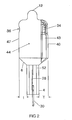
- Figures 1 to 3 show a designed for operation on mains voltage halogen incandescent lamp 1. In principle, however, the invention is also applicable to NV or MV halogen incandescent lamps.
- the halogen incandescent lamp 1 has, according to FIGS. 1 and 2, a lamp vessel 2 which is preferably made of quartz glass and on whose lower end section in FIG. 1 a base 4 is formed by a pinch seal which can be inserted into a socket (not shown). This base 4 is via a circumferential chamfer 6 in a piston 8 of the lamp vessel 2 via.
- the end portion of the lamp vessel 2 remote from the base 4 is formed by a dome 10 on which a pump stem extension 12 is formed.
- a luminous body 14 is arranged, which is executed in the described embodiment with two spiral arms 16, 18, which are connected to each other via a connecting part 20.
- the helical arms 16, 18 are inclined, so that their distance downwards, towards the base 4, increases.
- the two spiral arms 16, 18 go into power supply lines 22, 24, whose end portions are immersed in the base 4 formed by the pinch seal and are each connected to a molybdenum foil 26, 28, which are also embedded in the base 4. These are in turn connected to approximately U-shaped outer power supply, hereinafter referred to as contacts 30, 32, whose bent end portions are immersed in channels of the base 4 or embedded in these.
- the spiral arms 16, 18, the connecting part 20 and the two power supply lines 22, 24 are preferably made of tungsten.
- the holding nubs 34, 36 are each formed with an approximately elliptical cross section, the longitudinal axis of the horizontally arranged in Figure 1 region 38 of the connecting part 20 covers a maximum connection area between the elliptical end faces of the holding nubs 34, 36 and the connecting part 20th to achieve.
- a pumping tube is attached to the exhaust nozzle extension 12, through which the interior of the piston 8 is evacuated and filled with a halogen-containing filling gas. After filling, the pump tube is removed and the pump stem attachment 12 is sealed.
- the piston 8 is not designed with a cylindrical cross-section, as in the prior art described above, but has a view towards the observer in the illustration according to FIG facing light exit window 40, to which a backward, ie from the light exit window 40 wegölbender vessel portion 42 connects.
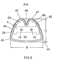
- the light exit window 40 passes over two rounded surface portions 43, 45 in the vaulted back to the vessel portion 42.
- a light-reflecting layer 44 for example, designed as a dichroic or silver or aluminum layer can be.
- the coating is indicated in Figure 2 by a shading.
- the light emission window 40 is not covered by this reflective layer 44.
- the wall regions of the vessel section 42 adjoining the light exit window 40 are curved approximately parabolically or ellipsoidally, wherein a constriction 46 is formed in the apex, through which the wall bulges approximately kidney-shaped back toward the light exit window 40.
- two curved reflection regions 48, 50 are formed, which are each associated with one of the helical arms 16, 18 and engage around these in sections at a distance.
- a partial reflector is formed by the reflection regions 48, 50, by which the light radiated by the associated helix arm 16, 18 is reflected in the direction of the exit window 40, so that the emission angle of the halogen lamp 1 is substantially sharper than with conventional lamps is and thus a uniform illumination of a predetermined area is made possible.
- the constriction 46 extends rearwardly practically over the entire height of the vessel portion 42 up to the chamfer 6, correspondingly, the two reflection regions 48, 50 extend over a range which is higher than the length of the two helical arms 16, 18.
- the lowest point of the constriction 46 seen in cross-section lies in a plane of symmetry between the two helical arms 16, 18, which runs perpendicular to the plane of the drawing in FIG.
- the width B of the exit window is greater than the depth U, ie, greater than the maximum distance between the light exit window 40 and the inwardly curved rear wall or the two apexes 47 of the vessel section 42.
- the cross-sectional shape of the piston 8 of the illustrated embodiment is also characterized in that in the view of Figure 3 the mean radius of curvature of the light exit window 40 is greater than that of the vessel portion 42 bulging toward the rear.
- the base 4 is slightly offset to the left, towards the constriction 46, so that the distance T to the apex of the exit window 40 is greater than the distance t to the two in the representation of Figure 2 perpendicular to the plane arranged by the constriction 46 (only visible in FIG. 3) of the vessel section 42.
- the pumping lug extension 12 is arranged as an extension of the vertical axis of the base 4 and thus likewise offset toward the apex 47 of the two kidney-shaped reflection regions 48, 50.
- the middle region 52 in FIG. 1 is slightly recessed on both sides (perpendicular to the plane of the drawing in FIG. 1), so that two webs 54 remain at the edge of the base 4.
- the coating preferably extends as far as the two surface sections 43, 45 and also covers the dome 10 and at least part of the chamfer 6, wherein preferably also that region of the chamfer 6 is coated, which is arranged below the light exit window 40 (FIG. 1) ,
Landscapes
- Non-Portable Lighting Devices Or Systems Thereof (AREA)
- Vessels And Coating Films For Discharge Lamps (AREA)
Applications Claiming Priority (1)
| Application Number | Priority Date | Filing Date | Title |
|---|---|---|---|
| DE102004033117A DE102004033117A1 (de) | 2004-07-08 | 2004-07-08 | Halogenglühlampe |
Publications (2)
| Publication Number | Publication Date |
|---|---|
| EP1632986A2 true EP1632986A2 (fr) | 2006-03-08 |
| EP1632986A3 EP1632986A3 (fr) | 2008-02-06 |
Family
ID=35511546
Family Applications (1)
| Application Number | Title | Priority Date | Filing Date |
|---|---|---|---|
| EP05012058A Withdrawn EP1632986A3 (fr) | 2004-07-08 | 2005-06-03 | Lampe incandescente à halogène |
Country Status (7)
| Country | Link |
|---|---|
| US (1) | US7397192B2 (fr) |
| EP (1) | EP1632986A3 (fr) |
| JP (1) | JP2006024566A (fr) |
| CN (1) | CN1719577A (fr) |
| CA (1) | CA2511707A1 (fr) |
| DE (1) | DE102004033117A1 (fr) |
| TW (1) | TWI303076B (fr) |
Cited By (1)
| Publication number | Priority date | Publication date | Assignee | Title |
|---|---|---|---|---|
| EP1739725A3 (fr) * | 2005-04-25 | 2011-02-23 | Patent-Treuhand-Gesellschaft für elektrische Glühlampen mbH | Lampe à incandescence à halogène et son procédé de fabrication |
Families Citing this family (7)
| Publication number | Priority date | Publication date | Assignee | Title |
|---|---|---|---|---|
| DE102005019829A1 (de) * | 2005-04-28 | 2006-11-02 | Patent-Treuhand-Gesellschaft für elektrische Glühlampen mbH | Elektrische Lampe mit Halternoppen für den Leuchtkörper |
| DE102005045644A1 (de) * | 2005-09-23 | 2007-03-29 | Patent-Treuhand-Gesellschaft für elektrische Glühlampen mbH | Elektrische Lampe mit Haltenoppen für den Leuchtkörper |
| WO2008050253A2 (fr) * | 2006-10-24 | 2008-05-02 | Philips Intellectual Property & Standards Gmbh | Lampe électrique à incandescence comprenant un réseau de filaments et un revêtement anti-infrarouge |
| DE102007035596A1 (de) * | 2007-07-30 | 2009-02-05 | Osram Gesellschaft mit beschränkter Haftung | Elektrische Lampe mit einem Außenkolben und einer Einbaulampe sowie ein Verfahren zu deren Herstellung |
| DE102008032167A1 (de) * | 2008-07-08 | 2010-01-14 | Osram Gesellschaft mit beschränkter Haftung | Halogenglühlampe |
| JP6269816B2 (ja) | 2014-03-27 | 2018-01-31 | 日本電気株式会社 | Pos端末、情報処理装置、ホワイトバランス調整方法およびプログラム |
| CN104616970A (zh) * | 2015-01-06 | 2015-05-13 | 浙江新光阳照明股份有限公司 | 一种单端卤钨灯生产中的二步式掛丝方法 |
Citations (1)
| Publication number | Priority date | Publication date | Assignee | Title |
|---|---|---|---|---|
| US2135480A (en) * | 1936-08-26 | 1938-11-08 | Birdseye Electric Company | Reflecting glow lamp |
Family Cites Families (12)
| Publication number | Priority date | Publication date | Assignee | Title |
|---|---|---|---|---|
| NL6404941A (fr) * | 1964-05-05 | 1965-11-08 | ||
| NL6505581A (fr) * | 1965-04-30 | 1966-10-31 | ||
| NL7602483A (nl) * | 1976-03-10 | 1977-09-13 | Philips Nv | Spiegelkondensorlamp. |
| NL7909231A (nl) * | 1979-12-21 | 1981-07-16 | Philips Nv | Lamp/reflektoreenheid. |
| US4988911A (en) * | 1988-10-17 | 1991-01-29 | Miller Jack V | Lamp with improved photometric distribution |
| DE4008367A1 (de) * | 1990-03-15 | 1991-09-26 | Patent Treuhand Ges Fuer Elektrische Gluehlampen Mbh | Einseitig gequetschte halogengluehlampe |
| DE9017071U1 (de) * | 1990-12-18 | 1991-03-07 | Patent-Treuhand-Gesellschaft für elektrische Glühlampen mbH, 8000 München | Reflektorlampe |
| DE19709928A1 (de) * | 1997-03-11 | 1998-09-17 | Patent Treuhand Ges Fuer Elektrische Gluehlampen Mbh | Halogenglühlampe und Fassung |
| DE602004008479T2 (de) * | 2003-07-28 | 2008-05-21 | Koninklijke Philips Electronics N.V. | Elektrische lampe |
| US20060170361A1 (en) * | 2005-01-31 | 2006-08-03 | Osram Sylvania Inc. | Single-ended Arc Discharge Vessel with a Divider Wall |
| DE102005019113A1 (de) * | 2005-04-25 | 2006-10-26 | Patent-Treuhand-Gesellschaft für elektrische Glühlampen mbH | Halogenglühlampe und Verfahren zu ihrer Herstellung |
| DE102005019829A1 (de) * | 2005-04-28 | 2006-11-02 | Patent-Treuhand-Gesellschaft für elektrische Glühlampen mbH | Elektrische Lampe mit Halternoppen für den Leuchtkörper |
-
2004
- 2004-07-08 DE DE102004033117A patent/DE102004033117A1/de not_active Withdrawn
-
2005
- 2005-06-03 EP EP05012058A patent/EP1632986A3/fr not_active Withdrawn
- 2005-06-10 TW TW094119173A patent/TWI303076B/zh not_active IP Right Cessation
- 2005-07-05 US US11/172,788 patent/US7397192B2/en not_active Expired - Fee Related
- 2005-07-06 CA CA002511707A patent/CA2511707A1/fr not_active Abandoned
- 2005-07-07 JP JP2005198861A patent/JP2006024566A/ja active Pending
- 2005-07-08 CN CN200510082560.7A patent/CN1719577A/zh active Pending
Patent Citations (1)
| Publication number | Priority date | Publication date | Assignee | Title |
|---|---|---|---|---|
| US2135480A (en) * | 1936-08-26 | 1938-11-08 | Birdseye Electric Company | Reflecting glow lamp |
Cited By (1)
| Publication number | Priority date | Publication date | Assignee | Title |
|---|---|---|---|---|
| EP1739725A3 (fr) * | 2005-04-25 | 2011-02-23 | Patent-Treuhand-Gesellschaft für elektrische Glühlampen mbH | Lampe à incandescence à halogène et son procédé de fabrication |
Also Published As
| Publication number | Publication date |
|---|---|
| CN1719577A (zh) | 2006-01-11 |
| US20060006801A1 (en) | 2006-01-12 |
| DE102004033117A1 (de) | 2006-01-26 |
| JP2006024566A (ja) | 2006-01-26 |
| TWI303076B (en) | 2008-11-11 |
| US7397192B2 (en) | 2008-07-08 |
| TW200603202A (en) | 2006-01-16 |
| EP1632986A3 (fr) | 2008-02-06 |
| CA2511707A1 (fr) | 2006-01-08 |
Similar Documents
| Publication | Publication Date | Title |
|---|---|---|
| DE69521371T2 (de) | Elektrische reflektorlampe | |
| DE19543006C5 (de) | Befestigung einer Lichtquelle in einen Reflektor einer Strahlerleuchte | |
| EP1632986A2 (fr) | Lampe incandescente à halogène | |
| DE3932140A1 (de) | Fahrzeug-scheinwerfer | |
| EP1739725A2 (fr) | Lampe à incandescence à halogène et son procédé de fabrication | |
| EP2320129B1 (fr) | Lampe réfléchissante | |
| DE20204104U1 (de) | Leuchte zum Einbau in die Abdeckkappe eines Außenrückspiegels für Kraftfahrzeuge | |
| EP2812629B1 (fr) | Projecteur à réflecteur | |
| DE102006034324A1 (de) | Reflektor mit Prismenstruktur | |
| EP2095399B1 (fr) | Ampoule à deux filaments | |
| EP1659617A1 (fr) | Source lumineuse | |
| DE102010002650A1 (de) | Halogenglühlampe für Fahrzeugscheinwerfer | |
| DE19833475C2 (de) | Reflektor als Bestandteil eines Kraftfahrzeugschweinwerfers | |
| EP1745501B1 (fr) | Filament spirale pour une lampe a incandescence et lampe a incandescence | |
| DE10135728C2 (de) | Verfahren zur Bemessung der Geometrie eines Reflektors für eine Leuchte sowie Leuchte mit einem solchen Reflektor | |
| EP1672276A2 (fr) | Lampe à réflecteur parabolique | |
| EP1255279B1 (fr) | Lampe incandescente à halogène | |
| DE10222129A1 (de) | Fahrzeugleuchte mit einem Leuchtmittel und einem hohlen oder etwa becherförmigen Reflektor | |
| DE102008022144A1 (de) | Glühlampe | |
| AT400886B (de) | Leuchte | |
| DE102007048387A1 (de) | Lampe, insbesondere Fahrzeuglampe | |
| DE3149297A1 (de) | "signalleuchte" | |
| WO2005098907A1 (fr) | Lampe a reflecteur a charge halogene | |
| WO2004095506A2 (fr) | Lampe a incandescence halogene | |
| DE10040501B4 (de) | Rundleuchte, Raster für Rundleuchte und Lamelle für Rundleuchte |
Legal Events
| Date | Code | Title | Description |
|---|---|---|---|
| PUAI | Public reference made under article 153(3) epc to a published international application that has entered the european phase |
Free format text: ORIGINAL CODE: 0009012 |
|
| AK | Designated contracting states |
Kind code of ref document: A2 Designated state(s): AT BE BG CH CY CZ DE DK EE ES FI FR GB GR HU IE IS IT LI LT LU MC NL PL PT RO SE SI SK TR |
|
| AX | Request for extension of the european patent |
Extension state: AL BA HR LV MK YU |
|
| PUAL | Search report despatched |
Free format text: ORIGINAL CODE: 0009013 |
|
| AK | Designated contracting states |
Kind code of ref document: A3 Designated state(s): AT BE BG CH CY CZ DE DK EE ES FI FR GB GR HU IE IS IT LI LT LU MC NL PL PT RO SE SI SK TR |
|
| AX | Request for extension of the european patent |
Extension state: AL BA HR LV MK YU |
|
| 17P | Request for examination filed |
Effective date: 20080220 |
|
| AKX | Designation fees paid |
Designated state(s): AT BE BG CH CY CZ DE DK EE ES FI FR GB GR HU IE IS IT LI LT LU MC NL PL PT RO SE SI SK TR |
|
| 17Q | First examination report despatched |
Effective date: 20100315 |
|
| STAA | Information on the status of an ep patent application or granted ep patent |
Free format text: STATUS: THE APPLICATION IS DEEMED TO BE WITHDRAWN |
|
| 18D | Application deemed to be withdrawn |
Effective date: 20100727 |