EP1632986A2 - Halogen incandescent lamp - Google Patents
Halogen incandescent lamp Download PDFInfo
- Publication number
- EP1632986A2 EP1632986A2 EP05012058A EP05012058A EP1632986A2 EP 1632986 A2 EP1632986 A2 EP 1632986A2 EP 05012058 A EP05012058 A EP 05012058A EP 05012058 A EP05012058 A EP 05012058A EP 1632986 A2 EP1632986 A2 EP 1632986A2
- Authority
- EP
- European Patent Office
- Prior art keywords
- vessel
- halogen incandescent
- incandescent lamp
- lamp according
- exit window
- Prior art date
- Legal status (The legal status is an assumption and is not a legal conclusion. Google has not performed a legal analysis and makes no representation as to the accuracy of the status listed.)
- Withdrawn
Links
Images

Classifications
-
- H—ELECTRICITY
- H01—ELECTRIC ELEMENTS
- H01K—ELECTRIC INCANDESCENT LAMPS
- H01K1/00—Details
- H01K1/28—Envelopes; Vessels
- H01K1/32—Envelopes; Vessels provided with coatings on the walls; Vessels or coatings thereon characterised by the material thereof
- H01K1/325—Reflecting coating
Definitions
- the invention relates to a halogen incandescent lamp according to the preamble of claim 1.
- Such a side reflector lamp is described on the Internet domain www.osram.de under the product name "MINISTAR®".
- a peripheral portion of a lamp vessel is provided with a reflective coating so that a laterally arranged light emission window remains on the lamp vessel, which makes it possible, for example, to use this lamp as a downlight, the lamp being mounted in the horizontal direction.
- Such reflector lamps are constructed extremely compact and therefore require a minimum installation space during installation.
- Such reflector lamps consist of a reflector which is formed by a parabolic or ellipsoidal glass dome and a halogen incandescent lamp which is fixed in the optical axis of the reflector.
- the compact halogen incandescent lamps with a reflector integrated in the lamp vessel can be improved with regard to the emitted luminous flux, in particular when a luminous body accommodated in the lamp vessel is formed with at least two filament sections. Illuminants with two filament sections are used, for example, in the case of halogen incandescent lamps intended for operation on mains voltage, as described in European Patent EP 0 446 460 B1.
- the invention has for its object to provide a halogen incandescent lamp with side reflector, in which the illumination of a predetermined area is improved.
- the halogen incandescent lamp according to the invention has a lamp vessel sealed on one side, in which at least one luminous element is accommodated, wherein a section of the lamp vessel is designed as a side reflector, which extends only over a partial area of the lamp vessel periphery, so that a light exit window remains.
- the vessel section acting as a reflector bulges away from the comparatively flat or flat light exit window, viewed in cross-section.
- the mean radius of curvature of the light exit window is greater than the average radius of curvature of the vaulting towards the rear, acting as a reflector vessel section executed.
- cylindrically executed lamp vessel receives in the region of the reflector a curvature, which is performed for example approximately parabolic or ellipsoidal and thus optimized in terms of reflection properties, so that emerging from the light exit window luminous flux over conventional solutions increases and a targeted illumination of a predetermined range is possible.
- the width seen in the cross section of the light exit window is greater than the depth of the designed as a reflector vessel portion.
- the invention can be applied particularly advantageously in a halogen incandescent lamp, in which the luminous element is designed with two spiral arms.
- a constriction extending in the direction of the light exit window is formed in a vertex of the bulge of the reflective vessel section, so that a rear wall of the vessel section is retracted kidney-shaped.
- the lamp bulb formed as a reflector is provided with two Einmuldungen whose geometry is designed so that the output of each helical arm light radiation is reflected in an optimal manner.
- this constriction is arranged in a plane of symmetry to the helical arms.
- a holding nub is preferably formed in the region of the emission window and a retaining nub arranged diametrically therewith in the region of the rear constriction.
- the filament is carried out with two preferably inclined spiral arms, which are connected to each other via a connecting part on which attack the holding nubs.
- the reflective vessel portion is provided with a coating which is preferably applied to the outer periphery of the lamp vessel.
- the sealed end of the lamp vessel is advantageously formed as a base, as described for example in European Patent EP 0 897 604 B1.
- The. Lamp vessel is in an embodiment of the invention via a circumferential chamfer in this base over.
- the base is preferably arranged closer to the vertex of the reflective vessel section than to the vertex of the light exit window.
- a pump stalk attachment for filling the halogen incandescent lamp can be arranged on a dome covering the reflective vessel section.
- the halogen incandescent lamp is designed for operation on mains voltage.
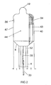
- Figures 1 to 3 show a designed for operation on mains voltage halogen incandescent lamp 1. In principle, however, the invention is also applicable to NV or MV halogen incandescent lamps.
- the halogen incandescent lamp 1 has, according to FIGS. 1 and 2, a lamp vessel 2 which is preferably made of quartz glass and on whose lower end section in FIG. 1 a base 4 is formed by a pinch seal which can be inserted into a socket (not shown). This base 4 is via a circumferential chamfer 6 in a piston 8 of the lamp vessel 2 via.
- the end portion of the lamp vessel 2 remote from the base 4 is formed by a dome 10 on which a pump stem extension 12 is formed.
- a luminous body 14 is arranged, which is executed in the described embodiment with two spiral arms 16, 18, which are connected to each other via a connecting part 20.
- the helical arms 16, 18 are inclined, so that their distance downwards, towards the base 4, increases.
- the two spiral arms 16, 18 go into power supply lines 22, 24, whose end portions are immersed in the base 4 formed by the pinch seal and are each connected to a molybdenum foil 26, 28, which are also embedded in the base 4. These are in turn connected to approximately U-shaped outer power supply, hereinafter referred to as contacts 30, 32, whose bent end portions are immersed in channels of the base 4 or embedded in these.
- the spiral arms 16, 18, the connecting part 20 and the two power supply lines 22, 24 are preferably made of tungsten.
- the holding nubs 34, 36 are each formed with an approximately elliptical cross section, the longitudinal axis of the horizontally arranged in Figure 1 region 38 of the connecting part 20 covers a maximum connection area between the elliptical end faces of the holding nubs 34, 36 and the connecting part 20th to achieve.
- a pumping tube is attached to the exhaust nozzle extension 12, through which the interior of the piston 8 is evacuated and filled with a halogen-containing filling gas. After filling, the pump tube is removed and the pump stem attachment 12 is sealed.
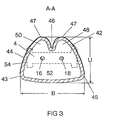
- the piston 8 is not designed with a cylindrical cross-section, as in the prior art described above, but has a view towards the observer in the illustration according to FIG facing light exit window 40, to which a backward, ie from the light exit window 40 wegölbender vessel portion 42 connects.
- the light exit window 40 passes over two rounded surface portions 43, 45 in the vaulted back to the vessel portion 42.
- a light-reflecting layer 44 for example, designed as a dichroic or silver or aluminum layer can be.
- the coating is indicated in Figure 2 by a shading.
- the light emission window 40 is not covered by this reflective layer 44.
- the wall regions of the vessel section 42 adjoining the light exit window 40 are curved approximately parabolically or ellipsoidally, wherein a constriction 46 is formed in the apex, through which the wall bulges approximately kidney-shaped back toward the light exit window 40.
- two curved reflection regions 48, 50 are formed, which are each associated with one of the helical arms 16, 18 and engage around these in sections at a distance.
- a partial reflector is formed by the reflection regions 48, 50, by which the light radiated by the associated helix arm 16, 18 is reflected in the direction of the exit window 40, so that the emission angle of the halogen lamp 1 is substantially sharper than with conventional lamps is and thus a uniform illumination of a predetermined area is made possible.
- the constriction 46 extends rearwardly practically over the entire height of the vessel portion 42 up to the chamfer 6, correspondingly, the two reflection regions 48, 50 extend over a range which is higher than the length of the two helical arms 16, 18.
- the lowest point of the constriction 46 seen in cross-section lies in a plane of symmetry between the two helical arms 16, 18, which runs perpendicular to the plane of the drawing in FIG.
- the width B of the exit window is greater than the depth U, ie, greater than the maximum distance between the light exit window 40 and the inwardly curved rear wall or the two apexes 47 of the vessel section 42.
- the cross-sectional shape of the piston 8 of the illustrated embodiment is also characterized in that in the view of Figure 3 the mean radius of curvature of the light exit window 40 is greater than that of the vessel portion 42 bulging toward the rear.
- the base 4 is slightly offset to the left, towards the constriction 46, so that the distance T to the apex of the exit window 40 is greater than the distance t to the two in the representation of Figure 2 perpendicular to the plane arranged by the constriction 46 (only visible in FIG. 3) of the vessel section 42.
- the pumping lug extension 12 is arranged as an extension of the vertical axis of the base 4 and thus likewise offset toward the apex 47 of the two kidney-shaped reflection regions 48, 50.
- the middle region 52 in FIG. 1 is slightly recessed on both sides (perpendicular to the plane of the drawing in FIG. 1), so that two webs 54 remain at the edge of the base 4.
- the coating preferably extends as far as the two surface sections 43, 45 and also covers the dome 10 and at least part of the chamfer 6, wherein preferably also that region of the chamfer 6 is coated, which is arranged below the light exit window 40 (FIG. 1) ,
Landscapes
- Non-Portable Lighting Devices Or Systems Thereof (AREA)
- Vessels And Coating Films For Discharge Lamps (AREA)
Abstract
Description
Die Erfindung betrifft eine Halogenglühlampe gemäß dem Oberbegriff des Patentanspruches 1.The invention relates to a halogen incandescent lamp according to the preamble of claim 1.
Eine derartige Seitenreflektorlampe wird auf der Internetdomain www.osram.de unter der Produktbezeichnung "MINISTAR®" beschrieben. Bei dieser Halogenglühlampe ist ein Umfangsabschnitt eines Lampengefäßes mit einer reflektierenden Beschichtung versehen, so dass am Lampengefäß ein seitlich angeordnetes Lichtaustrittsfenster verbleibt, das es ermöglicht, diese Lampe beispielsweise als Downlight zu verwenden, wobei die Lampe in Horizontalrichtung montiert wird. Derartige Reflektorlampen sind äußerst kompakt aufgebaut und benötigen daher bei der Montage einen minimalen Einbauraum.Such a side reflector lamp is described on the Internet domain www.osram.de under the product name "MINISTAR®". In this halogen incandescent lamp, a peripheral portion of a lamp vessel is provided with a reflective coating so that a laterally arranged light emission window remains on the lamp vessel, which makes it possible, for example, to use this lamp as a downlight, the lamp being mounted in the horizontal direction. Such reflector lamps are constructed extremely compact and therefore require a minimum installation space during installation.
Diese bekannte Konstruktion ist wesentlich einfacher aufgebaut als herkömmliche Reflektorlampen, wie sie beispielsweise in der europäischen Patentschrift EP 0 495 194 B1 beschrieben sind. Derartige Reflektorlampen bestehen aus einem Reflektor, der von einer parabolischen oder ellipsoidförmigen Glaskalotte gebildet wird und einer Halogenglühlampe, die in der optischen Achse des Reflektors befestigt ist.This known construction is constructed much simpler than conventional reflector lamps, as described for example in the European patent EP 0 495 194 B1. Such reflector lamps consist of a reflector which is formed by a parabolic or ellipsoidal glass dome and a halogen incandescent lamp which is fixed in the optical axis of the reflector.
Es zeigte sich, dass die kompakten Halogenglühlampen mit einem im Lampengefäß integrierten Reflektor insbesondere dann, wenn ein im Lampengefäß aufgenommener Leuchtkörper mit zumindest zwei Wendelabschnitten ausgebildet ist, hinsichtlich des ausgestrahlten Lichtstroms verbesserungsfähig ist. Leuchtkörper mit zwei Wendelabschnitten werden beispielsweise bei zum Betrieb an Netzspannung vorgesehenen Halogenglühlampen eingesetzt, wie sie in der europäischen Patentschrift EP 0 446 460 B1 beschrieben sind.It has been found that the compact halogen incandescent lamps with a reflector integrated in the lamp vessel can be improved with regard to the emitted luminous flux, in particular when a luminous body accommodated in the lamp vessel is formed with at least two filament sections. Illuminants with two filament sections are used, for example, in the case of halogen incandescent lamps intended for operation on mains voltage, as described in European Patent EP 0 446 460 B1.
Der Erfindung liegt die Aufgabe zugrunde, eine Halogenglühlampe mit Seitenreflektor zu schaffen, bei der die Ausleuchtung einer vorbestimmten Fläche verbessert ist.The invention has for its object to provide a halogen incandescent lamp with side reflector, in which the illumination of a predetermined area is improved.
Diese Aufgabe wird erfindungsgemäß durch die Merkmale des Patentanspruches 1 gelöst. Besonders vorteilhafte Ausführungen der Erfindung sind in den abhängigen Ansprüchen beschrieben.This object is achieved by the features of claim 1. Particularly advantageous embodiments of the invention are described in the dependent claims.
Die erfindungsgemäße Halogenglühlampe hat ein einseitig abgedichtetes Lampengefäß, in dem zumindest ein Leuchtkörper aufgenommen ist, wobei ein Abschnitt des Lampengefäßes als Seitenreflektor ausgeführt ist, der sich nur über einen Teilbereich des Lampengefäßumfangs erstreckt, so dass ein Lichtaustrittsfenster verbleibt. Erfindungsgemäß wölbt sich im Querschnitt gesehen der als Reflektor wirkende Gefäßabschnitt von dem vergleichsweise flach gekrümmten oder eben ausgeführten Lichtaustrittsfenster weg. Der mittlere Krümmungsradius des Lichtaustrittsfensters ist dabei größer als der mittlere Krümmungsradius des sich nach hinten auswölbenden, als Reflektor wirkenden Gefäßabschnittes ausgeführt. D.h. das üblicher Weise zylindrisch ausgeführte Lampengefäß erhält im Bereich des Reflektors eine Krümmung, die beispielsweise etwa parabolisch oder ellipsoid ausgeführt ist und somit hinsichtlich der Reflektionseigenschaften optimiert ist, so dass der aus dem Lichtaustrittsfenster austretende Lichtstrom gegenüber herkömmlichen Lösungen vergrößert und eine gezielte Ausleuchtung eines vorbestimmten Bereiches ermöglicht ist.The halogen incandescent lamp according to the invention has a lamp vessel sealed on one side, in which at least one luminous element is accommodated, wherein a section of the lamp vessel is designed as a side reflector, which extends only over a partial area of the lamp vessel periphery, so that a light exit window remains. According to the invention, the vessel section acting as a reflector bulges away from the comparatively flat or flat light exit window, viewed in cross-section. The mean radius of curvature of the light exit window is greater than the average radius of curvature of the vaulting towards the rear, acting as a reflector vessel section executed. That is, the usual manner cylindrically executed lamp vessel receives in the region of the reflector a curvature, which is performed for example approximately parabolic or ellipsoidal and thus optimized in terms of reflection properties, so that emerging from the light exit window luminous flux over conventional solutions increases and a targeted illumination of a predetermined range is possible.
Vorzugsweise ist die im Querschnitt gesehene Breite des Lichtaustrittsfensters größer als die Tiefe des als Reflektor ausgeführten Gefäßabschnitts.Preferably, the width seen in the cross section of the light exit window is greater than the depth of the designed as a reflector vessel portion.
Die Erfindung kann besonders vorteilhaft bei einer Halogenglühlampe angewendet werden, bei der der Leuchtkörper mit zwei Wendelarmen ausgeführt ist. In diesem Fall wird in einem Scheitel der Auswölbung des reflektierenden Gefäßabschnittes eine sich in Richtung zum Lichtaustrittsfenster erstreckende Einschnürung ausgebildet, so dass eine Rückwandung des Gefäßabschnittes nierenförmig eingezogen ist. Mit anderen Worten, der als Reflektor ausgebildete Lampenkolben wird mit zwei Einmuldungen versehen, deren Geometrie so ausgelegt ist, dass die von jedem Wendelarm abgegebene Lichtstrahlung in optimaler Weise reflektiert wird.The invention can be applied particularly advantageously in a halogen incandescent lamp, in which the luminous element is designed with two spiral arms. In this case, a constriction extending in the direction of the light exit window is formed in a vertex of the bulge of the reflective vessel section, so that a rear wall of the vessel section is retracted kidney-shaped. In other words, the lamp bulb formed as a reflector is provided with two Einmuldungen whose geometry is designed so that the output of each helical arm light radiation is reflected in an optimal manner.
Bei dieser Lösung wird es besonders bevorzugt, wenn diese Einschnürung in einer Symmetrieebene zu den Wendelarmen angeordnet ist.In this solution, it is particularly preferred if this constriction is arranged in a plane of symmetry to the helical arms.
Die Fixierung der Leuchtkörper erfolgt insbesondere bei für Netzspannung vorgesehenen Halogenglühlampen mit Haltenoppen, wie sie in der eingangs genannten europäischen Patentschrift EP 0 446 460 B1 beschrieben sind. Derartige Haltenoppen sind im Prinzip Einwölbungen des Lampengehäuses, zwischen denen ein Teilbereich des Leuchtkörpers eingeklemmt ist. Bei der erfindungsgemäßen Lösung ist vorzugsweise eine Haltenoppe im Bereich des Abstrahlfensters und eine diametral dazu angeordnete Haltenoppe im Bereich der rückwärtigen Einschnürung ausgebildet.The fixation of the luminous element is carried out in particular at mains voltage provided halogen incandescent lamps with Halteoppen, as described in the aforementioned European Patent EP 0 446 460 B1. Such holding nubs are in principle bulges of the lamp housing, between which a portion of the filament is clamped. In the solution according to the invention, a holding nub is preferably formed in the region of the emission window and a retaining nub arranged diametrically therewith in the region of the rear constriction.
Vorteilhafter Weise wird der Leuchtkörper mit zwei vorzugsweise schräg angestellten Wendelarmen ausgeführt, die über ein Verbindungsteil miteinander verbunden sind, an dem die Haltenoppen angreifen.Advantageously, the filament is carried out with two preferably inclined spiral arms, which are connected to each other via a connecting part on which attack the holding nubs.
Bei einem bevorzugten Ausführungsbeispiel ist der reflektierende Gefäßabschnitt mit einer Beschichtung versehen, die vorzugsweise auf dem Außenumfang des Lampengefäßes aufgebracht ist.In a preferred embodiment, the reflective vessel portion is provided with a coating which is preferably applied to the outer periphery of the lamp vessel.
Das abgedichtete Ende des Lampengefäßes wird vorteilhafter Weise als Sockel ausgebildet, wie er beispielsweise in der europäischen Patentschrift EP 0 897 604 B1 beschrieben ist.The sealed end of the lamp vessel is advantageously formed as a base, as described for example in European Patent EP 0 897 604 B1.
Das. Lampengefäß geht bei einem erfindungsgemäßen Ausführungsbeispiel über eine umlaufende Fase in diesen Sockel über.The. Lamp vessel is in an embodiment of the invention via a circumferential chamfer in this base over.
Der Sockel ist vorzugsweise näher zum Scheitel des reflektierenden Gefäßabschnitts als zum Scheitel des Lichtaustrittsfensters angeordnet.The base is preferably arranged closer to the vertex of the reflective vessel section than to the vertex of the light exit window.
Ein Pumpstängelansatz zum Befüllen der Halogenglühlampe kann an einer den reflektierenden Gefäßabschnitt überdeckenden Kuppe angeordnet sein.A pump stalk attachment for filling the halogen incandescent lamp can be arranged on a dome covering the reflective vessel section.
Erfindungsgemäß wird es bevorzugt, wenn die Halogenglühlampe für den Betrieb an Netzspannung ausgelegt ist.According to the invention it is preferred if the halogen incandescent lamp is designed for operation on mains voltage.
Nachstehend wird die Erfindung anhand eines bevorzugten Ausführungsbeispiels näher erläutert. Es zeigen:
- Figur 1
- eine Vorderansicht einer erfindungsgemäßen Halogenglühlampe;
Figur 2- eine Seitenansicht der Halogenglühlampe aus Figur 1 und
- Figur 3
- einen Schnitt entlang der Linie A-A in Figur 1.
- FIG. 1
- a front view of a halogen incandescent lamp according to the invention;
- FIG. 2
- a side view of the halogen incandescent lamp of Figure 1 and
- FIG. 3
- a section along the line AA in Figure 1.
Die Figuren 1 bis 3 zeigen eine für den Betrieb an Netzspannung ausgelegte Halogenglühlampe 1. Prinzipiell ist die Erfindung jedoch auch bei NV- oder MV-Halogenglühlampen einsetzbar.Figures 1 to 3 show a designed for operation on mains voltage halogen incandescent lamp 1. In principle, however, the invention is also applicable to NV or MV halogen incandescent lamps.
Die Halogenglühlampe 1 hat gemäß den Figuren 1 und 2 ein vorzugsweise aus Quarzglas bestehendes Lampengefäß 2, an dessen in Figur 1 unterem Endabschnitt durch eine Quetschdichtung ein Sockel 4 ausgebildet ist, der in eine nicht dargestellte Fassung eingesetzt werden kann. Dieser Sockel 4 geht über eine umlaufende Fase 6 in einen Kolben 8 des Lampengefäßes 2 über. Der vom Sockel 4 entfernte Endabschnitt des Lampengefäßes 2 ist durch eine Kuppe 10 gebildet, an der ein Pumpstängelansatz 12 ausgebildet ist.The halogen incandescent lamp 1 has, according to FIGS. 1 and 2, a
Im Lampengefäß 2 ist ein Leuchtkörper 14 angeordnet, der bei dem beschriebenen Ausführungsbeispiel mit zwei Wendelarmen 16, 18 ausgeführt ist, die über ein Verbindungsteil 20 miteinander verbunden sind. Wie Figur 1 entnehmbar ist, sind die Wendelarme 16, 18 schräg angestellt, so dass sich deren Abstand nach unten, zum Sockel 4 hin vergrößert. Die beiden Wendelarme 16, 18 gehen in Stromzuführungen 22, 24 über, deren Endabschnitte in den durch die Quetschdichtung gebildeten Sockel 4 eintauchen und mit jeweils einer Molybdänfolie 26, 28 verbunden sind, die ebenfalls in den Sockel 4 eingebettet sind. Diese sind wiederum mit etwa U-förmig ausgebildeten äußeren Stromzuführungen, im Folgenden Kontakte 30, 32 genannt verbunden, deren zurückgebogene Endabschnitte in Kanäle des Sockels 4 eintauchen oder in diesen eingebettet sind. Die Wendelarme 16, 18, das Verbindungsteil 20 und die beiden Stromzuführungen 22, 24 sind vorzugsweise aus Wolfram hergestellt.In the
Die beiden in den Sockel 4 eingebetteten Stromzuführungen 22, 24 sind nicht stabil genug, um die beiden Wendelarme 16, 18 in ihrer vorbestimmten Relativposition innerhalb des Kolbens 8 zu positionieren. Daher sind am Lampengefäß 2 etwa in Höhe des Zwischenteils 20 Haltenoppen 34, 36 ausgebildet, die sich in der Darstellung gemäß Figur 1 senkrecht zur Zeichenebene und in der Darstellung gemäß Figur 2 parallel zur Zeichenebene erstrecken. Diese diametral zueinander liegenden Haltenoppen 34, 36 sind durch nach innen, zum Zwischenteil 20 hin verformte Wandungsbereiche des Kolbens 8 ausgebildet, d.h. dessen Wandung ist im Bereich dieser Haltenoppen 34, 36 nach innen hin verformt, so dass das Verbindungsteil 20 zwischen den beiden Stirnflächen der Haltenoppen 34, 36 eingeklemmt und somit die Wendelarme 16, 18 lagefixiert sind. Diese Noppentechnologie ist ausführlich in der eingangs genannten EP 0 446 460 B1 erläutert. Bei dem dargestellten Ausführungsbeispiel sind die Haltenoppen 34, 36 jeweils mit einem etwa elliptischen Querschnitt ausgebildet, dessen Längsachse den in Figur 1 horizontal angeordneten Bereich 38 des Verbindungsteils 20 überdeckt, um eine maximale Verbindungsfläche zwischen den elliptischen Stirnseiten der Haltenoppen 34, 36 und dem Verbindungsteil 20 zu erzielen.The two embedded in the
Bei der Fertigung wird an den Pumpstängelansatz 12 ein Pumprohr angesetzt, durch das das Innere des Kolbens 8 evakuiert und mit einem Halogene enthaltenden Füllgas gefüllt wird. Nach dem Befüllen wird das Pumprohr entfernt und der Pumpstängelansatz 12 zugeschmolzen.During production, a pumping tube is attached to the
Wie insbesondere aus dem in Figur 3 dargestellten Schnitt entlang der Linie A-A in Figur 1 hervorgeht, ist der Kolben 8 nicht - wie beim eingangs beschriebenen Stand der Technik - mit einem zylinderförmigen Querschnitt ausgeführt, sondern hat ein in der Darstellung gemäß Figur 1 zum Betrachter hin weisendes Lichtaustrittsfenster 40, an das sich ein nach hinten, d.h. vom Lichtaustrittsfenster 40 weg auswölbender Gefäßabschnitt 42 anschließt. Das Lichtaustrittsfenster 40 geht dabei über zwei abgerundete Flächenabschnitte 43, 45 in den nach hinten ausgewölbten Gefäßabschnitt 42 über. Auf der Außenumfangsfläche des Gefäßabschnittes 42 ist - wie in Figur 3 gestrichelt angedeutet - eine lichtreflektierende Schicht 44 aufgebracht, die beispielsweise als dichroitische oder als Silber- oder Aluminiumschicht ausgeführt sein kann. Die Beschichtung ist in Figur 2 durch eine Schattierung angedeutet. Das Lichtaustrittsfenster 40 ist nicht von dieser reflektierenden Schicht 44 bedeckt.As can be seen, in particular, from the section along the line AA in FIG. 1, shown in FIG. 3, the
Gemäß Figur 3 sind die sich an das Lichtaustrittsfenster 40 anschließenden Wandungsbereiche des Gefäßabschnittes 42 etwa parabolisch oder ellipsoid gekrümmt, wobei im Scheitel eine Einschnürung 46 ausgebildet ist, durch die sich die Wandung etwa nierenförmig wieder zurück hin zum Lichtaustrittsfenster 40 einwölbt.According to FIG. 3, the wall regions of the
Durch diese Einschnürung 46 werden zwei gekrümmte Reflektionsbereiche 48, 50 gebildet, die jeweils einem der Wendelarme 16, 18 zugeordnet sind und diese abschnittsweise im Abstand umgreifen. Durch die Reflektionsbereiche 48, 50 wird jeweils ein Teilreflektor ausgebildet, durch den das vom zugeordneten Wendelarm 16, 18 abgestrahlte Licht in Richtung zum Austrittsfenster 40 reflektiert wird, so dass der Ausstrahlwinkel der Halogenlampe 1 wesentlich schärfer begrenzt ist, als dies bei herkömmlichen Lampen der Fall ist und somit eine gleichmäßige Ausleuchtung einer vorbestimmten Fläche ermöglicht wird.By this
Die Einschnürung 46 erstreckt sich rückseitig praktisch über die gesamte Höhe des Gefäßabschnittes 42 bis hin zur Fase 6, entsprechend erstrecken sich auch die beiden Reflektionsbereiche 48, 50 über einen Bereich, der höher als die Länge der beiden Wendelarme 16, 18 ist.The
Der im Querschnitt gesehen tiefste Punkt der Einschnürung 46 liegt in einer Symmetrieebene zwischen den beiden Wendelarmen 16, 18, die in Figur 3 senkrecht zur Zeichenebene verläuft. Wie in Figur 3 dargestellt, ist die Breite B des Austrittsfensters größer als die Tiefe U, d.h. größer als der maximale Abstand zwischen dem Lichtaustrittsfenster 40 und der einwärts gekrümmten Rückwandung oder den beiden Scheiteln 47 des Gefäßabschnitts 42 ausgebildet. Die Querschnittsform des Kolbens 8 des dargestellten Ausführungsbeispiels ist auch dadurch gekennzeichnet, dass in der Ansicht nach Figur 3 der mittlere Krümmungsradius des Lichtaustrittsfensters 40 größer ist als derjenige des sich nach hinten auswölbenden Gefäßabschnittes 42.The lowest point of the
Gemäß Figur 2 ist der Sockel 4 etwas nach links, hin zur Einschnürung 46 versetzt, so dass der Abstand T zum Scheitel des Austrittsfensters 40 größer ist als der Abstand t zu den beiden in der Darstellung gemäß Figur 2 senkrecht zur Zeichenebene angeordneten, durch die Einschnürung 46 (nur in Figur 3 sichtbar) gebildeten Scheiteln 47 des Gefäßabschnitts 42. Wie insbesondere aus Figur 2 hervorgeht, ist der Pumpstängelansatz 12 in Verlängerung der Hochachse des Sockels 4 angeordnet und somit ebenfalls zum Scheitel 47 der beiden nierenförmigen Reflektionsbereiche 48, 50 hin versetzt. Bei dem dargestellten Sockeltyp ist der in Figur 1 mittlere Bereich 52 beidseitig etwas ausgenommen (senkrecht zur Zeichenebene in Fig. 1), so dass am Rand des Sockels 4 zwei Stege 54 stehen bleiben.According to Figure 2, the
Die Beschichtung erstreckt sich vorzugsweise bis zu den beiden Flächenabschnitte 43, 45 hin und überdeckt auch die Kuppe 10 sowie zumindest einen Teil der Fase 6, wobei vorzugsweise auch derjenige Bereich der Fase 6 beschichtet ist, der unterhalb des Lichtaustrittsfensters 40 (Figur 1) angeordnet ist.The coating preferably extends as far as the two
Claims (15)
Applications Claiming Priority (1)
| Application Number | Priority Date | Filing Date | Title |
|---|---|---|---|
| DE102004033117A DE102004033117A1 (en) | 2004-07-08 | 2004-07-08 | halogen bulb |
Publications (2)
| Publication Number | Publication Date |
|---|---|
| EP1632986A2 true EP1632986A2 (en) | 2006-03-08 |
| EP1632986A3 EP1632986A3 (en) | 2008-02-06 |
Family
ID=35511546
Family Applications (1)
| Application Number | Title | Priority Date | Filing Date |
|---|---|---|---|
| EP05012058A Withdrawn EP1632986A3 (en) | 2004-07-08 | 2005-06-03 | Halogen incandescent lamp |
Country Status (7)
| Country | Link |
|---|---|
| US (1) | US7397192B2 (en) |
| EP (1) | EP1632986A3 (en) |
| JP (1) | JP2006024566A (en) |
| CN (1) | CN1719577A (en) |
| CA (1) | CA2511707A1 (en) |
| DE (1) | DE102004033117A1 (en) |
| TW (1) | TWI303076B (en) |
Cited By (1)
| Publication number | Priority date | Publication date | Assignee | Title |
|---|---|---|---|---|
| EP1739725A3 (en) * | 2005-04-25 | 2011-02-23 | Patent-Treuhand-Gesellschaft für elektrische Glühlampen mbH | Halogen incandescent lamp and manufacturing method thereof |
Families Citing this family (7)
| Publication number | Priority date | Publication date | Assignee | Title |
|---|---|---|---|---|
| DE102005019829A1 (en) * | 2005-04-28 | 2006-11-02 | Patent-Treuhand-Gesellschaft für elektrische Glühlampen mbH | Reflector lamp with high voltage operation includes filament segments retained in a plane perpendicular with the lamp longitudinal axis by funnel-shaped pinches turned-in from the planar top |
| DE102005045644A1 (en) * | 2005-09-23 | 2007-03-29 | Patent-Treuhand-Gesellschaft für elektrische Glühlampen mbH | Electric lamp with holding nubs for the filament |
| WO2008050253A2 (en) * | 2006-10-24 | 2008-05-02 | Philips Intellectual Property & Standards Gmbh | Electric incandescent lamp with filament array and infrared reflective coating |
| DE102007035596A1 (en) * | 2007-07-30 | 2009-02-05 | Osram Gesellschaft mit beschränkter Haftung | Electric lamp with an outer bulb and a built-in lamp and a method for its production |
| DE102008032167A1 (en) * | 2008-07-08 | 2010-01-14 | Osram Gesellschaft mit beschränkter Haftung | halogen bulb |
| JP6269816B2 (en) | 2014-03-27 | 2018-01-31 | 日本電気株式会社 | POS terminal, information processing apparatus, white balance adjustment method and program |
| CN104616970A (en) * | 2015-01-06 | 2015-05-13 | 浙江新光阳照明股份有限公司 | Two-step filament hanging method in production of single-ended halogen tungsten lamp |
Citations (1)
| Publication number | Priority date | Publication date | Assignee | Title |
|---|---|---|---|---|
| US2135480A (en) * | 1936-08-26 | 1938-11-08 | Birdseye Electric Company | Reflecting glow lamp |
Family Cites Families (12)
| Publication number | Priority date | Publication date | Assignee | Title |
|---|---|---|---|---|
| NL6404941A (en) * | 1964-05-05 | 1965-11-08 | ||
| NL6505581A (en) * | 1965-04-30 | 1966-10-31 | ||
| NL7602483A (en) * | 1976-03-10 | 1977-09-13 | Philips Nv | MIRROR CONDENSOR LAMP. |
| NL7909231A (en) * | 1979-12-21 | 1981-07-16 | Philips Nv | LAMP / REFLEX UNIT. |
| US4988911A (en) * | 1988-10-17 | 1991-01-29 | Miller Jack V | Lamp with improved photometric distribution |
| DE4008367A1 (en) * | 1990-03-15 | 1991-09-26 | Patent Treuhand Ges Fuer Elektrische Gluehlampen Mbh | ONE-SIDED CRUSHED HALOGEN BULB |
| DE9017071U1 (en) * | 1990-12-18 | 1991-03-07 | Patent-Treuhand-Gesellschaft für elektrische Glühlampen mbH, 8000 München | Reflector lamp |
| DE19709928A1 (en) * | 1997-03-11 | 1998-09-17 | Patent Treuhand Ges Fuer Elektrische Gluehlampen Mbh | Halogen light bulb and socket |
| DE602004008479T2 (en) * | 2003-07-28 | 2008-05-21 | Koninklijke Philips Electronics N.V. | ELECTRIC LAMP |
| US20060170361A1 (en) * | 2005-01-31 | 2006-08-03 | Osram Sylvania Inc. | Single-ended Arc Discharge Vessel with a Divider Wall |
| DE102005019113A1 (en) * | 2005-04-25 | 2006-10-26 | Patent-Treuhand-Gesellschaft für elektrische Glühlampen mbH | Halogen incandescent lamp and method for its production |
| DE102005019829A1 (en) * | 2005-04-28 | 2006-11-02 | Patent-Treuhand-Gesellschaft für elektrische Glühlampen mbH | Reflector lamp with high voltage operation includes filament segments retained in a plane perpendicular with the lamp longitudinal axis by funnel-shaped pinches turned-in from the planar top |
-
2004
- 2004-07-08 DE DE102004033117A patent/DE102004033117A1/en not_active Withdrawn
-
2005
- 2005-06-03 EP EP05012058A patent/EP1632986A3/en not_active Withdrawn
- 2005-06-10 TW TW094119173A patent/TWI303076B/en not_active IP Right Cessation
- 2005-07-05 US US11/172,788 patent/US7397192B2/en not_active Expired - Fee Related
- 2005-07-06 CA CA002511707A patent/CA2511707A1/en not_active Abandoned
- 2005-07-07 JP JP2005198861A patent/JP2006024566A/en active Pending
- 2005-07-08 CN CN200510082560.7A patent/CN1719577A/en active Pending
Patent Citations (1)
| Publication number | Priority date | Publication date | Assignee | Title |
|---|---|---|---|---|
| US2135480A (en) * | 1936-08-26 | 1938-11-08 | Birdseye Electric Company | Reflecting glow lamp |
Cited By (1)
| Publication number | Priority date | Publication date | Assignee | Title |
|---|---|---|---|---|
| EP1739725A3 (en) * | 2005-04-25 | 2011-02-23 | Patent-Treuhand-Gesellschaft für elektrische Glühlampen mbH | Halogen incandescent lamp and manufacturing method thereof |
Also Published As
| Publication number | Publication date |
|---|---|
| CN1719577A (en) | 2006-01-11 |
| US20060006801A1 (en) | 2006-01-12 |
| DE102004033117A1 (en) | 2006-01-26 |
| JP2006024566A (en) | 2006-01-26 |
| TWI303076B (en) | 2008-11-11 |
| US7397192B2 (en) | 2008-07-08 |
| TW200603202A (en) | 2006-01-16 |
| EP1632986A3 (en) | 2008-02-06 |
| CA2511707A1 (en) | 2006-01-08 |
Similar Documents
| Publication | Publication Date | Title |
|---|---|---|
| DE69521371T2 (en) | ELECTRIC REFLECTOR LAMP | |
| DE19543006C5 (en) | Fixing a light source in a reflector of a spot lamp | |
| EP1632986A2 (en) | Halogen incandescent lamp | |
| DE3932140A1 (en) | VEHICLE HEADLIGHT | |
| EP1739725A2 (en) | Halogen incandescent lamp and manufacturing method thereof | |
| EP2320129B1 (en) | Reflector lamp | |
| DE20204104U1 (en) | Luminaire for installation in the cover cap of an exterior rear-view mirror for motor vehicles | |
| EP2812629B1 (en) | Reflector emitter | |
| DE102006034324A1 (en) | Reflector for motor vehicle, particularly vehicle headlights, has receiver for illuminant, where reflector has main body provided in sections with reflection prisms, and is designed symmetrically rotational, parabolic and elliptical | |
| EP2095399B1 (en) | Two-filament lamp | |
| EP1659617A1 (en) | Light source | |
| DE102010002650A1 (en) | Halogen bulb for vehicle headlights | |
| DE19833475C2 (en) | Reflector as part of a motor vehicle headlight | |
| EP1745501B1 (en) | Spiral-wound filament for an incandescent lamp and incandescent lamp | |
| DE10135728C2 (en) | Method for dimensioning the geometry of a reflector for a lamp and lamp with such a reflector | |
| EP1672276A2 (en) | PAR-Lamp assembly | |
| EP1255279B1 (en) | Halogen incandescent lamp | |
| DE10222129A1 (en) | Vehicle lamp with a lamp and a hollow or cup-shaped reflector | |
| DE102008022144A1 (en) | Incandescent lamp e.g. H7 lamp, for use in motor vehicle head lamp, has lamp container provided with infrared radiation reflecting coating that is arranged on region of cylindrical container section circularly enclosing glow filament | |
| AT400886B (en) | LAMP | |
| DE102007048387A1 (en) | H4 lamp for use as headlight in motor vehicle, has dimmer cap formed in cross section in form of circle segment, where filament is arranged outside center of circle, and dimmer cap is implemented with elliptical cross section | |
| DE3149297A1 (en) | "SIGNAL LIGHT" | |
| WO2005098907A1 (en) | Reflector lamp with halogen filling | |
| WO2004095506A2 (en) | Halogen incandescent lamp | |
| DE10040501B4 (en) | Round light, grid for round light and slat for round light |
Legal Events
| Date | Code | Title | Description |
|---|---|---|---|
| PUAI | Public reference made under article 153(3) epc to a published international application that has entered the european phase |
Free format text: ORIGINAL CODE: 0009012 |
|
| AK | Designated contracting states |
Kind code of ref document: A2 Designated state(s): AT BE BG CH CY CZ DE DK EE ES FI FR GB GR HU IE IS IT LI LT LU MC NL PL PT RO SE SI SK TR |
|
| AX | Request for extension of the european patent |
Extension state: AL BA HR LV MK YU |
|
| PUAL | Search report despatched |
Free format text: ORIGINAL CODE: 0009013 |
|
| AK | Designated contracting states |
Kind code of ref document: A3 Designated state(s): AT BE BG CH CY CZ DE DK EE ES FI FR GB GR HU IE IS IT LI LT LU MC NL PL PT RO SE SI SK TR |
|
| AX | Request for extension of the european patent |
Extension state: AL BA HR LV MK YU |
|
| 17P | Request for examination filed |
Effective date: 20080220 |
|
| AKX | Designation fees paid |
Designated state(s): AT BE BG CH CY CZ DE DK EE ES FI FR GB GR HU IE IS IT LI LT LU MC NL PL PT RO SE SI SK TR |
|
| 17Q | First examination report despatched |
Effective date: 20100315 |
|
| STAA | Information on the status of an ep patent application or granted ep patent |
Free format text: STATUS: THE APPLICATION IS DEEMED TO BE WITHDRAWN |
|
| 18D | Application deemed to be withdrawn |
Effective date: 20100727 |