EP1631752B1 - Kraftfahrzeugbauteil zum dämpfen von stössen durch plastische verformung - Google Patents
Kraftfahrzeugbauteil zum dämpfen von stössen durch plastische verformung Download PDFInfo
- Publication number
- EP1631752B1 EP1631752B1 EP04742802A EP04742802A EP1631752B1 EP 1631752 B1 EP1631752 B1 EP 1631752B1 EP 04742802 A EP04742802 A EP 04742802A EP 04742802 A EP04742802 A EP 04742802A EP 1631752 B1 EP1631752 B1 EP 1631752B1
- Authority
- EP
- European Patent Office
- Prior art keywords
- figures
- alterations
- deformation
- effort
- bunching
- Prior art date
- Legal status (The legal status is an assumption and is not a legal conclusion. Google has not performed a legal analysis and makes no representation as to the accuracy of the status listed.)
- Expired - Lifetime
Links
- 230000035939 shock Effects 0.000 title description 17
- 239000004033 plastic Substances 0.000 title description 4
- 229920003023 plastic Polymers 0.000 title description 4
- 230000004075 alteration Effects 0.000 claims description 75
- 238000010521 absorption reaction Methods 0.000 claims description 9
- 238000005452 bending Methods 0.000 claims description 4
- 230000006835 compression Effects 0.000 claims description 4
- 238000007906 compression Methods 0.000 claims description 4
- 230000006378 damage Effects 0.000 claims description 3
- 230000000977 initiatory effect Effects 0.000 claims description 2
- 239000006096 absorbing agent Substances 0.000 description 8
- 239000000463 material Substances 0.000 description 8
- 230000015572 biosynthetic process Effects 0.000 description 7
- 230000000694 effects Effects 0.000 description 6
- 240000008042 Zea mays Species 0.000 description 4
- 230000000295 complement effect Effects 0.000 description 4
- 230000001186 cumulative effect Effects 0.000 description 4
- 239000013598 vector Substances 0.000 description 4
- 230000007423 decrease Effects 0.000 description 3
- 230000001965 increasing effect Effects 0.000 description 3
- 229910052751 metal Inorganic materials 0.000 description 3
- 239000002184 metal Substances 0.000 description 3
- 210000004417 patella Anatomy 0.000 description 3
- 238000012360 testing method Methods 0.000 description 3
- 229910000831 Steel Inorganic materials 0.000 description 2
- 238000012512 characterization method Methods 0.000 description 2
- 230000033001 locomotion Effects 0.000 description 2
- 230000002035 prolonged effect Effects 0.000 description 2
- 239000010959 steel Substances 0.000 description 2
- OKTJSMMVPCPJKN-UHFFFAOYSA-N Carbon Chemical compound [C] OKTJSMMVPCPJKN-UHFFFAOYSA-N 0.000 description 1
- 208000029152 Small face Diseases 0.000 description 1
- 208000027418 Wounds and injury Diseases 0.000 description 1
- 229910052782 aluminium Inorganic materials 0.000 description 1
- XAGFODPZIPBFFR-UHFFFAOYSA-N aluminium Chemical compound [Al] XAGFODPZIPBFFR-UHFFFAOYSA-N 0.000 description 1
- 238000013459 approach Methods 0.000 description 1
- 238000010009 beating Methods 0.000 description 1
- 229910052799 carbon Inorganic materials 0.000 description 1
- 239000002131 composite material Substances 0.000 description 1
- 230000001143 conditioned effect Effects 0.000 description 1
- 239000000470 constituent Substances 0.000 description 1
- 238000010276 construction Methods 0.000 description 1
- 230000008878 coupling Effects 0.000 description 1
- 238000010168 coupling process Methods 0.000 description 1
- 238000005859 coupling reaction Methods 0.000 description 1
- 230000001419 dependent effect Effects 0.000 description 1
- 230000006866 deterioration Effects 0.000 description 1
- 230000009977 dual effect Effects 0.000 description 1
- 229940082150 encore Drugs 0.000 description 1
- 238000011049 filling Methods 0.000 description 1
- 230000009975 flexible effect Effects 0.000 description 1
- 239000006260 foam Substances 0.000 description 1
- 239000003365 glass fiber Substances 0.000 description 1
- 208000014674 injury Diseases 0.000 description 1
- 230000000670 limiting effect Effects 0.000 description 1
- 238000005259 measurement Methods 0.000 description 1
- 239000007769 metal material Substances 0.000 description 1
- 238000000034 method Methods 0.000 description 1
- 210000000056 organ Anatomy 0.000 description 1
- 230000002093 peripheral effect Effects 0.000 description 1
- 230000000750 progressive effect Effects 0.000 description 1
- 230000001902 propagating effect Effects 0.000 description 1
- 238000011084 recovery Methods 0.000 description 1
- 238000007493 shaping process Methods 0.000 description 1
- 125000006850 spacer group Chemical group 0.000 description 1
- 230000004083 survival effect Effects 0.000 description 1
- 239000000725 suspension Substances 0.000 description 1
- 230000007704 transition Effects 0.000 description 1
- 238000003466 welding Methods 0.000 description 1
Images


Classifications
-
- F—MECHANICAL ENGINEERING; LIGHTING; HEATING; WEAPONS; BLASTING
- F16—ENGINEERING ELEMENTS AND UNITS; GENERAL MEASURES FOR PRODUCING AND MAINTAINING EFFECTIVE FUNCTIONING OF MACHINES OR INSTALLATIONS; THERMAL INSULATION IN GENERAL
- F16F—SPRINGS; SHOCK-ABSORBERS; MEANS FOR DAMPING VIBRATION
- F16F7/00—Vibration-dampers; Shock-absorbers
- F16F7/12—Vibration-dampers; Shock-absorbers using plastic deformation of members
-
- B—PERFORMING OPERATIONS; TRANSPORTING
- B62—LAND VEHICLES FOR TRAVELLING OTHERWISE THAN ON RAILS
- B62D—MOTOR VEHICLES; TRAILERS
- B62D21/00—Understructures, i.e. chassis frame on which a vehicle body may be mounted
- B62D21/15—Understructures, i.e. chassis frame on which a vehicle body may be mounted having impact absorbing means, e.g. a frame designed to permanently or temporarily change shape or dimension upon impact with another body
- B62D21/152—Front or rear frames
Definitions
- the invention relates in particular to the safety of vehicles, in particular in case of shocks, whether for example with a pedestrian, a cyclist, a motorcyclist, another motor vehicle, a fixed obstacle such as a construction such as a wall, dwelling, a tree, these few examples not constituting a limiting list of fixed or mobile obstacles with which a vehicle may collide.
- the Applicant has therefore sought to develop parts that better meet these conditions.
- the invention constitutes an important advance in this direction.
- the invention is directed to a mechanical device, comprising an elongated structural element, intended to at least partially collect certain shocks by deformation.
- This element comprises a tube of selected cross section.
- This tube is provided with localized alterations, shapes and respective positions chosen to satisfy substantially a given deformation law under joint compressive stress in the axis of the workpiece, and axis torque perpendicular to a plane passing through this axis.
- the law may comprise an energy absorption phase by bundling, followed by an erasure of the piece by swiveling, from at least one alteration zone having a dual function of bundling and swiveling and allowing initiate the swiveling.
- the cradle or the front structure of a vehicle is equipped with one or two front elements called “prolonged" or more than two extensions.
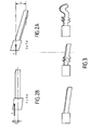
- FIG 1 which schematically illustrates an embodiment of the front part (left side) of a vehicle, in left view. It distinguishes a high and a low lane, marked substantially by the center line 10 (note that this high road is sometimes called the middle road, the high road is then located higher in the vehicle).
- the front of the vehicle is on the left of the figure.
- a part 11 called stretcher On the right, part of the body, at the center line 10, a part 11 called stretcher, which goes up to define the high way, ending with a shock absorber 14 and a high bumper beam rated 15 .
- a cradle 12 is mounted on the stretcher 11 in a flexible or rigid manner.
- This cradle 12 is continued by a so-called prolonged piece 20, followed by a low absorber (pedestrians) 24, then a low bumper beam marked 25.
- a front bumper 18 Between the beams 15 and 25 is defined a front bumper 18.
- a hanger 13 vertically connects the extension 20 and the part of the stretcher 11 which overhangs this extension. Note that the extension 20 is suspended from the stretcher 11 by means of the hinge 13. Here, this suspension is not a rigid connection.
- the Applicant has taken a different approach, by looking at structural elements such as the extensions mounted at the end of a short cradle, instead of the longest cradle most frequently used.
- shock absorbers are for example shock absorbers. These parts are produced in the form of closed bodies, hollow, made of sheet metal, having "bundling waves". It is about peripheral deformations in cross-section (the "waves"), or of angular breaks, or similar means, able to facilitate the folding of the piece on itself like a plastic bottle (bundling).
- the Applicant then first posed the problem of performing similar functions, but with long enough pieces, especially to serve as extensions, as defined above.
- the proposed members have a slenderness greater than 25, or even much greater than 25.
- E Young's modulus
- F the critical force of Euler
- the skilled person knows the other values that k takes in other cases.
- the profile may have the general shape of a straight cylindrical surface. Although its cross section can take many different polygonal shapes, it will most often be square or rectangular. However, the invention is also usable with a part having one or more cambering along its length.
- the bundling elements are made of sheet metal, in the form of U-profiles welded together to reconstitute a closed profile.
- the Applicant sought to obtain, by the same piece, first a longitudinal deformation ("bunching"), then a deformation with bending along a transverse axis ("swiveling").
- Couple refers both to the moment vector of a couple ( Figure 6A ) that the algebraic measurement of the torque, namely the amplitude of said vector.
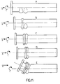
- the figure 3 illustrates very schematically the desired behavior, according to increasing efforts, from left to right.
- the Figure 4A shows a profiled piece of substantially uniform rectangular cross section.
- the Figure 4B shows the same room, with local alterations, seen in section, while the figure 4C is a left view of the room from the Figure 4B .
- the local alteration is in the form of a deformation, here by depression, of each of the two contiguous angles (1) and (2) of the section, while leaving the opposite face (f) deformed freely.
- the perimeter of the section is substantially preserved.
- the re-entrant alterations are on a small face, and the outgoing alterations (bosses) on a large face.
- the figure 5 shows an alteration of the same principle, but clearly dissymmetrical with respect to the median longitudinal plane P5 of the piece.
- the local alteration is in the form of a depression of the angle (1) and the face (f1), which is here the upper face, while leaving the adjacent face (f2) to deform freely.
- the perimeter of the section is substantially preserved.
- the figure 6 shows in perspective a piece thus provided with three alterations A1 to A3 according to the figure 5 .
- the alterations can be carried out by conventional forming (for example stamping), or by hydro-forming, or by using other similar shaping techniques.
- the Figure 6A gives position and solicitation parameters of a room for example according to the figure 6 , the front of the vehicle being on the left of the figure.
- the figures 7 illustrate the different steps (or sequences) of the deformation of a prolongation made in a hollow body, here a square tube, provided on two of its opposite faces symmetrical bulges made perpendicularly to the longitudinal axis and affecting the entire width of the faces concerned (outgoing folds or outgoing alterations) and on the other two opposite faces of symmetrical depressions also made perpendicular to the longitudinal axis and affecting the entire width of the faces concerned (incoming folds or re-entrant alterations).
- These alterations of the piece serve as deformation primers, when the piece is subjected to a force exerted along its axis.
- the Figure 7A represents the prolongation at rest.
- the Figures 8A and 8B are respectively an abacus which represents the evolution of the stress curve (y-axis) according to the time (x-axis) for a part subjected to a pure axial force according to the figures 7 , and an abacus representing the same phenomenon with in axis x the value of the crushing (or decrease of length) of the part during the shock.
- the forces in the room are the same on its upper and lower faces.
- the figures 9 relate to a piece identical to that of the Figure 7A . But they illustrate the case where this piece is subjected to forces that combine a force exerted along the longitudinal axis of the workpiece and a torque exerted along an axis perpendicular to the longitudinal axis of the workpiece and in a principal plane of symmetry of the workpiece. the piece (here of axis perpendicular to the plane of the figure). Taking the case of an off-axis force F, this results in a force in the axis A and a pair C.
- the Figures 10A and 10B are respectively an abacus representing the evolution of the stress curve (y-axis) according to the time (x-axis) for a part subjected simultaneously to a force and to a torque according to the figures 9 , and an abacus representing the same phenomenon with in axis x the value of the crushing (or decrease of length) of the part during the shock.
- the rotulage begins in an area close to the first effort peak. It is accompanied by the closure of the fold of the alteration on the upper face. We can consider that the rotulage is due to the fact that the peaks of effort in the two opposite faces of the part are neither of the same value, nor simultaneous.
- FIGS. 11A to 11E relate to an example of a part made according to the invention.
- This piece is provided on at least one of its faces, alterations that do not affect the totalized face concerned (in cross section). Such arrangements of parts are called here “unsymmetrical alterations” or “asymmetrical alterations”. This concept also encompasses the case where, according to another embodiment, the alterations are oriented, that is to say that they form a non-perpendicular angle with the longitudinal axis of the workpiece.
- the asymmetric alterations remain substantially contained in an area perpendicular to the axis of the part. It is possible to perform the alterations obliquely ("oriented"), with a chosen inclination. ( Figures 13 ).
- FIGS. 12A and 12B show that the bunching remains as long as one can maintain substantially simultaneous peaks of effort on the upper and lower faces. It's true on the figure 12A for the first two peaks, which correspond to the two alterations, successively. It is only then that one passes in rotulage, the folding part dissymmetrically, in principle elsewhere than on the alterations, as the figure 11E .
- Figures 12A and 12B include the two graphs representing the effort / time and effort / crush curves for parts according to the figures 11 .
- the figures 13 represent a part comprising, on the one hand, asymmetric alterations, whose function is to initiate bundling, and, on the other hand, one or more complementary alterations, which may be of different shape from the previous ones, and whose function is to initiate the rotulage. In addition, at least some of the alterations are oriented.
- the number of zones of alteration likely to cause bundling can be 1, 2 or 3, or more.
- the chosen point of swiveling it can be limited to a single zone of alteration, or take several, especially if several points of swiveling are desired.
- a type of asymmetric alteration can be both inbound and outbound, as shown by the Figures 14A and 14B , which are two views of the same room in two perpendicular axial planes.
- the straight sections of the two alterations are illustrated in S1 and S2.
- the alterations present reentrant folds, whereas on the Figure 14B the alterations are outgoing folds.
- the two planes of views can here treat two respective components of the couple.
- the alterations are deformed areas.
- one or more alterations may advantageously be emergent, that is to say that its top (outgoing alteration) or its bottom (re-entrant alteration) comprises an orifice (for example a light, or a bore), the shape and outlines will be chosen, for example according to the stress constraints to which the crash scenario leads.
- the part may also be at least partially internally provided with a lining, for example a slightly compressible foam. Selective filling can contribute to the definition of the bunching and / or swiveling points.
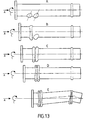
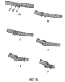
- the Figures 16 , 17 and 18 show different states of a part during its deformation, respectively in perspective, in top view, and in side view.
- the different phases of the figures correspond substantially.
- the part has alterations ⁇ 1, ⁇ 2, ⁇ 3 and ⁇ 4.
- the figure 16A shows that the alteration ⁇ 1 has two orifices, similar to those of the figure 15 .
- the alterations ⁇ 2, ⁇ 3 and ⁇ 4, here of the incoming asymmetric type, are clearly visible on the figure 18A .
- the Figures 16B , 17B and 18B show a beginning of bunching. This is accompanied by a limited recess of the left end of the piece, which puts it in the desired position so that the effort applied results in a bunching, here combined with a very light swiveling (zone d left end).
- the Figures 16C , 17C and 18C then, 16D, 17D and 18D, the previously initiated bunching continues, while the slight beating previously initiated remains substantially unchanged. Until then, it is therefore the bunching that predominates clearly. It absorbs a very significant amount of energy.
- An important aspect of the invention is that the erasure is preceded by a very important energy absorption phase, as we have seen.
- the invention makes it possible, for a prolongation of given length, to obtain the desired energy absorption law and then the erasure. Although this is essentially the low path of the front of the vehicle, it is not excluded to apply the proposed part to other elements of the front, or to other shocks, for example side or rear or even other applications than those of the automobile.
- the Applicant has also sought to obtain the desired effects using only holes or perforations ("holes"). This is what will now be described, based on 5 groups of figures constructed in the same way, and corresponding to 5 pieces with different arrangements of perforations. The first three pieces considered have holes placed asymmetrically (in the vicinity of a straight section); the last two pieces have against holes placed symmetrically in the vicinity of a cross section.
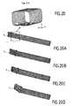
- the figure 19 illustrates, in a perspective view, the case of an alteration of the tube by two pairs of perforations placed on the lower edges or "edges" of the tube.
- the figure 20 repeat the figure 19 to facilitate understanding.
- a test has been defined to correspond substantially to the conditions of the test called "EURO NCAP" (European crash test), at an initial speed of 64km / h, reproducing the conditions of assembly of the part on a vehicle, but without its environment full.
- the part is subjected to a joint effort of compression and torque.
- the couple has the effect that the upper part of the tube (top in the figures) is more heavily stressed.
- Figures 19A and 20A are taken at a time close to the beginning of the deformation. Then, Figures 19B to 19D , as well as 20B to 20D, are taken at later times offset by 2.5, 5 and 10 milliseconds, respectively.
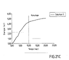
- the figure 21A shows the force measured as a function of time, in dashed line for the upper part of the tube, and in solid lines for its lower part, this effort passing through a section normal to the axis of the tube.
- time is counted in milliseconds.
- the effort F is counted in thousands of daN.
- the swiveling phenomenon starts when the curve "plunges" towards the 0 or negative values, ie after the 3rd peak.
- the vertical dashed line is a mark on the X-axis (at about 10 ms in time, or 120 mm in crush) and not the starting point of the swivel.
- the lower face passes in traction, which corresponds to a strong swiveling. More specifically, the resulting force on the lower face becomes a traction from the moment when the contribution in traction due to the torque becomes greater than the contribution due to the compressive force.
- the effort / crash curve of the figure 21B shows that the piece has much less resistance during the swiveling phase.
- the cumulative energy absorbed curve of the figure 21C shows that the absorbed energy peaks at around 4.5 kiloJoules when entering the swiveling phase, whereas before, it remains very close to linearity.
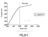
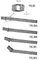
- This second piece has two pairs of similar perforations provided on two lateral faces of the tube, and a pair of perforations, homologous of the first in position, located on the underside of the tube.
- the cumulative energy absorbed curve of the figure 24C shows that the absorbed energy peaks at about 5 kiloJoules when it starts to swivel. Previously, it remains very close to linearity.
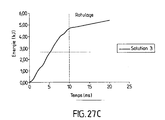
- This third piece has two perforations formed successively on the underside of the tube.
- the cumulative energy absorbed curve of the figure 27C shows that the absorbed energy peaks at about 5 kiloJoules when it starts to swivel, as for the second tube. Previously, it remains very close to linearity.
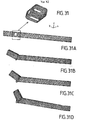
- This fourth piece has four perforations placed substantially at the same longitudinal level on the four edges or "edges" of the tube.
- the side views show that, under compression and torque, this tube bells, then patella.
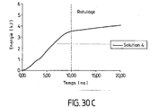
- the cumulative energy absorbed curve of the figure 30C shows that the energy absorbed caps much lower than previously, at about 3.5 kiloJoules.
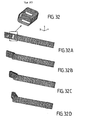
- This fifth piece has four perforations placed substantially at the same longitudinal level on the four faces of the tube. As before, this tube bottelle, then patella.
- the energy absorbed is even lower than before, since it caps at 2 kiloJoules, with a lack of linearity, and without any real transition between bunching and swabbing.
- asymmetrical perforations as described in the first three perforation tubes, will be preferred.
- the examples described are essentially illustrative, and it will be possible to combine the holes on edges and faces, keeping the asymmetrical character, at least partially, if desired. In particular, it is necessary to leave enough material to maintain the rigidity of the piece; this can be determined in a known manner.
- the number of perforations per section is dependent on the peak of effort allowed and the torque to be countered.
- the energy absorbed by the tube is conditioned by the dimensions of the tube and the alterations.
- the Applicant has also made comparisons between pieces having different geometries or shapes in cross section, with a substantially constant perimeter.
- the word “substantially” means in particular that the corners are rounded on optionally).
Landscapes
- Engineering & Computer Science (AREA)
- General Engineering & Computer Science (AREA)
- Mechanical Engineering (AREA)
- Chemical & Material Sciences (AREA)
- Combustion & Propulsion (AREA)
- Transportation (AREA)
- Vibration Dampers (AREA)
- Body Structure For Vehicles (AREA)
Claims (14)
- Mechanische Vorrichtung, die ein längliches Strukturelement aufweist, das dazu bestimmt ist, zumindest teilweise bestimmte Stöße durch Verformung aufzufangen,
dadurch gekennzeichnet, dass dieses Strukturelement oder Bauteil ein Profil mit einem gewählten Querschnitt aufweist,
wobei dieses Profil mit lokalisierten Veränderungen versehen ist, deren Formen bzw. Positionen gewählt werden, um im Wesentlichen ein gegebenes Gesetz der Verformung unter gemeinsamer Krafteinwirkung einer Kompression in der Achse des Bauteils und eines Achsdrehmoments lotrecht zu einer durch diese Achse verlaufenden Ebene zu erfüllen, wobei dieses Gesetz eine Phase der Energieabsorption durch Zusammenquetschen in Längsrichtung, gefolgt von einem Zurückweichen des Bauteils durch Schwenken in der Querachse, ausgehend von mindestens einer Zone von Veränderungen aufweist, die eine doppelte Funktion des Zusammenquetschens in Längsrichtung und des Schwenkens in der Querachse hat und es ermöglicht, das Schwenken in der Querachse einzuleiten. - Vorrichtung nach Anspruch 1, dadurch gekennzeichnet, dass zumindest manche der Veränderungen unsymmetrisch sind.
- Vorrichtung nach Anspruch 1, dadurch gekennzeichnet, dass zumindest manche der Veränderungen im Querschnitt nicht gleichmäßig sind.
- Vorrichtung nach einem der Ansprüche 1 bis 3, dadurch gekennzeichnet, dass zumindest manche der Veränderungen mit einem im Wesentlichen konstanten Umfang hergestellt werden.
- Vorrichtung nach einem der Ansprüche 1 bis 4, dadurch gekennzeichnet, dass mindestens eine der Veränderungen ausgerichtet ist.
- Vorrichtung nach einem der Ansprüche bis 5, dadurch gekennzeichnet, dass mindestens eine der Veränderungen eine oder mehrere Öffnungen aufweist.
- Vorrichtung nach einem der vorhergehenden Ansprüche, dadurch gekennzeichnet, dass zumindest manche der Veränderungen auf einer oder mehreren Kanten des Bauteils ausgebildet sind.
- Vorrichtung nach einem der vorhergehenden Ansprüche, dadurch gekennzeichnet, dass zumindest manche der Veränderungen auf einer oder mehreren Seiten des Bauteils ausgebildet sind.
- Vorrichtung nach einem der Ansprüche 1 bis 8, dadurch gekennzeichnet, dass das gegebene Verformungsgesetz durch eine erste Phase, hauptsächlich des Zusammenquetschens in Längsrichtung, gefolgt von einer zweiten Phase, hauptsächlich des Schwenkens in der Querachse, erhalten wird.
- Vorrichtung nach einem der vorhergehenden Ansprüche, dadurch gekennzeichnet, dass das Strukturelement ein Rohr aufweist.
- Vorrichtung nach einem der vorhergehenden Ansprüche, dadurch gekennzeichnet, dass das Profil die allgemeine Form einer geraden zylindrischen Fläche hat.
- Vorrichtung nach einem der vorhergehenden Ansprüche, dadurch gekennzeichnet, dass das Strukturelement eine Schlankheit größer als etwa 25 hat.
- Vorrichtung nach einem der vorhergehenden Ansprüche, die den Unterbau des vorderen Bereichs eines Fahrzeugs aufweist, mit mindestens einer Verlängerung zwischen der Halterung und dem vorderen Frontaufbau, dadurch gekennzeichnet, dass die Verlängerung das Strukturelement aufweist.
- Vorrichtung nach Anspruch 13, dadurch gekennzeichnet, dass die Verlängerung an einem ihrer Enden im Wesentlichen eingepasst ist.
Priority Applications (3)
| Application Number | Priority Date | Filing Date | Title |
|---|---|---|---|
| PL08022234T PL2163782T3 (pl) | 2003-06-06 | 2004-05-21 | Element konstrukcyjny do pojazdów służący do pochłaniania niektórych uderzeń przez odkształcenie plastyczne |
| PL04742802T PL1631752T3 (pl) | 2003-06-06 | 2004-05-21 | Element konstrukcyjny do pojazdów służący do pochłaniania niektórych uderzeń przez odkształcenie plastyczne |
| EP08022234A EP2163782B1 (de) | 2003-06-06 | 2004-05-21 | Kraftfahrzeugbauteil zum Dämpfen von Stössen durch plastische Verformung |
Applications Claiming Priority (2)
| Application Number | Priority Date | Filing Date | Title |
|---|---|---|---|
| FR0306888A FR2855805B1 (fr) | 2003-06-06 | 2003-06-06 | Element de structure pour vehicule, capable d'un meilleur comportement aux chocs |
| PCT/FR2004/001261 WO2005003587A1 (fr) | 2003-06-06 | 2004-05-21 | Element de structure pour vehicule destine a amortir certains chocs par deformation plastique |
Related Child Applications (1)
| Application Number | Title | Priority Date | Filing Date |
|---|---|---|---|
| EP08022234A Division EP2163782B1 (de) | 2003-06-06 | 2004-05-21 | Kraftfahrzeugbauteil zum Dämpfen von Stössen durch plastische Verformung |
Publications (2)
| Publication Number | Publication Date |
|---|---|
| EP1631752A1 EP1631752A1 (de) | 2006-03-08 |
| EP1631752B1 true EP1631752B1 (de) | 2009-02-25 |
Family
ID=33443204
Family Applications (2)
| Application Number | Title | Priority Date | Filing Date |
|---|---|---|---|
| EP04742802A Expired - Lifetime EP1631752B1 (de) | 2003-06-06 | 2004-05-21 | Kraftfahrzeugbauteil zum dämpfen von stössen durch plastische verformung |
| EP08022234A Expired - Lifetime EP2163782B1 (de) | 2003-06-06 | 2004-05-21 | Kraftfahrzeugbauteil zum Dämpfen von Stössen durch plastische Verformung |
Family Applications After (1)
| Application Number | Title | Priority Date | Filing Date |
|---|---|---|---|
| EP08022234A Expired - Lifetime EP2163782B1 (de) | 2003-06-06 | 2004-05-21 | Kraftfahrzeugbauteil zum Dämpfen von Stössen durch plastische Verformung |
Country Status (9)
| Country | Link |
|---|---|
| US (3) | US7748507B2 (de) |
| EP (2) | EP1631752B1 (de) |
| JP (1) | JP5097396B2 (de) |
| CN (1) | CN1802521B (de) |
| BR (1) | BRPI0410866B1 (de) |
| DE (1) | DE602004019645D1 (de) |
| FR (1) | FR2855805B1 (de) |
| PL (2) | PL2163782T3 (de) |
| WO (1) | WO2005003587A1 (de) |
Cited By (1)
| Publication number | Priority date | Publication date | Assignee | Title |
|---|---|---|---|---|
| DE102016117317A1 (de) | 2016-09-14 | 2018-03-15 | Dr. Ing. H.C. F. Porsche Aktiengesellschaft | Karosserie und Kraftfahrzeug mit einer solchen |
Families Citing this family (55)
| Publication number | Priority date | Publication date | Assignee | Title |
|---|---|---|---|---|
| AU2002345266B2 (en) | 2002-07-08 | 2009-07-02 | Ranbaxy Laboratories Limited | 3,6-disubstituted azabicyclo [3.1.0]hexane derivatives useful as muscarinic receptor antagonists |
| EA009387B1 (ru) | 2003-04-11 | 2007-12-28 | Рэнбакси Лабораториз Лимитед | Азабициклические производные в качестве антагонистов мускаринового рецептора |
| FR2855805B1 (fr) * | 2003-06-06 | 2005-08-05 | Vallourec Vitry | Element de structure pour vehicule, capable d'un meilleur comportement aux chocs |
| FR2887211B1 (fr) * | 2005-06-20 | 2007-09-07 | Vallourec Vitry | Voie basse guidee pour avant de vehicule automobile |
| JP2007261453A (ja) * | 2006-03-29 | 2007-10-11 | Daihatsu Motor Co Ltd | 自動車の衝撃吸収構造 |
| DE102006015876A1 (de) * | 2006-04-05 | 2007-10-11 | GM Global Technology Operations, Inc., Detroit | Crashbox und Dämpfungsanordnung mit Crasbox |
| FR2906214B1 (fr) * | 2006-09-27 | 2008-12-26 | Hydro Aluminium Alunord Soc Ci | Structure de caisse de vehicule automobile |
| FR2915451B1 (fr) | 2007-04-26 | 2009-10-09 | Vallourec Vitry | Prolonge avec appui perfectionne. |
| JP4946633B2 (ja) * | 2007-05-29 | 2012-06-06 | Jfeスチール株式会社 | 材料状態推定方法 |
| JP4981613B2 (ja) * | 2007-10-09 | 2012-07-25 | 三菱重工業株式会社 | 衝撃吸収部材 |
| JP5176555B2 (ja) * | 2008-01-16 | 2013-04-03 | トヨタ紡織株式会社 | フレーム構造 |
| US8641129B2 (en) * | 2008-09-19 | 2014-02-04 | Ford Global Technologies, Llc | Twelve-cornered strengthening member |
| US9533710B2 (en) * | 2008-09-19 | 2017-01-03 | Ford Global Technologies, Llc | Twelve-cornered strengthening member |
| US8539737B2 (en) | 2008-09-19 | 2013-09-24 | Ford Global Technologies, Llc | Twelve-cornered strengthening member |
| US9187127B2 (en) | 2008-09-19 | 2015-11-17 | Ford Global Technologies, Llc | Twelve-cornered strengthening member, assemblies including a twelve-cornered strengthening member, and methods of manufacturing and joining the same |
| JP5246139B2 (ja) * | 2009-02-26 | 2013-07-24 | トヨタ自動車株式会社 | 車両の前部構造 |
| DE102010006976A1 (de) * | 2010-02-05 | 2011-08-11 | GM Global Technology Operations LLC, ( n. d. Ges. d. Staates Delaware ), Mich. | Kraftfahrzeug-Vorderbau |
| DE102010006978A1 (de) * | 2010-02-05 | 2011-08-11 | GM Global Technology Operations LLC, ( n. d. Ges. d. Staates Delaware ), Mich. | Stoßfängeranordnung für ein Kraftfahrzeug |
| ITBO20110137A1 (it) * | 2011-03-21 | 2012-09-22 | Pasquale Impero | Assorbitore d'urto per veicoli a motore |
| US8459726B2 (en) | 2011-04-15 | 2013-06-11 | Ford Global Technologies, Llc. | Multi-cornered strengthening members |
| DE102012200410A1 (de) * | 2012-01-12 | 2013-07-18 | Thermoplast Composite Gmbh | Energie absorbierende Tragstruktur sowie Verfahren zur Herstellung von dieser |
| US8807632B2 (en) | 2012-10-02 | 2014-08-19 | Toyota Motor Engineering & Manufacturing North America, Inc. | Small overlap frontal impact countermeasure |
| US20140091585A1 (en) | 2012-10-02 | 2014-04-03 | Toyota Motor Engineering & Manufacturing North America, Inc. | Small overlap frontal impact counter-measure |
| CN103085881B (zh) * | 2013-02-01 | 2015-12-09 | 奇瑞汽车股份有限公司 | 一种前纵梁结构 |
| FR3003532B1 (fr) * | 2013-03-20 | 2015-03-20 | Peugeot Citroen Automobiles Sa | Structure de l'avant de la caisse d'un vehicule automobile comportant deux brancards dont l’avant peut pivoter en cas de choc frontal |
| FR3003819B1 (fr) * | 2013-03-26 | 2016-12-30 | Expliseat | Dossier de siege de vehicule comportant une zone fragilisee apte a se dechirer |
| FR3009254B1 (fr) * | 2013-07-31 | 2015-08-21 | Peugeot Citroen Automobiles Sa | Dispositif d'absorption de chocs pour vehicule automobile |
| JP2015036281A (ja) * | 2013-08-12 | 2015-02-23 | トヨタ自動車株式会社 | 車両前部構造 |
| FR3011520B1 (fr) * | 2013-10-09 | 2016-12-16 | Autotech Eng A I E | Systeme amortisseur de choc pour vehicule automobile |
| DE102013020837B3 (de) * | 2013-12-12 | 2015-05-28 | Audi Ag | Crashstruktur für ein Fahrzeug |
| US9145172B2 (en) * | 2013-12-12 | 2015-09-29 | Hyundai Motor Company | Vehicle body reinforcing structure |
| DE102015000548B3 (de) | 2015-01-17 | 2016-03-03 | Audi Ag | Hohlprofil mit Sicken |
| US20190050490A1 (en) * | 2015-02-05 | 2019-02-14 | Google Inc. | Presenting contextual user suggestions |
| FR3035172B1 (fr) * | 2015-04-20 | 2017-11-24 | Peugeot Citroen Automobiles Sa | Poutre de renfort extrudee a deformation programmee |
| US10315698B2 (en) | 2015-06-24 | 2019-06-11 | Ford Global Technologies, Llc | Sixteen-cornered strengthening member for vehicles |
| WO2017064535A1 (fr) | 2015-10-14 | 2017-04-20 | Arcelormittal | Composant de structure de véhicule automobile, et section de voie basse avant comprenant un tel composant |
| US9944323B2 (en) | 2015-10-27 | 2018-04-17 | Ford Global Technologies, Llc | Twenty-four-cornered strengthening member for vehicles |
| US9889887B2 (en) | 2016-01-20 | 2018-02-13 | Ford Global Technologies, Llc | Twelve-cornered strengthening member for a vehicle with straight and curved sides and an optimized straight side length to curved side radius ratio |
| US9789906B1 (en) | 2016-03-23 | 2017-10-17 | Ford Global Technologies, Llc | Twenty-eight-cornered strengthening member for vehicles |
| US10393315B2 (en) | 2016-04-26 | 2019-08-27 | Ford Global Technologies, Llc | Cellular structures with twelve-cornered cells |
| US10704638B2 (en) | 2016-04-26 | 2020-07-07 | Ford Global Technologies, Llc | Cellular structures with twelve-cornered cells |
| US10473177B2 (en) | 2016-08-23 | 2019-11-12 | Ford Global Technologies, Llc | Cellular structures with sixteen-cornered cells |
| US10220881B2 (en) | 2016-08-26 | 2019-03-05 | Ford Global Technologies, Llc | Cellular structures with fourteen-cornered cells |
| US10300947B2 (en) | 2016-08-30 | 2019-05-28 | Ford Global Technologies, Llc | Twenty-eight-cornered strengthening member for vehicles |
| US10279842B2 (en) | 2016-08-30 | 2019-05-07 | Ford Global Technologies, Llc | Twenty-eight-cornered strengthening member for vehicles |
| US10429006B2 (en) | 2016-10-12 | 2019-10-01 | Ford Global Technologies, Llc | Cellular structures with twelve-cornered cells |
| US10622607B2 (en) * | 2017-11-07 | 2020-04-14 | Ford Global Technologies, Llc | Electrified vehicle battery packs designed with sacrificial components |
| US10518811B2 (en) * | 2018-01-18 | 2019-12-31 | Honda Motor Co., Ltd. | Front side frame member for a vehicle front frame assembly |
| WO2020053623A1 (en) | 2018-09-11 | 2020-03-19 | Arcelormittal | Energy absorbing device, motor vehicle body and method for manufacturing thereof |
| DE102018129724B4 (de) * | 2018-11-26 | 2022-08-04 | Benteler Automobiltechnik Gmbh | Fahrzeugbauteil für ein Fahrzeug |
| JP7115414B2 (ja) * | 2019-05-08 | 2022-08-09 | トヨタ自動車株式会社 | 車両前部構造 |
| US11292522B2 (en) | 2019-12-04 | 2022-04-05 | Ford Global Technologies, Llc | Splayed front horns for vehicle frames |
| CN115151478A (zh) | 2020-03-03 | 2022-10-04 | 沃尔沃卡车集团 | 具有碰撞冲击吸收装置的车辆 |
| FR3124999A1 (fr) * | 2021-07-12 | 2023-01-13 | Psa Automobiles Sa | Élément structurel de véhicule terrestre à zone d’absorption adaptée aux chocs de faible intensité |
| CN114379488B (zh) * | 2022-01-24 | 2024-03-08 | 中南大学 | 一种仿生梯度多级管状结构 |
Family Cites Families (24)
| Publication number | Priority date | Publication date | Assignee | Title |
|---|---|---|---|---|
| DE1303268B (de) * | 1966-07-14 | Gain W | ||
| US3495474A (en) * | 1966-11-24 | 1970-02-17 | Nissan Motor | Impact absorbing means for vehicles |
| US3616126A (en) * | 1968-11-01 | 1971-10-26 | Minnesota Mining & Mfg | Compression energy absorbing structure |
| DE2148108A1 (de) * | 1971-09-27 | 1973-04-05 | Opel Adam Ag | Tragwerk fuer karosserien bzw. aufbauten von fahrzeugen, insbesondere personenkraftfahrzeugen |
| JPS49111332A (de) * | 1973-02-26 | 1974-10-23 | ||
| US4190276A (en) * | 1976-12-22 | 1980-02-26 | Mitsubishi Jidosha Kogyo Kabushiki Kaisha | Deformable impact absorbing device for vehicles |
| US4410208A (en) * | 1981-11-02 | 1983-10-18 | Chrysler Corporation | Vehicle impact energy absorbing bumper mount |
| US4646504A (en) * | 1985-02-27 | 1987-03-03 | Britvec Stanislaus J | Fastening member for reticulated structure |
| JPS61287871A (ja) * | 1985-06-17 | 1986-12-18 | Toyota Motor Corp | 自動車のサイドメンバ |
| JPS62111279U (de) * | 1985-12-30 | 1987-07-15 | ||
| JP2595724B2 (ja) * | 1989-08-30 | 1997-04-02 | 日産自動車株式会社 | 強度部材の製造方法 |
| JP2653248B2 (ja) * | 1990-12-28 | 1997-09-17 | 日産自動車株式会社 | 車両用骨格部材、並びにサイドメンバ |
| JPH07101354A (ja) * | 1993-10-05 | 1995-04-18 | Isuzu Motors Ltd | 車両用サイドメンバ |
| US5431445A (en) * | 1994-11-28 | 1995-07-11 | Ford Motor Company | Asymmetrical beam structure for a vehicle |
| JPH08188174A (ja) * | 1995-01-11 | 1996-07-23 | Nissan Diesel Motor Co Ltd | 車両の衝突緩衝装置 |
| US5732801A (en) * | 1996-08-05 | 1998-03-31 | Gertz; David C. | Energy absorbing bumper support structure |
| JP3394142B2 (ja) * | 1996-10-25 | 2003-04-07 | 富士重工業株式会社 | 車両車体のフレーム構造 |
| AU6446898A (en) * | 1997-03-04 | 1998-09-22 | Alumax Inc. | Controlled deformability of aluminum, or other metal structure |
| CA2280440C (en) * | 1998-08-17 | 2005-01-18 | Masayoshi Okamoto | Automotive vehicle body structure demonstrating a controlled reaction load |
| FR2800695B1 (fr) | 1999-11-08 | 2001-12-07 | Renault | Vehicule, notamment de tourisme, a structure d'encaissement de choc anti-chevauchement |
| JP3512753B2 (ja) * | 2001-04-20 | 2004-03-31 | 川崎重工業株式会社 | 鉄道車両の衝突エネルギ吸収構造 |
| FR2824523B1 (fr) * | 2001-05-11 | 2003-10-10 | Peugeot Citroen Automobiles Sa | Structure de vehicule automobile a compotement ameliore au choc |
| US6695393B1 (en) * | 2002-09-18 | 2004-02-24 | Ford Global Technologies, Llc | Kinetic energy absorbing rail for an automotive frame |
| FR2855805B1 (fr) * | 2003-06-06 | 2005-08-05 | Vallourec Vitry | Element de structure pour vehicule, capable d'un meilleur comportement aux chocs |
-
2003
- 2003-06-06 FR FR0306888A patent/FR2855805B1/fr not_active Expired - Lifetime
-
2004
- 2004-05-21 EP EP04742802A patent/EP1631752B1/de not_active Expired - Lifetime
- 2004-05-21 PL PL08022234T patent/PL2163782T3/pl unknown
- 2004-05-21 PL PL04742802T patent/PL1631752T3/pl unknown
- 2004-05-21 CN CN2004800157680A patent/CN1802521B/zh not_active Expired - Lifetime
- 2004-05-21 WO PCT/FR2004/001261 patent/WO2005003587A1/fr not_active Ceased
- 2004-05-21 JP JP2006508342A patent/JP5097396B2/ja not_active Expired - Lifetime
- 2004-05-21 US US10/558,411 patent/US7748507B2/en not_active Expired - Lifetime
- 2004-05-21 DE DE602004019645T patent/DE602004019645D1/de not_active Expired - Lifetime
- 2004-05-21 BR BRPI0410866-3A patent/BRPI0410866B1/pt active IP Right Grant
- 2004-05-21 EP EP08022234A patent/EP2163782B1/de not_active Expired - Lifetime
-
2010
- 2010-05-28 US US12/790,022 patent/US8056685B2/en not_active Expired - Lifetime
-
2011
- 2011-09-23 US US13/244,113 patent/US8286765B2/en not_active Expired - Lifetime
Cited By (1)
| Publication number | Priority date | Publication date | Assignee | Title |
|---|---|---|---|---|
| DE102016117317A1 (de) | 2016-09-14 | 2018-03-15 | Dr. Ing. H.C. F. Porsche Aktiengesellschaft | Karosserie und Kraftfahrzeug mit einer solchen |
Also Published As
| Publication number | Publication date |
|---|---|
| FR2855805B1 (fr) | 2005-08-05 |
| US20120013149A1 (en) | 2012-01-19 |
| CN1802521B (zh) | 2010-05-26 |
| WO2005003587A1 (fr) | 2005-01-13 |
| BRPI0410866B1 (pt) | 2019-05-07 |
| US20060249342A1 (en) | 2006-11-09 |
| CN1802521A (zh) | 2006-07-12 |
| EP2163782B1 (de) | 2011-05-11 |
| JP5097396B2 (ja) | 2012-12-12 |
| PL1631752T3 (pl) | 2009-07-31 |
| BRPI0410866A8 (pt) | 2018-02-06 |
| US20100230222A1 (en) | 2010-09-16 |
| BRPI0410866A (pt) | 2006-07-04 |
| PL2163782T3 (pl) | 2011-10-31 |
| EP1631752A1 (de) | 2006-03-08 |
| US7748507B2 (en) | 2010-07-06 |
| US8286765B2 (en) | 2012-10-16 |
| US8056685B2 (en) | 2011-11-15 |
| DE602004019645D1 (de) | 2009-04-09 |
| EP2163782A1 (de) | 2010-03-17 |
| JP2006527338A (ja) | 2006-11-30 |
| FR2855805A1 (fr) | 2004-12-10 |
Similar Documents
| Publication | Publication Date | Title |
|---|---|---|
| EP1631752B1 (de) | Kraftfahrzeugbauteil zum dämpfen von stössen durch plastische verformung | |
| EP1109702B1 (de) | Kraftfahrzeugstossstangenträger | |
| EP2934953B1 (de) | Stossdämpfungsvorrichtung für die vorder- oder hinterstruktur eines fahrzeugs | |
| EP1893469B1 (de) | Geführter unterbereich der front eines automobils | |
| EP3077274B1 (de) | Aufprallschutzstruktur für ein kraftfahrzeug | |
| EP2532787B1 (de) | Sicherheitsschranke für Fahrbahnen, und Verfahren zur Verbesserung der Energieabsorption beim Aufprall eines leichten Fahrzeugs gegen eine solche Schranke | |
| EP3554923A1 (de) | Unterbodenstruktur eines kraftfahrzeugs, insbesondere eines hybridkraftfahrzeugs, die für einen seitlichen stoss ausgelegt ist | |
| EP2032419B1 (de) | Mittels stumpfverbindung erzeugtes strukturelement für ein kraftfahrzeug | |
| WO2018109342A1 (fr) | Dispositif absorbeur d'énergie pour poutre pare-chocs de véhicule automobile | |
| WO2007093701A1 (fr) | Composants de structure de caisse automobile pour absorption d’energie de choc en alliage d’aluminium de la famille 3000 | |
| EP1831056A2 (de) | Frontplatte für ein kraftfahrzeug | |
| FR3142414A1 (fr) | Structure de véhicule automobile avec appuis de façade renforcés | |
| CA2164906A1 (fr) | Poutre d'absorption d'energie et flan metallique mince pour realiser cette poutre d'absorption d'energie | |
| FR2706961A1 (en) | Device for absorbing impact energy, especially for a motor vehicle | |
| EP0588679B1 (de) | Verfahren, Bremsgerät und ausgestattetes Kraftfahrzeug | |
| FR2791626A1 (fr) | Element de structure a amortisseur de choc | |
| EP2112028B1 (de) | Absorber für Kraftfahrzeug | |
| FR2921622A1 (fr) | Longeron renforce de chassis d'un vehicule automobile et procede de realisation d'un tel longeron | |
| FR3081423A1 (fr) | Vehicule avec dispositif d’absorption a surface d’impact augmentant durant un choc. | |
| FR2876646A1 (fr) | Poutre tubulaire de structure automobile renforcee pour amelioration du comportement au choc | |
| FR3140037A1 (fr) | Système d’absorption de chocs pour véhicule automobile et procédé de fabrication d’un tel système | |
| EP1768863B1 (de) | Verstärktes verbindungselement, das zwischen einem längsachsenarm und einem stabilisator angeordnet ist, und entsprechende achse, fahrzeug und herstellungsverfahren | |
| WO2021079055A1 (fr) | Traverse pare-chocs pour vehicule automobile | |
| FR3070644A1 (fr) | Ensemble pare-chocs pour vehicule automobile | |
| FR2730033A1 (fr) | Poutre d'absorption d'energie et flan metallique pour realiser une telle poutre d'absorption d'energie |
Legal Events
| Date | Code | Title | Description |
|---|---|---|---|
| PUAI | Public reference made under article 153(3) epc to a published international application that has entered the european phase |
Free format text: ORIGINAL CODE: 0009012 |
|
| 17P | Request for examination filed |
Effective date: 20051110 |
|
| AK | Designated contracting states |
Kind code of ref document: A1 Designated state(s): CZ DE FR PL |
|
| DAX | Request for extension of the european patent (deleted) | ||
| RBV | Designated contracting states (corrected) |
Designated state(s): CZ DE FR PL |
|
| RIN1 | Information on inventor provided before grant (corrected) |
Inventor name: CANOT, CYRIL Inventor name: COLMONT, JEAN-LOUIS Inventor name: COCU, ARNAUD |
|
| GRAP | Despatch of communication of intention to grant a patent |
Free format text: ORIGINAL CODE: EPIDOSNIGR1 |
|
| RAP1 | Party data changed (applicant data changed or rights of an application transferred) |
Owner name: ARCELORMITTAL TUBULAR PRODUCTS VITRY |
|
| GRAS | Grant fee paid |
Free format text: ORIGINAL CODE: EPIDOSNIGR3 |
|
| GRAA | (expected) grant |
Free format text: ORIGINAL CODE: 0009210 |
|
| AK | Designated contracting states |
Kind code of ref document: B1 Designated state(s): CZ DE FR PL |
|
| REF | Corresponds to: |
Ref document number: 602004019645 Country of ref document: DE Date of ref document: 20090409 Kind code of ref document: P |
|
| REG | Reference to a national code |
Ref country code: PL Ref legal event code: T3 |
|
| PLBE | No opposition filed within time limit |
Free format text: ORIGINAL CODE: 0009261 |
|
| STAA | Information on the status of an ep patent application or granted ep patent |
Free format text: STATUS: NO OPPOSITION FILED WITHIN TIME LIMIT |
|
| 26N | No opposition filed |
Effective date: 20091126 |
|
| REG | Reference to a national code |
Ref country code: FR Ref legal event code: PLFP Year of fee payment: 13 |
|
| REG | Reference to a national code |
Ref country code: FR Ref legal event code: PLFP Year of fee payment: 14 |
|
| REG | Reference to a national code |
Ref country code: FR Ref legal event code: PLFP Year of fee payment: 15 |
|
| P01 | Opt-out of the competence of the unified patent court (upc) registered |
Effective date: 20230523 |
|
| PGFP | Annual fee paid to national office [announced via postgrant information from national office to epo] |
Ref country code: FR Payment date: 20230420 Year of fee payment: 20 Ref country code: DE Payment date: 20230419 Year of fee payment: 20 Ref country code: CZ Payment date: 20230421 Year of fee payment: 20 |
|
| PGFP | Annual fee paid to national office [announced via postgrant information from national office to epo] |
Ref country code: PL Payment date: 20230424 Year of fee payment: 20 |
|
| REG | Reference to a national code |
Ref country code: DE Ref legal event code: R071 Ref document number: 602004019645 Country of ref document: DE |
|
| PG25 | Lapsed in a contracting state [announced via postgrant information from national office to epo] |
Ref country code: CZ Free format text: LAPSE BECAUSE OF EXPIRATION OF PROTECTION Effective date: 20240521 |
|
| PG25 | Lapsed in a contracting state [announced via postgrant information from national office to epo] |
Ref country code: CZ Free format text: LAPSE BECAUSE OF EXPIRATION OF PROTECTION Effective date: 20240521 |