EP1631491B1 - Modul als auftriebshilfe für wasserfahrzeuge - Google Patents
Modul als auftriebshilfe für wasserfahrzeuge Download PDFInfo
- Publication number
- EP1631491B1 EP1631491B1 EP04739554A EP04739554A EP1631491B1 EP 1631491 B1 EP1631491 B1 EP 1631491B1 EP 04739554 A EP04739554 A EP 04739554A EP 04739554 A EP04739554 A EP 04739554A EP 1631491 B1 EP1631491 B1 EP 1631491B1
- Authority
- EP
- European Patent Office
- Prior art keywords
- bag
- gas generator
- floatation bag
- watercraft
- floatation
- Prior art date
- Legal status (The legal status is an assumption and is not a legal conclusion. Google has not performed a legal analysis and makes no representation as to the accuracy of the status listed.)
- Expired - Lifetime
Links
- 230000000284 resting effect Effects 0.000 claims 1
- 230000009182 swimming Effects 0.000 description 12
- 241001465754 Metazoa Species 0.000 description 2
- 230000009429 distress Effects 0.000 description 2
- 230000035882 stress Effects 0.000 description 2
- XLYOFNOQVPJJNP-UHFFFAOYSA-N water Substances O XLYOFNOQVPJJNP-UHFFFAOYSA-N 0.000 description 2
- 238000010276 construction Methods 0.000 description 1
- 238000001816 cooling Methods 0.000 description 1
- 230000001419 dependent effect Effects 0.000 description 1
- 238000011161 development Methods 0.000 description 1
- 230000018109 developmental process Effects 0.000 description 1
- 239000004744 fabric Substances 0.000 description 1
- 230000009760 functional impairment Effects 0.000 description 1
- 238000004806 packaging method and process Methods 0.000 description 1
- 238000012856 packing Methods 0.000 description 1
Images

Classifications
-
- B—PERFORMING OPERATIONS; TRANSPORTING
- B63—SHIPS OR OTHER WATERBORNE VESSELS; RELATED EQUIPMENT
- B63B—SHIPS OR OTHER WATERBORNE VESSELS; EQUIPMENT FOR SHIPPING
- B63B43/00—Improving safety of vessels, e.g. damage control, not otherwise provided for
- B63B43/02—Improving safety of vessels, e.g. damage control, not otherwise provided for reducing risk of capsizing or sinking
- B63B43/10—Improving safety of vessels, e.g. damage control, not otherwise provided for reducing risk of capsizing or sinking by improving buoyancy
- B63B43/12—Improving safety of vessels, e.g. damage control, not otherwise provided for reducing risk of capsizing or sinking by improving buoyancy using inboard air containers or inboard floating members
-
- B—PERFORMING OPERATIONS; TRANSPORTING
- B63—SHIPS OR OTHER WATERBORNE VESSELS; RELATED EQUIPMENT
- B63C—LAUNCHING, HAULING-OUT, OR DRY-DOCKING OF VESSELS; LIFE-SAVING IN WATER; EQUIPMENT FOR DWELLING OR WORKING UNDER WATER; MEANS FOR SALVAGING OR SEARCHING FOR UNDERWATER OBJECTS
- B63C7/00—Salvaging of disabled, stranded, or sunken vessels; Salvaging of vessel parts or furnishings, e.g. of safes; Salvaging of other underwater objects
- B63C7/06—Salvaging of disabled, stranded, or sunken vessels; Salvaging of vessel parts or furnishings, e.g. of safes; Salvaging of other underwater objects in which lifting action is generated in or adjacent to vessels or objects
- B63C7/12—Salvaging of disabled, stranded, or sunken vessels; Salvaging of vessel parts or furnishings, e.g. of safes; Salvaging of other underwater objects in which lifting action is generated in or adjacent to vessels or objects by bringing air or floating bodies or material into vessels or objects
Definitions
- the invention relates to a module as a buoyancy aid for watercraft in distress with a swimming bag.
- the invention is based on the patent FR878980 out.
- This discloses a inflatable by a gas inflator floating bag as a buoyancy aid for watercraft, wherein the cylindrical gas generator is arranged inside the floating bag.
- the floating bag is connected via a piping with a receptacle body consisting of a pin and with a bearing foot.
- the receiving body forms on both sides of a pin protruding wings, against which the floating bag from the piping.
- US 4,232,417 A relates to a buoyancy aid for animals by means of a timed inflator for inflating a swimming bag. The entire device is attached to a marine animal.
- the floating bag is attached to a receiving body, wherein a gas cylinder with biased gas is connected to the receiving body and the gas bottle protrudes into the floating bag.
- a gas cylinder with biased gas is connected to the receiving body and the gas bottle protrudes into the floating bag.
- the applicant is a buoyancy aid for watercraft in distress with at least one swimming bag known.
- floating bags In the interior of the vessel floating bags are arranged, which are each inflatable by a gas source.
- the floating sacks are connected to the vessel by a bondage, each buoy being separately connected to an external gas source.
- In the inactive state of the swimming bag this is packed in a container. Predetermined breaking points ensure that a cover breaks open when air flows into the swimming bag.
- the object of the invention is to propose a module that is simple and inexpensive.
- the construction volume of the module is smaller than in the case of separate, external arrangement.
- the packaging of the floating bag directly on the gas generator is simple and has the advantage that the gas generator without flow losses directly into the Swim bag blows. Thus, the gas losses through flow resistance and cooling are small.
- a simple assembly of the gas generator in the swimming bag is given by a sack cloth. It is located where the tension on the swimming bag is the lowest.
- a significant advantage of the invention is seen in the fact that the module, after being inflated and severed by the vessel, floats freely through the rope, without risking the functional impairment of the module or ship's equipment or other modules.
- a bearing foot 7 is fixedly connected to the mounting plate 5 via a pyrotechnically releasable separating screw 9 on a mounting plate 5.
- a wound cable 13 is mounted next to the separating screw 9.
- the rope 13 is connected to the mounting plate 5 as well as to the bearing foot 7.
- a cylindrical gas generator 23 is attached over a region 53.
- a packing bag 25 wraps both a folded floating bag 27 mounted on the gas generator 23 and the gas generator 23 arranged therein one.
- the pack sack 25 is attached below a flared portion 31 to the base body 7 gas and waterproof.
- the floating bag 27 has in the region 55 of the lowest tensile stresses a, by a flap 49 of the floating bag 27 water-tight and gas-tight closable openings 50 for mounting the gas generator 23 and the receiving body 19.
- the flap 49 overlaps the base bag 47 and is connected at 51 gas and waterproof with this.
- a piping 35 of the floating bag 27 is mounted in a recess 33.
- the recess 33 is formed by corresponding Kehlnuten 37, 38 on Lagerfuß7 and the receiving body 19.
- a pressure relief valve 63 is symbolically represented by an arrow.
- the folded swimming bag 27, which is still within the pack bag 25, begins to fill with gas, wherein the gas at an opening 41 of the gas generator 23 from and into the floating bag 27 directly and immediately occurs.
- gussets 61 filled with gas form between the cylindrical gas generator 23 and the floating bag 27. These gussets 61 are additional buoyancy volume.
Landscapes
- Chemical & Material Sciences (AREA)
- Engineering & Computer Science (AREA)
- Combustion & Propulsion (AREA)
- Mechanical Engineering (AREA)
- Ocean & Marine Engineering (AREA)
- Filling Or Discharging Of Gas Storage Vessels (AREA)
- Air Bags (AREA)
- Toys (AREA)
- Emergency Lowering Means (AREA)
- Feeding, Discharge, Calcimining, Fusing, And Gas-Generation Devices (AREA)
- Other Liquid Machine Or Engine Such As Wave Power Use (AREA)
Description
- Die Erfindung bezieht sich auf einen Modul als Auftriebshilfe für Wasserfahrzeuge in Seenot mit einem Schwimmsack.
- Die Erfindung geht von der Patentschrift
FR878980
US 4,232,417 A betrifft eine Auftriebshilfe für Tiere mittels eines zeitgesteuerten Gasgenerators zum Aufblasen eines Schwimmsackes. Die gesamte Vorrichtung ist an einem Meerestier befestigt. Der Schwimmsack ist an einem Aufnahmekörper befestigt, wobei eine Gasflasche mit vorgespanntem Gas mit dem Aufnahmekörper verbunden ist und die Gasflasche in den Schwimmsack ragt. Bei großvolumigen Schwimmsäcken ist der Gewichtsanteil der Gasflasche erheblich und die Auftriebshilfe wird unhandlich. - Aus der
EP 0 919 460 B1 der Anmelderin ist eine Auftriebshilfe für Wasserfahrzeuge in Seenot mit wenigstens einem Schwimmsack bekannt. Im Inneren des Wasserfahrzeuges sind Schwimmsäcke angeordnet, die jeweils durch eine Gasquelle aufblasbar sind. Die Schwimmsäcke sind mit dem Wasserfahrzeug durch eine Fesselung verbunden, wobei jeder Schwimmsack separat mit einer externen Gasquelle verbunden ist. Im inaktiven Zustand des Schwimmsackes ist dieser in einem Behälter verpackt. Sollbruchstellen gewährleisten ein Aufbrechen eines Deckels, wenn Luft in den Schwimmsack einströmt. - Aufgabe der Erfindung ist es, einen Modul vorzuschlagen, der einfach und kostengünstig ist.
- Die Erfindung löst diese Aufgabe entsprechend den Merkmalen des Anspruchs 1. Vorteilhafte Weiterbildungen der Erfindung sind den Unteransprüchen zu entnehmen.
- Durch den im Schwimmsack angeordneten Gasgenerator ist das Bauvolumen des Moduls kleiner als bei getrennten, außen liegender Anordnung. Daneben ist das Verpacken des Schwimmsackes unmittelbar am Gasgenerator einfach und hat den Vorteil, dass der Gasgenerator ohne Strömungsverluste direkt in den Schwimmsack bläst. Somit sind die Gasverluste durch Strömungswiderstände und Abkühlung klein. Eine einfache Montage des Gasgenerators im Schwimmsack ist durch einen Sacklappen gegebenen. Er befindet sich dort, wo am Schwimmsack die Zugspannungen am geringsten sind. Ein wesentlicher Vorteil der Erfindung wird darin gesehen, dass der Modul nach seinem Aufblasen und Abtrennen vom Wasserfahrzeug gefesselt durch das Seil frei schwimmt, ohne Gefahr der Funktionsbeeinträchtigung des Moduls oder schiffseigener Einrichtungen oder anderer Module.
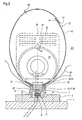
- Ein Ausführungsbeispiel der Erfindung ist in der Zeichnung dargestellt. Es zeigt:
- Figur 1
- einen aufgeblasenen Schwimmsack in einer Seitenansicht,
- Figur 2
- den Schwimmsack nach
Figur 1 in einer Vorderansicht. - An der Innenwand 1 eines Wasserfahrzeuges 3 ist an einer Montageplatte 5 ein Lagerfuß 7 über eine pyrotechnisch auslösbare Trennschraube 9 mit der Montageplatte 5 fest verbunden.
- In einem Hohlraum 11 des Lagerfußes 7 ist neben der Trennschraube 9 ein aufgewickeltes Seil 13 gelagert. Das Seil 13 ist mit der Montageplatte 5 als auch mit dem Lagerfuß 7 verbunden.
- In einem weiteren Hohlraum 15 des Lagerfußes 7 liegt ein zylindrischer Zapfen 17 eines Aufnahmekörpers 19.
- In einer zylindrischen, dünnwandigen Wanne 21 mit Flügeln 20 des Aufnahmekörpers 19 ist über einen Bereich 53 ein zylindrischer Gasgenerator 23 befestigt.
- Ein Packsack 25 hüllt sowohl einen zusammengefalteten, auf dem Gasgenerator 23 gelagerten Schwimmsack 27 als auch den darin angeordneten Gasgenerator 23 ein. Der Packsack 25 ist unterhalb eines aufgeweiteten Abschnitts 31 an dem Basiskörpers 7 gas- und wasserdicht befestigt.
- Der Schwimmsack 27 weist im Bereich 55 der geringsten Zugspannungen eine, durch einen Lappen 49 des Schwimmsacks 27 wasser- und gasdicht schließbare Öffnungen 50 zur Montage des Gasgenerators 23 und des Aufnahmekörpers 19 auf. Der Lappen 49 überlappt den Basissack 47 und ist bei 51 gas- und wasserdicht mit diesem verbunden.
- In einer Ausnehmung 33 ist ein Keder 35 des Schwimmsackes 27 gelagert. Die Ausnehmung 33 ist durch entsprechende Kehlnuten 37, 38 am Lagerfuß7 und am Aufnahmekörper 19 gebildet.
- Ein Überdruckventil 63 ist durch einen Pfeil symbolisch dargestellt.
- Zur Verdrängung des Wassers im Innenraum 2 wird der Gasgenerator 23 elektrisch gezündet. Der gefaltete Schwimmsack 27, der sich noch innerhalb des Packsackes 25 befindet, beginnt sich mit Gas zu füllen, wobei das Gas an einer Öffnung 41 des Gasgenerators 23 aus und in den Schwimmsack 27 direkt und unmittelbar eintritt.
- Aufgrund des zunehmenden Gasvolumens des Schwimmsackes 27 birst schließlich der Packsack 25 und der Schwimmsack 27 entfaltet sich bis zu seiner gezeichneten Endgröße. Das Wasser wird entsprechend verdrängt und der Auftrieb durch den gefüllten Schwimmsack 27 bewirkt.
Nach etwa 0,2 Sek. wird die Trennschraube 9 elektrisch gezündet und gibt den Lagerfuß 7 frei. Der Schwimmsack 27 mit Gasgenerator 23, Aufnahmekörper 19 und Lagerfuß 7 entfernt sich entsprechend seinem Auftrieb und der Länge des Seiles 13 von der Innenwand 1 und sucht sich seinen Platz im Innenraum 2. - Wesentlich ist für die Befestigung des Schwimmsacks ist, dass ab dem Keder 35 der Schwimmsack 27 durch die Außenfläche 22 der Flügel 20 der teilzylindrischen Wanne 21 geführt wird -
Figur 2 -. Schwankungen des Schwimmsackes 27 oder extreme Lageänderungen des Schwimmsackes 27 führen zu keinen Knicken am Schwimmsack 27. Es treten keine Schubspannungen am Schwimmsack 27 auf. Dazu trägt in einer um 90° versetzten Ebene auch der zylindrische Gasgenerator - sieheFigur 1 - als auch die Radien 43, 45 am Gasgenerator 23 bei. - Vorteilhaft ist auch, dass sich zwischen dem zylindrischen Gasgenerator 23 und dem Schwimmsack 27 sich mit Gas gefüllte Zwickel 61 bilden. Diese Zwickel 61 sind zusätzliches Auftriebsvolumen.
Claims (5)
- Modul als Auftriebshilfe für Wasserfahrzeuge (3) in Seenot mit einem, durch einen Gasgenerator (23) aufblasbaren Schwimmsack (27) zur Verwendung in einem Wasserfahrzeug (3), wobei
der Schwimmsack (27) mit dem Wasserfahrzeug (3) durch eine Fesselung (13) verbindbar ist, und
wobei der Schwimmsack (27) über einen Keder (35) mit einem, aus einem Zapfen (17) bestehenden Aufnahmekörper (19) und mit einem Lagerfuß (7) verbunden ist, so daß am Aufnahmekörper (19) der Keder (35) befestigt ist, dadurch gekennzeichnet, daß der im Innern des Schwimmsackes (27) angeordnete Gasgenerator (23) als Zylinder ausgebildet ist, der mit seinem zylindrischen Teilumfang (53) in einer dünnwandigen Wanne (21) des Aufnahmekörpers (19) innerhalb des Schwimmsackes (23) formschlüssig liegt und dort befestigt ist, wobei die Wanne (21) mit zwei Flügeln (20) beidseitig über den Zapfen (17) hinausragt und der Schwimmsack (27) ab dem Keder (35) an den Flügeln (20) anliegt, und daß der Lagerfuß (7) durch eine Trennschraube (9) lösbar mit dem Wasserfahrzeug (3) verbindbar, jedoch im abgelösten Zustand durch ein Seil (13) haltbar ist. - Modul nach Anspruch 1,
dadurch gekennzeichnet,
dass der Gasgenerator (23) mit seiner Öffnung (41) direkt an einer Öffnung des gefalteten Schwimmsackes (27) liegt. - Modul nach Anspruch 1,
dadurch gekennzeichnet,
dass der gefaltete Schwimmsack (27) direkt auf dem Gasgenerator (23) gelagert und durch eine zerstörbare Haube (25) gehalten ist. - Modul nach Anspruch 3,
dadurch gekennzeichnet,
dass die Haube (25) wasser- und gasdicht an dem Lagerfuß (7) befestigt ist. - Modul nach Anspruch 1,
dadurch gekennzeichnet,
dass der Schwimmsack (27) im Bereich der geringsten Zugspannungen eine, durch einen Lappen (49) des Schwimmsacks (27) wasser- und gasdicht schließbare Öffnung (50) zur Montage des Gasgenerators (23) aufweist.
Applications Claiming Priority (2)
| Application Number | Priority Date | Filing Date | Title |
|---|---|---|---|
| DE2003125696 DE10325696A1 (de) | 2003-06-06 | 2003-06-06 | Modul als Auftriebshilfe für Wasserfahrzeuge |
| PCT/EP2004/005981 WO2004108521A1 (de) | 2003-06-06 | 2004-06-03 | Modul als auftriebshilfe für wasserfahrzeuge |
Publications (2)
| Publication Number | Publication Date |
|---|---|
| EP1631491A1 EP1631491A1 (de) | 2006-03-08 |
| EP1631491B1 true EP1631491B1 (de) | 2008-05-14 |
Family
ID=33482634
Family Applications (1)
| Application Number | Title | Priority Date | Filing Date |
|---|---|---|---|
| EP04739554A Expired - Lifetime EP1631491B1 (de) | 2003-06-06 | 2004-06-03 | Modul als auftriebshilfe für wasserfahrzeuge |
Country Status (7)
| Country | Link |
|---|---|
| EP (1) | EP1631491B1 (de) |
| AU (1) | AU2004245217B2 (de) |
| DE (2) | DE10325696A1 (de) |
| ES (1) | ES2305784T3 (de) |
| IL (1) | IL172372A (de) |
| RU (1) | RU2337853C2 (de) |
| WO (1) | WO2004108521A1 (de) |
Families Citing this family (1)
| Publication number | Priority date | Publication date | Assignee | Title |
|---|---|---|---|---|
| CN113358101A (zh) * | 2021-05-07 | 2021-09-07 | 刘若冲 | 一种海洋洋流检测器的装配式保护装置 |
Family Cites Families (6)
| Publication number | Priority date | Publication date | Assignee | Title |
|---|---|---|---|---|
| DE570719C (de) * | 1930-11-11 | 1933-02-18 | Albert Eustace Short | Boje zur Verankerung von Booten und Wasserflugzeugen |
| FR878980A (fr) * | 1942-02-02 | 1943-02-10 | Procédé et appareil pour l'allègement ou le relevage des épaves | |
| US4232417A (en) * | 1979-01-24 | 1980-11-11 | The United States Of America As Represented By The Secretary Of The Navy | Marine mammal retrieval apparatus |
| SU1706914A1 (ru) * | 1990-03-13 | 1992-01-23 | Московский институт теплотехники | Устройство дл поддержани на плаву получившего пробоину судна |
| CA2077770A1 (en) * | 1992-10-01 | 1994-04-02 | John D. Barber | Boat floatation system |
| DE19752498C2 (de) * | 1997-11-27 | 2002-04-18 | Diehl Stiftung & Co | Auftriebshilfe für Wasserfahrzeuge |
-
2003
- 2003-06-06 DE DE2003125696 patent/DE10325696A1/de not_active Withdrawn
-
2004
- 2004-06-03 DE DE502004007148T patent/DE502004007148D1/de not_active Expired - Lifetime
- 2004-06-03 ES ES04739554T patent/ES2305784T3/es not_active Expired - Lifetime
- 2004-06-03 EP EP04739554A patent/EP1631491B1/de not_active Expired - Lifetime
- 2004-06-03 RU RU2005141511/11A patent/RU2337853C2/ru not_active IP Right Cessation
- 2004-06-03 WO PCT/EP2004/005981 patent/WO2004108521A1/de not_active Ceased
- 2004-06-03 AU AU2004245217A patent/AU2004245217B2/en not_active Ceased
-
2005
- 2005-12-05 IL IL172372A patent/IL172372A/en not_active IP Right Cessation
Also Published As
| Publication number | Publication date |
|---|---|
| EP1631491A1 (de) | 2006-03-08 |
| AU2004245217B2 (en) | 2010-09-16 |
| IL172372A (en) | 2010-11-30 |
| DE502004007148D1 (de) | 2008-06-26 |
| DE10325696A1 (de) | 2004-12-23 |
| RU2005141511A (ru) | 2006-06-10 |
| WO2004108521A1 (de) | 2004-12-16 |
| AU2004245217A1 (en) | 2004-12-16 |
| ES2305784T3 (es) | 2008-11-01 |
| RU2337853C2 (ru) | 2008-11-10 |
Similar Documents
| Publication | Publication Date | Title |
|---|---|---|
| CN204184558U (zh) | 水难救援装置 | |
| DE2213144C3 (de) | Schwimmzaun zur Eindämmung von auf der Wasseroberfläche schwimmenden Verunreinigungen, insbesondere von Öl | |
| EP0736450B1 (de) | Auftriebshilfe für Wasserfahrzeuge in Seenot | |
| DE2424648C3 (de) | Rettungsgerät für Schiffe | |
| EP2479105B1 (de) | Rettungsanzug für Unterseebootfahrer | |
| CN105539736A (zh) | 一种船舶救生装置的救生器 | |
| EP1631490B1 (de) | Auftriebshilfe für wasserfahrzeuge | |
| WO2004108521A1 (de) | Modul als auftriebshilfe für wasserfahrzeuge | |
| DE3210590A1 (de) | Rettungskoerper | |
| DE102010033522B4 (de) | Zweikomponenten-Rettungsgerät zur Sicherung und Rettung einer oder mehrerer im Wasser treibender Personen | |
| DE202012001200U1 (de) | Pneumatischer Zweikomponenten-Rettungsstern | |
| CN207311790U (zh) | 便携式水上救援设备 | |
| DE19752498A1 (de) | Auftriebshilfe für Wasserfahrzeuge | |
| EP0787234B1 (de) | Schwimmkörper | |
| DE19610417B4 (de) | Sicherungssystem für die in einem Laderaum eines Wasserfahrzeuges befindliche Ladung | |
| DE102008017742B4 (de) | Rettungsvorrichtung für einen MOB-Notfall | |
| DE2404272A1 (de) | Aufblasbares rettungsfloss oder schlauchboot | |
| DE19752499C2 (de) | Rettungssystem für Schiffe | |
| CN111204424A (zh) | 一种便于稳定的安全救生船 | |
| DE1972420U (de) | Vorrichtung zur rettung aus seenot. | |
| DE102013101287A1 (de) | Vorrichtung zum Heben eines auf Grund gelaufenen Schiffs | |
| DE2130866A1 (de) | Aufblasbares Rettungsfloss | |
| DE202010011090U1 (de) | Pneumatisches Zweikomponenten-Rettungsgerät zur Sicherung und Rettung einer oder mehrerer im Wasser treibender Personen | |
| DE19813579A1 (de) | Schwimmweste mit Signalvorrichtung | |
| DE10010884A1 (de) | Signalboje für Taucher |
Legal Events
| Date | Code | Title | Description |
|---|---|---|---|
| PUAI | Public reference made under article 153(3) epc to a published international application that has entered the european phase |
Free format text: ORIGINAL CODE: 0009012 |
|
| 17P | Request for examination filed |
Effective date: 20051209 |
|
| AK | Designated contracting states |
Kind code of ref document: A1 Designated state(s): DE ES FR GB SE |
|
| DAX | Request for extension of the european patent (deleted) | ||
| RBV | Designated contracting states (corrected) |
Designated state(s): DE ES FR GB SE |
|
| GRAP | Despatch of communication of intention to grant a patent |
Free format text: ORIGINAL CODE: EPIDOSNIGR1 |
|
| GRAS | Grant fee paid |
Free format text: ORIGINAL CODE: EPIDOSNIGR3 |
|
| GRAA | (expected) grant |
Free format text: ORIGINAL CODE: 0009210 |
|
| AK | Designated contracting states |
Kind code of ref document: B1 Designated state(s): DE ES FR GB SE |
|
| REG | Reference to a national code |
Ref country code: GB Ref legal event code: FG4D Free format text: NOT ENGLISH |
|
| REF | Corresponds to: |
Ref document number: 502004007148 Country of ref document: DE Date of ref document: 20080626 Kind code of ref document: P |
|
| REG | Reference to a national code |
Ref country code: SE Ref legal event code: TRGR |
|
| REG | Reference to a national code |
Ref country code: ES Ref legal event code: FG2A Ref document number: 2305784 Country of ref document: ES Kind code of ref document: T3 |
|
| PLBE | No opposition filed within time limit |
Free format text: ORIGINAL CODE: 0009261 |
|
| STAA | Information on the status of an ep patent application or granted ep patent |
Free format text: STATUS: NO OPPOSITION FILED WITHIN TIME LIMIT |
|
| 26N | No opposition filed |
Effective date: 20090217 |
|
| PGFP | Annual fee paid to national office [announced via postgrant information from national office to epo] |
Ref country code: FR Payment date: 20120705 Year of fee payment: 9 Ref country code: SE Payment date: 20120621 Year of fee payment: 9 Ref country code: GB Payment date: 20120622 Year of fee payment: 9 |
|
| PGFP | Annual fee paid to national office [announced via postgrant information from national office to epo] |
Ref country code: DE Payment date: 20120822 Year of fee payment: 9 Ref country code: ES Payment date: 20120627 Year of fee payment: 9 |
|
| PG25 | Lapsed in a contracting state [announced via postgrant information from national office to epo] |
Ref country code: SE Free format text: LAPSE BECAUSE OF NON-PAYMENT OF DUE FEES Effective date: 20130604 |
|
| REG | Reference to a national code |
Ref country code: SE Ref legal event code: EUG |
|
| GBPC | Gb: european patent ceased through non-payment of renewal fee |
Effective date: 20130603 |
|
| REG | Reference to a national code |
Ref country code: DE Ref legal event code: R119 Ref document number: 502004007148 Country of ref document: DE Effective date: 20140101 |
|
| REG | Reference to a national code |
Ref country code: FR Ref legal event code: ST Effective date: 20140228 |
|
| PG25 | Lapsed in a contracting state [announced via postgrant information from national office to epo] |
Ref country code: DE Free format text: LAPSE BECAUSE OF NON-PAYMENT OF DUE FEES Effective date: 20140101 Ref country code: GB Free format text: LAPSE BECAUSE OF NON-PAYMENT OF DUE FEES Effective date: 20130603 |
|
| PG25 | Lapsed in a contracting state [announced via postgrant information from national office to epo] |
Ref country code: FR Free format text: LAPSE BECAUSE OF NON-PAYMENT OF DUE FEES Effective date: 20130701 |
|
| REG | Reference to a national code |
Ref country code: ES Ref legal event code: FD2A Effective date: 20150709 |
|
| PG25 | Lapsed in a contracting state [announced via postgrant information from national office to epo] |
Ref country code: ES Free format text: LAPSE BECAUSE OF NON-PAYMENT OF DUE FEES Effective date: 20130604 |