EP1628567B1 - Method and apparatus for fluid injection - Google Patents
Method and apparatus for fluid injection Download PDFInfo
- Publication number
- EP1628567B1 EP1628567B1 EP04754025A EP04754025A EP1628567B1 EP 1628567 B1 EP1628567 B1 EP 1628567B1 EP 04754025 A EP04754025 A EP 04754025A EP 04754025 A EP04754025 A EP 04754025A EP 1628567 B1 EP1628567 B1 EP 1628567B1
- Authority
- EP
- European Patent Office
- Prior art keywords
- penetrating member
- cartridge
- penetrating
- members
- driver
- Prior art date
- Legal status (The legal status is an assumption and is not a legal conclusion. Google has not performed a legal analysis and makes no representation as to the accuracy of the status listed.)
- Not-in-force
Links
- 239000012530 fluid Substances 0.000 title claims description 49
- 238000000034 method Methods 0.000 title description 58
- 238000002347 injection Methods 0.000 title description 32
- 239000007924 injection Substances 0.000 title description 32
- 230000000149 penetrating effect Effects 0.000 claims abstract description 956
- 238000005070 sampling Methods 0.000 claims abstract description 50
- 210000001124 body fluid Anatomy 0.000 claims abstract description 31
- 239000010839 body fluid Substances 0.000 claims abstract description 31
- 210000001519 tissue Anatomy 0.000 claims description 96
- 210000003491 skin Anatomy 0.000 claims description 95
- 210000004207 dermis Anatomy 0.000 claims description 12
- 210000002615 epidermis Anatomy 0.000 claims description 9
- 230000037324 pain perception Effects 0.000 claims description 3
- 230000007383 nerve stimulation Effects 0.000 claims description 2
- 239000012491 analyte Substances 0.000 description 187
- 230000004888 barrier function Effects 0.000 description 73
- 239000000463 material Substances 0.000 description 67
- 230000035515 penetration Effects 0.000 description 60
- 230000036512 infertility Effects 0.000 description 58
- 230000033001 locomotion Effects 0.000 description 47
- 210000004369 blood Anatomy 0.000 description 45
- 239000008280 blood Substances 0.000 description 45
- 230000007246 mechanism Effects 0.000 description 40
- 230000003287 optical effect Effects 0.000 description 37
- 238000012360 testing method Methods 0.000 description 34
- 239000011888 foil Substances 0.000 description 31
- 239000003795 chemical substances by application Substances 0.000 description 29
- XEEYBQQBJWHFJM-UHFFFAOYSA-N Iron Chemical compound [Fe] XEEYBQQBJWHFJM-UHFFFAOYSA-N 0.000 description 28
- 239000003814 drug Substances 0.000 description 28
- 229940079593 drug Drugs 0.000 description 28
- 238000005520 cutting process Methods 0.000 description 26
- 238000006073 displacement reaction Methods 0.000 description 25
- 210000000434 stratum corneum Anatomy 0.000 description 21
- 238000003780 insertion Methods 0.000 description 16
- 230000037431 insertion Effects 0.000 description 16
- 239000000758 substrate Substances 0.000 description 16
- 238000000576 coating method Methods 0.000 description 15
- 230000036407 pain Effects 0.000 description 15
- 230000001965 increasing effect Effects 0.000 description 14
- 229910052742 iron Inorganic materials 0.000 description 13
- 238000011068 loading method Methods 0.000 description 13
- 238000005259 measurement Methods 0.000 description 13
- 230000001954 sterilising effect Effects 0.000 description 13
- 238000004659 sterilization and disinfection Methods 0.000 description 13
- 238000004458 analytical method Methods 0.000 description 12
- 239000011248 coating agent Substances 0.000 description 12
- 238000007373 indentation Methods 0.000 description 12
- 230000008569 process Effects 0.000 description 12
- 230000008901 benefit Effects 0.000 description 11
- 238000001514 detection method Methods 0.000 description 11
- 230000001681 protective effect Effects 0.000 description 11
- 230000002829 reductive effect Effects 0.000 description 11
- 238000013461 design Methods 0.000 description 10
- 230000005284 excitation Effects 0.000 description 10
- 239000003990 capacitor Substances 0.000 description 9
- 230000001276 controlling effect Effects 0.000 description 9
- 229910001220 stainless steel Inorganic materials 0.000 description 9
- 239000010935 stainless steel Substances 0.000 description 9
- 230000008878 coupling Effects 0.000 description 8
- 238000010168 coupling process Methods 0.000 description 8
- 238000005859 coupling reaction Methods 0.000 description 8
- 238000004519 manufacturing process Methods 0.000 description 8
- 229910052751 metal Inorganic materials 0.000 description 8
- 239000002184 metal Substances 0.000 description 8
- 239000002070 nanowire Substances 0.000 description 8
- 239000004033 plastic Substances 0.000 description 8
- 230000001133 acceleration Effects 0.000 description 7
- 230000006835 compression Effects 0.000 description 7
- 238000007906 compression Methods 0.000 description 7
- 238000012377 drug delivery Methods 0.000 description 7
- 238000005286 illumination Methods 0.000 description 7
- 230000035945 sensitivity Effects 0.000 description 7
- 238000000926 separation method Methods 0.000 description 7
- 238000003860 storage Methods 0.000 description 7
- WQZGKKKJIJFFOK-GASJEMHNSA-N Glucose Natural products OC[C@H]1OC(O)[C@H](O)[C@@H](O)[C@@H]1O WQZGKKKJIJFFOK-GASJEMHNSA-N 0.000 description 6
- 230000009471 action Effects 0.000 description 6
- 230000008859 change Effects 0.000 description 6
- 239000008103 glucose Substances 0.000 description 6
- 230000003993 interaction Effects 0.000 description 6
- 238000004804 winding Methods 0.000 description 6
- 239000003153 chemical reaction reagent Substances 0.000 description 5
- 238000005516 engineering process Methods 0.000 description 5
- 238000010304 firing Methods 0.000 description 5
- 230000036961 partial effect Effects 0.000 description 5
- 239000002245 particle Substances 0.000 description 5
- 229920000642 polymer Polymers 0.000 description 5
- 229960005486 vaccine Drugs 0.000 description 5
- 229910000831 Steel Inorganic materials 0.000 description 4
- 238000013459 approach Methods 0.000 description 4
- 210000004204 blood vessel Anatomy 0.000 description 4
- 210000004027 cell Anatomy 0.000 description 4
- 230000000994 depressogenic effect Effects 0.000 description 4
- 230000006870 function Effects 0.000 description 4
- 230000001976 improved effect Effects 0.000 description 4
- 238000004806 packaging method and process Methods 0.000 description 4
- -1 polytetrafluoroethylene Polymers 0.000 description 4
- 230000004044 response Effects 0.000 description 4
- 230000003068 static effect Effects 0.000 description 4
- 239000010959 steel Substances 0.000 description 4
- 230000003797 telogen phase Effects 0.000 description 4
- GYTROFMCUJZKNA-UHFFFAOYSA-N triethyl triethoxysilyl silicate Chemical compound CCO[Si](OCC)(OCC)O[Si](OCC)(OCC)OCC GYTROFMCUJZKNA-UHFFFAOYSA-N 0.000 description 4
- 230000000007 visual effect Effects 0.000 description 4
- RYGMFSIKBFXOCR-UHFFFAOYSA-N Copper Chemical compound [Cu] RYGMFSIKBFXOCR-UHFFFAOYSA-N 0.000 description 3
- 241000237858 Gastropoda Species 0.000 description 3
- 108010015776 Glucose oxidase Proteins 0.000 description 3
- 239000004366 Glucose oxidase Substances 0.000 description 3
- 229910045601 alloy Inorganic materials 0.000 description 3
- 239000000956 alloy Substances 0.000 description 3
- 210000003484 anatomy Anatomy 0.000 description 3
- 239000000427 antigen Substances 0.000 description 3
- 108091007433 antigens Proteins 0.000 description 3
- 102000036639 antigens Human genes 0.000 description 3
- 239000004020 conductor Substances 0.000 description 3
- 238000002788 crimping Methods 0.000 description 3
- 230000003247 decreasing effect Effects 0.000 description 3
- 229910003460 diamond Inorganic materials 0.000 description 3
- 239000010432 diamond Substances 0.000 description 3
- 238000003708 edge detection Methods 0.000 description 3
- 229920001971 elastomer Polymers 0.000 description 3
- 229940116332 glucose oxidase Drugs 0.000 description 3
- 235000019420 glucose oxidase Nutrition 0.000 description 3
- 230000036571 hydration Effects 0.000 description 3
- 238000006703 hydration reaction Methods 0.000 description 3
- 239000007788 liquid Substances 0.000 description 3
- 239000000696 magnetic material Substances 0.000 description 3
- 239000000203 mixture Substances 0.000 description 3
- 238000012544 monitoring process Methods 0.000 description 3
- 229920001343 polytetrafluoroethylene Polymers 0.000 description 3
- 239000004810 polytetrafluoroethylene Substances 0.000 description 3
- 238000007789 sealing Methods 0.000 description 3
- 210000000437 stratum spinosum Anatomy 0.000 description 3
- VGGSQFUCUMXWEO-UHFFFAOYSA-N Ethene Chemical compound C=C VGGSQFUCUMXWEO-UHFFFAOYSA-N 0.000 description 2
- 239000005977 Ethylene Substances 0.000 description 2
- CWYNVVGOOAEACU-UHFFFAOYSA-N Fe2+ Chemical compound [Fe+2] CWYNVVGOOAEACU-UHFFFAOYSA-N 0.000 description 2
- 239000000853 adhesive Substances 0.000 description 2
- 230000001070 adhesive effect Effects 0.000 description 2
- 229910052782 aluminium Inorganic materials 0.000 description 2
- XAGFODPZIPBFFR-UHFFFAOYSA-N aluminium Chemical compound [Al] XAGFODPZIPBFFR-UHFFFAOYSA-N 0.000 description 2
- 238000005452 bending Methods 0.000 description 2
- 230000015572 biosynthetic process Effects 0.000 description 2
- 238000005229 chemical vapour deposition Methods 0.000 description 2
- 238000004891 communication Methods 0.000 description 2
- 239000000356 contaminant Substances 0.000 description 2
- 238000011109 contamination Methods 0.000 description 2
- 229920001577 copolymer Polymers 0.000 description 2
- 238000010586 diagram Methods 0.000 description 2
- 238000002651 drug therapy Methods 0.000 description 2
- 230000009977 dual effect Effects 0.000 description 2
- 230000002500 effect on skin Effects 0.000 description 2
- 230000000694 effects Effects 0.000 description 2
- 230000005672 electromagnetic field Effects 0.000 description 2
- 229920005570 flexible polymer Polymers 0.000 description 2
- 230000004907 flux Effects 0.000 description 2
- 238000005755 formation reaction Methods 0.000 description 2
- 239000007789 gas Substances 0.000 description 2
- PCHJSUWPFVWCPO-UHFFFAOYSA-N gold Chemical compound [Au] PCHJSUWPFVWCPO-UHFFFAOYSA-N 0.000 description 2
- 229910052737 gold Inorganic materials 0.000 description 2
- 239000010931 gold Substances 0.000 description 2
- 230000005484 gravity Effects 0.000 description 2
- 230000001939 inductive effect Effects 0.000 description 2
- 239000011553 magnetic fluid Substances 0.000 description 2
- 230000004048 modification Effects 0.000 description 2
- 238000012986 modification Methods 0.000 description 2
- 239000002071 nanotube Substances 0.000 description 2
- 239000003921 oil Substances 0.000 description 2
- 210000000056 organ Anatomy 0.000 description 2
- 238000012856 packing Methods 0.000 description 2
- 230000010412 perfusion Effects 0.000 description 2
- BASFCYQUMIYNBI-UHFFFAOYSA-N platinum Chemical compound [Pt] BASFCYQUMIYNBI-UHFFFAOYSA-N 0.000 description 2
- 229920001296 polysiloxane Polymers 0.000 description 2
- 238000004080 punching Methods 0.000 description 2
- 230000009467 reduction Effects 0.000 description 2
- 238000005096 rolling process Methods 0.000 description 2
- 229910052709 silver Inorganic materials 0.000 description 2
- 239000004332 silver Substances 0.000 description 2
- 230000036555 skin type Effects 0.000 description 2
- 239000000243 solution Substances 0.000 description 2
- 210000000438 stratum basale Anatomy 0.000 description 2
- 210000000498 stratum granulosum Anatomy 0.000 description 2
- 210000000439 stratum lucidum Anatomy 0.000 description 2
- 238000006467 substitution reaction Methods 0.000 description 2
- 238000003466 welding Methods 0.000 description 2
- 229910000859 α-Fe Inorganic materials 0.000 description 2
- 206010002091 Anaesthesia Diseases 0.000 description 1
- OKTJSMMVPCPJKN-UHFFFAOYSA-N Carbon Chemical compound [C] OKTJSMMVPCPJKN-UHFFFAOYSA-N 0.000 description 1
- 229910000975 Carbon steel Inorganic materials 0.000 description 1
- 102000007644 Colony-Stimulating Factors Human genes 0.000 description 1
- 108010071942 Colony-Stimulating Factors Proteins 0.000 description 1
- 108090000695 Cytokines Proteins 0.000 description 1
- 102000004127 Cytokines Human genes 0.000 description 1
- 101150027068 DEGS1 gene Proteins 0.000 description 1
- 108090000790 Enzymes Proteins 0.000 description 1
- 102000004190 Enzymes Human genes 0.000 description 1
- 239000004593 Epoxy Substances 0.000 description 1
- 239000004812 Fluorinated ethylene propylene Substances 0.000 description 1
- WHXSMMKQMYFTQS-UHFFFAOYSA-N Lithium Chemical compound [Li] WHXSMMKQMYFTQS-UHFFFAOYSA-N 0.000 description 1
- 206010028980 Neoplasm Diseases 0.000 description 1
- 229920001774 Perfluoroether Polymers 0.000 description 1
- 230000006978 adaptation Effects 0.000 description 1
- 238000007792 addition Methods 0.000 description 1
- 230000037005 anaesthesia Effects 0.000 description 1
- 229940035676 analgesics Drugs 0.000 description 1
- 239000000730 antalgic agent Substances 0.000 description 1
- 239000003146 anticoagulant agent Substances 0.000 description 1
- 229940127219 anticoagulant drug Drugs 0.000 description 1
- 238000003491 array Methods 0.000 description 1
- 238000000418 atomic force spectrum Methods 0.000 description 1
- QVGXLLKOCUKJST-UHFFFAOYSA-N atomic oxygen Chemical compound [O] QVGXLLKOCUKJST-UHFFFAOYSA-N 0.000 description 1
- 230000004323 axial length Effects 0.000 description 1
- 239000011324 bead Substances 0.000 description 1
- 239000012867 bioactive agent Substances 0.000 description 1
- 230000017531 blood circulation Effects 0.000 description 1
- 238000010241 blood sampling Methods 0.000 description 1
- 238000004364 calculation method Methods 0.000 description 1
- 239000002041 carbon nanotube Substances 0.000 description 1
- 229910021393 carbon nanotube Inorganic materials 0.000 description 1
- 239000010962 carbon steel Substances 0.000 description 1
- 239000000919 ceramic Substances 0.000 description 1
- 238000007705 chemical test Methods 0.000 description 1
- UUAGAQFQZIEFAH-UHFFFAOYSA-N chlorotrifluoroethylene Chemical group FC(F)=C(F)Cl UUAGAQFQZIEFAH-UHFFFAOYSA-N 0.000 description 1
- 239000003086 colorant Substances 0.000 description 1
- 229940000425 combination drug Drugs 0.000 description 1
- 239000002131 composite material Substances 0.000 description 1
- 239000012141 concentrate Substances 0.000 description 1
- 230000008602 contraction Effects 0.000 description 1
- 238000003869 coulometry Methods 0.000 description 1
- 238000013016 damping Methods 0.000 description 1
- 230000002950 deficient Effects 0.000 description 1
- 238000012217 deletion Methods 0.000 description 1
- 230000037430 deletion Effects 0.000 description 1
- 229940124447 delivery agent Drugs 0.000 description 1
- 238000000151 deposition Methods 0.000 description 1
- 206010012601 diabetes mellitus Diseases 0.000 description 1
- 239000000428 dust Substances 0.000 description 1
- 239000000975 dye Substances 0.000 description 1
- 239000000806 elastomer Substances 0.000 description 1
- 230000005684 electric field Effects 0.000 description 1
- 229940088598 enzyme Drugs 0.000 description 1
- HQQADJVZYDDRJT-UHFFFAOYSA-N ethene;prop-1-ene Chemical group C=C.CC=C HQQADJVZYDDRJT-UHFFFAOYSA-N 0.000 description 1
- 238000002474 experimental method Methods 0.000 description 1
- 239000000284 extract Substances 0.000 description 1
- 239000011554 ferrofluid Substances 0.000 description 1
- 230000005669 field effect Effects 0.000 description 1
- 238000011049 filling Methods 0.000 description 1
- 238000001415 gene therapy Methods 0.000 description 1
- 239000011521 glass Substances 0.000 description 1
- 230000003760 hair shine Effects 0.000 description 1
- 238000010438 heat treatment Methods 0.000 description 1
- 230000003100 immobilizing effect Effects 0.000 description 1
- 238000009169 immunotherapy Methods 0.000 description 1
- 230000003116 impacting effect Effects 0.000 description 1
- 230000006872 improvement Effects 0.000 description 1
- 229910052738 indium Inorganic materials 0.000 description 1
- 239000003999 initiator Substances 0.000 description 1
- 230000030214 innervation Effects 0.000 description 1
- 230000010354 integration Effects 0.000 description 1
- 230000002452 interceptive effect Effects 0.000 description 1
- 229910052744 lithium Inorganic materials 0.000 description 1
- 230000007774 longterm Effects 0.000 description 1
- 210000004880 lymph fluid Anatomy 0.000 description 1
- 238000000691 measurement method Methods 0.000 description 1
- 210000000412 mechanoreceptor Anatomy 0.000 description 1
- 150000002739 metals Chemical class 0.000 description 1
- 238000002156 mixing Methods 0.000 description 1
- 238000012806 monitoring device Methods 0.000 description 1
- 230000008450 motivation Effects 0.000 description 1
- 238000000465 moulding Methods 0.000 description 1
- 210000000929 nociceptor Anatomy 0.000 description 1
- 229910052760 oxygen Inorganic materials 0.000 description 1
- 239000001301 oxygen Substances 0.000 description 1
- 230000001575 pathological effect Effects 0.000 description 1
- 230000037361 pathway Effects 0.000 description 1
- 229920009441 perflouroethylene propylene Polymers 0.000 description 1
- 230000002093 peripheral effect Effects 0.000 description 1
- 230000000704 physical effect Effects 0.000 description 1
- 229910052697 platinum Inorganic materials 0.000 description 1
- 239000000843 powder Substances 0.000 description 1
- 238000003825 pressing Methods 0.000 description 1
- 230000002035 prolonged effect Effects 0.000 description 1
- 230000002285 radioactive effect Effects 0.000 description 1
- 238000011084 recovery Methods 0.000 description 1
- 230000001105 regulatory effect Effects 0.000 description 1
- 239000002990 reinforced plastic Substances 0.000 description 1
- 239000012858 resilient material Substances 0.000 description 1
- 230000027756 respiratory electron transport chain Effects 0.000 description 1
- 230000000630 rising effect Effects 0.000 description 1
- 229910001285 shape-memory alloy Inorganic materials 0.000 description 1
- 238000007493 shaping process Methods 0.000 description 1
- 230000035939 shock Effects 0.000 description 1
- 229910052710 silicon Inorganic materials 0.000 description 1
- 239000010703 silicon Substances 0.000 description 1
- 238000005549 size reduction Methods 0.000 description 1
- 230000037067 skin hydration Effects 0.000 description 1
- 239000007787 solid Substances 0.000 description 1
- 238000009987 spinning Methods 0.000 description 1
- 230000002269 spontaneous effect Effects 0.000 description 1
- 230000004936 stimulating effect Effects 0.000 description 1
- 230000000638 stimulation Effects 0.000 description 1
- 238000010254 subcutaneous injection Methods 0.000 description 1
- 239000007929 subcutaneous injection Substances 0.000 description 1
- 239000000126 substance Substances 0.000 description 1
- 230000001360 synchronised effect Effects 0.000 description 1
- 230000008685 targeting Effects 0.000 description 1
- BFKJFAAPBSQJPD-UHFFFAOYSA-N tetrafluoroethene Chemical group FC(F)=C(F)F BFKJFAAPBSQJPD-UHFFFAOYSA-N 0.000 description 1
- 230000036962 time dependent Effects 0.000 description 1
- 230000001960 triggered effect Effects 0.000 description 1
- 238000002255 vaccination Methods 0.000 description 1
- 239000013598 vector Substances 0.000 description 1
- 239000002699 waste material Substances 0.000 description 1
Images


Classifications
-
- A—HUMAN NECESSITIES
- A61—MEDICAL OR VETERINARY SCIENCE; HYGIENE
- A61B—DIAGNOSIS; SURGERY; IDENTIFICATION
- A61B5/00—Measuring for diagnostic purposes; Identification of persons
- A61B5/15—Devices for taking samples of blood
- A61B5/157—Devices characterised by integrated means for measuring characteristics of blood
-
- A—HUMAN NECESSITIES
- A61—MEDICAL OR VETERINARY SCIENCE; HYGIENE
- A61B—DIAGNOSIS; SURGERY; IDENTIFICATION
- A61B5/00—Measuring for diagnostic purposes; Identification of persons
- A61B5/15—Devices for taking samples of blood
- A61B5/150007—Details
- A61B5/150015—Source of blood
- A61B5/150022—Source of blood for capillary blood or interstitial fluid
-
- A—HUMAN NECESSITIES
- A61—MEDICAL OR VETERINARY SCIENCE; HYGIENE
- A61B—DIAGNOSIS; SURGERY; IDENTIFICATION
- A61B5/00—Measuring for diagnostic purposes; Identification of persons
- A61B5/15—Devices for taking samples of blood
- A61B5/150007—Details
- A61B5/150053—Details for enhanced collection of blood or interstitial fluid at the sample site, e.g. by applying compression, heat, vibration, ultrasound, suction or vacuum to tissue; for reduction of pain or discomfort; Skin piercing elements, e.g. blades, needles, lancets or canulas, with adjustable piercing speed
- A61B5/150106—Means for reducing pain or discomfort applied before puncturing; desensitising the skin at the location where body is to be pierced
- A61B5/150152—Means for reducing pain or discomfort applied before puncturing; desensitising the skin at the location where body is to be pierced by an adequate mechanical impact on the puncturing location
-
- A—HUMAN NECESSITIES
- A61—MEDICAL OR VETERINARY SCIENCE; HYGIENE
- A61B—DIAGNOSIS; SURGERY; IDENTIFICATION
- A61B5/00—Measuring for diagnostic purposes; Identification of persons
- A61B5/15—Devices for taking samples of blood
- A61B5/150007—Details
- A61B5/150053—Details for enhanced collection of blood or interstitial fluid at the sample site, e.g. by applying compression, heat, vibration, ultrasound, suction or vacuum to tissue; for reduction of pain or discomfort; Skin piercing elements, e.g. blades, needles, lancets or canulas, with adjustable piercing speed
- A61B5/150167—Adjustable piercing speed of skin piercing element, e.g. blade, needle, lancet or canula, for example with varying spring force or pneumatic drive
-
- A—HUMAN NECESSITIES
- A61—MEDICAL OR VETERINARY SCIENCE; HYGIENE
- A61B—DIAGNOSIS; SURGERY; IDENTIFICATION
- A61B5/00—Measuring for diagnostic purposes; Identification of persons
- A61B5/15—Devices for taking samples of blood
- A61B5/150007—Details
- A61B5/150175—Adjustment of penetration depth
- A61B5/150183—Depth adjustment mechanism using end caps mounted at the distal end of the sampling device, i.e. the end-caps are adjustably positioned relative to the piercing device housing for example by rotating or screwing
-
- A—HUMAN NECESSITIES
- A61—MEDICAL OR VETERINARY SCIENCE; HYGIENE
- A61B—DIAGNOSIS; SURGERY; IDENTIFICATION
- A61B5/00—Measuring for diagnostic purposes; Identification of persons
- A61B5/15—Devices for taking samples of blood
- A61B5/150007—Details
- A61B5/150206—Construction or design features not otherwise provided for; manufacturing or production; packages; sterilisation of piercing element, piercing device or sampling device
- A61B5/150305—Packages specially adapted for piercing devices or blood sampling devices
-
- A—HUMAN NECESSITIES
- A61—MEDICAL OR VETERINARY SCIENCE; HYGIENE
- A61B—DIAGNOSIS; SURGERY; IDENTIFICATION
- A61B5/00—Measuring for diagnostic purposes; Identification of persons
- A61B5/15—Devices for taking samples of blood
- A61B5/150007—Details
- A61B5/150358—Strips for collecting blood, e.g. absorbent
-
- A—HUMAN NECESSITIES
- A61—MEDICAL OR VETERINARY SCIENCE; HYGIENE
- A61B—DIAGNOSIS; SURGERY; IDENTIFICATION
- A61B5/00—Measuring for diagnostic purposes; Identification of persons
- A61B5/15—Devices for taking samples of blood
- A61B5/150007—Details
- A61B5/150374—Details of piercing elements or protective means for preventing accidental injuries by such piercing elements
- A61B5/150381—Design of piercing elements
- A61B5/150412—Pointed piercing elements, e.g. needles, lancets for piercing the skin
-
- A—HUMAN NECESSITIES
- A61—MEDICAL OR VETERINARY SCIENCE; HYGIENE
- A61B—DIAGNOSIS; SURGERY; IDENTIFICATION
- A61B5/00—Measuring for diagnostic purposes; Identification of persons
- A61B5/15—Devices for taking samples of blood
- A61B5/150007—Details
- A61B5/150801—Means for facilitating use, e.g. by people with impaired vision; means for indicating when used correctly or incorrectly; means for alarming
- A61B5/150824—Means for facilitating use, e.g. by people with impaired vision; means for indicating when used correctly or incorrectly; means for alarming by visual feedback
-
- A—HUMAN NECESSITIES
- A61—MEDICAL OR VETERINARY SCIENCE; HYGIENE
- A61B—DIAGNOSIS; SURGERY; IDENTIFICATION
- A61B5/00—Measuring for diagnostic purposes; Identification of persons
- A61B5/15—Devices for taking samples of blood
- A61B5/150007—Details
- A61B5/150954—Means for the detection of operative contact with patient, e.g. by temperature sensitive sensor
-
- A—HUMAN NECESSITIES
- A61—MEDICAL OR VETERINARY SCIENCE; HYGIENE
- A61B—DIAGNOSIS; SURGERY; IDENTIFICATION
- A61B5/00—Measuring for diagnostic purposes; Identification of persons
- A61B5/15—Devices for taking samples of blood
- A61B5/151—Devices specially adapted for taking samples of capillary blood, e.g. by lancets, needles or blades
- A61B5/15101—Details
- A61B5/15103—Piercing procedure
- A61B5/15107—Piercing being assisted by a triggering mechanism
- A61B5/15113—Manually triggered, i.e. the triggering requires a deliberate action by the user such as pressing a drive button
-
- A—HUMAN NECESSITIES
- A61—MEDICAL OR VETERINARY SCIENCE; HYGIENE
- A61B—DIAGNOSIS; SURGERY; IDENTIFICATION
- A61B5/00—Measuring for diagnostic purposes; Identification of persons
- A61B5/15—Devices for taking samples of blood
- A61B5/151—Devices specially adapted for taking samples of capillary blood, e.g. by lancets, needles or blades
- A61B5/15101—Details
- A61B5/15115—Driving means for propelling the piercing element to pierce the skin, e.g. comprising mechanisms based on shape memory alloys, magnetism, solenoids, piezoelectric effect, biased elements, resilient elements, vacuum or compressed fluids
- A61B5/15117—Driving means for propelling the piercing element to pierce the skin, e.g. comprising mechanisms based on shape memory alloys, magnetism, solenoids, piezoelectric effect, biased elements, resilient elements, vacuum or compressed fluids comprising biased elements, resilient elements or a spring, e.g. a helical spring, leaf spring, or elastic strap
-
- A—HUMAN NECESSITIES
- A61—MEDICAL OR VETERINARY SCIENCE; HYGIENE
- A61B—DIAGNOSIS; SURGERY; IDENTIFICATION
- A61B5/00—Measuring for diagnostic purposes; Identification of persons
- A61B5/15—Devices for taking samples of blood
- A61B5/151—Devices specially adapted for taking samples of capillary blood, e.g. by lancets, needles or blades
- A61B5/15101—Details
- A61B5/15115—Driving means for propelling the piercing element to pierce the skin, e.g. comprising mechanisms based on shape memory alloys, magnetism, solenoids, piezoelectric effect, biased elements, resilient elements, vacuum or compressed fluids
- A61B5/15123—Driving means for propelling the piercing element to pierce the skin, e.g. comprising mechanisms based on shape memory alloys, magnetism, solenoids, piezoelectric effect, biased elements, resilient elements, vacuum or compressed fluids comprising magnets or solenoids
-
- A—HUMAN NECESSITIES
- A61—MEDICAL OR VETERINARY SCIENCE; HYGIENE
- A61B—DIAGNOSIS; SURGERY; IDENTIFICATION
- A61B5/00—Measuring for diagnostic purposes; Identification of persons
- A61B5/15—Devices for taking samples of blood
- A61B5/151—Devices specially adapted for taking samples of capillary blood, e.g. by lancets, needles or blades
- A61B5/15101—Details
- A61B5/15126—Means for controlling the lancing movement, e.g. 2D- or 3D-shaped elements, tooth-shaped elements or sliding guides
- A61B5/1513—Means for controlling the lancing movement, e.g. 2D- or 3D-shaped elements, tooth-shaped elements or sliding guides comprising linear sliding guides
-
- A—HUMAN NECESSITIES
- A61—MEDICAL OR VETERINARY SCIENCE; HYGIENE
- A61B—DIAGNOSIS; SURGERY; IDENTIFICATION
- A61B5/00—Measuring for diagnostic purposes; Identification of persons
- A61B5/15—Devices for taking samples of blood
- A61B5/151—Devices specially adapted for taking samples of capillary blood, e.g. by lancets, needles or blades
- A61B5/15146—Devices loaded with multiple lancets simultaneously, e.g. for serial firing without reloading, for example by use of stocking means.
- A61B5/15148—Constructional features of stocking means, e.g. strip, roll, disc, cartridge, belt or tube
- A61B5/15149—Arrangement of piercing elements relative to each other
- A61B5/15151—Each piercing element being stocked in a separate isolated compartment
-
- A—HUMAN NECESSITIES
- A61—MEDICAL OR VETERINARY SCIENCE; HYGIENE
- A61B—DIAGNOSIS; SURGERY; IDENTIFICATION
- A61B5/00—Measuring for diagnostic purposes; Identification of persons
- A61B5/15—Devices for taking samples of blood
- A61B5/151—Devices specially adapted for taking samples of capillary blood, e.g. by lancets, needles or blades
- A61B5/15146—Devices loaded with multiple lancets simultaneously, e.g. for serial firing without reloading, for example by use of stocking means.
- A61B5/15148—Constructional features of stocking means, e.g. strip, roll, disc, cartridge, belt or tube
- A61B5/15157—Geometry of stocking means or arrangement of piercing elements therein
- A61B5/15159—Piercing elements stocked in or on a disc
- A61B5/15161—Characterized by propelling the piercing element in a radial direction relative to the disc
-
- A—HUMAN NECESSITIES
- A61—MEDICAL OR VETERINARY SCIENCE; HYGIENE
- A61B—DIAGNOSIS; SURGERY; IDENTIFICATION
- A61B5/00—Measuring for diagnostic purposes; Identification of persons
- A61B5/15—Devices for taking samples of blood
- A61B5/151—Devices specially adapted for taking samples of capillary blood, e.g. by lancets, needles or blades
- A61B5/15146—Devices loaded with multiple lancets simultaneously, e.g. for serial firing without reloading, for example by use of stocking means.
- A61B5/15148—Constructional features of stocking means, e.g. strip, roll, disc, cartridge, belt or tube
- A61B5/15157—Geometry of stocking means or arrangement of piercing elements therein
- A61B5/15165—Piercing elements stocked in or on a strip
- A61B5/15169—Characterized by a rolled strip
-
- A—HUMAN NECESSITIES
- A61—MEDICAL OR VETERINARY SCIENCE; HYGIENE
- A61B—DIAGNOSIS; SURGERY; IDENTIFICATION
- A61B5/00—Measuring for diagnostic purposes; Identification of persons
- A61B5/15—Devices for taking samples of blood
- A61B5/151—Devices specially adapted for taking samples of capillary blood, e.g. by lancets, needles or blades
- A61B5/15146—Devices loaded with multiple lancets simultaneously, e.g. for serial firing without reloading, for example by use of stocking means.
- A61B5/15148—Constructional features of stocking means, e.g. strip, roll, disc, cartridge, belt or tube
- A61B5/15157—Geometry of stocking means or arrangement of piercing elements therein
- A61B5/15165—Piercing elements stocked in or on a strip
- A61B5/15171—Characterized by propelling the piercing element perpendicular to the direction of movement of the strip
-
- A—HUMAN NECESSITIES
- A61—MEDICAL OR VETERINARY SCIENCE; HYGIENE
- A61B—DIAGNOSIS; SURGERY; IDENTIFICATION
- A61B5/00—Measuring for diagnostic purposes; Identification of persons
- A61B5/15—Devices for taking samples of blood
- A61B5/151—Devices specially adapted for taking samples of capillary blood, e.g. by lancets, needles or blades
- A61B5/15146—Devices loaded with multiple lancets simultaneously, e.g. for serial firing without reloading, for example by use of stocking means.
- A61B5/15148—Constructional features of stocking means, e.g. strip, roll, disc, cartridge, belt or tube
- A61B5/15176—Stocking means comprising cap, cover, sheath or protection for aseptic stocking
-
- A—HUMAN NECESSITIES
- A61—MEDICAL OR VETERINARY SCIENCE; HYGIENE
- A61B—DIAGNOSIS; SURGERY; IDENTIFICATION
- A61B5/00—Measuring for diagnostic purposes; Identification of persons
- A61B5/15—Devices for taking samples of blood
- A61B5/151—Devices specially adapted for taking samples of capillary blood, e.g. by lancets, needles or blades
- A61B5/15146—Devices loaded with multiple lancets simultaneously, e.g. for serial firing without reloading, for example by use of stocking means.
- A61B5/15182—Means for keeping track or checking of the total number of piercing elements already used or the number of piercing elements still remaining in the stocking, e.g. by check window, counter, display
-
- A—HUMAN NECESSITIES
- A61—MEDICAL OR VETERINARY SCIENCE; HYGIENE
- A61B—DIAGNOSIS; SURGERY; IDENTIFICATION
- A61B5/00—Measuring for diagnostic purposes; Identification of persons
- A61B5/74—Details of notification to user or communication with user or patient ; user input means
- A61B5/742—Details of notification to user or communication with user or patient ; user input means using visual displays
- A61B5/7445—Display arrangements, e.g. multiple display units
-
- A—HUMAN NECESSITIES
- A61—MEDICAL OR VETERINARY SCIENCE; HYGIENE
- A61M—DEVICES FOR INTRODUCING MEDIA INTO, OR ONTO, THE BODY; DEVICES FOR TRANSDUCING BODY MEDIA OR FOR TAKING MEDIA FROM THE BODY; DEVICES FOR PRODUCING OR ENDING SLEEP OR STUPOR
- A61M5/00—Devices for bringing media into the body in a subcutaneous, intra-vascular or intramuscular way; Accessories therefor, e.g. filling or cleaning devices, arm-rests
- A61M5/178—Syringes
- A61M5/20—Automatic syringes, e.g. with automatically actuated piston rod, with automatic needle injection, filling automatically
-
- A—HUMAN NECESSITIES
- A61—MEDICAL OR VETERINARY SCIENCE; HYGIENE
- A61M—DEVICES FOR INTRODUCING MEDIA INTO, OR ONTO, THE BODY; DEVICES FOR TRANSDUCING BODY MEDIA OR FOR TAKING MEDIA FROM THE BODY; DEVICES FOR PRODUCING OR ENDING SLEEP OR STUPOR
- A61M5/00—Devices for bringing media into the body in a subcutaneous, intra-vascular or intramuscular way; Accessories therefor, e.g. filling or cleaning devices, arm-rests
- A61M5/002—Packages specially adapted therefor, e.g. for syringes or needles, kits for diabetics
- A61M2005/004—Magazines with multiple needles directly inserted into an injection or infusion device, e.g. revolver-like magazines
-
- A—HUMAN NECESSITIES
- A61—MEDICAL OR VETERINARY SCIENCE; HYGIENE
- A61M—DEVICES FOR INTRODUCING MEDIA INTO, OR ONTO, THE BODY; DEVICES FOR TRANSDUCING BODY MEDIA OR FOR TAKING MEDIA FROM THE BODY; DEVICES FOR PRODUCING OR ENDING SLEEP OR STUPOR
- A61M5/00—Devices for bringing media into the body in a subcutaneous, intra-vascular or intramuscular way; Accessories therefor, e.g. filling or cleaning devices, arm-rests
- A61M5/002—Packages specially adapted therefor, e.g. for syringes or needles, kits for diabetics
- A61M2005/005—Magazines with multiple ampoules directly inserted into an injection or infusion device, e.g. revolver-like magazines containing ampoules with or without needles
-
- A—HUMAN NECESSITIES
- A61—MEDICAL OR VETERINARY SCIENCE; HYGIENE
- A61M—DEVICES FOR INTRODUCING MEDIA INTO, OR ONTO, THE BODY; DEVICES FOR TRANSDUCING BODY MEDIA OR FOR TAKING MEDIA FROM THE BODY; DEVICES FOR PRODUCING OR ENDING SLEEP OR STUPOR
- A61M5/00—Devices for bringing media into the body in a subcutaneous, intra-vascular or intramuscular way; Accessories therefor, e.g. filling or cleaning devices, arm-rests
- A61M5/178—Syringes
- A61M5/20—Automatic syringes, e.g. with automatically actuated piston rod, with automatic needle injection, filling automatically
- A61M2005/206—With automatic needle insertion
-
- A—HUMAN NECESSITIES
- A61—MEDICAL OR VETERINARY SCIENCE; HYGIENE
- A61M—DEVICES FOR INTRODUCING MEDIA INTO, OR ONTO, THE BODY; DEVICES FOR TRANSDUCING BODY MEDIA OR FOR TAKING MEDIA FROM THE BODY; DEVICES FOR PRODUCING OR ENDING SLEEP OR STUPOR
- A61M5/00—Devices for bringing media into the body in a subcutaneous, intra-vascular or intramuscular way; Accessories therefor, e.g. filling or cleaning devices, arm-rests
- A61M5/178—Syringes
- A61M5/28—Syringe ampoules or carpules, i.e. ampoules or carpules provided with a needle
- A61M5/281—Syringe ampoules or carpules, i.e. ampoules or carpules provided with a needle using emptying means to expel or eject media, e.g. pistons, deformation of the ampoule, or telescoping of the ampoule
- A61M5/282—Syringe ampoules or carpules, i.e. ampoules or carpules provided with a needle using emptying means to expel or eject media, e.g. pistons, deformation of the ampoule, or telescoping of the ampoule by compression of deformable ampoule or carpule wall
-
- A—HUMAN NECESSITIES
- A61—MEDICAL OR VETERINARY SCIENCE; HYGIENE
- A61M—DEVICES FOR INTRODUCING MEDIA INTO, OR ONTO, THE BODY; DEVICES FOR TRANSDUCING BODY MEDIA OR FOR TAKING MEDIA FROM THE BODY; DEVICES FOR PRODUCING OR ENDING SLEEP OR STUPOR
- A61M5/00—Devices for bringing media into the body in a subcutaneous, intra-vascular or intramuscular way; Accessories therefor, e.g. filling or cleaning devices, arm-rests
- A61M5/178—Syringes
- A61M5/31—Details
- A61M5/32—Needles; Details of needles pertaining to their connection with syringe or hub; Accessories for bringing the needle into, or holding the needle on, the body; Devices for protection of needles
- A61M5/329—Needles; Details of needles pertaining to their connection with syringe or hub; Accessories for bringing the needle into, or holding the needle on, the body; Devices for protection of needles characterised by features of the needle shaft
- A61M5/3291—Shafts with additional lateral openings
-
- A—HUMAN NECESSITIES
- A61—MEDICAL OR VETERINARY SCIENCE; HYGIENE
- A61N—ELECTROTHERAPY; MAGNETOTHERAPY; RADIATION THERAPY; ULTRASOUND THERAPY
- A61N2/00—Magnetotherapy
- A61N2/002—Magnetotherapy in combination with another treatment
Definitions
- Lancing devices are known in the medical health-care products industry for piercing the skin to produce blood for analysis.
- a drop of blood for this type of analysis is obtained by making a small incision in the fingertip, creating a small wound, which generates a small blood droplet on the surface of the skin.
- US 2003/0083686 describes a device comprising a cartridge with a plurality of sampling modules, each of which has a needle driven by an electronic actiator.
- Embodiments of the invention provide a device for body fluid sampling usable with a cartridge housing a plurality of penetrating members.
- the device comprises a housing; a penetrating member driver coupled to said housing and for use with said cartridge ; a processor for controlling said penetrating member driver to move at least one of said penetrating members at velocities which conform with a selectable velocity profile; where the penetrating member comprises a patent needle having a plunger movable to draw fluid into the needle.
- the system may further comprise means for coupling the force generator with one of the penetrating members.
- the system may further comprise a penetrating member sensor positioned to monitor a penetrating member coupled to the force generator, the penetrating member sensor configured to provide information relative to a depth of penetration of a penetrating member through a skin surface.
- the depth of penetration may be about 100 to 2500 microns.
- the depth of penetration may be about 500 to 750 microns.
- the depth of penetration may be, in this nonlimiting example, no more than about 1000 microns beyond a stratum corneum thickness of a skin surface.
- the depth of penetration may be no more than about 500 microns beyond a stratum corneum thickness of a skin surface.
- the depth of penetration may be no more than about 300 microns beyond a stratum corneum thickness of a skin surface.
- the depth of penetration may be less than a sum of a stratum corneum thickness of a skin surface and 400 microns.
- the penetrating member sensor may be further configured to control velocity of a penetrating member.
- the active penetrating member may move along a substantially linear path into the tissue.
- the active penetrating member may move along an at least partially curved path into the tissue.
- the driver may be a voice coil drive force generator.
- the driver may be a rotary voice coil drive force generator.
- the penetrating member sensor may be coupled to a processor with control instructions for the penetrating member driver.
- the processor may include a memory for storage and retrieval of a set of penetrating member profiles utilized with the penetrating member driver.
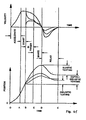
- the processor may be utilized to monitor position and speed of a penetrating member as the penetrating member moves in a first direction.
- the processor may be utilized to adjust an application of force to a penetrating member to achieve a desired speed of the penetrating member.
- the processor may be utilized to adjust an application of force to a penetrating member when the penetrating member contacts a target tissue so that the penetrating member penetrates the target tissue within a desired range of speed.
- the processor may be utilized to monitor position and speed of a penetrating member as the penetrating member moves in the first direction toward a target tissue, wherein the application of a launching force to the penetrating member is controlled based on position and speed of the penetrating member.
- the processor may be utilized to control a withdraw force to the penetrating member so that the penetrating member moves in a second direction away from the target tissue.
- the penetrating member may move toward the target tissue at a speed that is different than a speed at which the penetrating member moves away from the target tissue.
- the penetrating member may move toward the target tissue at a speed that is greater than a speed at which the penetrating member moves away from the target tissue.
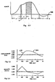
- the speed of a penetrating member in the first direction may be the range of about 2.0 to 10.0 m/sec.
- the average velocity of the penetrating member during a tissue penetration stroke in the first direction may be about 100 to about 1000 times greater than the average velocity of the penetrating member during a withdrawal stroke in a second direction.
- the present invention provides a multiple analyte detecting member solution for body fluid sampling Specifically, some embodiments of the present invention provides a multiple analyte detecting member and multiple lancet solution to measuring analyte levels in the body.
- the invention may use a high density design. It may use lancets of smaller size, such as but not limited to diameter or length, than known lancets.
- the device may be used for multiple lancing events without having to remove a disposable from the device.
- the invention may provide improved sensing capabilities. At least some of these and other objectives described herein will be met by embodiments of the present invention.
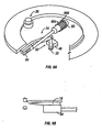
- FIGS 1-11 of the accompanying drawings illustrates one embodiment of a system 10 for piercing tissue to obtain a blood sample.
- the system 10 may include a replaceable cartridge 12 and an apparatus 14 for removably receiving the cartridge 12 and for manipulating components of the cartridge 12.
- the cartridge 12 may include a plurality of penetrating members 18.
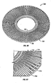
- the cartridge 12 may be in the form of a circular disc and has an outer circular surface 20 and an opening forming an inner circular surface 22.
- a plurality of grooves 24 are formed in a planar surface 26 of the cartridge 12. Each groove 24 is elongated and extends radially out from a center point of the cartridge 12. Each groove 24 is formed through the outer circular surface 20. Although not shown, it should be understood that the grooves 24 are formed over the entire circumference of the planar surface 26. As shown in Figures 3 and 4 , each groove 24 is relatively narrow closer to the center point of the cartridge 12 and slightly wider further from the center point. These grooves 24 may be molded into the cartridge 12, machined into the cartridge, forged, pressed, or formed using other methods useful in the manufacture of medical devices.
- each penetrating member 18 has an elongated body 26 and a sharpened distal end 27 having a sharp tip 30.
- the penetrating member 18 may have a circular cross-section with a diameter in this embodiment of about 0.315 mm. All outer surfaces of the penetrating member 18 may have the same coefficient of friction.
- the penetrating member may be, but is not necessarily, a bare lancet.
- the lancet is "bare", in the sense that no raised formations or molded parts are formed thereon that are complementarily engageable with another structure.
- Traditional lancets include large plastic molded parts that are used to facilitate engagement. Unfortunately, such attachments add size and cost.
- a bare lancet or bare penetrating member is an elongate wire having sharpened end. If it is of sufficiently small diameter, the tip may be penetrating without having to be sharpened.
- a bare lancet may be bent and still be considered a bare lancet.
- the bare lancet in one embodiment may be made of one material.
- each penetrating member 18 is located in a respective one of the grooves 24.
- the penetrating members 18 have their sharpened distal ends 27 pointed radially out from the center point of the cartridge 12.
- a proximal end of each penetrating member 15 may engage in an interference fit with opposing sides of a respective groove 24 as shown in Figure 3 .
- Other embodiments of the cartridge 12 may not use such an interference fit.
- they may use a fracturable adhesive to releasably secure the penetrating member 18 to the cartridge 12.
- more distal portions of the penetrating member 18 are not engaged with the opposing sides of the groove 24 due to the larger spacing between the sides.
- the cartridge 12 may further include a sterilization barrier 28 attached to the upper surface 26.
- the sterilization barrier 28 is located over the penetrating members 18 and serves to insulate the penetrating members 18 from external contaminants.
- the sterilization barrier 28 is made of a material that can easily be broken when an edge of a device applies a force thereto.
- the sterilization barrier 28 alone or in combination with other barriers may be used to create a sterile environment about at least the tip of the penetrating member prior to lancing or actuation.
- the sterilization barrier 28 may be made of a variety of materials such as but not limited to metallic foil, aluminum foil, paper, polymeric material, or laminates combining any of the above. Other details of the sterilization barrier are detailed herein.
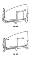
- the apparatus 14 may include a housing 30, an initiator button 32, a penetrating member movement subassembly 34, a cartridge advance subassembly 36, batteries 38, a capacitor 40, a microprocessor controller 42, and switches 44.
- the housing 30 may have a lower portion 46 and a lid 48.
- the lid 48 is secured to the lower portion 46 with a hinge 50.
- the lower portion 46 may have a recess 52.
- a circular opening 54 in the lower portion 46 defines an outer boundary of the recess 52 and a level platform 56 of the lower portion 46 defines a base of the recess 52.
- the lid 48 of the present embodiment is pivoted into a position as shown in Figure 1 .
- the cartridge 12 is flipped over and positioned in the recess 52.
- the planar surface 26 rests against the level platform 56 and the circular opening 54 contracts the outer circular surface 20 to prevent movement of the cartridge 12 in a plane thereof
- the lid 48 is then pivoted in a direction 60 and closes the cartridge 12.
- the penetrating member movement subassembly 34 includes a lever 62, a penetrating member accelerator 64, a linear actuator 66, and a spring 68.
- Other suitable actuators including but not limited to rotary actuators are described in commonly assigned, copending U.S. Patent Application Ser. No. 10/127,395 (Attorney Docket No. 38187-2551) filed April 19, 2002 ( US 2003-0083686 A1 ).
- the lever 62 may be pivotably secured to the lower portion 46.
- the button 32 is located in an accessible position external of the lower portion 46 and is connected by a shaft 70 through the lower portion 46 to one end of the lever 62.
- the penetrating member accelerator 64 is mounted to an opposing end of the lever 62.
- a user depresses the button 32 in an upward direction 66 so that the shaft 70 pivots the end of the lever 62 to which it is connected in an upward direction.
- the opposing end of the lever pivots in a downward direction 66.
- the spring 46 is positioned between the button 32 and the base 40 and compresses when the button 32 is depressed to create a force that tends to move the button 32 down and pivot the penetrating member accelerator upward in a direction opposite to the direction 64.
- the movement of the button into the position shown in Figure 5 also causes contact between a terminal 74 on the shaft 20 with a terminal 70 secured to the lower portion 46.
- Contact between the terminals 74 and 76 indicates that the button 32 has been fully depressed.
- the cartridge advancer subsystem 36 includes a pinion gear 80 and a stepper motor 82.
- the stepper motor 82 is secured to the lower portion 46.
- the pinion gear 80 is secured to the stepper motor 82 and is rotated by the stepper motor 82. Teeth on the pinion gear 80 engage with teeth on the inner circular surface 22 of the cartridge 12.
- Rotation of the pinion gear 80 causes rotation of the cartridge 12 about the center point thereof.
- the stepper motor 82 is operated to rotate the cartridge 12 through a discrete angle equal to an angular spacing from a centerline of one of the penetrating members 18 to a centerline of an adjacent penetrating member.
- a select penetrating member 18 is so moved over the penetrating member accelerator 64, as shown in Figure 6B . Subsequent depressions of the button 32 will cause rotation of subsequent adjacent penetrating members 18 into a position over the penetrating member accelerator 64.
- the force created by the spring 68 or other resilient member moves the button 32 in a downward direction 76.
- the shaft 70 is pivotably secured to the lever 62 so that the shaft 70 moves the end of the lever 62 to which it is connected down.
- the opposite end of the lever 62 pivots the penetrating member accelerator 64 upward in a direction 80.
- an edge 82 of the penetrating member accelerator 64 breaks through a portion of the sterilization barrier 28 and comes in to physical contact with a lower side surface of the penetrating member 18.
- the linear actuator 66 includes separate advancing coils 86A and retracting coils 86B, and a magnetizable slug 90 within the coils 86A and 86B.
- the coils 86A and 86B are secured to the lower portion of 46, and the slug 90 can move within the coils 86A and 88B.
- a bearing 91 is secured to the lever and the penetrating member accelerator 64 has a slot 92 over the bearing 91.
- the slot 92 allows for the movement of the penetrating member accelerator 64 in the direction 88 relative to the lever 62, so that the force created on the slug moves the penetrating member accelerator 64 in the direction 88.
- the spring 68 is not entirely relaxed, so that the spring 68, through the lever 62, biases the penetrating member accelerator 64 against the lower side surface of the penetrating member 18 with a force F1.
- the penetrating member 18 rests against a base 88 of the cartridge 12.
- An equal and opposing force F2 is created by the base 88 on an upper side surface of the penetrating member 18.
- the edge 82 of the penetrating member accelerator 64 has a much higher coefficient of friction than the base 88 of the cartridge 12.
- the higher coefficient of friction of the edge contributes to a relatively high friction force F3 on the lower side surface of the penetrating member 18.
- the relatively low coefficient of friction of the base 88 creates a relatively small friction force F4 on the upper side surface of the penetrating member 18.
- a difference between the force F3 and F4 is a resultant force that accelerates the penetrating member in the direction 88 relative to the cartridge 12.
- the penetrating member is moved out of the interference fit illustrated in Figure 3 .
- the bare penetrating member 18 is moved without the need for any engagement formations on the penetrating member.
- sterile penetrating members can so be used until all the penetrating members have been used, i.e., after one complete revolution of the cartridge 12.
- a second revolution of the cartridge 12 is disallowed to prevent the use of penetrating members that have been used in a previous revolution and have become contaminated.
- the only way in which the user can continue to use the apparatus 14 is by opening 'the lid 48 as shown in Figure 1 , removing the used cartridge 12, and replacing the used cartridge with another cartridge.
- a detector (not shown) detects whenever a cartridge is removed and replaced with another cartridge. Such a detector may be but is not limited to an optical sensor, an electrical contact sensor, a bar code reader, or the like.
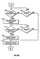
- FIG. 10 illustrates the manner in which the electrical components may be functionally interconnected for the present embodiment.
- the battery 38 provides power to the capacitor 40 and the controller 42.
- the terminal 76 is connected to the controller 42 so that the controller recognizes when the button 32 is depressed.
- the capacitor to provide power (electric potential and current) individually through the switches (such as field-effect transistors) to the advancing coils 86A, retracting coils 86B and the stepper motor 82.
- the switches 44A, B, and C are all under the control of the controller 42.
- a memory 100 is connected to the controller.
- a set of instructions is stored in the memory 100 and is readable by the controller 42. Further functioning of the controller 42 in combination with the terminal 76 and the switches 44A, B, and C should be evident from the foregoing description.
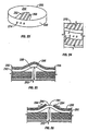
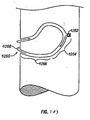
- Figure 11 illustrates a configuration for another embodiment of a cartridge having penetrating members.
- the cartridge 112 has a corrugated configuration and a plurality of penetrating members 118 in grooves 124 formed in opposing sides of the cartridge 112.
- Sterilization barriers 126 and 128 are attached over the penetrating members 118 at the top and the penetrating members 118 at the bottom, respectively.
- Such an arrangement provides large surfaces for attachment of the sterilization barriers 126 and 128. All the penetrating members 118 on the one side are used first, whereafter the cartridge 112 is turned over and the penetrating members 118 on the other side are used. Additional aspects of such a cartridge are also discussed in Figures 42-44 .
- FIG. 12 a friction based method of coupling with and driving bare lancets or bare penetrating members will be described in further detail. Any embodiment of the present invention disclosed herein may be adapted to use these methods.
- surface 201 is physically in contact with penetrating member 202.
- Surface 203 is also physically in contact with penetrating member 202.
- surface 201 is stainless steel
- penetrating member 202 is stainless steel
- surface 203 is polytetrafluoroethylene-coated stainless steel.
- Figure 13 illustrates one embodiment of the friction based coupling in use.
- Normal force 206 may be applied vertically to surface 201, pressing it against penetrating member 202. Penetrating member 202 is thereby pressed against surface 203. Normal force 206 is transmitted through surface 201 and penetrating member 202 to also act between penetrating member 202 and surface 203. Surface 203 is held rigid or stationary with respect to a target of the lancet.
- the maximum frictional force between surface 201 and penetrating member 202 is equal to the friction coefficient between surface 201 and penetrating member 202 multiplied by the normal force between surface 201 and penetrating member 202.
- the maximum frictional force between surface 203 and penetrating member 202 is equal to the coefficient of friction between the surface 203 and the penetrating member 202 multiplied by the normal force between the surface 203 and the penetrating member 202. Because friction coefficient between surface 203 and penetrating member 202 is less than friction coefficient between surface 201 and penetrating member 202, the interface between surface 201 and penetrating member 202 can develop a higher maximum static friction force than can the interface between surface 203 and penetrating member 202.
- Driving force as indicated by arrow 207 is applied to surface 201 perpendicular to normal force 206.
- the sum of the forces acting horizontally on surface 201 is the sum of driving force 207 and the friction force developed at the interface of surface 201 and penetrating member 202, which acts in opposition to driving force 207. Since the coefficient of friction between surface 203 and penetrating member 202 is less than the coefficient of friction between surface 201 and penetrating member 202, penetrating member 202 and surface 201 will remain stationary with respect to each other and can be considered to behave as one piece when driving force 207 just exceeds the maximum frictional force that can be supported by the interface between surface 203 and penetrating member 202.
- Surface 201 and penetrating member 202 can be considered one piece because the coefficient of friction between surface 201 and penetrating member 202 is high enough to prevent relative motion between the two.
- the coefficient of friction between surface 201 and penetrating member 202 is approximately 0.8 corresponding to the coefficient of friction between two surfaces of stainless steel, while the coefficient of friction between surface 203 and penetrating member 202 is approximately 0.04, corresponding to the coefficient of friction between a surface of stainless steel and one of polytetrafluoroethylene.
- Normal force 206 has a value of 202 Newtons. Using these values, the maximum frictional force that the interface between surface 201 and penetrating member 202 can support is 1.6 Newtons, while the maximum frictional force that the interface between surface 203 and penetrating member 202 can support is 0.08 Newtons.
- driving force 207 exceeds 0.08 Newtons, surface 201 and penetrating member 202 will begin to accelerate together with respect to surface 203. Likewise, if driving force 207 exceeds 1.6 Newtons and penetrating member 202 encounters a rigid barrier, surface 201 would move relative to penetrating member 202.
- penetrating member 202 has a mass of 8.24 x 10⁻⁶ kg.
- An acceleration of 194,174 m/s2 of penetrating member 202 would therefore be required to exceed the frictional force between penetrating member 202 and surface 201, corresponding to approximately 19,800 g's.
- other methods of applying friction base coupling may also be used.
- the penetrating member 202 may be engaged by a coupler using a interference fit to create the frictional engagement with the member.
- Figure 14 illustrates a polytetrafluoroethylene coating on stainless steel surface 203 in detail. It should be understood that the surface 203 may be coated with other materials such as but not limited to Telfon®, silicon, polymer or glass. The coating may cover all of the penetrating member, only the proximal portions, only the distal portions, only the tip, only some other portion, or some combination of some or all of the above.
- Figure 15 illustrates a doping of lead applied to surface 201, which conforms to penetrating member 202 microscopically when pressed against it. Both of these embodiments and other coated embodiments of a penetrating member may be used with the actuation methods described herein.
- surface 201 and surface 102 could be some form other than shown in Figures 12-15 .
- surface 201 could be the surface of a wheel, which when rotated causes penetrating member 202 to advance or retract relative to surface 203.
- Surface 201 could be coated with another conformable material besides lead, such as a plastic. It could also be coated with particles, such as diamond dust, or given a surface texture to enhance the friction coefficient of surface 201 with penetrating member 202.
- Surface 202 could be made of or coated with diamond, fluorinated ethylene propylene, perfluoroalkoxy, a copolymer of ethylene and tetrafluoroethylene, a copolymer of ethylene and chlorotrifluoroethylene, or any other material with a coefficient of friction with penetrating member 202 lower than that of the material used for surface 201.
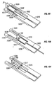
- a portion of a base plate 210 of an embodiment of a penetrating member cartridge is shown with a plurality of penetrating member slots 212 disposed in a radial direction cut into a top surface 214 of the base plate.
- a drive member 216 is shown with a distal edge 218 disposed within one of the penetrating member slots 212 of the base plate 210.
- the distal edge 218 of the drive member 216 is configured to slide within the penetrating member slots 212 with a minimum of friction but with a close fit to minimize lateral movement during a lancing cycle.
- Figure 17 shows a distal portion 220 of a coated penetrating member 222 in partial longitudinal section.
- the coated penetrating member 222 has a core portion 224, a coating 226 and a tapered distal end portion 228.
- a portion of a coated drive member 230 is shown having a coating 234 with penetrating member contact surface 236.
- the penetrating member contact surface 236 forms an interface 238 with an outer surface 240 of the coated penetrating member 222.
- the interface 238 has a characteristic friction coefficient that will depend in part on the choice of materials for the penetrating member coating 226 and the drive member coating 234.
- the penetrating member and drive member coating 226 and 236 yields a friction coefficient of about 1.3 to about 1.5.
- Other materials can be used for coatings 226 and 236 to achieve the desired friction coefficient.
- gold, platinum, stainless steel and other materials may be used for coatings 226 and 236. It may be desirable to use combinations of different materials for coatings 226 and 236.
- an embodiment may include silver for a penetrating member coating 226 and gold for a drive member coating.
- Some embodiments of the interface 238 can have friction coefficients of about 1.15 to about 5.0, specifically, about 1.3 to about 2.0.
- Embodiments of the penetrating member 222 can have an outer transverse dimension or diameter of about 200 to about 400 microns, specifically, about 275 to about 325 microns. Embodiments of penetrating member 222 can have a length of about 10 to about 30 millimeters, specifically, about 15 to about 25 millimeters. Penetrating member 222 can be made from any suitable high strength alloy such as stainless steel or the like.
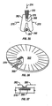
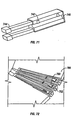
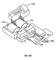
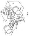
- FIG 18 is a perspective view of a lancing device 242 having features of the invention.
- a penetrating member cartridge 244 is disposed about a driver 246 that is coupled to a drive member 248 by a coupler rod 250.
- the penetrating member cartridge 244 has a plurality of penetrating member slots 252 disposed in a radial configuration in a top surface 254 a base plate 256 of the penetrating member cartridge 244.
- the distal ends 253 of the penetrating member slots 252 are disposed at an outer surface 260 of the base plate 256.
- a fracturable sterility barrier 258, shown partially cut away, is disposed on the top surface 254 of base plate 256 over the plurality of penetrating member slots 252.
- the sterility barrier 258 is also disposed over the outer surface 260 of the base plate 256 in order to seal the penetrating member slots from contamination prior to a lancing cycle.
- a distal portion of a penetrating member 262 is shown extending radially from the penetrating member cartridge 244 in the direction of a patient's finger 264.
- Figure 19 illustrates a portion of the base plate 256 used with the lancing device 242 in more detail and without sterility barrier 258 in place (for ease of illustration).
- the base plate 256 includes a plurality of penetrating member slots 252 which are in radial alignment with corresponding drive member slots 266.
- the drive member slots 266 have an optional tapered input configuration that may facilitate alignment of the drive member 248 during downward movement into the drive member slot 266 and penetrating member slot 252.
- Penetrating member slots 252 are sized and configured to accept a penetrating member 262 disposed therein and allow axial movement of the penetrating member 262 within the penetrating member slots 252 without substantial lateral movement.
- penetrating member cartridge 242 is placed in an operational configuration with the driver 246.
- a lancing cycle is initiated and the drive member 248 is brought down through the sterility barrier 258 and into a penetrating member slot 252.
- a penetrating member contact surface of the drive member then makes contact with an outside surface of the penetrating member 262 and is driven distally toward the patient's finger 264 as described above with regard to the embodiment discussed in Figure 20 .
- the friction coefficient between the penetrating member contact surface of the drive member 248 and the penetrating member 262 is greater than the friction coefficient between the penetrating member 262 and an interior surface of the penetrating member slots 252.
- the drive member 248 is able to drive the penetrating member 262 distally through the sterility barrier 258 and into the patient's finger 264 without any relative movement or substantial relative movement between the drive member 248 and the penetrating member 262.
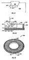
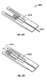
- a lancing cycle sequence is shown for a lancing device 242 with another embodiment of a penetrating member cartridge 244 as shown in Figures 23 and 24 .
- the base plate 256 of the penetrating member cartridge 242 shown in Figures 23 and 24 has a plurality of penetrating member slots 252 with top openings 268 that do not extend radially to the outer surface 260 of the base plate 256.
- the penetrating member slots 252 can be sealed with a first sterility barrier 270 disposed on the top surface 254 of the base plate 256 and a second sterility barrier 272 disposed on the outer surface 260 of the base plate 256.
- Penetrating member outlet ports 274 are disposed at the distal ends of the penetrating member slots 252.
- the penetrating member 262 is shown in the proximally retracted starting position within the penetrating member slot 252.
- the outer surface of the penetrating member 276 is in contact with the penetrating member contact surface 278 of the drive member 248.
- the friction coefficient between the penetrating member contact surface 278 of the drive member 248 and the outer surface 276 of the penetrating member 262 is greater than the friction coefficient between the penetrating member 262 and an interior surface 280 of the penetrating member slots 252.
- a distal drive force as indicated by arrow 282 in Figure 10 is then applied via the drive coupler 250 to the drive member 248 and the penetrating member is driven out of the penetrating member outlet port 274 and into the patient's finger 264.
- a proximal retraction force is then applied to the drive member 248 and the penetrating member 262 is withdrawn from the patient's finger 264 and back into the penetrating member slot 252.
- Figures 25 and 26 illustrate an embodiment of a multiple layer sterility barrier 258 in the process of being penetrated by a penetrating member 62. It should be understood that this barrier 258 may be adapted for use with any embodiment of the present invention.
- the sterility barrier 258 shown in Figures 25 and 26 is a two layer sterility barrier 258 that facilitates maintaining sterility of the penetrating member 262 as it passes through and exits the sterility barrier 258.
- the distal end 286 of the penetrating member 262 is applying an axial force in a distal direction against an inside surface 288 of a first layer 290 of the sterility barrier 258, so as to deform the first layer 290 of the sterility barrier 258.
- the deformation 291 of the first layer 290 in turn applies a distorting force to the second layer 292 of the sterility barrier 258.
- the second layer of the sterility barrier is configured to have a lower tensile strength that the first layer 290.
- the second layer 292 fails prior to the first layer 290 due to the strain imposed on the first layer 290 by the distal end 286 of the penetrating member 262, as shown in Figure 26 .
- Such a multiple layer sterility barrier 258 can be used for any of the embodiments discussed herein.
- the multiple layer sterility barrier 258 can also include three or more layers.
- a drive member 300 coupled to a driver 302 wherein the drive member 300 includes a cutting member 304 having a sharpened edge 306 which is configured to cut through a sterility barrier 258 of a penetrating member slot 252 during a lancing cycle in order for the drive member 300 to make contact with a penetrating member.
- An optional lock pin 308 on the cutting member 304 can be configured to engage the top surface 310 of the base plate in order to prevent distal movement of the cutting member 304 with the drive member 300 during a lancing cycle.
- Figures 29 and 30 illustrate an embodiment of a penetrating member slot 316 in longitudinal section having a ramped portion 318 disposed at a distal end 320 of the penetrating member slot.
- a drive member 322 is shown partially disposed within the penetrating member slot 316.
- the drive member 322 has a cutting edge 324 at a distal end 326 thereof for cutting through a sterility barrier 328 during a lancing cycle.
- Figure 30 illustrates the cutting edge 324 cutting through the sterility barrier 328 during a lancing cycle with the cut sterility barrier 328 peeling away from the cutting edge 324.
- Figures 31-34 illustrate drive member slots in a base plate 330 of a penetrating member cartridge wherein at least a portion of the drive member slots have a tapered opening which is larger in transverse dimension at a top surface of the base plate than at the bottom of the drive member slot.
- Figure 31 illustrates a base plate 330 with a penetrating member slot 332 that is tapered at the input 334 at the top surface 336 of the base plate 330 along the entire length of the penetrating member slot 332.
- the penetrating member slot and drive member slot would be in communication and continuous along the entire length of the slot 332.
- a base plate 338 as shown in Figure 32 and 33 can have a drive member slot 340 that is axially separated from the corresponding penetrating member slot 342.
- the drive member slot 340 can have a tapered configuration and the penetrating member slot 342 can have a straight walled configuration.
- this configuration can be used for corrugated embodiments of base plates 346 as shown in Figure 34 .
- a drive member 348 is disposed within a drive member slot 350.
- a penetrating member contact surface 352 is disposed on the drive member 348. The contact surface 352 has a tapered configuration that will facilitate lateral alignment of the drive member 348 with the drive member slot 350.
- Figures 35-37 illustrate an embodiment of a penetrating member cartridge 360 and drive member 362 wherein the drive member 362 has contoured jaws 364 configured to grip a penetrating member shaft 366.
- the drive member 362 and penetrating member shaft 366 are shown in transverse cross section with the contoured jaws 364 disposed about the penetrating member shaft 366.
- a pivot point 368 is disposed between the contoured jaws 364 and a tapered compression slot 370 in the drive member 362.
- a compression wedge 372 is shown disposed within the tapered compression slot 370. Insertion of the compression wedge 372 into the compression slot 370 as indicated by arrow 374, forces the contoured jaws 364 to close about and grip the penetrating member shaft 366 as indicated by arrows 376.
- Figure-36 shows the drive member 362 in position about a penetrating member shaft 366 in a penetrating member slot 378 in the penetrating member cartridge 360.
- the drive member can be actuated by the methods discussed above with regard to other drive member and driver embodiments.
- Figure 37 is an elevational view in longitudinal section of the penetrating member shaft 166 disposed within the penetrating member slot 378.
- the arrows 380 and 382 indicate in a general way, the path followed by the drive member 362 during a lancing cycle.
- the drive member comes down into the penetrating member slot 378 as indicated by arrow 380 through an optional sterility barrier (not shown).
- the contoured jaws of the drive member then clamp about the penetrating member shaft 366 and move forward in a distal direction so as to drive the penetrating member into the skin of a patient as indicated by arrow 382.
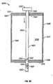
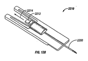
- Figures 38 and 39 show a portion of a lancing device 390 having a lid 392 that can be opened to expose a penetrating member cartridge cavity 394 for removal of a used penetrating member cartridge 396 and insertion of a new penetrating member cartridge 398.
- Depression of button 400 in the direction indicated by arrow 402 raises the drive member 404 from the surface of the penetrating member cartridge 396 by virtue of lever action about pivot point 406. Raising the lid 392 actuates the lever arm 408 in the direction indicated by arrow 410 which in turn applies a tensile force to cable 412 in the direction indicated by arrow 414.
- This action pulls the drive member back away from the penetrating member cartridge 396 so that the penetrating member cartridge 396 can be removed from the lancing device 390.
- a new penetrating member cartridge 398 can then be inserted into the lancing device 390 and the steps above reversed in order to position the drive member 404 above the penetrating member cartridge 398 in an operational position.
- Figures 40 and 41 illustrate a penetrating member cartridge 420 that has penetrating member slots 422 on a top side 424 and a bottom side 426 of the penetrating member cartridge 420. This allows for a penetrating member cartridge 420 of a diameter D to store for use twice the number of penetrating members as a one sided penetrating member cartridge of the same diameter D.
- Figures 42-44 illustrate end and perspective views of a penetrating member cartridge 430 having a plurality of penetrating member slots 432 formed from a corrugated surface 434 of the penetrating member cartridge 430.
- Penetrating members 436 are disposed on both sides of the penetrating member cartridge 430.
- a sterility barrier 438 is shown disposed over the penetrating member slots 432 in Figure 44 .
- Figures 45-48 illustrate embodiments of a penetrating member 440 and drive member 442 wherein the penetrating member 440 has a transverse slot 444 in the penetrating member shaft 446 and the drive member 442 has a protuberance 448 configured to mate with the transverse slot 444 in the penetrating member shaft 446.
- Figure 45 shows a protuberance 448 having a tapered configuration that matches a tapered configuration of the transverse slot 444 in the penetrating member shaft 446.
- Figure 46 illustrates an optional alternative embodiment wherein the protuberance 448 has straight walled sides that are configured to match the straight walled sides of the transverse slot 444 shown in Figure 46 .
- Figure 47 shows a tapered protuberance 448 that is configured to leave an end gap 450 between an end of the protuberance 448 and a bottom of the transverse slot in the penetrating member shaft 446.
- Figure 48 illustrates a mechanism 452 to lock the drive member 442 to the penetrating member shaft 446 that has a lever arm 454 with an optional bearing 456 on the first end 458 thereof disposed within a guide slot 459 of the drive member 442.
- the lever arm 454 has a pivot point 460 disposed between the first end 458 of the lever arm 454 and the second end 462 of the lever arm 454.
- a biasing force is disposed on the second end 462 of the lever arm 454 by a spring member 464 that is disposed between the second end 462 of the lever arm 454 and a base plate 466.
- the biasing force in the direction indicated by arrow 468 forces the penetrating member contact surface 470 of the drive member 442 against the outside surface of the penetrating member 446 and, in addition, forces the protuberance 448 of the drive member 442 into the transverse slot 444 of the penetrating member shaft 446.
- cartridge 500 suitable for housing a plurality of individually moveable penetrating members (not shown) will be described in further detail.
- cartridge 500 is shown with a chamfered outer periphery, it should also be understood that less chamfered and unchamfered embodiments of the cartridge 500 may also be adapted for use with any embodiment of the present invention disclosed herein.
- the penetrating members slidably coupled to the cartridge may be a bare lancet or bare elongate member without outer molded part or body pieces as seen in conventional lancet. The bare design reduces cost and simplifies manufacturing of penetrating members for use with the present invention.
- the penetrating members may be retractable and held within the cartridge so that they are not able to be used again.
- the cartridge is replaceable with a new cartridge once all the piercing members have been used.
- the lancets or penetrating members may be fully contained in the used cartridge so at to minimize the chance of patient contact with such waste.
- the cartridge 500 may include a plurality of cavities 501 for housing a penetrating member.
- the cavity 501 may have a longitudinal opening 502 associated with the cavity.
- the cavity 501 may also have a lateral opening 503 allowing the penetrating member to exit radially outward from the cartridge.
- the outer radial portion of the cavity may be narrowed.
- the upper portion of this narrowed area may also be sealed or swaged to close the top portion 505 and define an enclosed opening 506 as shown in Figure 50 .
- the narrowed area 504 may retain an open top configuration, though in some embodiments, the foil over the gap is unbroken, preventing the penetrating member from lifting up or extending upward out of the cartridge.
- the narrowed portion 504 may act as a bearing and/or guide for the penetrating member.
- Figure 51 shows that the opening 506 may have a variety of shapes such as but not limited to, circular, rectangular, triangular, hexagonal, square, or combinations of any or all of the previous shapes. Openings 507 (shown in phantom) for other microfluidics, capillary tubes, or the like may also be incorporated in the immediate vicinity of the opening 506. In some optional embodiments, such openings 507 may be configured to surround the opening 506 in a concentric or other manner.
- FIG. 52 the underside of a cartridge 500 will be described in further detail.
- This figures shows many features on one cartridge 500. It should be understood that a cartridge may include some, none, or all of these features, but they are shown in Figure 52 for ease of illustration.
- the underside may include indentations or holes 510 close to the inner periphery for purpose of properly positioning the cartridge to engage a penetrating member gripper and/or to allow an advancing device (shown in Figure 56B and 56C ) to rotate the cartridge 500.
- Indentations or holes 511 may be formed along various locations on the underside of cartridge 500 and may assume various shapes such as but not limited to, circular, rectangular, triangular, hexagonal, square, or combinations of any or all of the previous shapes.
- Notches 512 may also be formed along the inner surface of the cartridge 500 to assist in alignment and/or rotation of the cartridge. It should be understood of course that some of these features may also be placed on the topside of the cartridge in areas not occupied by cavities 501 that house the penetrating members. Notches 513 may also be incorporated along the outer periphery of the cartridge. These notches 513 may be used to gather excess material from the sterility barrier 28 (not shown) that may be used to cover the angled portion 514 of the cartridge.
- the cartridge has a flat top surface and an angled surface around the outside. Welding a foil type sterility barrier over that angled surface, the foil folds because of the change in the surfaces which is now at 45 degrees. This creates excess material.
- the grooves or notches 513 are there as a location for that excess material. Placing the foil down into those grooves 513 which may tightly stretch the material across the 45 degree angled surface.
- the surface is shown to be at 45 degrees, it should be understood that other angles may also be used.
- the surface may be at any angle between about 3 degrees to 90 degrees, relative to horizontal.
- the surface may be squared off.
- the surface may be unchamfered.
- the surface may also be a curved surface or it may be combinations of a variety of angled surfaces, curved and straights surfaces, or any combination of some or all of the above.
- each cavity on the cartridge maybe individually sealed with a foil cover or other sterile enclosure material to maintain sterility until or just before the time of use.
- penetrating members are released from their sterile environments just prior to actuation and are loaded onto a launcher mechanism for use. Releasing the penetrating member from the sterile environment prior to launch allows the penetrating member in the present embodiment to be actuated without having to pierce any sterile enclosure material which may dull the tip of the penetrating member or place contaminants on the member as it travels towards a target tissue. A variety of methods may be used accomplish this goal.
- Figure 53A shows one embodiment of penetrating member release device, which in this embodiment is a punch plate 520 that is shown in a see-through depiction for ease of illustration.
- the punch plate 520 may include a first portion 521 for piercing sterile material covering the longitudinal opening 502 and a second portion 522 for piercing material covering the lateral opening 503.
- a slot 523 allows the penetrating member gripper to pass through the punch plate 520 and engage a penetrating member housed in the cartridge 500.
- the second portion 522 of the punch plate down to engage sterility barrier angled at about a 45 degree slope. Of course, the slope of the barrier may be varied.
- the punch portion 522 first contacts the rear of the front pocket sterility barrier and as it goes down, the cracks runs down each side and the barrier is pressed down to the bottom of the front cavity.
- the rear edge of the barrier first contacted by the punch portion 522 is broken off and the barrier is pressed down, substantially cleared out of the way.
- the punch portion 521 may include a blade portion down the centerline. As the punch comes down, that blade may be aligned with the center of the cavity, cutting the sterility barrier into two pieces. The wider part of the punch 521 then pushes down on the barrier so the they align parallel to the sides of the cavity. This creates a complete and clear path for the gripper throughout the longitudinal opening of the cavity.
- a plurality of protrusion 524 are positioned to engage a cam ( Figure 55A ) which sequences the punching and other vertical movement of punch plate 520 and cartridge pusher 525.
- the drive shaft 526 from a force generator (not shown) which is used to actuate the penetrating member 527.
- Figure 54A shows the release and loading mechanism in rest state with a dirty bare penetrating member 527 held in a penetrating member gripper 530. This is the condition of the device between lancing events.
- the patient begins the loading of a new penetrating member by operating a setting lever to initiate the process.
- the setting lever may operate mechanically to rotate a cam (see Figure 55A ) that moves the punch plate 520 and cartridge pusher 525.
- a stepper motor or other mover such as but not limited to, a pneumatic actuator, hydraulic actuator, or the like are used to drive the loading sequence.
- FIG 54B shows one embodiment of penetrating member gripper 530 in more detail.
- the penetrating member gripper 530 may be in the form of a tuning fork with sharp edges along the inside of the legs contacting the penetrating member.
- the penetrating member may be notched, recessed, or otherwise shaped to receive the penetrating member gripper.
- the legs are spread open elastically to create a frictional grip with the penetrating member such as but not limited to bare elongate wires without attachments molded or otherwise attached thereon.
- the penetrating member is made of a homogenous material without any additional attachments that are molded, adhered, glued or otherwise added onto the penetrating member.
- the gripper 530 may cut into the sides of the penetrating member.
- the penetrating member in one embodiment may be about 300 microns wide.
- the grooves that form in the side of the penetrating member by the knife edges are on the order of about 5-10 microns deep and are quite small.
- the knife edges allow the apparatus to use a small insertion force to get the gripper onto the penetrating member, compared to the force to remove the penetrating member from the gripper the longitudinal axis of an elongate penetrating member. Thus, the risk of a penetrating member being detached during actuation are reduced.
- the gripper 530 may be made of a variety of materials such as, but not limited to high strength carbon steel that is heat treated to increased hardness, ceramic, substrates with diamond coating, composite reinforced plastic, elastomer, polymer, and sintered metals. Additionally, the steel may be surface treated.
- the gripper 130 may have high gripping force with low friction drag on solenoid or other driver.
- the sequence begins with punch plate 520 being pushed down. This results in the opening of the next sterile cavity 532. In some embodiment, this movement of punch plate 520 may also result in the crimping of the dirty penetrating member to prevent it from being used again. This crimping may result from a protrusion on the punch plate bending the penetrating member or pushing the penetrating member into a groove in the cartridge that hold the penetrating member in place through an interference fit. As seen in Figures 53B and 54C , the punch plate 520 has a protrusion or punch shaped to penetrate a longitudinal opening 502 and a lateral opening 503 on the cartridge.
- the first portion 521 of the punch that opens cavity 532 is shaped to first pierce the sterility barrier and then push, compresses, or otherwise moves sterile enclosure material towards the sides of the longitudinal opening 502.
- the second portion 522 of the punch pushes down the sterility barrier at lateral opening or penetrating member exit 503 such that the penetrating member does not pierce any materials when it is actuated toward a tissue site.
- the cartridge pusher 525 is engaged by the cam 550 (not shown) and begins to push down on the cartridge 500.
- the punch plate 520 may also travel downward with the cartridge 500 until it is pushed down to it maximum downward position, while the penetrating member gripper 530 remains vertically stationary. This joint downward motion away from the penetrating member gripper 530 will remove the penetrating member from the gripper.
- the punch plate 520 essentially pushes against the penetrating member with protrusion 534 ( Figure 55A ), holding the penetrating member with the cartridge, while the cartridge 500 and the punch plate 520 is lowered away from the penetrating member gripper 530 which in this embodiment remains vertically stationary. This causes the stripping of the used penetrating member from the gripper 530 ( Figure 45D) as the cartridge moves relative to the gripper.
- the punch plate 520 retracts upward and the cartridge 500 is pushed fully down, clear of the gripper 530. Now cleared of obstructions and in a rotatable position, the cartridge 500 increments one pocket or cavity in the direction that brings the newly released, sterile penetrating member in cavity 532 into alignment with the penetrating member gripper 530, as see in Figure 54F .
- the rotation of the cartridge occurs due to fingers engaging the holes or indentations 533 on the cartridge, as seen in Figure 54A . In some embodiments, these indentations 533 do not pass completely through cartridge 500. In other embodiments, these indentations are holes passing completely through.
- the cartridge has a plurality of little indentations 533 on the top surface near the center of the cartridge, along the inside diameter.
- the sterility barrier is cut short so as not to cover these plurality of indentations 533. It should be understood of course that these holes may be located on bottom, side or other accessible surface.
- These indentations 533 have two purposes.
- the apparatus may have one or a plurality of locator pins, static pins, or other keying feature that dos not move.
- the cartridge will only set down into positions where the gripper 530 is gripping the penetrating member. To index the cassette, the cartridge is lifted off those pins or other keyed feature, rotated around, and dropped onto those pins for the next position.
- the rotating device is through the use of two fingers: one is a static pawl and the other one is a sliding finger. They engage with the holes 533.
- the fingers are driven by a slider that may be automatically actuated or actuated by the user. This may be occur mechanically or through electric or other powered devices. Halfway through the stroke, a finger may engage and rotate around the cartridge.
- the cartridge 500 is released as indicated by arrows 540 and brought back into contact with the penetrating member gripper 530.
- the new penetrating member 541 is inserted into the gripper 530, and the apparatus is ready to fire once again.
- the bare lancet or penetrating member 541 is held in place by gripper 530, preventing the penetrating member from accidentally protruding or sliding out of the cartridge 500.
- the penetrating member 541 may be placed in a parked position in the cartridge 500 prior to launch.
- the penetrating member is held by a narrowed portion 542 of the cartridge, creating an interference fit which pinches the proximal end of the penetrating member. Friction from the molding or cartridge holds the penetrating member during rest, preventing the penetrating member from sliding back and forth. Of course, other methods of holding the penetrating member may also be used.
- the penetrating member gripper 530 may pull the penetrating member 541 out of the portion 542.
- the penetrating member 541 may remain in this portion until actuated by the solenoid or other force generator coupled to the penetrating member gripper.
- a cam surface 544 may be used to pull the penetrating member out of the portion 542.
- This mechanical cam surface may be coupled to the mechanical slider driven by the patient, which may be considered a separate force generator.
- the penetrating member may be moved forward a small distance (on the order of about 1 mm or less) from its parked position to pull the penetrating member from the rest position gripper.
- the penetrating member may be returned to the cartridge and eventually placed into the parked position. This may also occur, though not necessarily, through force provided by the patient. In one embodiment, the placing of the lancet into the parked position does not occur until the process for loading a new penetrating member is initiated by the patient. In other embodiments, the pulling out of the parked position occurs in the same motion as the penetrating member actuation. The return into the parked position may also be considered a continuous motion.
- Figure 55A also shows one embodiment of the cam and other surfaces used to coordinate the motion of the punch plate 520.
- cam 550 in this embodiment is circular and engages the protrusions 524 on the punch plate 520 and the cartridge pusher 525.
- Figure 55A also more clearly shows protrusion 534 which helps to hold the penetrating member in the cartridge 500 while the penetrating member gripper 530 pulls away from the member, relatively speaking.
- a ratchet surface 552 that rotates with the cam 550 may be used to prevent the cam from rotating backwards.
- the raising and lower of cartridge 500 and punch plate 50 used to load/unload penetrating members may be mechanically actuated by a variety of cam surfaces, springs, or the like as may be determined by one skilled in the art.
- Some embodiments may also use electrical or magnetic device to perform the loading, unloading, and release of bare penetrating members.
- the punch plate 520 is shown to be punching downward to displace, remove, or move the foil or other sterile environment enclosure, it should be understood that other methods such as stripping, pulling, tearing, or some combination of one or more of these methods may be used to remove the foil or sterile enclosure.
- the punch plate 520 may be located on an underside of the cartridge and punch upward.
- the cartridge may remain vertically stationary while other parts such as the penetrating member gripper and punch plate move to load a sterile penetrating member on to the penetrating member gripper.
- Figure 55B also shows other features that may be included in the present apparatus.
- a fire button 560 may be included for the user to actuate the penetrating member.
- a front end interface 561 may be included to allow a patient to seat their finger or other target tissue for lancing. The interface 561 may be removable to be cleaned or replaced.
- a visual display 562 may be included to show device status, lancing performance, error reports, or the like to the patient.
- a mechanical slider 564 used by the patient to load new penetrating member may also be incorporated on the housing.
- the slider 564 may also be coupled to activate an LCD or visual display on the lancing apparatus.
- the slider 564 may also switch the electronics to start the display. The user may use the display to select the depth of lancing or other feature. The display may go back to sleep again until it is activated again by motion of the slider 564.
- the underside the housing 566 may also be hinged or otherwise removable to allow the insertion of cartridge 500 into the device.
- the cartridge 500 may be inserted using technology current used for insertion of a compact disc or other disc into a compact disc player.
- a tray which is deployed outward to receive or to remove a cartridge.
- the tray may be withdrawn into the apparatus where it may be elevated, lowered, or otherwise transported into position for use with the penetrating member driver.
- the apparatus may have a slot into which the cartridge is partially inserted at which point a mechanical apparatus will assist in completing insertion of the cartridge and load the cartridge into proper position inside the apparatus.
- Such device is akin to the type of compact disc player found on automobiles.
- the insertions/ejection and loading apparatus of these compact disc players uses gears, pulleys, cables, trays, and/or other parts that may be adapted for use with the present invention.
- the slider 564 will move initially as indicated by arrow 567. To complete the cycle, the patient will return the slider to its home position or original starting position as indicated by arrow 568.
- the slider 564 has an arm 569 which moves with the slider to rotate the cam 550 and engage portions 522.
- the motion of the slider 564 is also mechanically coupled to a finger 570 which engage the indentations 571 on cartridge 500.
- the finger 570 is synchronized to rotate the cartridge 500 by pulling as indicated by arrow 572 in the same plane as the cartridge. It should be understood that in some-embodiments, the finger 570 pushes instead of pulls to rotate the cartridge in the correct direction.
- the finger 570 may also be adapted to engage ratchet surfaces 706 as seen in Figure 66 to rotate a cartridge.
- the finger 570 may also incorporate vertical motion to coordinate with the rising and lowering of the cartridge 500.
- the motion of finger 570 may also be powered by electric actuators such as a stepper motor or other device useful for achieving motion.
- Figure 56B also shows a portion of the encoder 573 used in position sensing.
- FIG. 56C a still further view of the slider 564 and arm 569 is shown.
- the arm 569 moves to engage portion 522 as indicated by arrow 575 and this causes the cam 550 to rotate as indicated by arrow 577.
- the cam 550 rotates about 1/8 of an rotation with each pull of the slider 564.
- the arm 569 rides over the portion 522.
- the movement of the slider also allows the cam surface 544 to rotate about pivot point 579.
- a resilient member 580 may be coupled to the cam surface 544 to cause it to rotate counterclockwise when the arm 569 moves in the direction of arrow 567.
- the pin 580 will remain in contact with the arm 569.
- the cam surface 544 rotates a first surface 582 will contact the pin 583 on the gripper block 584 and pull the pin 583 back to park a penetrating member into a coupling or narrowed portion 542 of the cartridge 500 as seen in Figure 55A .
- the cam surface 544 rotates back and a second surface 586 that rotates clockwise and pushes the penetrating member forward to be released from the narrowed portion 542 resulting in a position as seen in Figure 55B .
- the release and/or parking of lancet from portion 542 may be powered by the driver 588 without using the mechanical assistance from cam surface 544.
- a mechanical feature may be included on the cartridge so that there is only one way to load it into the apparatus.
- the cartridge may have 51 pockets or cavities. The 51 st pocket will go into the firing position when the device is loaded, thus providing a location for the gripper to rest in the cartridge without releasing a penetrating member from a sterile environment.
- the gripper 530 in that zeroth position is inside the pocket or cavity and that is the reason why one of the pockets may be empty.
- some embodiments may have the gripper 530 positioned to grip a penetrating member as the cartridge 500 is loaded into the device, with the patient lancing themselves soon afterwards so that the penetrating member is not contaminated due to prolonged exposure outside the sterile enclosure. That zeroth position may be the start and finish position.
- the cartridge may also be notched to engaged a protrusion on the apparatus, thus also providing a method for allowing the penetrating member to loaded or unloaded only in one orientation.
- the cartridge 500 may be keyed or slotted in association with the apparatus so that the cartridge 500 can only be inserted or removed at one orientation.
- the cartridge 592 may have a keyed slot 593 that matches the outline of a protrusion 594 such that the cartridge 592 may only be removed upon alignment of the slot 593 and protrusion 594 upon at the start or end positions.
- the slot or key may be located on an outer periphery or other location on the cartridge 592 in manner useful for allowing insertion or removal of the cartridge from only one or a select number of orientations.
- the cavity 600 may include a depression 602 for allowing the gripper 530 to penetrate sufficiently deeply into the cavity to frictionally engage the penetrating member 541.
- the penetrating member may also be housed in a groove 604 that holds the penetrating member in place prior to and after actuation. The penetrating member 541 is lifted upward to clear the groove 604 during actuation and exits through opening 506.
- Figure 58 shows a lancing system 610 wherein the penetrating members have their sharpened tip pointed radially inward.
- the finger or other tissue of the patient is inserted through the center hole 611 to be pierced by the member 612.
- the penetrating member gripper 530 coupled to drive force generator 613 operate in substantially the same manner as described in Figures 54A-G .
- the punch portions 521 and 522 operate in substantially the same manner to release the penetrating members from the sterile enclosures.
- the punch portion 522 may be placed on the inner periphery of the device, where the penetrating member exit is now located, so that sterile enclosure material is cleared out of the path of the penetrating member exit.
- the penetrating member gripper 530 approaches the penetrating member from above and at least a portion of the drive system is located in a different plane from that of the cartridge 500.
- Figure 59 shows an embodiment where the penetrating member driver 620 is in substantially the same plane as the penetrating member 622.
- the coupler 624 engages a bent or L shaped portion 626 of the member 622.
- the cartridge 628 can rotate to engage a new penetrating member with the coupler 624 without having to move the cartridge or coupler vertically.
- the next penetrating member rotates into position in the slot provided by the coupler 624.
- a narrowed portion of the cartridge acts as a penetrating member guide 630 near the distal end of the penetrating member to align the penetrating member as it exits the cartridge.
- the coupler 624 may come in a variety of configurations.
- Figure 60A shows a coupler 632 which can engage a penetrating member 633 that does not have a bent or L-shaped portion. A radial cartridge carrying such a penetrating member 633 may rotate to slide penetrating member into the groove 634 of the coupler 632.
- Figure 60B is a front view showing that the coupler 632 may include a tapered portion 636 to guide the penetrating member 633 into the slot 634.
- Figure 60C shows an embodiment of the driver 620 using a coupler 637 having a slot 638 for receiving a T-shaped penetrating member.
- the coupler 637 may further include a protrusion 639 that may be guided in an overhead slot to maintain alignment of the drive shaft during actuation.
- a cartridge 640 for use with an in-plane driver 620 is shown.
- the cartridge 640 includes an empty slot 642 that allows the cartridge to be placed in position with the driver 620.
- the empty slot 642 allows the coupler 644 to be positioned to engage an unused penetrating member 645 that may be rotated into position as shown by arrow 646.
- the cartridge 640 may also be designed so that only the portion of the penetrating member that needs to remain sterile (i.e. the portions that may actually be penetrating into tissue) are enclosed.
- a proximal portion 647 of the penetrating member is exposed.
- the cartridge 640 may further include, but not necessarily, sealing protrusions 648. These protrusions 648 are releasably coupled to the cartridge 640 and are removed from the cartridge 640 by remover 649 as the cartridge rotates to place penetrating member 645 into the position of the active penetrating member. The sterile environment is broken prior to actuation of the member 645 and the member does not penetrate sterile enclosure material that may dull the tip of the penetrating member during actuation. A fracturable seal material 650 may be applied to the member to seal against an inner peripheral portion of the cartridge.
- This cartridge 652 includes a tapered portion 654 for allowing the coupler 655 to enter the cavity 656.
- a narrowed portion 657 guides the penetrating member 658.
- the coupler 655 may have, but does not necessarily have, movable jaws 659 that engage to grip the penetrating member 658. Allowing the coupler to enter the cavity 656 allows the alignment of the penetrating member to be better maintained during actuation.
- This tapered portion 654 may be adapted for use with any embodiment of the cartridge disclosed herein.
- FIG 63 a linear cartridge 660 for use with the present invention will be described.
- the lancing system may be adapted for use with cartridges of other shapes.
- Figures 79-83 show other cartridges of varying shapes adaptable for use with the present invention.
- Figure 63 illustrates a cartridge 660 with only a portion 662 providing sterile protection for the penetrating members.
- the cartridge 660 provides a base 664 on which a penetrating member 665 can rest. This provides a level of protection of the penetrating member during handling.
- the base 664 may also be shaped to provide slots 666 in which a penetrating member 667 may be held.
- the slot 666 may also be adapted to have a tapered portion 668.
- Figure 64A shows a rotating punch device 670 that has protrusions 672 that punch out the sterility barrier creating openings 674 from which a penetrating member can exit without touching the sterility barrier material.
- Figure 64B shows a vertically rotating device 676 with shaped protrusions 678 that punch down the sterility barrier 679 as it is rotated to be in the active, firing position.
- Figure 64C shows a punch 680 which is positioned to punch out barrier 682 when the cartridge is lowered onto the punch. The cartridge is rotated and the punch 680 rotates with the cartridge. After the cartridge is rotated to the proper position and lifted up, the punch 680 is spring loaded or otherwise configured to return to the position to engage the sterility barrier covering the next unused penetrating member.
- FIG. 65A-65B another type of punch mechanism for use with a punch plate 520 will now be described.
- the device shown in Figures 53-54 shows a mechanism that first punches and then rotates or indexes the released penetrating member into position.
- the cartridge is rotated first and then the gripper and punch may move down simultaneously.
- Figure 65A shows a punch 685 having a first portion 686 and a second portion 687.
- the penetrating member gripper 690 is located inside the punch 685.
- the penetrating of the sterility barrier is integrated into the step of engaging the penetrating member with the gripper 690.
- the punch 685 may include a slot 692 allowing a portion 694 of the gripper 690 to extend upward.
- a lateral opening 695 is provided from which a penetrating member may exit.
- the punch portion 687 is not included with punch 686, instead relying on some other mechanism such as those shown in Figures 64A-64C to press down on barrier material covering a lateral opening 503.
- Figure 66 shows a cartridge 700 with a plurality of cavities 702 and individual deflectable portions or fingers 704.
- the ends of the protective cavities 702 may be divided into individual fingers (such as one for each cavity) on the outer periphery of the disc.
- Each finger 704 may be individually sealed with a foil cover (not shown for ease of illustration) to maintain sterility until the time of use.
- a foil cover (not shown for ease of illustration) to maintain sterility until the time of use.
- a foil cover not shown for ease of illustration
- a penetrating member 708 may be housed in each cavity. The penetrating member may rest on a raised portion 710.
- Each cavity may include a wall portion 714 into which the penetrating member 708 may be driven after the penetrating member has been used.
- Figure 68 shows the penetrating member gripper 716 lowered to engage a penetrating member 708. For ease of illustration, a sterility barrier covering each of the cavities is not shown.
- the last penetrating member to be used may be left in a retracted position, captured by a gripper 716.
- the end of the protective cavity 704 may be deflected downward by the previous actuation.
- the user may operate a mechanism such as but not limited to a thumbwheel, lever, crank, slider, etc...that advances a new penetrating member 720 into launch position as seen in Figure 69A .
- the mechanism lifts a bar that allows the protective cavity to return to its original position in the plane of the disc.
- the penetrating member guide 722 presses through foil in rear of pocket to "home" penetrating member and control vertical clearance.
- actuation devices for moving the penetrating member guide 722 and other mechanisms are not shown. They may be springs, cams, or other devices that can lower and move the components shown in these figures.
- the cartridge 700 may be raised or lowered to engage the penetrating member guide 722 and other devices.
- the plough or sterile enclosure release device 724 is lowered to engage the cartridge 700.
- the disc or cartridge 700 may raised part way upward until a plough or plow blade 724 pierces the sterility barrier 726 which may be a foil covering.
- the plough 724 clears foil from front of pocket and leaves it attached to cartridge 700.
- the plough 724 is driven radially inward, cutting open the sterility barrier and rolling the scrap into a coil ahead of the plough. Foil naturally curls over and forms tight coil when plough lead angle is around 55degs to horizontal. If angle of the plough may be between about 60-40degs, preferably closer to 55 degs.
- the foil may be removed in such a manner that the penetrating member does not need to pierce any sterile enclosure materials during launch.
- the gripper 716 may be lowered to engage the bare penetrating member or piercing member 720.
- the disc or cartridge 8000 may be raised until the penetrating member 720 is pressed firmly into the gripper 716.
- the penetrating member driver or actuator of the present embodiment may remain in the same horizontal plane as the penetrating member.
- a bar 730 maybe pressed downward on the outer end 732 of the protective cavity to deflect it so it is clear of the path of the penetrating member.
- the bar 730 is shaped to allow the bare penetrating member 720 to pass through. It should be understood that other shapes and orientations of the bar (such as contacting only one side or part of end 732) may be used to engage the end 732.
- an electrical solenoid or other electronic or feed-back controllable drive may actuate the gripper 716 radially outward, carrying the bare penetrating member 720 with it.
- the bare penetrating member projects from the protective case and into the skin of a finger or other tissue site that has been placed over the aperture of the actuator assembly.
- Suitable penetrating member drivers are described in commonly assigned, copending U.S. Patent Application Ser. No. 10/127,395 (Attorney Docket No. 38187-2551) filed April 19, 2002 ( US 2003-0083686 A1 ).
- the solenoid or other suitable penetrating member driver retracts the bare penetrating member 720 into a retracted position where it parks until the beginning of the next lancing cycle.
- bar 730 may be released so that the end 150 returns to an in-plane configuration with the cartridge 800.
- the gripper 716 may drive a used bare penetrating member radially outward until the sharpened tip is embedded into a plastic wall 714 at or near the ' outward end 732 of the cavity thus immobilizing the contaminated penetrating member.
- the plough 724, the gripper 716, and penetrating member guide 722 may all be disengaged from the bare penetrating member 720.
- the advance mechanism may lower the cartridge 700 from the gripper 716.
- the disc or cartridge 700 may be rotated until a new, sealed; sterile penetrating member is in position under the launch mechanism.
- one object for some embodiments of the invention is to include blood sampling and sensing on this penetrating member actuation device.
- the drive mechanism (gripper 738 and solenoid drive coil 739) may be used to drive a penetrating member into the skin and couple this lancing event to acquire the blood sample as it forms at the surface of the finger.
- microfluidic module 740 bearing the analyte detecting member chemistry and detection device 742 ( Figure 71 ) is couple on to the shaft of the penetrating member 720.
- the drive cycle described above may also actuate the module 740 so that it rests at the surface of the finger to acquire blood once the penetrating member retracts from the wound.
- the module 740 is allowed to remain on the surface of the finger or other tissue site until the gripper 738 has reached the back end 744 of the microfluidics module 740, at which point the module is also retracted into the casing.
- the amount of time the module 740 remains on the finger in this embodiment, may be varied based on the distance the end 744 is located and the amount of time it takes the gripper to engage it on the withdrawal stroke.
- the blood filled module 740, filled while the module remains on pierced tissue site may then undergo analyte detection by means such as optical or electrochemical sensing.
- the blood may be filled in the lumen that the penetrating member was in or the module may have separately defined sample chambers to the side of the penetrating member lumen.
- the analyte detecting member may also be placed right at the immediate vicinity or slightly setback from the module opening receiving blood so that low blood volumes will still reach the analyte detecting member.
- the analyte sensing device and a visual display or other interface may be on board the apparatus and thus provide a readout of analyte levels without need to plug apparatus or a test strip into a separate reader device.
- the cover 746 may also be clear to allow for light to pass through for optical sensing.
- the analyte detecting member may be used with low volumes such as less than about 1 microliter of sample, preferably less than about 0.6 microliter, more preferably less than about 0.3 microliter, and most preferably less than about 0.1 microliter of sample.
- sensing elements 760 may be directly printed or formed on the top of bottom of the penetrating member cartridge 700, depending on orientation.
- the bare penetrating member 720 is then actuated through a hole 762 in the plastic facing, withdrawn into the radial cavity followed by the blood sample. Electrochemical or optical detection for analyte sensing may then be carried out ( Figure 72 ). Again the cavity 766 may have a clear portion to allow light to pass for optical sensing.
- a multiplicity of miniaturized analyte detecting member fields may be placed on the floor of the radial cavity as shown in Figure 72 or on the microfluidic module shown in Figure 71 to allow many tests on a single analyte form a single drop of blood to improve accuracy and precision of measurement
- additional analyte detecting member fields or regions may also be included for calibration or other purposes.
- Figure 73 shows one embodiment of a cartridge 800 which may be removably inserted into an apparatus for driving penetrating members to pierce skin or tissue.
- the cartridge 800 has a plurality of penetrating members 802 that may be individually or otherwise selectively actuated so that the penetrating members 802 may extend outward from the cartridge, as indicated by arrow 804, to penetrate tissue.
- the cartridge 800 maybe based on a flat disc with a number of penetrating members such as, but in no way limited to, (25, 50, 15, 100, ...) arranged radially on the disc or cartridge 800.
- cartridge 800 is shown as a disc or a disc-shaped housing, other shapes or configurations of the cartridge may also work without departing from placing a plurality of penetrating members to be engaged, singly or in some combination, by a penetrating member driver.
- Each penetrating member 802 may be contained in a cavity 806 in the cartridge 800 with the penetrating member's sharpened end facing radially outward and may be in the same plane as that of the cartridge.
- the cavity 806 may be molded, pressed, forged, or otherwise formed in the cartridge. Although not limited in this manner, the ends of the cavities 806 maybe divided into individual fingers (such as one for each cavity) on the outer periphery of the disc.
- the particular shape of each cavity 806 may be designed to suit the size or shape of the penetrating member therein or the amount of space desired for placement of the analyte detecting members 808.
- the cavity 806 may have a V-shaped cross-section, a U-shaped cross-section, C-shaped cross-section, a multi-level cross section or the other cross-sections.
- the opening 810 through which a penetrating member 802 may exit to penetrate tissue may also have a variety of shapes, such as but not limited to, a circular opening, a square or rectangular opening, a U-shaped opening, a narrow opening that only allows the penetrating member to pass, an opening with more clearance on the sides, a slit, a configuration as shown in Figure 75 , or the other shapes.
- the penetrating member 802 is returned into the cartridge and may be held within the cartridge 800 in a manner so that it is not able to be used again.
- a used penetrating member may be returned into the cartridge and held by the launcher in position until the next lancing event.
- the launcher may disengage the used penetrating member with the cartridge 800 turned or indexed to the next clean penetrating member such that the cavity holding the used penetrating member is position so that it is not accessible to the user (i.e. turn away from a penetrating member exit opening).
- the tip of a used penetrating member may be driven into a protective stop that hold the penetrating member in place after use.
- the cartridge 800 is replaceable with a new cartridge 800 once all the penetrating members have been used or at such other time or condition as deemed desirable by the user.
- the cartridge 800 may provide sterile environments for penetrating members via seals, foils, covers, polymeric, or similar materials used to seal the cavities and provide enclosed areas for the penetrating members to rest in.
- a foil or seal layer 820 is applied to one surface of the cartridge 800.
- the seal layer 820 may be made of a variety of materials such as a metallic foil or other seal materials and may be of a tensile strength and other quality that may provide a sealed, sterile environment until the seal layer 820 is penetrate by a suitable or penetrating device providing a preselected or selected amount of force to open the sealed, sterile environment.
- Each cavity 806 may be individually sealed with a layer 820 in a manner such that the opening of one cavity does not interfere with the sterility in an adjacent or other cavity in the cartridge 800.
- the seal layer 820 may be a planar material that is adhered to a top surface of the cartridge 800.
- the seal layer 820 may be on the top surface, side surface, bottom surface, or other positioned surface.
- the layer 820 is placed on a top surface of the cartridge 800.
- the cavities 806 holding the penetrating members 802 are sealed on by the foil layer 820 and thus create the sterile environments for the penetrating members.
- the foil layer 820 may seal a plurality of cavities 806 or only a select number of cavities as desired.
- the cartridge 800 may optionally include a plurality of analyte detecting members 808 on a substrate 822 which may be attached to a bottom surface of the cartridge 800.
- the substrate may be made of a material such as, but not limited to, a polymer, a foil, or other material suitable for attaching to a cartridge and holding the analyte detecting members 808.
- the substrate 822 may hold a plurality of analyte detecting members, such as but not limited to, about 10-50, 50-100, or other combinations of analyte detecting members. This facilitates the assembly and integration of analyte detecting members 808 with cartridge 800.
- These analyte detecting members 808 may enable an integrated body fluid sampling system where the penetrating members 802 create a wound tract in a target tissue, which expresses body fluid that flows into the cartridge for analyte detection by at least one of the analyte detecting members 808.
- the substrate 822 may contain any number of analyte detecting members 808 suitable for detecting analytes in cartridge having a plurality of cavities 806. In one embodiment, many analyte detecting members 808 may be printed onto a single substrate 822 which is then adhered to the cartridge to facilitate manufacturing and simplify assembly.
- the analyte detecting members 808 may be electrochemical in nature.
- the analyte detecting members 808 may further contain enzymes, dyes, or other detectors which react when exposed to the desired analyte. Additionally, the analyte detecting members 808 may comprise of clear optical windows that allow light to pass into the body fluid for analyte analysis. The number, location, and type of analyte detecting member 808 may be varied as desired, based in part on the design of the cartridge, number of analytes to be measured, the need for analyte detecting member calibration, and the sensitivity of the analyte detecting members.
- the cartridge 800 uses an analyte detecting member arrangement where the analyte detecting members are on a substrate attached to the bottom of the cartridge, there may be through holes (as shown in Figure 76 ), wicking elements, capillary tube or other devices on the cartridge 800 to allow body fluid to flow from the cartridge to the analyte detecting members 808 for analysis.
- the analyte detecting members 808 may be printed, formed, or otherwise located directly in the cavities housing the penetrating members 802 or areas on the cartridge surface that receive blood after lancing.
- seal layer 820 and substrate or analyte detecting member layer 822 may facilitate the manufacture of these cartridges 10.
- a single seal layer 820 may be adhered, attached, or otherwise coupled to the cartridge 800 as indicated by arrows 824 to seal many of the cavities 806 at one time.
- a sheet 822 of analyte detecting members may also be adhered, attached, or otherwise coupled to the cartridge 800 as indicated by arrows 825 to provide many analyte detecting members on the cartridge at one time.
- the cartridge 800 may be loaded with penetrating members 802, sealed with layer 820 and a temporary layer (not shown) on the bottom where substrate 822 would later go, to provide a sealed environment for the penetrating members.
- This assembly with the temporary bottom layer is then taken to be sterilized. After sterilization, the assembly is taken to a clean room (or it may already be in a clear room or equivalent environment) where the temporary bottom layer is removed and the substrate 822 with analyte detecting members is coupled to the cartridge as shown in Figure 73 .
- This process allows for the sterile assembly of the cartridge with the penetrating members 802 using processes and/or temperatures that may degrade the accuracy or functionality of the analyte detecting members on substrate 822.
- the entire cartridge 800 may then be placed in a further sealed container such as a pouch, bag, plastic molded container, etc... to facilitate contact, improve ruggedness, and/or allow for easier handling.
- more than one seal layer 820 may be used to seal the cavities 806.
- multiple layers may be placed over each cavity 806, half or some selected portion of the cavities may be sealed with one layer with the other half or selected portion of the cavities sealed with another sheet or layer, different shaped cavities may use different seal layer, or the like.
- the seal layer 820 may have different physical properties, such as those covering the penetrating members 802 near the end of the cartridge may have a different color such as red to indicate to the user (if visually inspectable) that the user is down to say 10, 5, or other number of penetrating members before the cartridge should be changed out.
- FIG. 74 shows a channel 826 that assists in drawing body fluid towards the analyte detecting members 808.
- two analyte detecting members 808 are shown in the cavity 806. This is purely for illustrative purposes as the cavity 806 may have one analyte detecting member or any other number of analyte detecting members as desired.
- Body fluid entering cavity 806, while filling part of the cavity, will also be drawn by capillary action through the groove 826 towards the analyte detecting members 808.
- the analyte detecting members 808 may all perform the same analysis, they may each perform different types of analysis, or there may be some combination of the two (some sensors perform same analysis while others perform other analysis).
- Figure 75 shows a perspective view of a cutout of the cavity 806.
- the penetrating member 802 (shown in phantom) is housed in the cavity 806 and may extend outward through a penetrating member exit opening 830 as indicated by arrow 832.
- the position of the tip of penetrating member 802 may vary, such as being near the penetrating member exit port or spaced apart from the exit.
- the location of the tip relative to the analyte detecting member 808 may also be varied, such as being spaced apart or away from the analyte detecting member or collocated or in the immediate vicinity of the analyte detecting member. Fluid may then enter the cavity 806 and directed by channel 826.
- the channel 826 as shown in Figure 75 is a groove that is open' on top.
- the channel 826 may be entirely a groove with an open top or it may have a portion that is has a sealed top forming a lumen, or still further, the groove may be closed except for an opening near the penetrating member exit opening 830. It should be understood that capillary action can be achieved using a groove having one surface uncovered.
- the analyte detecting member 808 is positioned close to the penetrating member exit opening 830 so that the analyte detecting member 808 may not need a capillary groove or channel to draw body fluid, such as in Figure 78 .
- the cavity 806 may include the substrate 822 coupled to its bottom surface containing the analyte detecting members 808.
- the cartridge 800 may include at least one through hole 834 to provide a passage for body fluid to pass from the cavity 806 to the analyte detecting member 808.
- the size, location, shape, and other features of the through hole 834 may be varied based on the cavity 806 and number of analyte detecting members 808 to be provided.
- wicking elements or the like may be used to draw body fluid from the groove 826 to down to the analyte detecting member 808 via the through hole or holes 834.
- analyte detecting member configuration could be customized for each cavity, such as but not limited to, using a different number and location of analyte detecting members depending lancing variables associated with that cavity, such as but not limited to, the time of day of the lancing event, the type of analyte to be measured, the test site to be lanced, stratum corneum hydration, or other lancing parameter.
- the detecting members may be moved closer towards the outer edge of the disc, more on the side walls, any combination, or the like.
- Figure 77 shows a penetrating member 802 in a cavity 838 with three analyte detecting members 808 in the cavity.
- the penetrating member 802 is omitted from the remaining cavities so that the analyte detecting member configurations can be more easily seen.
- Cavity 840 has a channel 826 with two analyte detecting members 808.
- Cavity 842 has a channel 844 coupled to a single analyte detecting member 808.
- Cavities 846 and 848 have one and two analyte detecting ' members 808, respectively.
- the analyte detecting members 808 in those cavities may be located directly at the penetrating member exit from the cartridge or substantially at the penetrating member exit.
- analyte detecting member configurations are also possible, such as but not limited to, placing one or more analyte detecting members on a side wall of the cavity, placing the analyte detecting members in particular arrays (for example, a linear array, triangular array, square array, etc...) on the side wall or bottom surface, using mixed types of analyte detecting members (for example, electrochemical and optical, or some other combination), or mixed positioning of analyte detecting members (for example, at least one analyte detecting member on the substrate below the cartridge and at least one analyte detecting member in the cavity).
- mixed types of analyte detecting members for example, electrochemical and optical, or some other combination
- mixed positioning of analyte detecting members for example, at least one analyte detecting member on the substrate below the cartridge and at least one analyte detecting member in the cavity.
- Figure 78 shows an embodiment of cartridge 800 where the analyte detecting member 850 is located near the distal end of cavity 806.
- the analyte detecting member 850 may be formed, deposited, or otherwise attached there to the cartridge 800.
- the analyte detecting member 850 may be a well or indentation having a bottom with sufficient transparency to allow an optical analyte detecting member to detect analytes in fluid deposited in the well or indentation.
- the well or indentation may also include some analyte reagent that reacts (fluoresces, changes colors, or presents other detectable qualities) when body fluid is placed in the well.
- analyte detecting member 850 may be replaced with a through hole that allow fluid to pass there through.
- An analyte detecting member 808 on a substrate 822 may be attached to the underside of the cartridge 800, accessing fluid passing from the cavity 806 down to the analyte detecting member 808.
- the analyte detecting members 808 may also be placed right at the immediate vicinity or slightly setback from the module opening receiving blood so that low blood volumes will still reach the analyte detecting member.
- the analyte detecting members 808 may be used with low volumes such as less than about 1 microliter of sample, preferably less than about 0.6 microliter, more preferably less than about 0.3 microliter, and most preferably less than about 0.1 .microliter of sample.
- Analyte detecting members 808 may also be directly printed or formed on the bottom of the penetrating member cartridge 800.
- a multiplicity of miniaturized analyte detecting member fields may be placed on the floor of the radial cavity or on the microfluidic module to allow many tests on a single analyte form a single drop of blood to improve accuracy and precision of measurement.
- additional analyte detecting member fields or regions may also be included for calibration or other purposes.
- Figure 79 shows a cartridge 860 having a half-circular shape.
- Figure 80 shows a cartridge 862 in the shape of a partial curve.
- Figure 80 also shows that the cartridges 862 may be stacked in various configurations such as vertically, horizontally, or in other orientations.
- Figure 81 shows a cartridge 864 having a substantially straight, linear configuration.
- Figure 82 shows a plurality of cartridges 864 arranged to extend radially outward from a center 866. Each cartridge may be on a slide (not shown for simplicity) that allows the cartridge 864 to slide radially outward to be aligned with a penetrating member launcher.
- FIG 83 shows a still further embodiment where a plurality of cartridges 800 may be stacked for use with a penetrating member driver (see Figure 85 ). The driver may be moved to align itself with each cartridge 800 or the cartridges may be moved to alight themselves with the driver.
- Figure 84 shows a still further embodiment where a plurality of cartridge 864 are coupled together with a flexible support to define an array. A roller 870 may be used to move the cartridges 864 into position to be actuated by the penetrating member driver 872.
- an apparatus 880 using a radial cartridge 800 with a penetrating member driver 882 is shown.
- a contoured surface 884 is located near a penetrating member exit port 886, allowing for a patient to place their finger in position for lancing.
- the apparatus 880 may include a human readable or other type of visual display to relay status to the user. The display may also show measured analyte levels or other measurement or feedback to the user without the need to plug apparatus 880 or a separate test strip into a separate analyte reader device.
- the apparatus 880 may include a processor or other logic for actuating the penetrating member or for measuring the analyte levels.
- the cartridge 800 may be loaded into the apparatus 880 by opening a top housing of the apparatus which may be hinged or removably coupled to a bottom housing.
- the cartridge 800 may also drawn into the apparatus 880 using a loading mechanism similar in spirit to that found on a compact disc player or the like.
- the apparatus may have a slot (similar to a CD player in an automobile) that allows for the insertion of the cartridge 800 into the apparatus 880 which is then automatically loaded into position or otherwise seated in the apparatus for operation therein.
- the loading mechanism may be mechanically powered or electrically powered. In some embodiments, the loading mechanism may use a loading tray in addition to the slot.
- the slot may be placed higher on the housing so that the cartridge 800 will have enough clearance to be loaded into the device and then dropped down over the penetrating member driver 882.
- the cartridge 800 may have an indicator mark or indexing device that allows the cartridge to be properly aligned by the loading mechanisms or an aligning mechanism once the cartridge 800 is placed into the apparatus 880.
- the cartridge 800 may rest on a radial platform that rotates about the penetrating member driver 882, thus providing a method for advancing the cartridge to bring unused penetrating members to engagement with the 5 penetrating member driver.
- the cartridge 800 on its underside or other surface, may shaped or contoured such as with notches, grooves, tractor holes, optical markers, or the like to facilitate handling and/or indexing of the cartridge. These shapes or surfaces may also be varied so as to indicate that the cartridge is almost out of unused penetrating members, that there are only five penetrating members left, or some other cartridge status indicator as desired.
- Suitable devices for engaging the penetrating members and for removing protective materials associated with the penetrating member cavity are known.
- the foil or seal layer 820 may cover the cavity by extending across the cavity along a top surface 890 and down along the angled surface 892 to provide a sealed, sterile environment for the penetrating member and analyte detecting members therein.
- a known piercing element has a piercing element and then a shaped portion behind the element which pushes the foil to the sides of the cavity or other position so that the penetrating member 802 may be actuated and body fluid may flow into the cavity.
- a radial cartridge 500 may be incorporated for use with a penetrating member driver 882.
- a penetrating member may be driven outward as indicated by arrow 894.
- a plurality of analyte detecting members are presented on a roll 895 that is laid out near a penetrating member exist.
- the roll 895 may be advanced as indicated by arrow 896 so that used analyte detecting members are moved away from the active site.
- the roll 895 may also be replaced by a disc holding a plurality of analyte detecting members, wherein the analyte detecting member disc (not shown) is oriented in a plane substantially orthogonal to the plane of cartridge 500.
- the analyte detecting member disc may also be at other angles not parallel to the plane of cartridge 500 so as to be able to rotate and present new, unused analyte detecting member in sequence with new unused penetrating members of cartridge 500.
- the cartridge 500 provides a high density packaging system for a lancing system. This form factor allows a patient to load a large number penetrating members through a single cartridge while maintaining a substantially handheld device. Of course such a cartridge 500 may also be used in non-handheld devices.
- the present cartridge 500 provide a high test density per volume of the disposable.
- the density may also be measured in terms of density of analyte detecting members and penetrating members in a disposable. In other embodiments, the density may also be expressed in terms of analyte detecting members per disposable.
- this number can be divided by the number of penetrating members or number of tests. This result is the volume per penetrating member or per test in a cassetted fashion.
- the total volume of the cartridge 500 is determined to be 4.53 cubic centimeters.
- the cartridge 500 holds 50 penetrating members. Dividing the volume by 50, the volume per test is arrived at 0.090 cubic centimeters.
- Conventional test devices such as drum is in the range of 0.720 or 0.670 cubic centimeters and that is simply the volume to hold a plurality of test strips. This does not include penetrating members as does the present embodiment 800.
- the present embodiment is at a substantially higher density. Even a slightly lower density device having penetrating members and analyte detecting members in the 0.500 cubic centimeter range would be a vast improvement over known devices since the numbers listed above for known devices does not include penetrating members, only packaging per test strip.
- Each penetrating member may have a packing density, or occupied volume, in cartridge 500.
- the packing density or occupied volume of each penetrating member in cartridge 500 may be no more than about 0.66 cm3, 0.05 cm3, 0.4 cm3, 0.3 cm3, 0.2 cm3, 0.1 cm3, 0.075 cm3, 0.05 cm3, 0.025 cm3, 0.01 cm3, 0.090 cm3, 0.080 cm3, and the like. These numbers applicable to volumes for penetrating members alone, or for combined penetrating members and analyte detecting members.
- the volume required for each penetrating member does not exceed 0.66 cm3/penetrating member, 0.05 cm3/penetrating member, 0.4 em3/penetahhg member, 0.3 cm3/penetrating member, 0.2 cm3/penetrating member, 0.1 cm3/penetrating member, 0.075 cm3/penetrating member, 0.05 cm3/penetrating member, 0.025 cm3/penetrating member, 0.01 cm3/penetrating member, 0.090 cm3/penetrating member and the like.
- the volume for each unit does not exceed 0.66 cm3, 0.05 cm3, 0.4 cm3, 0.3 cm3, 0.2 cm3, 0.1 cm3, 0.075 cm3, 0.05 cm3, 0.025 cm3, 0.01 cm3, 0.090 cm3, 0.080 cm3, and the like.
- Figure 87B shows a cross-section of a conical shaped cartridge with the penetrating member being oriented in one embodiment to move radially outward as indicated by arrow 897.
- the penetrating member may be oriented to move radially inward as indicated by arrow 895.
- the gripper may be positioned to engage the penetrating member from an inner surface or an outer surface of the cartridge.
- nanowires may also be used to create low volume analyte detecting members used with the cartridge 800.
- nanowire analyte detecting members 898 maybe incorporated into the cavity 806 housing the penetrating member 802. They may be placed on the floor or bottom surface of the cavity 806, on the wall, on the top surface, or any combinations of some or all of these possibilities.
- the analyte detecting members 898 may be designed to have different sensitivity ranges so as to enhance the overall sensitivity of an array of such analyte detecting members. Methods to achieve this may include, but are not limited to, using nanowires of varying sizes, varying the number of nanowires, or varying the amount of glucose oxidase or other glucose detection material on the nanowires.
- nanowire analyte detecting members may be designed to use low volumes of body fluid for each sample, due to their size.
- each of the analyte detecting members are accurate using volumes of body fluid sample less than about 500 nanoliters.
- each of the analyte detecting members are accurate using volumes of body fluid sample less than about 300 nanoliters.
- each analyte detecting member is accurate with less than about 50 nanoliters, less than about 30 nanoliters, less than about 10 nanoliters, less than about 5 nanoliters, and less than about 1 nanoliters of body fluid sample.
- the combined array of analyte detecting members uses less than 300 nanoliters of body fluid to arrive at an analyte measurement.
- Figure 89 shows one embodiment of an optical illumination system 910 for use with optical analyte detecting members ( Figure 91 ) that may be in contact with a body fluid sample.
- the overall system may include a plurality of analyte detecting members which provide some optical indicator, a light source 912 for providing light to shine on the analyte detecting members, at least one light detector 914, and a processor (not shown).
- the analyte detecting member or analyte detecting members are exposed to a sample of the fluid of unknown composition.
- a plurality of analyte detecting members may be arranged into an array of analyte detecting members exposed to one fluid sample, each group targeting a specific analyte and may contain an analyte-specific chemical that interacts more specifically with one analyte than with some other analytes to be analyzed. Each analyte detecting member may also have different sensitivity ranges so as to maximize overall sensitivity of an array of such analyte detecting members.
- the light source 912 shines light on at least one analyte detecting member to cause light interaction. The differences in the analyte detecting members may lead to differences in the light interaction.
- the light detector detects the light interaction by the analyte detecting members.
- the processor analyzes the light interaction by the analyte detecting members to take into account interference in light interaction among the analytes, thereby determining the concentration of the desired analyte in the fluid.
- the light source 912 may be but is not limited to an LED.
- An alternative LED 915 may also be used with the present invention.
- Light, illumination, or excitation energy from LED 912 travels along a path through a pinhole 916, a filter 917, and a lens 918.
- the light then comes into contact with a beamsplitter 919 such as a dichroic mirror or other device useful for beamsplitting.
- the light is then directed towards lens 920 as indicated by arrow 921.
- the lens 920 focuses light onto the analyte detecting member ( Figure 91 ). This excitation energy may cause a detectable optical indicator from the analyte detecting member.
- fluorescence energy may be reflected bay up the lens 920. This energy passes through the beamsplitter 919 and to lens 922 which is then received by detector 914 as indicated by arrow 923. The detector 914 measures the energy and this information is passed on to the processor (not shown) to determine analyte levels.
- the illumination system 910 may also include cells 924 on the disc surface.
- a penetrating member 925 drive by a force generator 926 such as but not limited to a solenoid may be used to obtain the fluid sample.
- a detent 927 may also be included with the device along with other bare lancets or penetrating members 928.
- Cartridge 929 is similar to cartridge 800.
- Cartridge 929 is a single cartridge having a plurality of penetrating members and a plurality of optical analyte detecting members (not shown).
- the cartridge 929 further includes a plurality of optically transparent portions 930 which may be but is not limited to windows or the like for the light from LED 912 to shine into a cavity of the cartridge 929.
- each cavity of the cartridge 929 may include at least one transparent portion 930. This allows the light to generate energy that may be read by analyte detecting member 914.
- the cartridge 929 may be used a driver 882 to actuate penetrating members and the cartridge 929 may rotate as indicated by arrow 931.
- This system 932 has source 912 with a lens 933 having an excitation filter 934.
- This excitation filter 934 in one embodiment, only allows excitation energy to pass.
- This filter 934 allows the excitation energy to pass to dichroic mirror 935, but does not let it return to source 912. Excitation energy is reflected down as indicated by arrow 936.
- Lens 937 focuses the energy to optical analyte detecting member 938. Fluorescence energy 939 passes through the dichroic mirror 935 and towards a fluorescent filter 940. In one embodiment, the fluorescent filter 940 only allows fluorescent energy to pass through to lens 941.
- the detector 914 only receives fluorescent energy from the analyte detecting member 938.
- the filter may be changed to allow the type of energy being generated by analyte detecting member 938 to pass.
- no filter may be used.
- the dichroic mirror 935 may be a Bk7 substrate, 63x40x8mm.
- the filters may also be a Bk7 substrate about 40mm in diameter and about 6mm thick.
- an illumination system 942 does not use a beamsplitter or dichroic mirror. Instead, both the source or LED 912 and detector 914 have direct line of sight to the optical analyte detecting member 938.
- multiple elements are combined into a single housing. For example, lens 943, lens 944, and filter 945 are combined while lens 946, lens 947, and filter 948 are also combined.
- FIG 93 a cross-section of a system similar to that of Figure 89 is shown in a housing 950.
- LED 912 sends light to mirror 919 to a light path 951 to cells 924 on a surface of the disc.
- a finger access 952 allows a sample to be obtained and flow along a fluid pathway 953 to be analyzed.
- a processor 954 may be coupled to detector 914 to analyze the results.
- FIG 94 a cross-section of a system similar to that of Figure 90 will be further described.
- This shows a cartridge 929 used with a driver 882.
- the driver 882 may have a coupler portion that reciprocates as indicated by arrow 956.
- Figures 95 and 96 provide further views of a system similar to that of Figure 89 .
- the embodiment of Figures 95 and 96 may include additional lenses or filters as may be useful to refine energy detection.
- tissue penetration devices discussed herein could be used for substantially painless delivery of small amounts of drugs, or other bioactive agents such as gene therapy agents, vectors, radioactive sources etc.
- tissue penetration devices and lancet devices discussed herein could be used to delivery agents to positions within a patient's body as well as taking materials from a patient's body such as blood, lymph fluid, spinal fluid and the like.
- Drugs delivered may include analgesics that would further reduce the pain perceived by the patient upon penetration of the patient's body tissue, as well as anticoagulants that may facilitate the successful acquisition of a blood sample upon penetration of the patient's tissue.
- a device for injecting a drug or other useful material into the tissue of a patient is illustrated.
- the ability to localize an injection or vaccine to a specific site within a tissue, layers of tissue or organ within the body can be important.
- epithelial tumors can be treated by injection of antigens, cytokine, or colony stimulating factor by hypodermic needle or high-pressure injection sufficient for the antigen to enter at least the epidermis or the dermis of a patient.
- the efficacy of a drug or combination drug therapy depends on targeted delivery to localized areas thus affecting treatment outcome.
- the ability to accurately deliver drugs or vaccinations to a specific depth within the skin or tissue layer may avoid wastage of expensive drug therapies therefore impacting cost effectiveness of a particular treatment.
- the ability to deliver a drug or other agent to a precise depth can be a clear advantage where the outcome of treatment depends on precise localized drug delivery (such as with the treatment of intralesional immunotherapy).
- FIG. 97 illustrates 1001 distal end 1001 of a hypodermic needle 1002 being driven into layers of skin tissue 1003 by an electromagnetic controllable driver 1004.
- the electromagnetic controllable driver 1004 of FIG. 79 can have any suitable configuration, such as the configuration of electromagnetic controllable drivers discussed above.
- the layers of skin 1003 being penetrated include the stratum corneum 1005, the stratum lucidum 1006, the stratum granulosum 1007, the stratum spinosum 1008, the stratum basale 1009 and the dermis 1011.
- the thickness of the stratum corneum 1005 is typically about 300 micrometers in thickness.
- the portion of the epidermis excluding the stratum corneum 1005 includes the stratum lucidum 1006, stratum granulosum 1007, and stratum basale can be about 200 micrometers in thickness.
- the dermis can be about 1000 micrometers in thickness.
- an outlet port 1012 of the hypodermic needle 1002 is shown disposed approximately in the stratum spinosum 1008 layer of the skin 1003 injecting an agent 1013 into the stratum spinosum 1008.
- FIGS. 98-101 illustrate an agent injection module 1015 including an injection member 1016, that includes a collapsible canister 1017 and the hypodermic needle 1002, that may be driven or actuated by a controllable driver, such as any of the controllable drivers discussed above, to drive the hypodermic needle into the skin 1003 for injection of drugs, vaccines or the like.
- the agent injection module 1015 has a reservoir, which can be in the form of the collapsible canister 1017 having a main chamber 1018, such as shown in FIG. 98 , for the drug or vaccine 1013 to be injected.
- a cassette of a plurality of agent injection modules 1015 may provide a series of metered doses for long-term medication needs.
- Such a cassette may be configured similarly to the module cassettes discussed above.
- Agent injection modules 1015 and needles 1002 may be disposable, avoiding biohazard concerns from unspent drug or used hypodermic needles 1002.
- the geometry of the cutting facets 1021 of the hypodermic needle shown in FIG. 79 may be the same or similar to the geometry of the cutting facets of the lancet 183 discussed above.
- Inherent in the position and velocity control system of some embodiments of a controllable driver is the ability to precisely determine the position or penetration depth of the hypodermic needle 1002 relative to the controllable driver or layers of target tissue or skin 1003 being penetrated.
- controllable drivers that use optical encoders for position sensors, such as an Agilent HEDS 9200 series, and using a four edge detection algorithm, it is possible to achieve an in plane spatial resolution of +/-17 ⁇ m in depth. If a total tissue penetration stroke is about 3 mm in length, such as might be used for intradermal or subcutaneous injection, a total of 88 position points can be resolved along the penetration stroke.
- a spatial resolution this fine allows precise placement of a distal tip 1001 or outlet port 1012 of the hypodermic needle 1002 with respect to the layers of the skin 1003 during delivery of the agent or drug 1013.
- a displacement accuracy of better than about 200 microns can be achieved, in others a displacement accuracy of better than about 40 microns can be achieved.
- the agent injection module 1015 includes the injection member 1016 which includes the hypodermic needle 1002 and drug reservoir or collapsible canister 1017, which may couple to an elongated coupler shaft 184 via a drive coupler 185 as shown.
- the hypodermic needle 1002 can be driven to a desired penetration depth, and then the drug or other agent 1013, such as a vaccine, is passed into an inlet port 1022 of the needle 1002 through a central lumen 1023 of the hypodermic needle 1002 as shown by arrow 1024, shown in FIG. 98 , and out of the outlet port 1012 at the distal end 1001 of the hypodermic needle 1002, shown in FIG. 97 .
- Drug or agent delivery can occur at the point of maximum penetration, or following retraction of the hypodermic needle 1002. In some embodiments, it may be desirable to deliver the drug or agent 1013 during insertion of the hypodermic needle 1002. Drug or agent delivery can continue as the hypodermic needle 1002 is being withdrawn (this is commonly the practice during anesthesia in dental work). Alternatively drug delivery can occur while the needle 1002 is stationary during any part of the retraction phase.
- the hollow hypodermic needle 1002 is fitted with the collapsible canister 1017 containing a drug or other agent 1013 to be dispensed.
- the walls 1028 of this collapsible canister 1017 can be made of a soft resilient material such as plastic, rubber, or any other suitable material.
- a distal plate 1025 is disposed at the distal end 1026 of the collapsible canister is fixed securely to the shaft 1027 of the hypodermic needle proximal of the distal tip 1001 of the hypodermic needle 1002.
- the distal plate 1025 is sealed and secured to the shaft 1027 of the hypodermic needle 1002 to prevent leakage of the medication 1013 from the collapsible canister 1017.
- a proximal plate 1031 disposed at a proximal end 1032 of the collapsible canister 1017 is slidingly fitted to a proximal portion 1033 of the shaft 1027 of the hypodermic needle 1002 with a sliding seal 1034.
- the sliding seal 1034 prevents leakage of the agent or medication 1013 between the seal 1034 and an outside surface of the shaft 1027 of the hypodermic needle 1002.
- the sliding seal allows the proximal plate 1031 of the collapsible canister 1017 to slide axially along the needle 1002 relative to the distal plate 1025 of the collapsible canister 1017.
- a drug dose may be loaded into the main chamber 1018 of the collapsible canister 1017 during manufacture, and the entire assembly protected during shipping and storage by packaging and guide fins 1035 surrounding the drive head slot 1036 of the agent injection module 1015.
- An injection cycle may begin when the agent injection module 1015 is loaded into a ratchet advance mechanism (not shown), and registered at a drive position with a drive head 1037 of the hypodermic needle 1002 engaged in the drive coupler 185.
- the position of the hypodermic needle 1002 and collapsible canister 1017 in this ready position is shown in FIG. 99 .
- the controllable driver can then be used to launch the injection member 1016 including the hypodermic needle 1002 and collapsible canister 1017 towards and into the patient's tissue 1003 at a high velocity to a pre-determined depth into the patient's skin or other organ.
- the velocity of the injection member 1016 at the point of contact with the patient's skin 1003 or other tissue can be up to about 10 meters per second for some embodiments, specifically, about 2 to about 5 m/s. In some embodiments, the velocity of the injection member 1016 may be about 2 to about 10 m/s at the point of contact with the patient's skin 1003.
- the proximal plate 1031 of the collapsible canister 1017 passes between two latch springs 1038 of module body 1039 that snap in behind the proximal plate 1031 when the collapsible canister 1017 reaches the end of the penetration stroke, as shown in FIG. 100 .
- the controllable driver then reverses, applies force in the opposite retrograde direction and begins to slowly (relative to the velocity of the penetration stroke) retract the hypodermic needle 1002.
- the hypodermic needle 1002 slides through the sliding seal 1034 of the collapsible canister 1017 while carrying the distal plate 1025 of the collapsible canister with it in a proximal direction relative to the proximal plate 1031 of the collapsible canister 1017.
- This relative motion between the distal plate 1025 of the collapsible canister 1017 and the proximal plate 1031 of the collapsible canister 1017 causes the volume of the main chamber 1018 to decrease.
- the decreasing volume of the main chamber 1018 forces the drug or other agent 1013 disposed within the main chamber 1018 of the collapsible canister 1017 out of the main chamber 1018 into the inlet port 1022 in the shaft 1027 of the hypodermic needle 1002.
- the inlet port 1022 of the hypodermic needle 1002 is disposed within an in fluid communication with the main chamber 1018 of the collapsible canister 1017 as shown in FIG. 80 .
- the drug or agent then passes through the central lumen 1023 of the hollow shaft 1027 of the hypodermic needle 1002 and is then dispensed from the output port 1012 at the distal end 1001 of the hypodermic needle 1002 into the target tissue 1003.
- the rate of perfusion of the drug or other agent 1013 may be determined by an inside diameter or transverse dimension of the collapsible canister 1017.
- the rate of perfusion may also be determined by the viscosity of the drug or agent 1013 being delivered, the transverse dimension or diameter of the central lumen 1023, the input port 1022, or the output port 1012 of the hypodermic needle 1002, as well as other parameters.
- the drive coupler 185 may continue to be retracted until the drive head 1037 of the hypodermic needle 1002 breaks free or the distal seal 1041 between the distal plate 1025 of the chamber and the hypodermic needle 1002 fails, allowing the drive coupler 185 to return to a starting position.
- the distal tip 1001 of the hypodermic needle 1002 can be driven to a precise penetration depth within the tissue 1003 of the patient using any of the methods or devices discussed above with regard to achieving a desired penetration depth using a controllable driver or any other suitable driver.
- the agent injection module 1015 is loaded into a ratchet advance mechanism that includes an adjustable or movable distal stage or surface (not shown) that positions the agent injection 1015 module relative to a skin contact point or surface 1042.
- an agent delivery module 1015 having a penetration stroke of predetermined fixed length, such as shown in FIGS. 99-101 reaches a pre-settable penetration depth.
- the movable stage remains stationary during a drug delivery cycle.
- the moveable stage motion may be coordinated with a withdrawal of the hypodermic needle 1002 to further control the depth of drug delivery.
- the latch springs 1038 shown in the agent injection module 1015 of FIGS. 99-101 may be molded with a number of ratchet teeth (not shown) that engage the proximal end 1032 of the collapsible canister 1017 as it passes by on the penetration stroke. If the predetermined depth of penetration is less than the full stroke, the intermediate teeth retain the proximal end 1032 of the collapsible canister 1017 during the withdrawal stroke in order to collapse the main chamber 1018 of the collapsible canister 1017 and dispense the drug or agent 1013 as discussed above.
- drive fingers are secured to an actuation mechanism (not shown) and replace the latch springs 1038.
- the actuation mechanism is driven electronically in conjunction with the controllable driver by a processor or controller, such as the processor discussed above, to control the rate and amount of drug delivered anywhere in the actuation cycle. This embodiment allows the delivery of medication during the actuation cycle as well as the retraction cycle.
- Inherent in the position and velocity control system of a controllable driver is the ability to precisely define the position in space of the hypodermic needle 1002, allowing finite placement of the hypodermic needle in the skin 1003 for injection of drugs, vaccines or the like. Drug delivery can be discrete or continuous depending on the need.
- Figure 102 shows an embodiment of a cartridge 1100 that includes a plurality of hypodermic needles 1002 coupled to a collapsible canister 1017. Similar to the devices shown in Figures 99 to 101 , each of the canisters 1017.
- the cartridge 1100 may be designed to include latch springs 1038 that snap in behind proximal plate 1031 when the collapsible canister 1017 reaches the end of the penetration stroke, similar to that of Figure 100 .
- the canisters 1017 in the cartridge 1100 may all contain the same material for injection.
- the canisters 1017 may contain different materials, such as but not limited to, every other canister 1017 having the same material, each canister 1017 having a different material, the canisters 1017 arranged so that there are three different types of injection materials in each cartridge, or any other number combination of materials.
- Figures 103 and 104 may include more than one injection material per canister 1017.
- Figure 103 shows a canister 1017 having a septum 1110 that allows the simultaneous injection of two materials through a needle 1002.
- a seal 1112 may be included to prevent mixing of the materials prior to use.
- Figure 104 shows a still further embodiment where a seal 1114 separates two materials in the canister 1017.
- a piercing tool 1116 may be included to pierce the seal 1114. It should be understood that one of skill in the art may use a third chamber 1117 (shown in phantom) or any combination of the above.
- a first actuator 1120 may be included to drive the needle 1002.
- the second actuator 1122 may be used to brake and/or grip the drive shaft 1124 and will hold the shaft 1124 in position.
- a third actuator 1126 may be included to move a bar or endstop 1128 to compress the canister 1017 to inject the fluid.
- the second actuator 1122 may be removed.
- the third actuator 1128 will be used as an adjustable endstop.
- the third actuator 1128 will hold the bar or endstop 1128 at a position that may be adjusted depending on the desired depth of injection.
- the first actuator 1120 may drive the canister 1017 until the canister hits the stop 1128 and then begins to inject fluid.
- an adjustable endstop 1130 is used.
- the endstop 1130 may be moved by a motor 1132 or it may be adjusted manually (not shown) to dial in a desired depth. Variety of different motors such as stepper motors or other devices may be used to provide an accurate positioning of the endstop 1130.
- a gripper block 1134 may be used to actuate the needle 1002 and canister 1017.
- a chassis 1136 may be used to integrate the gripper block and the adjustable endstop 1130.
- Figure 107 shows another embodiment where a cutout 1138 is provided to accommodate for the throw of the gripper block 1134.
- the method used with the present invention may also involve preactuating the device to fill the needle 1002 with fluid from the canister 1017 to prevent the injection of air into the anatomical structure.
- canister 1017 may be compressed a selectable amount as indicated in this embodiment by dotted line 1140 to release a volume of fluid from canister 1017 to fill the lumen in the needle 1002.
- the entire device may then be launched into the anatomical structure.
- a movable device such as a stop 1130 (not shown) may be used to push in the front of the canister 1017 as indicated by dotted line 1042 to fill the lumen in the needle 1002.
- a vertically movable stop 1144 may be dropped in to provide the resistance to compress the canister 1017 from its rest position.
- Figure 110 shows an embodiment where a plurality of needles 1002 and canisters 1017 are arranged to fit in a cylindrical cartridge.
- a cartridge 1150 is shown in Figure 111 .
- a plurality of seals 1152 maybe positioned on the cartridge 1150. In some embodiments, these seals 1152 maybe pierced by a separate punch prior to the actuation of the needles 1002. In other embodiments, the needles 1002 may pierce the seal to break it.
- Figure 112 shows another embodiment of a cylindrical cartridge 1160.
- the cartridge 1160 includes fracturable sterility barrier 1162 covering cavities on the cartridge which house the needles 1002 and canisters 1017.
- a punch (not shown but similar to that used with cartridge 500) may be used to break the front portion 1164 of each cavity to release the needle 1002 therein, prior to launching.
- a cylindrical cartridge 1170 is shown for used in body fluid sampling.
- the cartridge 1170 has a sterility barrier 1162 covering a plurality of cavities housing penetrating members similar to those shown in cartridge 500.
- the analyte sensor 1172 may be positioned along the inner diameter of the cylindrical cartridge 1170.
- the analyte sensor 1172 may include a plurality of compartments 1174 and 1176.
- a plurality of patent needle sampling devices 1180 are arranged in a cylindrical configuration.
- the needle sampling devices 1180 may be actuated using an electric drive device as described herein. Some needle sampling devices are described in the devices 1180 may be actuated outward as indicated by arrows 1182. Some embodiments of the drive device may hold the needle sampling device 1180 in the tissue to arrive at a sample. Others may slowly withdraw the needle sampling device 1180, but not to the degree that they are pulled from the tissue prior to obtaining their sample. Other may pull out but remain in the body fluid or pull out at a slow rate to remain in the fluid that had beaded or formed on the surface. These devices 1180 may be adapted to be used with cartridge 1160,1170, or any other shaped cartridge as taught herein. They may also be used with non-electric actuators.
- a cylindrical cartridge 1190 holds a plurality of penetrating members 1192. These penetrating members 1192 may be actuated as indicated by arrow 1194 to penetrate an anatomical structure.
- a plurality of sample compartments 1196 are formed on the distal face of the cartridge 1190.
- a plurality of analyte detecting members 1198 maybe printed on a material 1200 and attached to the cartridge 1190. It should be understood that more than one analyte detecting member may be coupled to each compartment 1196. More than one compartment may also be associated with each penetrating member 1192.
- Figure 116 shows an embodiments having an analyte measurement strip 1210 and a penetrating member 1212.
- the penetrating member 1212 may be movable relative to the strip 1210. The movement as indicated by arrow 1214 allows the penetrating member to extend outward to penetrate an anatomical feature.
- the analyte measurement strip 1210 is movable.
- the measurement strip 1210 is in a fixed position in the cartridge.
- the penetrating member 1212 may be designed to slide on top of the strip.
- a sterility barrier 1216 may be applied to the cartridge to maintain sterility prior to use. The barrier 1216 may be broken by any of the methods described herein, such as but not limited to, a punch, a cutter, or other such device.
- the penetrating member 1212 may be engaged by a penetrating member driver in configurations such as that shown Figures 113 or Figure 114 of commonly assigned, copending U.S. Patent Application Ser. No. 10/452,815 (Attorney Docket No. 38187-2663) filed on May 30, 2003 ( US 2004-0087990 A1 ).
- the penetrating member 1212 may be engaged by a penetrating member driver from on top, from the inside diameter, or from behind.
- this embodiment shows the analyte measurement strip 1210 and penetrating member 1212 in a disc shaped cartridge.
- the penetrating member 1212 is slidable relative to the measurement strip 1210.
- the strip 1210 may also be slidable in certain embodiments.
- some embodiments with patent needle 1002 and canister 1017 may further include a sealing tip device 1220.
- the tip device 1220 may be removed by peeling off such as shown in Figure 61 .
- the tip device 1220 may also be pulled off by the user prior to use.
- an analyte measurement strip 1210 is shown with a penetrating member 1212 mounted on top. This may facilitate a penetrating member gripper 1222 for gripping the member 1212.
- the embodiment in Figure 120 shows the penetrating member 1212 angled to create a wound close the distal tip of the analyte measurement strip 1210.
- FIG. 121 one embodiment for a device for fluid sampling is shown.
- a patent needle device 2198 for accurately positioning a patent needle 200 within the skin layer is shown.
- the needle 2200 has an opening 2202 for receiving Quid from the patient.
- Figure 122 shows the various layers of tissue that needle 2200 would penetrates through, depending on the body fluid that one wished to sample
- a module 210 is shown with a patent needle 2200.
- the entire device with bellow 2212 is advanced forward to the position as shown in Figure 8 . This allows the patent needle to protrude.
- the drive coupler 2213 pull backward as indicated by arrow 2214 which pulls a plunger (not shown) in the bellows, creating a vacuum which then pulls fluid into the bellows.
- Figures 125 through 127 show a still further embodiment of this process in action, Again, a module 2210 is provided.
- Figure 125 shows the start position.
- Figure 126 shows an intermediate position when the needle 2200 is extended.
- Figure 127 shows that the coupler 2213 is pull backwards as indicated by arrow 2214 and this draws a plunger in the bellows 2212 which in turn creates a vacuum and pulls fluid into the bellows.
- the fins 2220 may be retracted to bring the needle back into the device.
- Figure 128 shows that the retraction by coupler 2213 will cause fluid to flow into the bellows 2212.
- Figure 129 shows that a plurality of these patent needles 2200 with bellows 1017 may be arranged in a radial cartridge for multiple samplings.
- Figure 129 shows an embodiment of a cartridge 1100 that includes a plurality of hypodermic needles 1002 coupled to a bellows 1017.
- the cartridge 1100 may be designed to include latch springs 1038 that snap in behind proximal plate 1031 when the bellows 1017 reaches the end of the penetration stroke.
- the latch springs 1038 may be pushed back after the bellow has filled with sufficient fluid and thus draw the needle back in.
- tuning fork shaped device 1040 with laterally movable tongs 1042 and 1044 may be used to release the latch springs 1038.
- these needles 200 maybe individually actuated.
- electronic driver may allow the needle to dwell in the flesh of the patient.
- the needle may be slowly withdrawn at a rate slower than the inbound average velocity.
- the area of interest is the velocity profile 1000 while the lancet is cutting through the skin layers in the finger until it reaches a predetermined depth. More specifically, variation of lancet velocity through different phases of the inbound trajectory is shown in Figure 130 .
- Phase I corresponds to the stratum corneum
- phase II to the epidermis
- phase III to the dermis.
- the options are to maintain current velocity, increase current velocity or decrease current velocity.
- velocity could be monitored and changed in this embodiment at 9 points in the stratum corneum, 6 points in the epidermis, and 29 points in the dermis using the four edge detection algorithm and the 360 strips per inch encoder strip.
- driver discussed herein produces the previously discussed number of monitoring points for a given displacement, other driver and position sensor embodiments may be used that would give higher or lower resolution.
- the skin is viewed as having three distinct regions or tissue layers: the stratum corneum SC (Phase I), the epidermis E (Phase II) and the dermis D (Phase III).
- the lancet or penetrating member 10 is accelerated to a first desired velocity. This velocity may be predetermined or it may be calculated by the processor during actuation. The processor is also used to control the lancet velocity in tissue. At this velocity, the lancet 10 will impact the skin and initiate cutting through the stratum corneum.
- the stratum corneum is hard, hence in this embodiment, maximum velocity of the penetrating member 10 may be employed to efficiently cut through this layer, and this velocity may be maintained constant until the lancet passes through the layer. Power will likely need to be applied to the lancet drive 12 while the lancet is cutting through the stratum corneum in order to maintain the first velocity. Average stratum corneum thickness is about 225 ⁇ m. Using a four-edge detection algorithm for the position sensor 14 of this embodiment, the opportunity to verify and feed back velocity information can be carried out at 225/17 or roughly 13 points. In another embodiment accelerating through the stratum corneum following impact may improve cutting efficiency. Acceleration may be possible if the lancet has not reached its target or desired velocity before impact. Figure 4 shows the result of increasing ((a) arrows, maintaining ((b) arrows) or reducing ((c) arrows) velocity on the lancet trajectory for each of the tissue layers.
- an embodiment of a method may decrease the velocity ((c) arrows) from the first velocity so that tissue compression is reduced in this second tissue layer.
- the lancet 10 in this nonlimiting example, may have a second desired velocity that is less than the first velocity.
- the reduced speed in the second tissue layer may reduce the pain experienced by the mechano receptor nerve cells in the dermal layer (third tissue layer).
- lancet velocity may be kept constant for efficient cutting (i.e. second velocity may be maintained the same as the first velocity).
- velocity may be increased in the second tissue layer from the first velocity.
- the lancet or penetrating member 10 may reach the blood vessels and cut them to yield blood.
- the innervation of this third tissue layer and hence pain perception during lancing could be easily affected by the velocity profile chosen.
- a third desired velocity may be chosen.
- the velocity may be chosen to minimize nerve stimulation while maintaining cutting efficiency.
- One embodiment would involve reducing velocity from the second velocity to minimize pain, and may increase it just before the blood vessels to be cut.
- the number of velocity measurement steps possible for the position sensor described above in the dermis is approximately 58.
- the user would determine the best velocity/cutting profile by usage.
- the profile with the least amount of pain on lancing, yielding a successful blood sample would be programmable into the device.
- Embodiments of the device and methods discussed herein provide a variety of velocity profiles ( Figure 130 ), which can be optimized by the user for controlled lancing, and may include: controlling the cutting speed of a lancet with the lancet within the skin; adjusting the velocity profile of the lancet while the lancet is in the skin based upon the composition of the skin layers; lancing according to precise regional velocity profiles based on variation in cell type from the surface of the skin down through the epidermis and dermis; lancing at a desired velocity through any tissue layer and varying the velocity for each layer.
- An example of the present invention relates to an actuator 4010 that will launch a lancet or penetrating member 4020 into skin or an anatomical feature in a controlled manner so as to produce a small drop of blood or body fluid while minimizing patient discomfort.
- energy stored in a compressed spring, gas, or other actuation technique is released to actuate a lancet 4020.
- processor 4012 the motion of the lancet or penetrating member 4020 is controlled by an iron-loaded fluid 4022 that changes viscosity in response to an imposed magnetic field.
- a motor or other device may be used to control the retraction rate of the lancet 4020 from the skin or other targeted anatomical feature. It should be understood, of course, that other magnetically controllable fluid as known to those skilled in the art may also be used.
- Figure 131 documents the concept of using a magnetic fluid to control the action of a mechanical spring.
- energy is stored in the compressed spring and released at the time of actuation.
- other actuators besides the compressed spring may also be used.
- the motion of the lancet is controlled by means of an electromagnet that is arranged to produce a magnetic field in a fluid consisting of fine iron particles suspended in oil, silicone fluid, or other medium.
- a magnetic field is imposed on the fluid, the iron particles align with the field, and resist motion. Fluid firmness increases with field strength.
- a suitable fluid can be purchased as MRF-132AD Rheonetic Fluid from Lord Corporation (888) 811-5673.
- Figure 132 provide details about launching and resetting the actuator for the present embodiments.
- a firing catch 4030 is shown to hold the spring 4010 in a cocked position prior to firing.
- An optically reflective member such as a flag 4032 is shown attached to the lancet coupler 4034 to provide position feedback through an optical position transducer.
- the flag 4032 may be attached to a drive shaft (not shown). This feedback allows a processor 4012 to modulate the current to the electromagnetic coil or other magnetic field generator as known to one skilled in the art, to control the actuation profile of the lancet.
- a disc 4036 is shown attached to the penetrating member coupler 4034 and the disc is submerged in the rheonetic fluid.
- Suitable seals may be used to contain the fluid while allowing the shaft 4038 to pass through the dashpot chamber.
- the disc 4036 is mounted about shaft 4040 and the entire dashpot chamber is also mounted about a portion of the shaft 4040.
- a motor 4042, or other retraction device is shown to move the dashpot and carry the drive shaft back to the cocked position. The motor then resets the dashpot to the desired stop position, and the actuation cycle is ready to repeat,
- each actuator can be matched to a portion of the actuation cycle. Rapid energy release is provided by the spring 4010 to bring the lancet or penetrating member 4020 up to speed. In one embodiment, excess energy stored in the spring allows the actuator 4010 to maintain the desired lancet speed regardless of skin or tissue consistency.
- the rheonetic fluid 4022 in the dashpot controlled by the electromagnet, dissipates the excess energy from the spring 4010.
- a DC reset motor 4042 can be driven at variable speeds by controlling the motor drive current. By this means, the retraction speed of the lancet can be controlled.
- Another advantage of this present embodiment is that power consumption is reduced through the use of a small DC motor instead of a solenoid.
- the motor draws energy from a battery at a much lower rate and over a longer time, resulting in more efficient battery use.
- the present embodiment provides a device for storing and rapidly releasing energy.
- the device controls the release of stored energy to control motion, controls the release of energy to provide a low impact stop, controls the storage of energy to control retraction motion, and stores energy for rapid release at the start of the next cycle.
- Figure 133 shows that embodiments of the lancet actuators of Figures 98 and 99 may be configured for use with a radial cartridge 4050 having a plurality of penetrating members 4020. Accordingly, these launchers may be coupled with single use or multiple use lancing devices. As a nonlimiting example, these devices may be used with a cartridge 500.
- Figure 134 shows a more detailed view of one embodiment of an electromagnetic field generator 4052 coupled to a power source 4054 controlled by a processor 4012.
- Figure 135 shows a still further embodiment similar to that shown in Figure 132 .
- This embodiment includes an actuator 4010 (shown in this nonlimiting example to be a spring), a disc 4036 coaxially mounted about a shaft 4040 in a ferrofluid 4022, and a flag 4032 for monitoring lancet or penetrating member position.
- the launch device of Figure 402 may also be adapted for use with a radial cartridge (shown in phantom) having a plurality of penetrating members 4020 which may be coupled to the coupler 4034.
- energy is stored in the compressed spring used as actuator 4010 and is released at the time of actuation.
- the motion of the penetrating member 4020 is controlled by an electromagnet 4052 that is arranged to produce a magnetic field in a fluid consisting of fine iron particles or other material suspended in but not limited to oil, silicone fluid, or other medium.
- a magnetic field is imposed on the fluid, the iron particles align with the field, and resist motion. Fluid firmness increases with field strength.
- Such fluid can be purchased as MRF-132AD Rheonetic Fluid from Lord Corporation (888) 811-5673.
- a flag is shown attached to the drive shaft to provide position feedback through an optical position transducer.
- This feedback allows a processor to modulate the current to the electromagnetic coil to control the actuation profile of the lancet
- a disc is shown attached to the drive shaft and submerged in the rheonetic fluid. Suitable seals are required to contain the fluid while allowing the shaft to pass through the dashpot chamber.
- a motor, or other driving device is shown to move the dashpot and carry the drive shaft back to the cocked position. The motor then resets the dashpot to the desired stop position, and the actuation cycle is ready to repeat.
- the advantage of this design is that each actuator may be matched to a portion of the actuation cycle. Rapid energy release is provided by the spring to bring the lancet up to speed.
- a DC reset motor can be driven at variable speeds by controlling the motor drive current. By this motor, the retraction speed of the penetrating member 4020 can be controlled.
- a second advantage of this invention is that power consumption is reduced through the use of a small DC motor instead of a solenoid. The motor draws energy from a battery at a much lower rate and over a longer time, resulting in more efficient battery use.
- This hybrid device could also be configured to yield a "smart braking" pattern so that residual pain is minimized.
- the embodiment in Figure 136 includes an inbound drive device 4080 and an outbound retraction device 4082.
- the inbound drive device 4080 is in its forward position.
- the inbound drive device 4080 includes a plunger 4084 mounted with a spring 4086. Pulling back on the plunger 4084 pulls back on the gripper block 4088 and compresses the spring 4086.
- a piston 4090 that slides into the damper 4092 also moves with the plunger 4084. As the plunger 4084 is pulled back, it will come to a position (not shown) where the latch 4094 engages the gripper block 4088 and holds the plunger 4084 in a launch position.
- a button or other linking device may be coupled to the latch 4094 to allow a user to launch the penetrating member 4020.
- a gripper block 4160 is used to engage a penetrating member 4020.
- the gripper block 4160 is coupled to a shaft 4162 that has an enlarged end portion 4164,
- a drive spring 4166 is provided about the shaft 4162 and compresses between the gripper block 4160 and the protrusion 4168.
- a second spring 4170 may also be provided and coupled to the shaft 4162 and the protrusion 4168.
- the second spring 4170 may be configured as a return spring to urge the penetrating member 4020 back into the cartridge after the member has penetrated tissue.
- a soft stop 4172 may also be used to assist the return of the penetrating member 4020 into the cartridge 4173.
- a plunger 4174 may be pulled back in the direction indicated by arrow 4176 to place the gripper block 4160 and the penetrating member 4020 in a launch configuration, Release of trigger 4178 will cause the penetrating member 4020 to launch.
- the launcher and the cartridge 4173 maybe vertically separated as indicated by arrow 4180 to allow the cartridge 4173 which may be but is not limited to a disc shape, to rotate to position an unused penetrating member into contact with the gripper block 4160.
- the gripper block may be designed so that the penetrating member has a portion that extend upward to engage the gripper block.
- the separation between the cartridge and the launcher may be such that gripper block remains in the cartridge but travels in a radial groove and is lifted enough to allow an unused lancet to be rotated into position.
- Vertical separation as shown in Figure 138 may involve the user physically pulling the parts away from each other or using cam surfaces such as those shown in Figure 55A ,
- a penetrating member driver 4202 will be used to engage the penetrating members in the cartridge 4200.
- the driver may be an electromechanical device, a mechanical, spring-based device, or other actuator as described herein.
- Each cartridge 4200 may be rotated clockwise or counterclockwise to position the penetrating members into active alignment with the driver 4202. After each cartridge 4200 is ready to be disposed, it may be moved forward as indicated by arrow 4204 and ejected from the sampling device..
- FIG. 140 shows a still further embodiment wherein the penetrating member driver 4202 is positioned to be within the center opening of cartridge 4200 to engage each penetrating member.
- the cartridge 4200 may be advanced by a stepper motor (not shown) or a mechanical slider mechanism to position an unused penetrating member into alignment with the driver 4202.
- FIG. 141 and 142 further embodiments are shown where the depth of penetration into tissue may be set, in part, using a front end apparatus 4250.
- the front end apparatus 4250 is rotated as indicated by arrow 4252. Rotation in either direction will adjust the vertical separation 4254. This vertical separation 4254 will change how close tissue may be placed against the sampling device. The greater the vertical separation 4254, the less the penetrating member will protrude outward, and the less the penetration depth.
- Figure 142 shows an embodiment where the front end apparatus 4250 is recessed. This front end apparatus 4250 may be used with any of the penetrating member drivers described herein.
- Figure 143 shows a cam groove 4260 that is followed by penetrating member driver.
- the driver may be a spring based device.
- the driver has a protrusion or follower that will follow the path provided by the cam groove 4260 to provide a desired velocity profile.
- One known device which also uses a cam groove is disclosed in U.S. Patent No. 5,318,584 .
- the follower 4262 indicated by a circle will follow the groove downward on the unbound stroke portion 4264. After reaching maximum penetration, the follower 4262 will travel along the return portion 4266.
- This return portion will provide a slower return velocity as the groove 4260 is configured at a shallow slope that requires the follower 4262 to follow a longer path that may bring the follower around the backside of the cylinder as indicated by arrow 4268.
- This profile can provide a fast-in, slow-out velocity profile desired by some embodiments of the present invention.
- the return velocity may be 1 ⁇ 2, 1 ⁇ 4, or any other fraction, percentage or portion of the inbound velocity.
- the current engine functions as a variable reluctance device and may be composed of an electronic drive unit or solenoid, an optical position sensor and a mechanism to couple the whole to the lancet.
- the penetrating member actuator may comprise of 2 x 6800 mF capacitors, a CR 423A 3V lithium primary battery, and a 5-coil solenoid of 30G wire.
- the penetrating member may be driven by a series of solenoid coils (of which currently there are five in this embodiment), which are enclosed in a coil pack and surround the coupler shaft proximally to the penetrating member.
- a magnetic bead or "slug” maybe attached to the coupler shaft and is configured to slide within the axial lumen of the driver coils.
- the driver coils are made of windings of copper wire, such as but not limited to about 32 gauge.
- the coils or "solenoids” drive the penetrating member using either magnetic attraction or repulsion of the slug.
- a five-coil configuration was conceived because of a desired stroke distance of 8mm determined from a displacement range needed to cover the sum of thick stratum corneum (up to 600 mm), tenting of about 1 mm or more and a maximum penetration of up to about 3.5 mm and acceleration distance enough to reach about 10 m/s. Stroke may be specified as the total displacement from one end of travel to the other end, or as a plus/minus ( ⁇ ) displacement from mid-stroke reference. Since these experiments were carried out it has been determined through patient testing in the lab that shallow lancing to about 1 mm may be sufficient to obtain the volumes of blood required to fill a sample chamber of 0.5 ⁇ l or less. Stroke distance, in such an embodiment, can therefore be reduced to
- the flat coil embodiment was initially proposed as the first approach for driving the lancet electronically.
- it uses a metal flag be attached to the penetrating member shaft to drive the lancet rather than a metal "slug".
- This is somewhat disadvantageous to using bare penetrating members.
- the motivation for the flat coil configuration was miniaturization of the driver so as to fit in to a handheld glucose spot-monitoring device. Manufacturing of the coils can be by multi-layer printed circuit board (PCB) so it is straightforward.
- PCB printed circuit board
- the multi-coil penetrating member driver with programmable excitation of the various energizing coils acting on a movable soft-iron "slug” works by timing the excitation of the various coils to provide motion in the desired direction.
- the "rail-gun” approach provides a coil configuration for continuous (as opposed to step-wise) acceleration of the magnetic slug.
- the coil could be wound with an increasing number of turns from the start point to the end point creating the required non-uniform magnetic field profile.
- a second coil could be wound in the remaining "free"' space with increasing turns from the insertion point to the fully retracted point to implement retraction of the penetrating member, preferably at slow speed, using a weaker current feed.
- the excitation coils may also be divided into a set of adjacent smaller coils fed with increasing currents from start point to end point, either according to position or as an increasing function of time.
- Continuous acceleration (as opposed to a step-wise driven with separate coils in the prior-art multi-coil device) may favor long slim coil geometry.
- One practical advantage is simplicity: in the basic embodiment no electronic control circuitry is required, just a simple on-off current switching control However it allows electronic control to be added to determine penetration depth, using appropriate depth sensing and feedback. A fail-safe feature would be to feed the retraction coil with a weak continuous current to ensure that the penetrating member is returned to the start position (full retraction).
- the soft-iron slug attached to the penetrating member may be replaced by a small permanent magnet attached to the penetrating member. Additional disclosure can be found in commonly assigned copending U.S. Patent Application Ser. No.10/127,395 ( US 2003-0083686 A1 ).
- slug shaping is based on the goal of increasing the force or efficiency of the coils by sculpting or changing the profile of the slug.
- the chisel point slug also fits in this category. The net result may be to reduce the size of the coil driver.
- this is a size reduction play by substituting the two-capacitor drive with a single smaller capacitor.
- the rationale for the dual capacitor drive is that the resistance drops for the two capacitors in parallel and the circulating currents in the coils should be reduced. Substitution of a single capacitor will result in an increase in resistance and hence the current requirement goes up and therefore there is a loss of efficiency of charge storage because of the increase in the voltage drop.
- a mechanical inbound/electric withdrawal configuration may be used for Penetrating member actuation and withdrawal.
- Cheap mechanical actuation such as spring or cam drives may be supplemented by an electronic withdrawal device for slow out retraction of the penetrating member. All of the embodiments below can be hybridized with a mechanical spring or cam driven inbound actuation.
- the mechanical inbound drives may be used with a soft braking mechanism such as but not limited to a soft stop or any other damping device disclosed herein or known to one of skill in the art.
- the withdrawal device may be used to move the entire carrier having the mechanical inbound drive.
- the use of electric withdrawal of a penetrating member from the anatomical feature at velocity less than that on the inbound may be used to increase the likelihood spontaneous fluid generation from a wound created in the feature.
- These components may all be contained in a housing that may optionally include an adjustable front end for adjusting depth of penetrating member penetration.
- the device is not coupled to the carrier.
- the soft stop may also be configured to be on both sides of the penetrating member.
- a DC Gear motor may be used as the device.
- spring actuation or dashpot can be used for the inbound and the spring stays compressed against the dashpot.
- the motor drags the dashpot back and compresses the spring on its way. It can even re-cock the spring,
- This is a small DC motor with a speed reducing gear head.
- the DC motor can drive a jackscrew such that the withdrawal can be achieved in small steps as required by switching the motor on and off. Position feedback may be used for better control.
- a stepper motor may also be used as the device.
- the stepper motor can replace the gear motor and tend to run at a lower speed. It can run open loop so that position feedback would not be required. These motors are precise and would give a more compact package and better control method.
- a inductive motor may be used. This was the very first concept investigated for driving the penetrating member due to its ability to move penetrating members at high speeds and large throw. Unfortunately it is not very efficient due hysteretic losses, and the control problem is complicated.
- Nanomuscle actuators are based on shape memory alloys, that, when heated, their crystalline structures change and this result in mechanical contraction. Current is passed through the alloys to heat them. They claim to be over five times more efficient than a DC micro actuator of the equivalent size, faster and lighter. In one embodiment, they are about the size of a paperclip and are capable of 4,000,000 actuations. There are also supposed to produce rated force over their entire trajectory and allow position, speed and force to be controlled. In one embodiment, the extent of the nanomuscle stroke is about 4.0 mm which should be enough to cover shallow lancing depth for a range of skin types. For a higher displacement or throw, several nanomuscles could be placed in series, thus raising the cost. Power consumption in the nanomuscle actuator is much less on the retraction phase than the actuation phase, which is why these devices were suggested for penetrating member withdrawal.
- a liquid magnetic coil may be used as the device.
- Energy stored in a compressed spring, gas, or other means is released to actuate a penetrating member towards the skin or an anatomical feature.
- the velocity trajectory of the penetrating member is controlled by an iron-loaded fluid that changes viscosity in response to an imposed magnetic field.
- the current can be switched on when a desired slowing in the spring withdrawal (or inbound trajectory- see below for details and drawing) to produce a controlled withdrawal profile.
- the withdrawal profile could be computer controlled so that switching on the field occurs in a specified pattern to simulate the best profile.
- a electromechanical hybrid may be used.
- cheap electronic drive for inbound (hybrid spring and magnetic fluid) combined with cheap electronic for withdrawal using the same hybrid design may be a way to design a cost effective device with performance requirements to achieve low pain and spontaneity.
- a motor can be used to control the retraction rate of the penetrating member from the skin if it is more cost effective or performs better on the withdrawal phase.
- Many miniaturized motors tested have been deficient in either the inbound speed or the throw, so it may be that two different engine types will have to be contemplated to achieve the speed and throw of the current design.
- a hybrid liquid magnetic coil may be used.
- a version of the hybrid electromechancial device for both actuation and retraction is shown bellow.
- the electromagnetic field generator is coupled to a power source controlled by a processor.
- Some embodiments of the present invention may also be configured to use a mechanical inbound with slow mechanical withdrawal or outbound device.
- a dashpot device As a nonlimiting example similar to that used with a cassette player lid, a dashpot device and would be coupled with a spring. This is a WYSIWYG system, so withdrawal will be at a (uncontrolled) uniform rate. No user definable withdrawal profile is the disadvantage of this set up.
- a wax or other material with high thermal coefficient of expansion could be heated. As it expands and displaces a piston, it is coupled to a mechanism to withdraw the penetrating member. Similar to nanomuscle in actuation by heating.
- a piezo electric bending mechanism may be used.
- electromechanical transducers that possess high motion and voltage sensitivity.
- two piezoelectric sheets are bonded together, one layer expands laterally and the other layer contracts when an electric field is applied.
- the opposing strains result in a deflection, which is proportional to the applied voltage, generating a displacement at low levels of electrical drive.
- a traction drive may be used.
- a spinning rubber tire running at constant speed driven by DC motor drives a flat plate in contact with its outer circumference to withdraw the penetrating member and compressing the actuation spring This can be used in the same manner to actuate as well as withdraw the device.
- a penetrating member driver may be, but is not limited to, a namomuscle, a liquid magnetic coil actuation, a stepper motor, a micro-clutch device, and an inductive motor.
- the driver may be used to provide both inbound and outbound motion for the penetrating member attached to a coupler.
- kits containing any of the penetrating member actuators 4430 disclosed herein may further include instructions for use IFU setting forth any of the methods described above.
- the kit may further comprise a cartridge containing a plurality of penetrating members.
- the cartridge 4432 may be of any of the embodiments disclosed herein.
- the kit components will be packaged together in a pouch P or other conventional medical device packaging, such as a box, tray, tube, or the like.
- the cartridge will be disposable.
- the cartridge 4432 may itself be contained in a separate pouch or container and then inserted into the container P,
- the IFU may be printed on the container P.
- the container P may only contain an actuator 4430, without the cartridge 4432.
- kits that only include a cartridge 4432. IFU may also be included. In some embodiments, a plurality of cartridges 4432 (shown in phantom) may be included. Any of the elements in these figures or other elements described in this application may be placed in the container P, singly or in any combination. It should also be understood that the cartridges maybe of any shape as disclosed herein and are not limited to disc shaped embodiments.
- An embodiment of a sampling device has a plurality of penetrating members 4450 housed in a cartridge in a housing.
- the penetrating members maybe operatively coupled to a penetrating member driver to extend the penetrating member from a penetrating member exit.
- a test strip may be extended outward from a opening in a housing.
- the housings may be integrated together into a single housing.
- the housing may be separate devices that are coupled together. They may rotate in the same direction or in some embodiments may rotate in opposite directions.
- the housing may have its own slider or actuator for extending the test strip out from the housing.
- the test strip may be of a type known to those of skill in the art for measuring analytes in a body fluid.
- One suitable device suitable for a housing is described in U.S. Patent 5,854,074 to Charlton et al .
- the penetrating member driver may be a spring based launcher or any of the driver or combination of drivers disclosed herein.
- the cartridge 4500 includes a plurality of test strips 4502.
- the test strips 4502 may be oriented as shown or may be configured as indicated by the test strip 4504 (shown in phantom).
- a second cartridge 4506 containing a plurality of penetrating members may be placed or lowered about the cartridge 4500.
- the cartridges 4500 and 4506 may be integrated together,
- the penetrating members in the cartridge 4506 may extend outward as indicated by arrows 4508.
- the penetrating members extend outward when they are in the active position and are operatively coupled to the penetrating member driver.
- the test strips may extend outward in substantially the same direction as the arrows 4508.
- a suitable device for cartridge 4500 is shown in U.S. Patent No. 5,510,266 to Bonner .
- a cartridge 4500 is shown having a plurality of test strips 4502.
- the test strip 4502 is raised so that the strip is brought near but is not pierced by the penetrating member.
- the penetrating member 4450 may pierce the test strip 4502.
- a housing (not shown) may be implemented hold these devices in the orientations shown.
- FIG. 148 a still further embodiment of a cartridge 4520 according to the present invention is shown.
- a penetrating member coupler (not shown) may be moved as indicated by arrows 4526.
- the entire cartridge is rotated as indicated by arrow 4528.
- the penetrating member holder may be moved over one position as indicated by arrow 4526, The entire cartridge 4520 is then rotated again through one revolution, before the penetrating member coupler is shifted one more position as indicated by arrow 4528.
- FIG. 149 a still further embodiment is shown where a plurality of analyte detecting members 4502 are shown in a stack configuration. After each detecting member 4502 is used, it may be removed and a new one will be revealed. It may also be pushed up by a biasing member (not shown).
- the cartridge 4540 may be integrated with the cartridge 4452. It may also be shaped to be similar to the shape of cartridge 4452. Still further, a housing may be used to hold a cartridge 4540 in relation to the cartridge 4452.
- a user interface 4542 may be coupled to the device.
- a processor 4544 may be coupled to the device.
- a position sensor 4546 may be incorporated with the device so that lancing performance and/or tracking of position of the driver (and thus the penetrating member) may be monitored. Any of the embodiments of the present invention may be modified to include these elements.
- a tissue penetration sampling device 80 is shown with the controllable driver 179 of Figure 4 coupled to a sampling module cartridge 205 and disposed within a driver housing 206.
- a ratchet drive mechanism 207 is secured to the driver housing 206, coupled to the sampling module cartridge 205 and configured to advance a sampling module belt 208 within the sampling module cartridge 205 so as to allow sequential use of each sampling module 209 in the sampling module belt 208.
- the ratchet drive mechanism 207 has a drive wheel 211 configured to engage the sampling modules 209 of the sampling module belt 208.
- the drive wheel 211 is coupled to an actuation lever 212 that advances the drive wheel 211 in increments of the width of a single sampling module 209.
- a T-slot drive coupler 213 is secured to the elongated coupler shaft 84.
- a sampling module 209 is loaded and ready for use with the drive head 98 of the penetrating member 83 of the sampling module 209 loaded in the T-slot 214 of the drive coupler 213.
- a sampling site 215 is disposed at the distal end 216 of the sampling module 209 disposed about a penetrating member exit port 217.
- the distal end 216 of the sampling module 209 is exposed in a module window 218, which is an opening in a cartridge cover 221 of the sampling module cartridge 205. This allows the distal end 216 of the sampling module 209 loaded for use to be exposed to avoid contamination of the cartridge cover 221 with blood from the lancing process.
- a reader module 222 is disposed over a distal portion of the sampling module 209 that is loaded in the drive coupler 213 for use and has two contact brushes 224 that are configured to align and make electrical contact with analyte detecting member contacts 225 of the sampling module 209 as shown in Figure 77 .
- the processor 93 of the controllable driver 179 can read a signal from an analytical region 226 of the sampling module 209 after a lancing cycle is complete and a blood sample enters the analytical region 226 of the sampling module 209.
- the contact brushes 224 can have any suitable configuration that will allow the sampling module belt 208 to pass laterally beneath the contact brushes 224 and reliably make electrical contact with the sampling module 209 loaded in the drive coupler 213 and ready for use.
- a spring loaded conductive ball bearing is one example of a contact brush 224 that could be used.
- a resilient conductive strip shaped to press against the inside surface of the flexible polymer sheet 227 along the analyte detecting member region 228 of the sampling module 209 is another embodiment of a contact brush 224.
- the sampling module cartridge 205 has a supply canister 229 and a receptacle canister 230.
- the unused sampling modules of the sampling module belt 208 are disposed within the supply canister 229 and the sampling modules of the sampling module belt 208 that have been used are advanced serially after use into the receptacle canister 230.
- tissue penetrating system 310 can include a penetrating member driver 316 and a plurality of cartridges 370.
- Each cartridge 370 contains a penetrating member 312.
- the cartridges 370 can be coupled together in an array, which can be a flexible array.
- a cartridge transport device 372 moves cartridges 370 into a launch position that operatively couples a penetrating member 312 to penetrating member driver 316.
- a support couples cartridges 370 to define an array.
- a plurality of sterility enclosures 322 can be provided to at least cover tips of penetrating members 312. Sterility enclosure 322 (shown in phantom) is removed from their associated penetrating members 312 prior to launch of the penetrating member 312.
- the enclosure may be peeled away (not shown) in a manner similar to that as seen in Figure 22B, with the enclosure 322 on one tape surface being peeled away.
- the enclosure 322 may be a blister sack, a sack tightly formed about each cartridge 370, or other enclosure useful for maintaining a sterile environment about the cartridge 370 prior to actuation or launch.
- the enclosure 322 may contain the entire cartridge 370 or some portion of the cartridge 370 which may need to remain sterile prior to launch.
- enclosure or sterility barrier 322 can be breached by a device other than penetrating member 312, or can be breached by penetrating member 312 itself.
- An analyte detection member, sensor may be positioned to receive fluid from a wound created by the penetrating member 312. The member may be on the cartridge 370 or may be on the device 80.
- tissue penetrating system 310 includes cartridge transport device 372 and a plurality of cartridges 370.
- Each cartridge 370 is associated with a penetrating member 312.
- Cartridge transport device 372 moves each cartridge 370 to a position to align the associated penetrating member 312 with penetrating member driver 316 to drive penetrating member 312 along a path into target tissue 320.
- each cartridge 370 has at least one of a distal port 374 and a proximal port 376.
- a first seal 378 is positioned at distal or proximal ports. As seen in Figure 152 , the seal 378 may be placed at the distal port.
- First seal 378 is formed of a material that is fractured by penetrating member 312 before it is launched.
- a second seal 380 can be positioned at the other port. It will be appreciated that only one or both of distal and proximal ports 374 and 376 can be sealed, and that each cartridge 370 can include only one port 374 and 376.
- the penetrating member 312 extending longitudinally through the lumen in the cartridge 370 is not shown.
- the seals 380 and 378 may be fracturable seals formed between the penetrating member and the cartridge 370. During actuation, the seals 378 and 380 are broken.
- Seal 378 may be also be positioned to cover the distal port or exit port 374 without being sealed against the penetrating member (i.e. covering the port without touching the penetrating member).
- a third seal 381 may be positioned to cover an entrance to sample chamber 384. The seal 381 may be configured to be broken when the penetrating member 312 is actuated.
- a still further seal 381A may be placed in the lumen. The tip of a penetrating member may be located at any position along the lumen, and may also be at or surrounded by one of the seals 378, 381, 381A, or 376.
- a cover sheet 383 may be a flexible polymer sheet as described in commonly assigned, copending U.S. Patent Application Ser. No. 10/127,395 (Attorney Docket No. 38187-2551) filed April 19, 2002. It should be understood of course that the sheet may be made of a variety of materials useful for coupling an analyte detecting member 390. This allows the analyte detecting member 390 to be sterilized separately from the cartridge 370 and assembled together with the cartridge at a later time. This process may be used on certain analyte detecting members 390 that may be damaged if exposed to the sterilization process used on the cartridge 370.
- some embodiments may also have the analyte detecting member 390 coupled to the cartridge 370 during sterilization.
- the cover sheet 383 may also form part of the seal to maintain a sterile environment about portions of the penetrating member.
- the lumen housing penetrating member may be enclosed and not use a sheet 383 to help form a sterile environment.
- the sheet 383 may be sized to focus on covering sample chamber 384.
- cartridge 370 has at least one port 374.
- a plurality of penetrating members 312 are in cartridge 370.
- cartridge 370 is shown in Figure 153 to have a linear design, the cartridge 370 may also have a curved, round, circular, triangular, or other configuration useful for positioning a penetrating member for use with a drive force generator.
- a seal 382 is associated with each penetrating member 312 in order to maintain each penetrating member 312 in a sterile environment in cartridge 370 prior to launch. Prior to launch, seal 382 associated with the penetrating member 312 to be launched is broken. In one embodiment, a punch (not shown) is used to push down on the seal 382 covering the port 376 of the cartridge 370.
- each penetrating member 312 has an associated sample chamber 384.
- a seal 387 may be included in the sample chamber 384.
- Seals 382 and 387 may be made from a variety of materials such as but not limited to metallic foil, aluminum foil, paper, polymeric material, or laminates combining any of the above.
- the seals may also be made of a fracturable material.
- the seals may be made of a material that can easily be broken when a device applies a force thereto.
- the seals alone or in combination with other barriers may be used to create a sterile environment about at least the tip of the penetrating member prior to lancing or actuation.
- tissue penetrating system 310 includes a plurality of cartridges 370, penetrating member driver 316, and a plurality of penetrating members 312 coupled to penetrating member driver 316.
- Each penetrating member 312 is associated with a cartridge 370.
- a plurality of gas-tightly sealed enclosures 400 are coupled in an array.
- Each enclosure 400 fully contains at least one of cartridge 370.
- Enclosures 400 are configured to be advanceable on cartridge transport device 372 that individually releases cartridges 370 from sacks or enclosures 400 and loads them individually onto penetrating member driver 316. The enclosures 400 may be removed by peeling back a top portion of the tape.
- a plurality of penetrating members 312 each have a sharpened distal tip.
- a penetrating member driver 316 is coupled to each penetrating member 312.
- a plurality of cartridges 370 are coupled in an array.
- Each cartridge 370 houses a penetrating member 312 and is configured to permit penetrating member driver 316 to engage each of penetrating members 312 sequentially.
- Each cartridge 370 has a plurality of seals positioned to provide that the sharpened distal tips remain in a sterile environment before penetrating target tissue 320. Penetrating members 312 are launched without breaking a seal using the penetrating member.
- a plurality of cartridges 370 are provided, each having distal and proximal ports 374 and 376, respectively.
- a plurality of penetrating members 312 are each associated with a cartridge 370.
- Each penetrating member 312 has a sharpened distal tip and a shaft portion slidably disposed within cartridge 370.
- the cartridges 370 may be coupled together by a connector or flexible support 403.
- a seal 404 is formed by a fracturable material between the penetrating member 312 and each cartridge 370. Seal 404 is positioned in at least one of distal or proximal ports 374 and 376, respectively, of cartridge 370.
- Cartridge transport device 372 moves each cartridge 370 to a position 405 that aligns penetrating member 312 with penetrating member driver 316 so that penetrating member 312 can be driven along a path into target tissue 320.
- the present invention may be used with a variety of different penetrating member drivers. It is contemplated that these penetrating member drivers may be spring based, solenoid based, magnetic driver based, nanomuscle based, or based on any other mechanism useful in moving a penetrating member along a path into tissue. It should be noted that the present invention is not limited by the type of driver used with the penetrating member feed mechanism.
- One suitable penetrating member driver for use with the present invention is shown in Figure 1 . This is an embodiment of a solenoid type electromagnetic driver that is capable of driving an iron core or slug mounted to the penetrating member assembly using a direct current (DC) power supply.
- DC direct current
- the electromagnetic driver includes a driver coil pack that is divided into three separate coils along the path of the penetrating member, two end coils and a middle coil. Direct current is alternated to the coils to advance and retract the penetrating member.
- the driver coil pack is shown with three coils, any suitable number of coils may be used, for example, 4, 5, 6, 7 or more coils may be used.
- the stationary iron housing 10 may contain the driver coil pack with a first coil 12 flanked by iron spacers 14 which concentrate the magnetic flux at the inner diameter creating magnetic poles.
- the inner insulating housing 16 isolates the penetrating member 18 and iron core 20 from the coils and provides a smooth, low friction guide surface.
- the penetrating member guide 22 further centers the penetrating member 18 and iron core 20.
- the penetrating member 18 is protracted and retracted by alternating the current between the first coil 12, the middle coil, and the third coil to attract the iron core 20. Reversing the coil sequence and attracting the core and penetrating member back into the housing retracts the penetrating member.
- the penetrating member guide 22 also serves as a stop for the iron core 20 mounted to the penetrating member 18.
- tissue penetration devices which employ spring or cam driving methods have a symmetrical or nearly symmetrical actuation displacement and velocity profiles on the advancement and retraction of the penetrating member as shown in Figures 157 and 158 .
- the stored energy determines the velocity profile until the energy is dissipated.
- Controlling impact, retraction velocity, and dwell time of the penetrating member within the tissue can be useful in order to achieve a high success rate while accommodating variations in skin properties and minimize pain.
- Advantages can be achieved by taking into account of the fact that tissue dwell time is related to the amount of skin deformation as the penetrating member tries to puncture the surface of the skin and variance in skin deformation from patient to patient based on skin hydration.
- the ability to control velocity and depth of penetration may be achieved by use of a controllable force driver where feedback is an integral part of driver control.
- a controllable force driver where feedback is an integral part of driver control.
- Such drivers can control either metal or polymeric penetrating members or any other type of tissue penetration element.
- the dynamic control of such a driver is illustrated in Figure 157C which illustrates an embodiment of a controlled displacement profile and Figure 157D which illustrates an embodiment of a the controlled velocity profile.
- Figures 157A and 157B illustrate embodiments of displacement and velocity profiles, respectively, of a harmonic spring/mass powered driver.
- Reduced pain can be achieved by using impact velocities of greater than about 2 m/s entry of a tissue penetrating element, such as a lancet, into tissue.
- Figure 158 illustrates the operation of a feedback loop using a processor 60.
- the processor 60 stores profiles 62 in non-volatile memory.
- a user inputs information 64 about the desired circumstances or parameters for a lancing event.
- the processor 60 selects a driver profile 62 from a set of alternative driver profiles that have been preprogrammed in the processor 60 based on typical or desired tissue penetration device performance determined through testing at the factory or as programmed in by the operator.
- the processor 60 may customize by either scaling or modifying the profile based on additional user input information 64. Once the processor has chosen and customized the profile, the processor 60 is ready to modulate the power from the power supply 66 to the penetrating member driver 68 through an amplifier 70.
- the processor 60 may measure the location of the penetrating member 72 using a position sensing mechanism 74 through an analog to digital converter 76 linear encoder or other such transducer. Examples of position sensing mechanisms have been described in the embodiments above and may be found in the specification for commonly assigned, copending U.S. Patent Application Ser. No. 10/127,395 , (Attorney Docket No. 38187-2551) filed April 19, 2002 ( US 2003-0083686 A1 ). The processor 60 calculates the movement of the penetrating member by comparing the actual profile of the penetrating member to the predetermined profile.
- the processor 60 modulates the power to the penetrating member driver 68 through a signal generator 78, which may control the amplifier 70 so that the actual velocity profile of the penetrating member does not exceed the predetermined profile by more than a preset error limit.
- the error limit is the accuracy in the control of the penetrating member.
- the processor 60 can allow the user to rank the results of the lancing event.
- the processor 60 stores these results and constructs a database 80 for the individual user.
- the processor 60 calculates the profile traits such as degree of painlessness, success rate, and blood volume for various profiles 62 depending on user input information 64 to optimize the profile to the individual user for subsequent lancing cycles. These profile traits depend on the characteristic phases of penetrating member advancement and retraction.
- the processor 60 uses these calculations to optimize profiles 62 for each user.
- an internal clock allows storage in the database 79 of information such as the time of day to generate a time stamp for the lancing event and the time between lancing events to anticipate the user's diurnal needs.
- the database stores information and statistics for each user and each profile that particular user uses.
- the processor 60 can be used to calculate the appropriate penetrating member diameter and geometry suitable to realize the blood volume required by the user. For example, if the user requires about 1-5 microliter volume of blood, the processor 60 may select a 200 micron diameter penetrating member to achieve these results. For each class of lancet, both diameter and lancet tip geometry, is stored in the processor 60 to correspond with upper and lower limits of attainable blood volume based on the predetermined displacement and velocity profiles.
- the lancing device is capable of prompting the user for information at the beginning and the end of the lancing event to more adequately suit the user.
- the goal is to either change to a different profile or modify an existing profile.
- the force driving the penetrating member is varied during advancement and retraction to follow the profile.
- the method of lancing using the lancing device comprises selecting a profile, lancing according to the selected profile, determining lancing profile traits for each characteristic phase of the lancing cycle, and optimizing profile traits for subsequent lancing events.
- FIG 159 illustrates an embodiment of a tissue penetration device, more specifically, a lancing device 80 that includes a controllable driver 179 coupled to a tissue penetration element.
- the lancing device 80 has a proximal end 81 and a distal end 82.
- the tissue penetration element in the form of a penetrating member 83, which is coupled to an elongate coupler shaft 84 by a drive coupler 85.
- the elongate coupler shaft 84 has a proximal end 86 and a distal end 87.
- a driver coil pack 88 is disposed about the elongate coupler shaft 84 proximal of the penetrating member 83.
- a position sensor 91 is disposed about a proximal portion 92 of the elongate coupler shaft 84 and an electrical conductor 94 electrically couples a processor 93 to the position sensor 91.
- the penetrating member 83 has a proximal end 95 and a distal end 96 with a sharpened point at the distal end 96 of the penetrating member 83 and a drive head 98 disposed at the proximal end 95 of the penetrating member 83.
- a penetrating member shaft 201 is disposed between the drive head 98 and the sharpened point 97.
- the penetrating member shaft 201 may be comprised of stainless steel, or any other suitable material or alloy and have a transverse dimension of about 0.1 to about 0.4 mm.
- the penetrating member shaft may have a length of about 3 mm to about 50 mm, specifically, about 15 mm to about 20 mm.
- the drive head 98 of the penetrating member 83 is an enlarged portion having a transverse dimension greater than a transverse dimension of the penetrating member shaft 201 distal of the drive head 98. This configuration allows the drive head 98 to be mechanically captured by the drive coupler 85.
- the drive head 98 may have a transverse dimension of about 0.5 to about 2 mm.
- a magnetic member 102 is secured to the elongate coupler shaft 84 proximal of the drive coupler 85 on a distal portion 203 of the elongate coupler shaft 84.
- the magnetic member 102 is a substantially cylindrical piece of magnetic material having an axial lumen 204 extending the length of the magnetic member 102.
- the magnetic member 102 has an outer transverse dimension that allows the magnetic member 102 to slide easily within an axial lumen 105 of a low friction, possibly lubricious, polymer guide tube 105' disposed within the driver coil pack 88.
- the magnetic member 102 may have an outer transverse dimension of about 1.0 to about 5.0 mm, specifically, about 2.3 to about 2.5 mm.
- the magnetic member 102 may have a length of about 3.0 to about 5.0 mm, specifically, about 4.7 to about 4.9 mm.
- the magnetic member 102 can be made from a variety of magnetic materials including ferrous metals such as ferrous steel, iron, ferrite, or the like.
- the magnetic member 102 may be secured to the distal portion 203 of the elongate coupler shaft 84 by a variety of methods including adhesive or epoxy bonding, welding, crimping or any other suitable method.
- an optical encoder flag 206 is secured to the elongate coupler shaft 84.
- the optical encoder flag 206 is configured to move within a slot 107 in the position sensor 91.
- the slot 107 of the position sensor 91 is formed between a first body portion 108 and a second body portion 109 of the position sensor 91.
- the slot 107 may have separation width of about 1.5 to about 2.0 mm.
- the optical encoder flag 206 can have a length of about 14 to about 18 mm, a width of about 3 to about 5 mm and a thickness of about 0.04 to about 0.06 mm.
- the optical encoder flag 206 interacts with various optical beams generated by LEDs disposed on or in the position sensor body portions 108 and 109 in a predetermined manner.
- the interaction of the optical beams generated by the LEDs of the position sensor 91 generates a signal that indicates the longitudinal position of the optical flag 206 relative to the position sensor 91 with a substantially high degree of resolution.
- the resolution of the position sensor 91 may be about 200 to about 400 cycles per inch, specifically, about 350 to about 370 cycles per inch.
- the position sensor 91 may have a speed response time (position/time resolution) of 0 to about 120,000 Hz, where one dark and light stripe of the flag constitutes one Hertz, or cycle per second.
- the position of the optical encoder flag 206 relative to the magnetic member 102, driver coil pack 88 and position sensor 91 is such that the optical encoder 91 can provide precise positional information about the penetrating member 83 over the entire length of the penetrating member's power stroke.
- An optical encoder that is suitable for the position sensor 91 is a linear optical incremental encoder, model HEDS 9200, manufactured by Agilent Technologies.
- the model HEDS 9200 may have a length of about 20 to about 30 mm, a width of about 8 to about 12 mm, and a height of about 9 to about 11 mm.
- the position sensor 91 illustrated is a linear optical incremental encoder, other suitable position sensor embodiments could be used, provided they posses the requisite positional resolution and time response.
- the HEDS 9200 is a two channel device where the channels are 90 degrees out of phase with each other. This results in a resolution of four times the basic cycle of the flag. These quadrature outputs make it possible for the processor to determine the direction of penetrating member travel.
- Other suitable position sensors include capacitive encoders, analog reflective sensors, such as the reflective position sensor discussed above, and the like.
- a coupler shaft guide 111 is disposed towards the proximal end 81 of the lancing device 80.
- the guide 111 has a guide lumen 112 disposed in the guide 111 to slidingly accept the proximal portion 92 of the elongate coupler shaft 84.
- the guide 111 keeps the elongate coupler shaft 84 centered horizontally and vertically in the slot 102 of the optical encoder 91.
- the driver coil pack 88, position sensor 91 and coupler shaft guide 111 are all secured to a base 113.
- the base 113 is longitudinally coextensive with the driver coil pack 88, position sensor 91 and coupler shaft guide 111.
- the base 113 can take the form of a rectangular piece of metal or polymer, or may be a more elaborate housing with recesses, which are configured to accept the various components of the lancing device 80.
- the magnetic member 102 is configured to slide within an axial lumen 105 of the driver coil pack 88.
- the driver coil pack 88 includes a most distal first coil 114, a second coil 115, which is axially disposed between the first coil 114 and a third coil 116, and a proximal-most fourth coil 117.
- Each of the first coil 114, second coil 115, third coil 116 and fourth coil 117 has an axial lumen.
- the axial lumens of the first through fourth coils are configured to be coaxial with the axial lumens of the other coils and together form the axial lumen 105 of the driver coil pack 88 as a whole.
- Axially adjacent each of the coils 114-117 is a magnetic disk or washer 118 that augments completion of the magnetic circuit of the coils 114-117 during a lancing cycle of the device 80.
- the magnetic washers 118 of the embodiment of Figure 5 are made of ferrous steel but could be made of any other suitable magnetic material, such as iron or ferrite.
- the outer shell 89 of the driver coil pack 88 is also made of iron or steel to complete the magnetic path around the coils and between the washers 118.
- the magnetic washers 118 have an outer diameter commensurate with an outer diameter of the driver coil pack 88 of about 4.0 to about 8.0 mm.
- the magnetic washers 118 have an axial thickness of about 0.05, to about 0.4 mm, specifically, about 0.15 to about 0.25 mm.
- the elongate electrical conductor 121 is generally an insulated solid copper wire with a small outer transverse dimension of about 0.06 mm to about 0.88 mm, specifically, about 0.3 mm to about 0.5 mm. In one embodiment, 32 gauge copper wire is used for the coils 114-117.
- the number of windings for each of the coils 114-117 of the driver pack 88 may vary with the size of the coil, but for some embodiments each coil 114-117 may have about 30 to about 80 turns, specifically, about 50 to about 60 turns.
- Each coil 114-117 can have an axial length of about 1.0 to about 3.0 mm, specifically, about 1.8 to about 2.0 mm.
- Each coil 114-117 can have an outer transverse dimension or diameter of about 4.0, to about 2.0 mm, specifically, about 9.0 to about 12.0 mm.
- the axial lumen 105 can have a transverse dimension of about 1.0 to about 3.0 mm.
- driver coil 88 It may be advantageous in some driver coil 88 embodiments to replace one or more of the coils with permanent magnets, which produce a magnetic field similar to that of the coils when the coils are activated. In particular, it may be desirable in some embodiments to replace the second coil 115, the third coil 116 or both with permanent magnets. In addition, it may be advantageous to position a permanent magnet at or near the proximal end of the coil driver pack in order to provide fixed magnet zeroing function for the magnetic member (Adams magnetic Products 23A0002 flexible magnet material (800) 747-7543).
- Figure 162 shows an embodiment of the characteristic phases of penetrating member advancement and retraction on a graph of force versus time illustrating the force exerted by the penetrating member driver on the penetrating member to achieve the desired displacement and velocity profile.
- the characteristic phases are the penetrating member introduction phase A-C where the penetrating member is longitudinally advanced into the skin, the penetrating member rest phase D where the penetrating member terminates its longitudinal movement reaching its maximum depth and becoming relatively stationary, and the penetrating member retraction phase E-G where the penetrating member is longitudinally retracted out of the skin.
- the duration of the penetrating member retraction phase E-G is longer than the duration of the penetrating member introduction phase A-C, which in turn is longer than the duration of the penetrating member rest phase D.
- the introduction phase further comprises a penetrating member launch phase prior to A when the penetrating member is longitudinally moving through air toward the skin, a tissue contact phase at the beginning of A when the distal end of the penetrating member makes initial contact with the skin, a tissue deformation phase A when the skin bends depending on its elastic properties which are related to hydration and thickness, a tissue lancing phase which comprises when the penetrating member hits the inflection point on the skin and begins to cut the skin B and the penetrating member continues cutting the skin C.
- the penetrating member rest phase D is the limit of the penetration of the penetrating member into the skin.
- Pain is reduced by minimizing the duration of the penetrating member introduction phase A-C so that there is a fast incision to a certain penetration depth regardless of the duration of the deformation phase A and inflection point cutting B which will vary from user to user. Success rate is increased by measuring the exact depth of penetration from inflection point B to the limit of penetration in the penetrating member rest phase D. This measurement allows the penetrating member to always, or at least reliably, hit the capillary beds which are a known distance underneath the surface of the skin.
- the penetrating member retraction phase further comprises a primary retraction phase E when the skin pushes the penetrating member out of the wound tract, a secondary retraction phase F when the penetrating member starts to become dislodged and pulls in the opposite direction of the skin, and penetrating member exit phase G when the penetrating member becomes free of the skin.
- Primary retraction is the result of exerting a decreasing force to pull the penetrating member out of the skin as the penetrating member pulls away from the finger.
- Secondary retraction is the result of exerting a force in the opposite direction to dislodge the penetrating member. Control is necessary to keep the wound tract open as blood flows up the wound tract.
- Blood volume is increased by using a uniform velocity to retract the penetrating member during the penetrating member retraction phase E-G regardless of the force required for the primary retraction phase E or secondary retraction phase F, either of which may vary from user to user depending on the properties of the user's skin.
- Figure 163 shows another embodiment of displacement versus time profile of a penetrating member for a controlled penetrating member retraction.
- Figure 164 shows the velocity vs. time profile of the penetrating member for the controlled retraction of Figure 163 .
- the penetrating member driver controls penetrating member displacement and velocity at several steps in the lancing cycle, including when the penetrating member cuts the blood vessels to allow blood to pool 2130, and as the penetrating member retracts, regulating the retraction rate to allow the blood to flood the wound tract while keeping the wound flap from sealing the channel 2132 to permit blood to exit the wound.
- FIG 165 shows both a velocity versus time graph and a position versus time graph of a penetrating member tip during a lancing cycle that includes elastic and inelastic tenting.
- Figure 165 from point 0 to point A, the penetrating member is being accelerated from the initialization position or zero position. From point A to point B, the penetrating member is in ballistic or coasting mode, with no additional power being delivered. At point B, the penetrating member tip contacts the tissue and begins to tent the skin until it reaches a displacement C.
- the amount of inelastic tenting indicated by Z tends to be fairly consistent and small compared to the magnitude of the elastic tenting.
- the amount of inelastic tenting Z can be about 120 to about 140 microns.
- the value for the total amount of tenting for the penetration stroke of the penetrating member is effectively equal to the rearward displacement of the penetrating member during the settling phase as measured by the processor 193 plus a predetermined value for the inelastic recoil, such as 130 microns.
- Inelastic recoil for some embodiments can be about 100 to about 200 microns.
- the ability to measure the magnitude of skin tenting for a patient is important to controlling the depth of penetration of the penetrating member tip as the skin is generally known to vary in elasticity and other parameters due to age, time of day, level of hydration, gender and pathological state.
- This value for total tenting for the lancing cycle can then be used to determine the various characteristics of the patient's skin. Once a body of tenting data is obtained for a given patient, this data can be analyzed in order to predict the total penetrating member displacement, from the point of skin contact, necessary for a successful lancing procedure. This enables the tissue penetration device to achieve a high success rate and minimize pain for the user.
- a rolling average table can be used to collect and store the tenting data for a patient with a pointer to the last entry in the table. When a new entry is input, it can replace the entry at the pointer and the pointer advances to the next value. When an average is desired, all the values are added and the sum divided by the total number of entries by the processor 193. Similar techniques involving exponential decay (multiply by .95, add 0.05 times current value, etc.) are also possible.
- Figure 166 shows a cross sectional view of the layers of the skin.
- the stratum corneum is typically about 0.1 to about 0.6 mm thick and the distance from the top of the dermis to the venuole plexus can be from about 0.3 to about 1.4 mm.
- Elastic tenting can have a magnitude of up to about 2 mm or so, specifially, about 0.2 to about 2.0 mm, with an average magnitude of about 1 mm.
- the amount of penetrating member displacement necessary to overcome the tenting can have a magnitude greater than the thickness of skin necessary to penetrate in order to reach the venuolar plexus.
- the total penetrating member displacement from point of initial skin contact may have an average value of about 1.7 to about 2.1 mm.
- penetration depth and maximum penetration depth may be about 0.5 mm to about 5 mm, specifically, about 1 mm to about 3 mm. In some embodiments, a maximum penetration depth of about 0.5 to about 3 mm is useful.
- the penetrating member is withdrawn with less force and a lower speed than the force and speed during the penetration portion of the operation cycle.
- Withdrawal speed of the penetrating member in some embodiments can be about 0.004 to about 0.5 m/s, specifically, about 0.006 to about 0.01 m/s.
- useful withdrawal velocities can be about 0.001 to about 0.02 meters per second, specifically, about 0.001 to about 0.01 meters per second.
- the withdrawal velocity may up to about 0.02 meters per second.
- a ratio of the average penetration velocity relative to the average withdrawal velocity can be about 100 to about 1000. In embodiments where a relatively slow withdrawal velocity is not important, a withdrawal velocity of about 2 to about 10 meters per second may be used.
- FIGs 167 and 168 illustrates a penetrating member profile with a fast entry velocity and a slow withdrawal velocity.
- Figure 167 illustrates an embodiment of a lancing profile showing velocity of the penetrating member versus position. The lancing profile starts at zero time and position and shows acceleration of the penetrating member towards the tissue from the electromagnetic force generated from the electromagnetic driver.
- the power is shut off and the penetrating member begins to coast until it reaches the skin indicated by B at which point, the velocity begins to decrease.
- the penetrating member has reached maximum displacement and settles momentarily, typically for a time of about 8 milliseconds.
- a retrograde withdrawal force is then imposed on the penetrating member by the controllable driver, which is controlled by the processor to maintain a withdrawal velocity of no more than about 0.006 to about 0.01 meters/second.
- the same cycle is illustrated in the velocity versus time plot of Figure 168 where the penetrating member is accelerated from the start point to point A.
- the penetrating member coasts from A to B where the penetrating member tip contacts tissue 233.
- the penetrating member tip then penetrates the tissue and slows with braking force eventually applied as the maximum penetration depth is approached.
- the penetrating member is stopped and settling between C and D.
- the withdrawal phase begins and the penetrating member is slowly withdrawn until it returns to the initialization point shown by E in Figure 168 .
- retrograde recoil from elastic and inelastic tenting was not shown in the lancing profiles of Figures 150 and 151 for purpose of illustration and clarity.
- the withdrawal phase may use a dual speed profile, with the slow .006 to .01 meter per second speed used until the penetrating member is withdrawn past the contact point with the tissue, then a faster speed of .01 to 1 meters per second may be used to shorten the complete cycle.
- the number of penetrating members remaining in the cartridge 1210 may be determined using a variety of devices.
- the cartridge 1210 may have markings or notches 1212 detectable by device 1214 which will keep count of the number of penetrating members used.
- a processor 1216 will track the number of actuations and use that number to determine the number of penetrating members that remain unused in the cartridge 1210. In such a configuration, the processor 1216 may assume that a new cartridge 1210 will contain X number of penetrating members and each actuation will reduce the number of unused penetrating members. Each time a new cartridge 1210 is loaded, the processor will assume that there are a full X number penetrating members available.
- the processor 1216 may also be coupled to the device 1214 to determine when the cartridge 1210 is rotated.
- Figure 115 also shows in phantom that a display 1218 may also be included to show the number of penetrating members remaining or other applicable variables to spring-based penetrating member driver 1220 as disclosed in commonly assigned, copending U.S. Patent Application Ser. No. 10/335,215 (Attorney Docket No. 38157-2634) filed December 31, 2002 ( US 2003-0199791 A1 ).
- the device may include a slider for rotating the cartridge 1210 as shown in Figure 56A and/or buttons to adjust settings on the display.
- a plunger 1222 (shown in phantom) may be extended to protrude outward from a rear portion of the housing.
- the location of the penetrating member drive device may be varied, relative to the penetrating members or the cartridge.
- the penetrating member tips may be uncovered during actuation (i.e. penetrating members do not pierce the penetrating member enclosure or protective foil during launch).
- the penetrating members may be a bare penetrating member during launch.
- the penetrating members may be bare penetrating members prior to launch as this may allow for significantly tighter densities of penetrating members.
- the penetrating members may be bent, curved, textured, shaped, or otherwise treated at a proximal end or area to facilitate handling by an actuator.
- the penetrating member may be configured to have a notch or groove to facilitate coupling to a gripper.
- the notch or groove may be formed along an elongate portion of the penetrating member.
- the cavity may be on the bottom or the top of the cartridge, with the gripper on the other side.
- analyte detecting members maybe printed on the top, bottom, or side of the cavities.
- the front end of the cartridge may be in contact with a user during lancing. The same driver may be used for advancing and retraction of the penetrating member.
- the penetrating member may have a diameters and length suitable for obtaining the blood volumes described herein.
- the penetrating member driver may also be in substantially the same plane as the cartridge. The driver may use a through hole or other opening to engage a proximal end of a penetrating member to actuate the penetrating member along a path into and out of the tissue.
- any of the features described in this application or any reference disclosed herein may be adapted for use with any embodiment of the present invention.
- the devices of the present invention may also be combined for use with injection penetrating members or needles as described in commonly assigned, copending U.S. Patent Application Ser. No. 10/127,395 (Attorney Docket No. 38187-2551) filed April 19, 2002 ( US 2003-0083686 A1 ).
- An analyte detecting member to detect the presence of foil may also be included in the lancing apparatus. For example, if a cavity has been used before, the foil or sterility barrier will be punched. The analyte detecting member can detect if the cavity is fresh or not based on the status of the barrier.
- the sterility barrier may be designed to pierce a sterility barrier of thickness that does not dull a tip of the penetrating member.
- the lancing apparatus may also use improved drive mechanisms.
- a solenoid force generator may be improved to try to increase the amount of force the solenoid can generate for a given current.
- a solenoid for use with the present invention may have five coils and in the present embodiment the slug is roughly the size of two coils. One change is to increase the thickness of the outer metal shell or windings surround the coils. By increasing the thickness, the flux will also be increased.
- the slug may be split; two smaller slugs may also be used and offset by 1 ⁇ 2 of a coil pitch. This allows more slugs to be approaching a coil where it could be accelerated. This creates more events where a slug is approaching a coil, creating a more efficient system.
- a gripper in the inner end of the protective cavity may hold the penetrating member during shipment and after use, eliminating the feature of using the foil, protective end, or other part to retain the used penetrating member.
- the housing of the lancing device may also be sized to be ergonomically pleasing.
- the device has a width of about 56 mm, a length of about 105 mm and a thickness of about 15 mm.
- some embodiments of the present invention may be used with non-electrical force generators or drive mechanism.
- the punch device and methods for releasing the penetrating members from sterile enclosures could be adapted for use with spring based launchers.
- the gripper using a frictional coupling may also be adapted for use with other drive technologies.
- the location of the penetrating member drive device may be varied, relative to the penetrating members or the cartridge.
- the penetrating member tips may be uncovered during actuation (i.e. penetrating members do not pierce the penetrating member enclosure or protective foil during launch).
- the penetrating members may be a bare penetrating member during launch.
- the penetrating member may be a patent needle. The same driver may be used for advancing and retraction of the penetrating member.
- analyte detecting members detecting different ranges of glucose concentration, different analytes, or the like may be combined for use with each penetrating member.
- Non-potentiometric measurement techniques may also be used for analyte detection. For example, direct electron transfer of glucose oxidase molecules adsorbed onto carbon nanotube powder microelectrode may be used to measure glucose levels.
- the analyte detecting members may formed to flush with the cartridge so that a "well" is not formed. In some other embodiments, the analyte detecting members may formed to be substantially flush (within 200 microns or 100 microns) with the cartridge surfaces. In all methods, nanoscopic wire growth can be carried out via chemical vapor deposition (CVD).
- CVD chemical vapor deposition
- preferred nanoscopic wires may be nanotubes. Any method useful for depositing a glucose oxidase or other analyte detection material on a nanowire or nanotube may be used with the present invention.
- any of the cartridge shown above may be configured without any of the penetrating members, so that the cartridge is simply an analyte detecting device.
- the indexing of the cartridge may be such that adj acent cavities may not necessarily be used serially or sequentially. As a nonlimiting example, every second cavity may be used sequentially, which means that the cartridge will go through two rotations before every or substantially all of the cavities are used.
- a cavity that is 3 cavities away, 4 cavities away, or N cavities away may be the next one used. This may allow for greater separation between cavities containing penetrating members that were just used and a fresh penetrating member to be used next.
- the spring-based drivers shown in the present invention ( Figures 98-112 ) may be adapted for use with any of the cartridges shown herein such as, but not limited to, those shown in Figures 61 and 62 .
- These spring-based drivers may also be paired with gripper blocks that are configured to penetrate into cartridges that fully seal penetrating member therein, in order engage those penetrating members.
- the start and end positions of the penetrating members may also be the same.
- the penetrating members may be parked in a holder before actuation, and in some embodiments, into a holder after actuation (as seen in cartridge 500 or any other cartridge herein).
- Embodiments of the present invention may also include guides which provide lateral constraints and/or vertical constraints about penetrating member. These constraints may be positioned about the shaft portions of the penetrating member. For any of the embodiments herein, they may be configured to provide the various velocity profiles
Abstract
Description
- Lancing devices are known in the medical health-care products industry for piercing the skin to produce blood for analysis. Typically, a drop of blood for this type of analysis is obtained by making a small incision in the fingertip, creating a small wound, which generates a small blood droplet on the surface of the skin.
- Early methods-of lancing included piercing or slicing the skin with a needle or razor. Current methods utilize lancing devices that contain a multitude of spring, cam and mass actuators to drive the lancet. These include cantilever springs, diaphragms, coil springs, as well as gravity plumbs used to drive the lancet. The device may be held against the skin and mechanically triggered to ballistically launch the lancet. Unfortunately, the pain associated with each lancing event using known technology discourages patients from testing. In addition to vibratory stimulation of the skin as the driver impacts the end of a launcher stop, known spring based devices have the possibility of firing lancets that harmonically oscillate against the patient tissue, causing multiple strikes due to recoil. This recoil and multiple strikes of the lancet is one major impediment to patient compliance with a structured glucose monitoring regime.
- In addition to the pain associated with known devices, depth control has also been an issue. In some applications it is desirable to reach certain depths either for fluid sampling or for drug delivery. Known devices stand to be improved upon for more accurate depth control to repeatably reach desired depths in human tissue,
-
US 2003/0083686 describes a device comprising a cartridge with a plurality of sampling modules, each of which has a needle driven by an electronic actiator. - The present invention is defined in the claims.
- Embodiments of the invention provide a device for body fluid sampling usable with a cartridge housing a plurality of penetrating members. The device comprises a housing; a penetrating member driver coupled to said housing and for use with said cartridge ; a processor for controlling said penetrating member driver to move at least one of said penetrating members at velocities which conform with a selectable velocity profile; where the penetrating member comprises a patent needle having a plunger movable to draw fluid into the needle.
- The system may further comprise means for coupling the force generator with one of the penetrating members.
- The system may further comprise a penetrating member sensor positioned to monitor a penetrating member coupled to the force generator, the penetrating member sensor configured to provide information relative to a depth of penetration of a penetrating member through a skin surface.
- In some embodiments, the depth of penetration may be about 100 to 2500 microns. The depth of penetration may be about 500 to 750 microns. The depth of penetration may be, in this nonlimiting example, no more than about 1000 microns beyond a stratum corneum thickness of a skin surface. The depth of penetration may be no more than about 500 microns beyond a stratum corneum thickness of a skin surface. The depth of penetration may be no more than about 300 microns beyond a stratum corneum thickness of a skin surface. In some embodiments, the depth of penetration may be less than a sum of a stratum corneum thickness of a skin surface and 400 microns.
- The penetrating member sensor may be further configured to control velocity of a penetrating member. The active penetrating member may move along a substantially linear path into the tissue. The active penetrating member may move along an at least partially curved path into the tissue.
- The driver may be a voice coil drive force generator.
- The driver may be a rotary voice coil drive force generator.
- The penetrating member sensor may be coupled to a processor with control instructions for the penetrating member driver.
- The processor may include a memory for storage and retrieval of a set of penetrating member profiles utilized with the penetrating member driver.
- The processor may be utilized to monitor position and speed of a penetrating member as the penetrating member moves in a first direction.
- The processor may be utilized to adjust an application of force to a penetrating member to achieve a desired speed of the penetrating member.
- The processor may be utilized to adjust an application of force to a penetrating member when the penetrating member contacts a target tissue so that the penetrating member penetrates the target tissue within a desired range of speed.
- The processor may be utilized to monitor position and speed of a penetrating member as the penetrating member moves in the first direction toward a target tissue, wherein the application of a launching force to the penetrating member is controlled based on position and speed of the penetrating member.
- The processor may be utilized to control a withdraw force to the penetrating member so that the penetrating member moves in a second direction away from the target tissue.
- In the first direction, the penetrating member may move toward the target tissue at a speed that is different than a speed at which the penetrating member moves away from the target tissue.
- In the first direction the penetrating member may move toward the target tissue at a speed that is greater than a speed at which the penetrating member moves away from the target tissue.
- The speed of a penetrating member in the first direction may be the range of about 2.0 to 10.0 m/sec.
- The average velocity of the penetrating member during a tissue penetration stroke in the first direction may be about 100 to about 1000 times greater than the average velocity of the penetrating member during a withdrawal stroke in a second direction.
- A further understanding of the nature and advantages of the invention will become apparent by reference to the remaining portions of the specification and drawings.
-
-
Figure 1 is a perspective view illustrating a system for use in piercing skin to obtain a blood sample; -
Figure 2 is a plan view of a portion of a replaceable penetrating member cartridge forming part of the system; -
Figure 3 is a cross-sectional end view on 3-3 inFigure 2 ; -
Figure 4 is a cross-sectional end view on 4-4 inFigure 2 ; -
Figure 5 is a perspective view of an apparatus forming part of the system and used for manipulating components of the cartridge, illustrating pivoting of a penetrating member accelerator in a downward direction; -
Figure 6A is a view similar toFigure 5 , illustrating how the cartridge is rotated or advanced; -
Figure 6B is a cross-sectional side view illustrating how the penetrating member accelerator allows for the cartridge to be advanced; -
Figure 7A and 7B are views similar toFigures 6A and 6B , respectively, illustrating pivoting of the penetrating member accelerator in an opposite direction to engage with a select one of the penetrating members in the cartridge; -
Figures 8A and 8B are views similar toFigures 7A and 7B , respectively, illustrating how the penetrating member accelerator moves the selected penetrating member to pierce skin; -
Figures 9A and 9B are views similar toFigures 8A and 8B , respectively, illustrating how the penetrating member accelerator returns the penetrating member to its original position; -
Figure 10 is a block diagram illustrating functional components of the apparatus; and -
Figure 11 is an end view illustrating a cartridge that allows for better adhesion of sterilization barriers. -
Figure 12 is a cross-sectional view of an example system for piercing skin. -
Figure 13 is a cross-sectional view of an example system for piercing skin. -
Figure 14 is a cross-sectional view illustrating a low-friction coating applied to one penetrating member contact surface. -
Figure 15 is a cross-sectional view illustrating a coating applied to one penetrating member contact surface which increases friction and improves the microscopic contact area between the penetrating member and the penetrating member, contact surface. -
Figure 16 illustrates a portion of a penetrating member cartridge having an annular configuration with a plurality of radially oriented penetrating member slots and a distal edge of a drive member disposed in one of the penetrating member slots. -
Figure 17 is an elevational view in partial longitudinal section of a coated penetrating member in contact with a coated penetrating member contact surface. -
Figure 18 illustrates an embodiment of a lancing device. -
Figure 19 is a perspective view of a portion of a penetrating member cartridge base plate having a plurality of penetrating member slots and drive member guide slots disposed radially inward of and aligned with the penetrating member slots. -
Figures 20-22 illustrate a penetrating member cartridge in section, a drive member, a penetrating member and the tip of a patient's finger during three sequential phases of a lancing cycle. -
Figure 23 illustrates an embodiment of a penetrating member cartridge. -
Figure 24 is an exploded view of a portion of the penetrating member cartridge ofFigure 12 . -
Figures 25 and 26 illustrate a multiple layer sterility barrier disposed over a penetrating member slot being penetrated by the distal end of a penetrating member during a lancing cycle. -
Figures 27 and 28 illustrate an embodiment of a drive member coupled to a driver wherein the drive member includes a cutting member having a sharpened edge which is configured to cut through a sterility barrier of a penetrating member slot during a lancing cycle in order for the drive member to make contact with the penetrating member. -
Figures 29 and30 illustrate an embodiment of a penetrating member slot in longitudinal section having a ramped portion disposed at a distal end of the penetrating member slot and a drive member with a cutting edge at a distal end thereof for cutting through a sterility barrier during a lancing cycle. -
Figures 31-34 illustrate drive member slots in a penetrating member cartridge wherein at least a portion of the drive member slots have a tapered opening which is larger in transverse dimension at the top of the drive member slot than at the bottom of the drive member slot.
Figures 35-37 illustrate an embodiment of a penetrating member cartridge and penetrating member drive member wherein the penetrating member drive member has a contoured jaws configured to grip a penetrating member shaft. -
Figures 38 and 39 show a portion of a lancing device having a lid that can be opened to expose a penetrating member cartridge cavity for removal of a used penetrating member cartridge and insertion of a new penetrating member cartridge. -
Figures 40 and 41 illustrate a penetrating member cartridge that has penetrating member slots on both sides. -
Figures 42-44 illustrate end and perspective views of a penetrating member cartridge having a plurality of penetrating member slots formed from a corrugated surface of the penetrating member cartridge. -
Figures 45-48 illustrate embodiments of a penetrating member and drive member wherein the penetrating member has a slotted shaft and the drive member has a protuberance configured to mate with the slot in the penetrating member shaft. -
Figure 49 is a perspective view of a cartridge. -
Figures 50 and 51 show close-ups of outer peripheries various cartridges. -
Figure 52 is a perspective view of an underside of a cartridge. -
Figure 53A shows a top down view of a cartridge and the punch and pusher devices. -
Figure 53B is a perspective view of one embodiment of a punch plate. -
Figures 54A-54G show a sequence of motion for the punch plate, the cartridge, and the cartridge pusher. -
Figures 55A-55B show cross-sections of an example system for piercing skin. -
Figure 56A shows a perspective view of an example system for piercing skin. -
Figures 56B-56D are cut-away views showing mechanisms within an example system for piercing skin. -
Figures 57-65B show example systems for piercing skin. -
Figure 66-68 shows a still further example system for piercing skin. -
Figures 69A-69L show the sequence of nations associated with a cartridge. -
Figure 70-72 show views of a sample modules used with a cartridge. -
Figure 73 shows a cartridge with a sterility barrier and an analyte detecting member layer. -
Figure 74-78 show analyte detecting members coupled to a cartridge. -
Figures 79-84 show optional configurations for a cartridge. -
Figure 85 shows a see-through view of one example system for piercing skin. -
Figure 86 is a schematic of an example system for piercing skin. -
Figures 87A-87B show further cartridges. -
Figure 88 shows a cartridge having an array of analyte detecting members. -
Figures 89-90 show illumination systems. -
Figures 91-96 show example systems for piercing skin using optical methods for analyte detection. -
Figures 97-101 show an agent injection device. -
Figure 102 shows an example system for piercing skin having a plurality of needle based devices arranged in a radial pattern on a disc. -
Figures 103 and 104 show other agent injection devices. -
Figure 105 is a perspective view of a drive mechanism for a needle based system. -
Figures 106-109 show other drive mechanisms for a needle based system. -
Figures 110-116 show a needle based system using a cylindrical configuration. -
Figure 117 shows a needle based system arrange in a radial configuration on a disc. -
Figure 118 shows an example system for piercing skin with a seal on the distal end of the needle. -
Figures 119 and 120 show various configurations for angling the needle to direct it towards a target site. -
Figure 121 is a diagram shows a needle penetrating layers of the skin in a histological section. -
Figure 122 is a skin anatomy drawing showing the various skin layers with distinct cell types. -
Figures 123-129 show a needle based system. -
Figure 130 shows a chart of varying penetrating member velocity in different parts of the tissue. -
Figures 131 and132 show schematic views of penetrating member drivers. -
Figures 133 shows a penetrating member driver for use with a cartridge containing a plurality of penetrating members. -
Figures 134 and 135 show a penetrating member driver using a magnetically controllable fluid device. -
Figure 136 shows a penetrating member driver using a spring and a non-spring based retractor device. -
Figures 137-140 show a cartridge and a penetrating member driver. -
Figures 141-142 show a depth setting device. -
Figure 143 shows a cam groove. -
Figures 144-145 show kits. -
Figures 146 to 148 show a cartridge. -
Figure 149 shows a penetrating member device used with a stack of analyte detecting members. -
Figures 150 and151 show a plurality of needle based analyte detecting modules arranged together in a canister or cassette. -
Figure 152 is an exploded view of a cartridge for use with a system for sampling body fluid. -
Figure 153 is an exploded view of a cartridge having multiple penetrating members for use with a system for sampling body fluid. -
Figures 154-155 show views of a body sampling system using multiple cartridges. -
Figure 156 illustrates an embodiments of a controllable force driver in the form of a cylindrical electric penetrating member driver using a coiled solenoid -type configuration. -
Figure 157A illustrates a displacement over time profile of a penetrating member driven by a harmonic spring/mass system. -
Figure 157B illustrates the velocity over time profile of a penetrating member driver by a harmonic spring/mass system. -
Figure 157C illustrates a displacement over time profile of an embodiment of a controllable force driver. -
Figure 157D illustrates a velocity over time profile of a controllable force driver. -
Figure 158 is a diagrammatic view illustrating a controlled feed-back loop. -
Figure 159 is a perspective view of a tissue penetration device. -
Figure 160 is an elevation view in partial longitudinal section of the tissue penetration device ofFigure 4 . -
Figures 161A-161C show flowcharts illustrating a penetrating member control method. -
Figure 152 is a graph of force vs. time during the advancement and retraction of a penetrating member showing some characteristic phases of a lancing cycle. -
Figure 163 is a graph showing displacement of a penetrating member over time. -
Figure 164 is a graph showing a velocity profile, which includes the velocity of a penetrating member over time including reduced velocity during retraction of the penetrating member. -
Figure 165 is a graphical representation of position and velocity vs, time for a lancing cycle. -
Figure 166 illustrates a sectional view of the layers of skin with a Penetrating members disposed therein. -
Figure 167 is a graphical representation of velocity vs. position of a lancing cycle. -
Figure 168 is a graphical representation of velocity vs. time of a lancing cycle. -
Figure 169 shows one embodiment of a device for determining the number of penetrating members remaining. - In the following description various examples of systems for piercing skin are provided. Some of the examples are not part of the claimed invention and are provided for background information and to facilitate an understanding of the examples which fall within the scope of the claimed invention.
- The present invention provides a multiple analyte detecting member solution for body fluid sampling Specifically, some embodiments of the present invention provides a multiple analyte detecting member and multiple lancet solution to measuring analyte levels in the body. The invention may use a high density design. It may use lancets of smaller size, such as but not limited to diameter or length, than known lancets. The device may be used for multiple lancing events without having to remove a disposable from the device. The invention may provide improved sensing capabilities. At least some of these and other objectives described herein will be met by embodiments of the present invention.
- It is to be understood that both the foregoing general description and the following detailed description are exemplary and explanatory only and are not restrictive of the invention, as claimed. It must be noted that, as used in the specification and the appended claims, the singular forms "a", "an" and "the" include plural referents unless the context clearly dictates otherwise. Thus, for example, reference to "a material" may include mixtures of materials, reference to "a chamber" may include multiple chambers, and the like.
- In this specification and in the claims which follow, reference will be made to a number of terms which shall be defined to have the following meanings:
- "Optional" or "optionally" means that the subsequently described circumstance may or may not occur, so that the description includes instances where the circumstance occurs and instances where it does not. For example, if a device optionally contains a feature for analyzing a blood sample, this means that the analysis feature may or may not be present, and, thus, the description includes structures wherein a device possesses the analysis feature and structures wherein the analysis feature is not present.
- "Analyte detecting member" refers to any use, singly or in combination, of chemical test reagents and methods, electrical test circuits and methods, physical test components and methods, optical test components and methods, and biological test reagents and methods to yield information about a blood sample. Such methods are well known in the art and may be based on teachings of, e.g, Tietz Textbook of Clinical Chemistry, 3d Ed., Sec. V, pp. 776-78 (Burtis & Ashwood, Eds., W.B. Saunders Company, Philadelphia, 1999);
U.S. Pat No. 5,997,817 to Chrismore et al. (Dec. 7, 1999 );U.S. Pat. No, 5,059,394 to Phillips et al. ( );Oct 22,1991U.S. Pat. No. 5,001,054 to Wagner et al. (Mar. 19,1991 ); andU.S. Pat. No. 4,392,933 to Nakamura et al. (July 12, 1983 ), as well as others. Analyte detecting member may include tests in the sample test chamber that test electrochemical properties of the blood, or they may include optical means for sensing optical properties of the blood (e.g. oxygen saturation level), or they may include biochemical reagents (e.g. antibodies) to sense properties (e.g. presence of antigens) of the blood. The analyte detecting member may comprise biosensing or reagent material that will react with an analyte in blood (e.g. glucose) or other body fluid so that an appropriate signal correlating with the presence of the analyte is generated and can be read by the reader apparatus. By way of example and not limitation, analyte detecting member may be "associated with", "mounted within", or "coupled to" a chamber or other structure when the analyte detecting member participates in the function of providing an appropriate signal about the blood sample to the reader device. Analyte detecting member may also include nanowire analyte detecting members as described herein. Analyte detecting member may use any, singly or in combination, potentiometric, coulometric, or other method useful for detection of analyte levels. -
Figures 1-11 of the accompanying drawings illustrates one embodiment of asystem 10 for piercing tissue to obtain a blood sample. Thesystem 10 may include areplaceable cartridge 12 and anapparatus 14 for removably receiving thecartridge 12 and for manipulating components of thecartridge 12. - Referring jointly to
Figures 1 and 2 , thecartridge 12 may include a plurality of penetratingmembers 18. Thecartridge 12 may be in the form of a circular disc and has an outercircular surface 20 and an opening forming an innercircular surface 22. A plurality ofgrooves 24 are formed in aplanar surface 26 of thecartridge 12. Eachgroove 24 is elongated and extends radially out from a center point of thecartridge 12. Eachgroove 24 is formed through the outercircular surface 20. Although not shown, it should be understood that thegrooves 24 are formed over the entire circumference of theplanar surface 26. As shown inFigures 3 and 4 , eachgroove 24 is relatively narrow closer to the center point of thecartridge 12 and slightly wider further from the center point. Thesegrooves 24 may be molded into thecartridge 12, machined into the cartridge, forged, pressed, or formed using other methods useful in the manufacture of medical devices. - In the present embodiment, each penetrating
member 18 has an elongatedbody 26 and a sharpeneddistal end 27 having asharp tip 30. The penetratingmember 18 may have a circular cross-section with a diameter in this embodiment of about 0.315 mm. All outer surfaces of the penetratingmember 18 may have the same coefficient of friction. The penetrating member may be, but is not necessarily, a bare lancet. The lancet is "bare", in the sense that no raised formations or molded parts are formed thereon that are complementarily engageable with another structure. Traditional lancets include large plastic molded parts that are used to facilitate engagement. Unfortunately, such attachments add size and cost. In the most basic sense, a bare lancet or bare penetrating member is an elongate wire having sharpened end. If it is of sufficiently small diameter, the tip may be penetrating without having to be sharpened. A bare lancet may be bent and still be considered a bare lancet. The bare lancet in one embodiment may be made of one material. - In the present embodiment, each penetrating
member 18 is located in a respective one of thegrooves 24. The penetratingmembers 18 have their sharpened distal ends 27 pointed radially out from the center point of thecartridge 12. A proximal end of each penetrating member 15 may engage in an interference fit with opposing sides of arespective groove 24 as shown inFigure 3 . Other embodiments of thecartridge 12 may not use such an interference fit. As a nonlimiting example, they may use a fracturable adhesive to releasably secure the penetratingmember 18 to thecartridge 12. As shown inFigure 4 , more distal portions of the penetratingmember 18 are not engaged with the opposing sides of thegroove 24 due to the larger spacing between the sides. - The
cartridge 12 may further include asterilization barrier 28 attached to theupper surface 26. Thesterilization barrier 28 is located over the penetratingmembers 18 and serves to insulate the penetratingmembers 18 from external contaminants. Thesterilization barrier 28 is made of a material that can easily be broken when an edge of a device applies a force thereto. Thesterilization barrier 28 alone or in combination with other barriers may be used to create a sterile environment about at least the tip of the penetrating member prior to lancing or actuation. Thesterilization barrier 28 may be made of a variety of materials such as but not limited to metallic foil, aluminum foil, paper, polymeric material, or laminates combining any of the above. Other details of the sterilization barrier are detailed herein. - In the present embodiment, the
apparatus 14 may include ahousing 30, aninitiator button 32, a penetratingmember movement subassembly 34, acartridge advance subassembly 36,batteries 38, acapacitor 40, a microprocessor controller 42, and switches 44. Thehousing 30 may have alower portion 46 and alid 48. Thelid 48 is secured to thelower portion 46 with ahinge 50. Thelower portion 46 may have arecess 52. Acircular opening 54 in thelower portion 46 defines an outer boundary of therecess 52 and alevel platform 56 of thelower portion 46 defines a base of therecess 52. - In use, the
lid 48 of the present embodiment is pivoted into a position as shown inFigure 1 . Thecartridge 12 is flipped over and positioned in therecess 52. Theplanar surface 26 rests against thelevel platform 56 and thecircular opening 54 contracts the outercircular surface 20 to prevent movement of thecartridge 12 in a plane thereof Thelid 48 is then pivoted in adirection 60 and closes thecartridge 12. - Referring to the embodiment shown in
Figure 5 , the penetratingmember movement subassembly 34 includes alever 62, a penetratingmember accelerator 64, alinear actuator 66, and aspring 68. Other suitable actuators including but not limited to rotary actuators are described in commonly assigned, copendingU.S. Patent Application Ser. No. 10/127,395 US 2003-0083686 A1 ). Thelever 62 may be pivotably secured to thelower portion 46. Thebutton 32 is located in an accessible position external of thelower portion 46 and is connected by ashaft 70 through thelower portion 46 to one end of thelever 62. The penetratingmember accelerator 64 is mounted to an opposing end of thelever 62. A user depresses thebutton 32 in anupward direction 66 so that theshaft 70 pivots the end of thelever 62 to which it is connected in an upward direction. The opposing end of the lever pivots in adownward direction 66. Thespring 46 is positioned between thebutton 32 and thebase 40 and compresses when thebutton 32 is depressed to create a force that tends to move thebutton 32 down and pivot the penetrating member accelerator upward in a direction opposite to thedirection 64. - Referring to
Figures 6A and 6B in this particular embodiment, the movement of the button into the position shown inFigure 5 also causes contact between a terminal 74 on theshaft 20 with a terminal 70 secured to thelower portion 46. Contact between theterminals button 32 has been fully depressed. With thebutton 32 depressed, thecartridge 12 can be rotated without interference by the penetratingmember actuator 64. To this effect, thecartridge advancer subsystem 36 includes apinion gear 80 and astepper motor 82. Thestepper motor 82 is secured to thelower portion 46. Thepinion gear 80 is secured to thestepper motor 82 and is rotated by thestepper motor 82. Teeth on thepinion gear 80 engage with teeth on the innercircular surface 22 of thecartridge 12. Rotation of thepinion gear 80 causes rotation of thecartridge 12 about the center point thereof. Each time that the terminal 74 and 76 make contact, thestepper motor 82 is operated to rotate thecartridge 12 through a discrete angle equal to an angular spacing from a centerline of one of the penetratingmembers 18 to a centerline of an adjacent penetrating member. A select penetratingmember 18 is so moved over the penetratingmember accelerator 64, as shown inFigure 6B . Subsequent depressions of thebutton 32 will cause rotation of subsequent adjacent penetratingmembers 18 into a position over the penetratingmember accelerator 64. - The user then releases pressure from the button, as shown in
Figure 7A . The force created by thespring 68 or other resilient member moves thebutton 32 in adownward direction 76. Theshaft 70 is pivotably secured to thelever 62 so that theshaft 70 moves the end of thelever 62 to which it is connected down. The opposite end of thelever 62 pivots the penetratingmember accelerator 64 upward in adirection 80. As shown inFigure 7B , anedge 82 of the penetratingmember accelerator 64 breaks through a portion of thesterilization barrier 28 and comes in to physical contact with a lower side surface of the penetratingmember 18. - Referring to
Figure 8A , thelinear actuator 66 includes separate advancingcoils 86A and retractingcoils 86B, and amagnetizable slug 90 within thecoils coils slug 90 can move within thecoils 86A and 88B. Once the penetratingmember accelerator 64 is located in the position shown inFigures 7A and 7B , electric current is provided to the advancingcoils 86 only. The current in the advancing coils 86 creates a force in adirection 88 on theslug 90 according to conventional principles relating to electromagnetics. - A
bearing 91 is secured to the lever and the penetratingmember accelerator 64 has aslot 92 over thebearing 91. Theslot 92 allows for the movement of the penetratingmember accelerator 64 in thedirection 88 relative to thelever 62, so that the force created on the slug moves the penetratingmember accelerator 64 in thedirection 88. - The
spring 68 is not entirely relaxed, so that thespring 68, through thelever 62, biases the penetratingmember accelerator 64 against the lower side surface of the penetratingmember 18 with a force F1. The penetratingmember 18 rests against abase 88 of thecartridge 12. An equal and opposing force F2 is created by thebase 88 on an upper side surface of the penetratingmember 18. - The
edge 82 of the penetratingmember accelerator 64 has a much higher coefficient of friction than thebase 88 of thecartridge 12. The higher coefficient of friction of the edge contributes to a relatively high friction force F3 on the lower side surface of the penetratingmember 18. The relatively low coefficient of friction of thebase 88 creates a relatively small friction force F4 on the upper side surface of the penetratingmember 18. A difference between the force F3 and F4 is a resultant force that accelerates the penetrating member in thedirection 88 relative to thecartridge 12. The penetrating member is moved out of the interference fit illustrated inFigure 3 . The bare penetratingmember 18 is moved without the need for any engagement formations on the penetrating member. Current devices, in contrast, often make use a plastic body molded onto each penetrating member to aid in manipulating the penetrating members. Movement of the penetratingmember 18 moves the sharpened end thereof through anopening 90 in a side of thelower portion 46. Thesharp end 30 of the penetratingmember 18 is thereby moved from a retracted and safe position within thelower portion 46 into a position wherein it extends out of theopening 90. Accelerated, high-speed movement of the penetrating member is used so that thesharp tip 30 penetrates skin of a person. A blood sample can then be taken from the person, typically for diabetic analysis. - Reference is now made to
Figures 9A and 9B . After the penetrating member is accelerated (for example, but not limitation, less than .25 seconds thereafter), the current to the acceleratingcoils 86A is turned off and the current is provided to the retracting coils 86B. Theslug 90 moves in anopposite direction 92 together with the penetratingmember accelerator 64. The penetratingmember accelerator 64 then returns the used penetrating member into its original position, i.e., the same as shown inFigure 7B . - Subsequent depression of the button as shown in
Figure 5 will then cause one repetition of the process described, but with an adjacent sterile penetrating member. Subsequent sterile penetrating members can so be used until all the penetrating members have been used, i.e., after one complete revolution of thecartridge 12. In this embodiment, a second revolution of thecartridge 12 is disallowed to prevent the use of penetrating members that have been used in a previous revolution and have become contaminated. The only way in which the user can continue to use theapparatus 14 is by opening 'thelid 48 as shown inFigure 1 , removing the usedcartridge 12, and replacing the used cartridge with another cartridge. A detector (not shown) detects whenever a cartridge is removed and replaced with another cartridge. Such a detector may be but is not limited to an optical sensor, an electrical contact sensor, a bar code reader, or the like. -
Figure 10 illustrates the manner in which the electrical components may be functionally interconnected for the present embodiment. Thebattery 38 provides power to thecapacitor 40 and the controller 42. The terminal 76 is connected to the controller 42 so that the controller recognizes when thebutton 32 is depressed. The capacitor to provide power (electric potential and current) individually through the switches (such as field-effect transistors) to the advancingcoils 86A, retractingcoils 86B and thestepper motor 82. Theswitches 44A, B, and C are all under the control of the controller 42. Amemory 100 is connected to the controller. A set of instructions is stored in thememory 100 and is readable by the controller 42. Further functioning of the controller 42 in combination with the terminal 76 and theswitches 44A, B, and C should be evident from the foregoing description. -
Figure 11 illustrates a configuration for another embodiment of a cartridge having penetrating members. Thecartridge 112 has a corrugated configuration and a plurality of penetratingmembers 118 ingrooves 124 formed in opposing sides of thecartridge 112.Sterilization barriers members 118 at the top and the penetratingmembers 118 at the bottom, respectively. Such an arrangement provides large surfaces for attachment of thesterilization barriers members 118 on the one side are used first, whereafter thecartridge 112 is turned over and the penetratingmembers 118 on the other side are used. Additional aspects of such a cartridge are also discussed inFigures 42-44 . - Referring now to
Figures 12-13 , a friction based method of coupling with and driving bare lancets or bare penetrating members will be described in further detail. Any embodiment of the present invention disclosed herein may be adapted to use these methods. As seen inFigure 12 ,surface 201 is physically in contact with penetratingmember 202.Surface 203 is also physically in contact with penetratingmember 202. In the present embodiment of the invention,surface 201 is stainless steel, penetratingmember 202 is stainless steel, andsurface 203 is polytetrafluoroethylene-coated stainless steel. -
Figure 13 illustrates one embodiment of the friction based coupling in use.Normal force 206 may be applied vertically tosurface 201, pressing it against penetratingmember 202. Penetratingmember 202 is thereby pressed againstsurface 203.Normal force 206 is transmitted throughsurface 201 and penetratingmember 202 to also act between penetratingmember 202 andsurface 203.Surface 203 is held rigid or stationary with respect to a target of the lancet. Using the classical static friction model, the maximum frictional force betweensurface 201 and penetratingmember 202 is equal to the friction coefficient betweensurface 201 and penetratingmember 202 multiplied by the normal force betweensurface 201 and penetratingmember 202. In this embodiment, the maximum frictional force betweensurface 203 and penetratingmember 202 is equal to the coefficient of friction between thesurface 203 and the penetratingmember 202 multiplied by the normal force between thesurface 203 and the penetratingmember 202. Because friction coefficient betweensurface 203 and penetratingmember 202 is less than friction coefficient betweensurface 201 and penetratingmember 202, the interface betweensurface 201 and penetratingmember 202 can develop a higher maximum static friction force than can the interface betweensurface 203 and penetratingmember 202. - Driving force as indicated by
arrow 207 is applied to surface 201 perpendicular tonormal force 206. The sum of the forces acting horizontally onsurface 201 is the sum of drivingforce 207 and the friction force developed at the interface ofsurface 201 and penetratingmember 202, which acts in opposition to drivingforce 207. Since the coefficient of friction betweensurface 203 and penetratingmember 202 is less than the coefficient of friction betweensurface 201 and penetratingmember 202, penetratingmember 202 andsurface 201 will remain stationary with respect to each other and can be considered to behave as one piece when drivingforce 207 just exceeds the maximum frictional force that can be supported by the interface betweensurface 203 and penetratingmember 202.Surface 201 and penetratingmember 202 can be considered one piece because the coefficient of friction betweensurface 201 and penetratingmember 202 is high enough to prevent relative motion between the two. - In one embodiment, the coefficient of friction between
surface 201 and penetratingmember 202 is approximately 0.8 corresponding to the coefficient of friction between two surfaces of stainless steel, while the coefficient of friction betweensurface 203 and penetratingmember 202 is approximately 0.04, corresponding to the coefficient of friction between a surface of stainless steel and one of polytetrafluoroethylene.Normal force 206 has a value of 202 Newtons. Using these values, the maximum frictional force that the interface betweensurface 201 and penetratingmember 202 can support is 1.6 Newtons, while the maximum frictional force that the interface betweensurface 203 and penetratingmember 202 can support is 0.08 Newtons. If drivingforce 207 exceeds 0.08 Newtons,surface 201 and penetratingmember 202 will begin to accelerate together with respect tosurface 203. Likewise, if drivingforce 207 exceeds 1.6 Newtons and penetratingmember 202 encounters a rigid barrier,surface 201 would move relative to penetratingmember 202. - Another condition, for example, for
surface 201 to move relative to penetratingmember 202 would be in the case of extreme acceleration. In an embodiment, penetratingmember 202 has a mass of 8.24 x 10⁻⁶ kg. An acceleration of 194,174 m/s2 of penetratingmember 202 would therefore be required to exceed the frictional force between penetratingmember 202 andsurface 201, corresponding to approximately 19,800 g's. Without being bound to any particular embodiment or theory of operation, other methods of applying friction base coupling may also be used. For example, the penetratingmember 202 may be engaged by a coupler using a interference fit to create the frictional engagement with the member. -
Figure 14 illustrates a polytetrafluoroethylene coating onstainless steel surface 203 in detail. It should be understood that thesurface 203 may be coated with other materials such as but not limited to Telfon®, silicon, polymer or glass. The coating may cover all of the penetrating member, only the proximal portions, only the distal portions, only the tip, only some other portion, or some combination of some or all of the above.Figure 15 illustrates a doping of lead applied to surface 201, which conforms to penetratingmember 202 microscopically when pressed against it. Both of these embodiments and other coated embodiments of a penetrating member may be used with the actuation methods described herein. - The shapes and configurations of
surface 201 andsurface 102 could be some form other than shown inFigures 12-15 . For example,surface 201 could be the surface of a wheel, which when rotatedcauses penetrating member 202 to advance or retract relative tosurface 203.Surface 201 could be coated with another conformable material besides lead, such as a plastic. It could also be coated with particles, such as diamond dust, or given a surface texture to enhance the friction coefficient ofsurface 201 with penetratingmember 202.Surface 202 could be made of or coated with diamond, fluorinated ethylene propylene, perfluoroalkoxy, a copolymer of ethylene and tetrafluoroethylene, a copolymer of ethylene and chlorotrifluoroethylene, or any other material with a coefficient of friction with penetratingmember 202 lower than that of the material used forsurface 201. - Referring to
Figure 16 , a portion of abase plate 210 of an embodiment of a penetrating member cartridge is shown with a plurality of penetratingmember slots 212 disposed in a radial direction cut into atop surface 214 of the base plate. Adrive member 216 is shown with adistal edge 218 disposed within one of the penetratingmember slots 212 of thebase plate 210. Thedistal edge 218 of thedrive member 216 is configured to slide within the penetratingmember slots 212 with a minimum of friction but with a close fit to minimize lateral movement during a lancing cycle. -
Figure 17 shows adistal portion 220 of a coated penetratingmember 222 in partial longitudinal section. The coated penetratingmember 222 has acore portion 224, acoating 226 and a tapereddistal end portion 228. A portion of acoated drive member 230 is shown having acoating 234 with penetrating member contact surface 236. The penetrating member contact surface 236 forms aninterface 238 with anouter surface 240 of the coated penetratingmember 222. Theinterface 238 has a characteristic friction coefficient that will depend in part on the choice of materials for the penetratingmember coating 226 and thedrive member coating 234. If silver is used as the penetrating member and drivemember coating 226 and 236, this yields a friction coefficient of about 1.3 to about 1.5. Other materials can be used forcoatings 226 and 236 to achieve the desired friction coefficient. For example, gold, platinum, stainless steel and other materials may be used forcoatings 226 and 236. It may be desirable to use combinations of different materials forcoatings 226 and 236. For example, an embodiment may include silver for a penetratingmember coating 226 and gold for a drive member coating. Some embodiments of theinterface 238 can have friction coefficients of about 1.15 to about 5.0, specifically, about 1.3 to about 2.0. - Embodiments of the penetrating
member 222 can have an outer transverse dimension or diameter of about 200 to about 400 microns, specifically, about 275 to about 325 microns. Embodiments of penetratingmember 222 can have a length of about 10 to about 30 millimeters, specifically, about 15 to about 25 millimeters. Penetratingmember 222 can be made from any suitable high strength alloy such as stainless steel or the like. -
Figure 18 is a perspective view of a lancing device 242 having features of the invention. A penetratingmember cartridge 244 is disposed about adriver 246 that is coupled to adrive member 248 by acoupler rod 250. The penetratingmember cartridge 244 has a plurality of penetratingmember slots 252 disposed in a radial configuration in a top surface 254 abase plate 256 of the penetratingmember cartridge 244. The distal ends 253 of the penetratingmember slots 252 are disposed at anouter surface 260 of thebase plate 256. Afracturable sterility barrier 258, shown partially cut away, is disposed on thetop surface 254 ofbase plate 256 over the plurality of penetratingmember slots 252. Thesterility barrier 258 is also disposed over theouter surface 260 of thebase plate 256 in order to seal the penetrating member slots from contamination prior to a lancing cycle. A distal portion of a penetratingmember 262 is shown extending radially from the penetratingmember cartridge 244 in the direction of a patient'sfinger 264. -
Figure 19 illustrates a portion of thebase plate 256 used with the lancing device 242 in more detail and withoutsterility barrier 258 in place (for ease of illustration). Thebase plate 256 includes a plurality of penetratingmember slots 252 which are in radial alignment with correspondingdrive member slots 266. Thedrive member slots 266 have an optional tapered input configuration that may facilitate alignment of thedrive member 248 during downward movement into thedrive member slot 266 and penetratingmember slot 252. Penetratingmember slots 252 are sized and configured to accept a penetratingmember 262 disposed therein and allow axial movement of the penetratingmember 262 within the penetratingmember slots 252 without substantial lateral movement. - Referring again to
Figure 18 , in use, the present embodiment of penetrating member cartridge 242 is placed in an operational configuration with thedriver 246. A lancing cycle is initiated and thedrive member 248 is brought down through thesterility barrier 258 and into a penetratingmember slot 252. A penetrating member contact surface of the drive member then makes contact with an outside surface of the penetratingmember 262 and is driven distally toward the patient'sfinger 264 as described above with regard to the embodiment discussed inFigure 20 . The friction coefficient between the penetrating member contact surface of thedrive member 248 and the penetratingmember 262 is greater than the friction coefficient between the penetratingmember 262 and an interior surface of the penetratingmember slots 252. As such, thedrive member 248 is able to drive the penetratingmember 262 distally through thesterility barrier 258 and into the patient'sfinger 264 without any relative movement or substantial relative movement between thedrive member 248 and the penetratingmember 262. - Referring to
Figures 20-22 , a lancing cycle sequence is shown for a lancing device 242 with another embodiment of a penetratingmember cartridge 244 as shown inFigures 23 and 24 . Thebase plate 256 of the penetrating member cartridge 242 shown inFigures 23 and 24 has a plurality of penetratingmember slots 252 with top openings 268 that do not extend radially to theouter surface 260 of thebase plate 256. In this way, the penetratingmember slots 252 can be sealed with afirst sterility barrier 270 disposed on thetop surface 254 of thebase plate 256 and a second sterility barrier 272 disposed on theouter surface 260 of thebase plate 256. Penetratingmember outlet ports 274 are disposed at the distal ends of the penetratingmember slots 252. - Referring again to
Figure 20 , the penetratingmember 262 is shown in the proximally retracted starting position within the penetratingmember slot 252. The outer surface of the penetratingmember 276 is in contact with the penetrating member contact surface 278 of thedrive member 248. The friction coefficient between the penetrating member contact surface 278 of thedrive member 248 and theouter surface 276 of the penetratingmember 262 is greater than the friction coefficient between the penetratingmember 262 and aninterior surface 280 of the penetratingmember slots 252. A distal drive force as indicated byarrow 282 inFigure 10 is then applied via thedrive coupler 250 to thedrive member 248 and the penetrating member is driven out of the penetratingmember outlet port 274 and into the patient'sfinger 264. A proximal retraction force, as indicated byarrow 284 inFigure 22 , is then applied to thedrive member 248 and the penetratingmember 262 is withdrawn from the patient'sfinger 264 and back into the penetratingmember slot 252. -
Figures 25 and 26 illustrate an embodiment of a multiplelayer sterility barrier 258 in the process of being penetrated by a penetratingmember 62. It should be understood that thisbarrier 258 may be adapted for use with any embodiment of the present invention. Thesterility barrier 258 shown inFigures 25 and 26 is a twolayer sterility barrier 258 that facilitates maintaining sterility of the penetratingmember 262 as it passes through and exits thesterility barrier 258. InFigure 25 , thedistal end 286 of the penetratingmember 262 is applying an axial force in a distal direction against aninside surface 288 of afirst layer 290 of thesterility barrier 258, so as to deform thefirst layer 290 of thesterility barrier 258. Thedeformation 291 of thefirst layer 290 in turn applies a distorting force to thesecond layer 292 of thesterility barrier 258. The second layer of the sterility barrier is configured to have a lower tensile strength that thefirst layer 290. As such, thesecond layer 292 fails prior to thefirst layer 290 due to the strain imposed on thefirst layer 290 by thedistal end 286 of the penetratingmember 262, as shown inFigure 26 . After thesecond layer 292 fails, it then retracts from thedeformed portion 291 of thefirst layer 290 as shown byarrows 294 inFigure 26 . As long as theinside surface 288 and outsidesurface 296 of thefirst layer 290 are sterile prior to failure of thesecond layer 292, the penetratingmember 262 will remain sterile as it passes through thefirst layer 290 once the first layer eventually fails. Such a multiplelayer sterility barrier 258 can be used for any of the embodiments discussed herein. The multiplelayer sterility barrier 258 can also include three or more layers. - Referring to
Figures 27 and 28 , an embodiment of adrive member 300 coupled to adriver 302 wherein thedrive member 300 includes a cuttingmember 304 having a sharpenededge 306 which is configured to cut through asterility barrier 258 of a penetratingmember slot 252 during a lancing cycle in order for thedrive member 300 to make contact with a penetrating member. Anoptional lock pin 308 on the cuttingmember 304 can be configured to engage the top surface 310 of the base plate in order to prevent distal movement of the cuttingmember 304 with thedrive member 300 during a lancing cycle. -
Figures 29 and30 illustrate an embodiment of a penetratingmember slot 316 in longitudinal section having a ramped portion 318 disposed at a distal end 320 of the penetrating member slot. Adrive member 322 is shown partially disposed within the penetratingmember slot 316. Thedrive member 322 has acutting edge 324 at adistal end 326 thereof for cutting through asterility barrier 328 during a lancing cycle.Figure 30 illustrates thecutting edge 324 cutting through thesterility barrier 328 during a lancing cycle with thecut sterility barrier 328 peeling away from thecutting edge 324. -
Figures 31-34 illustrate drive member slots in abase plate 330 of a penetrating member cartridge wherein at least a portion of the drive member slots have a tapered opening which is larger in transverse dimension at a top surface of the base plate than at the bottom of the drive member slot.Figure 31 illustrates abase plate 330 with a penetratingmember slot 332 that is tapered at the input 334 at thetop surface 336 of thebase plate 330 along the entire length of the penetratingmember slot 332. In such a configuration, the penetrating member slot and drive member slot (not shown) would be in communication and continuous along the entire length of theslot 332. As an optional alternative, abase plate 338 as shown inFigure 32 and 33 can have adrive member slot 340 that is axially separated from the corresponding penetratingmember slot 342. With this configuration, thedrive member slot 340 can have a tapered configuration and the penetratingmember slot 342 can have a straight walled configuration. In addition, this configuration can be used for corrugated embodiments ofbase plates 346 as shown inFigure 34 . InFigure 34 , adrive member 348 is disposed within adrive member slot 350. A penetratingmember contact surface 352 is disposed on thedrive member 348. Thecontact surface 352 has a tapered configuration that will facilitate lateral alignment of thedrive member 348 with thedrive member slot 350. -
Figures 35-37 illustrate an embodiment of a penetratingmember cartridge 360 and drivemember 362 wherein thedrive member 362 has contouredjaws 364 configured to grip a penetratingmember shaft 366. InFigure 35 , thedrive member 362 and penetratingmember shaft 366 are shown in transverse cross section with the contouredjaws 364 disposed about the penetratingmember shaft 366. Apivot point 368 is disposed between thecontoured jaws 364 and atapered compression slot 370 in thedrive member 362. Acompression wedge 372 is shown disposed within the taperedcompression slot 370. Insertion of thecompression wedge 372 into thecompression slot 370 as indicated byarrow 374, forces the contouredjaws 364 to close about and grip the penetratingmember shaft 366 as indicated byarrows 376. - Figure-36 shows the
drive member 362 in position about a penetratingmember shaft 366 in a penetratingmember slot 378 in the penetratingmember cartridge 360. The drive member can be actuated by the methods discussed above with regard to other drive member and driver embodiments.Figure 37 is an elevational view in longitudinal section of the penetrating member shaft 166 disposed within the penetratingmember slot 378. Thearrows drive member 362 during a lancing cycle. During a lancing cycle, the drive member comes down into the penetratingmember slot 378 as indicated byarrow 380 through an optional sterility barrier (not shown). The contoured jaws of the drive member then clamp about the penetratingmember shaft 366 and move forward in a distal direction so as to drive the penetrating member into the skin of a patient as indicated byarrow 382. -
Figures 38 and 39 show a portion of a lancingdevice 390 having alid 392 that can be opened to expose a penetratingmember cartridge cavity 394 for removal of a used penetrating member cartridge 396 and insertion of a new penetratingmember cartridge 398. Depression ofbutton 400 in the direction indicated byarrow 402 raises thedrive member 404 from the surface of the penetrating member cartridge 396 by virtue of lever action aboutpivot point 406. Raising thelid 392 actuates thelever arm 408 in the direction indicated byarrow 410 which in turn applies a tensile force tocable 412 in the direction indicated byarrow 414. This action pulls the drive member back away from the penetrating member cartridge 396 so that the penetrating member cartridge 396 can be removed from the lancingdevice 390. A new penetratingmember cartridge 398 can then be inserted into the lancingdevice 390 and the steps above reversed in order to position thedrive member 404 above the penetratingmember cartridge 398 in an operational position. -
Figures 40 and 41 illustrate a penetratingmember cartridge 420 that has penetratingmember slots 422 on a top side 424 and a bottom side 426 of the penetratingmember cartridge 420. This allows for a penetratingmember cartridge 420 of a diameter D to store for use twice the number of penetrating members as a one sided penetrating member cartridge of the same diameter D. -
Figures 42-44 illustrate end and perspective views of a penetratingmember cartridge 430 having a plurality of penetratingmember slots 432 formed from acorrugated surface 434 of the penetratingmember cartridge 430. Penetratingmembers 436 are disposed on both sides of the penetratingmember cartridge 430. Asterility barrier 438 is shown disposed over the penetratingmember slots 432 inFigure 44 . -
Figures 45-48 illustrate embodiments of a penetratingmember 440 and drivemember 442 wherein the penetratingmember 440 has atransverse slot 444 in the penetratingmember shaft 446 and thedrive member 442 has aprotuberance 448 configured to mate with thetransverse slot 444 in the penetratingmember shaft 446.Figure 45 shows aprotuberance 448 having a tapered configuration that matches a tapered configuration of thetransverse slot 444 in the penetratingmember shaft 446.
Figure 46 illustrates an optional alternative embodiment wherein theprotuberance 448 has straight walled sides that are configured to match the straight walled sides of thetransverse slot 444 shown inFigure 46 .Figure 47 shows atapered protuberance 448 that is configured to leave anend gap 450 between an end of theprotuberance 448 and a bottom of the transverse slot in the penetratingmember shaft 446. -
Figure 48 illustrates a mechanism 452 to lock thedrive member 442 to the penetratingmember shaft 446 that has alever arm 454 with anoptional bearing 456 on thefirst end 458 thereof disposed within aguide slot 459 of thedrive member 442. Thelever arm 454 has a pivot point 460 disposed between thefirst end 458 of thelever arm 454 and thesecond end 462 of thelever arm 454. A biasing force is disposed on thesecond end 462 of thelever arm 454 by aspring member 464 that is disposed between thesecond end 462 of thelever arm 454 and a base plate 466. The biasing force in the direction indicated by arrow 468 forces the penetrating member contact surface 470 of thedrive member 442 against the outside surface of the penetratingmember 446 and, in addition, forces theprotuberance 448 of thedrive member 442 into thetransverse slot 444 of the penetratingmember shaft 446. - Referring now to
Figure 49 , another embodiment of areplaceable cartridge 500 suitable for housing a plurality of individually moveable penetrating members (not shown) will be described in further detail. Althoughcartridge 500 is shown with a chamfered outer periphery, it should also be understood that less chamfered and unchamfered embodiments of thecartridge 500 may also be adapted for use with any embodiment of the present invention disclosed herein. The penetrating members slidably coupled to the cartridge may be a bare lancet or bare elongate member without outer molded part or body pieces as seen in conventional lancet. The bare design reduces cost and simplifies manufacturing of penetrating members for use with the present invention. The penetrating members may be retractable and held within the cartridge so that they are not able to be used again. The cartridge is replaceable with a new cartridge once all the piercing members have been used. The lancets or penetrating members may be fully contained in the used cartridge so at to minimize the chance of patient contact with such waste. - As can be seen in
Figure 49 , thecartridge 500 may include a plurality ofcavities 501 for housing a penetrating member. In this embodiment, thecavity 501 may have alongitudinal opening 502 associated with the cavity. Thecavity 501 may also have alateral opening 503 allowing the penetrating member to exit radially outward from the cartridge. As seen inFigure 49 , the outer radial portion of the cavity may be narrowed. The upper portion of this narrowed area may also be sealed or swaged to close thetop portion 505 and define anenclosed opening 506 as shown inFigure 50 . Optionally, the narrowedarea 504 may retain an open top configuration, though in some embodiments, the foil over the gap is unbroken, preventing the penetrating member from lifting up or extending upward out of the cartridge. The narrowedportion 504 may act as a bearing and/or guide for the penetrating member.Figure 51 shows that theopening 506 may have a variety of shapes such as but not limited to, circular, rectangular, triangular, hexagonal, square, or combinations of any or all of the previous shapes. Openings 507 (shown in phantom) for other microfluidics, capillary tubes, or the like may also be incorporated in the immediate vicinity of theopening 506. In some optional embodiments,such openings 507 may be configured to surround theopening 506 in a concentric or other manner. - Referring now to
Figure 52 , the underside of acartridge 500 will be described in further detail. This figures shows many features on onecartridge 500. It should be understood that a cartridge may include some, none, or all of these features, but they are shown inFigure 52 for ease of illustration. The underside may include indentations orholes 510 close to the inner periphery for purpose of properly positioning the cartridge to engage a penetrating member gripper and/or to allow an advancing device (shown inFigure 56B and56C ) to rotate thecartridge 500. Indentations or holes 511 may be formed along various locations on the underside ofcartridge 500 and may assume various shapes such as but not limited to, circular, rectangular, triangular, hexagonal, square, or combinations of any or all of the previous shapes.Notches 512 may also be formed along the inner surface of thecartridge 500 to assist in alignment and/or rotation of the cartridge. It should be understood of course that some of these features may also be placed on the topside of the cartridge in areas not occupied bycavities 501 that house the penetrating members.Notches 513 may also be incorporated along the outer periphery of the cartridge. Thesenotches 513 may be used to gather excess material from the sterility barrier 28 (not shown) that may be used to cover theangled portion 514 of the cartridge. In the present embodiment, the cartridge has a flat top surface and an angled surface around the outside. Welding a foil type sterility barrier over that angled surface, the foil folds because of the change in the surfaces which is now at 45 degrees. This creates excess material. The grooves ornotches 513 are there as a location for that excess material. Placing the foil down into thosegrooves 513 which may tightly stretch the material across the 45 degree angled surface. Although in this embodiment the surface is shown to be at 45 degrees, it should be understood that other angles may also be used. For example, the surface may be at any angle between about 3 degrees to 90 degrees, relative to horizontal. The surface may be squared off. The surface may be unchamfered. The surface may also be a curved surface or it may be combinations of a variety of angled surfaces, curved and straights surfaces, or any combination of some or all of the above. - Referring now to
Figures 53-54 , the sequence in which thecartridge 500 is indexed and penetrating members are actuated will now be described. It should be understood that some steps described herein may be combined or taken out of order . - These sequence of steps provides vertical and horizontal movement used with the present embodiment to load a penetrating member onto the driver.
- As previously discussed, each cavity on the cartridge maybe individually sealed with a foil cover or other sterile enclosure material to maintain sterility until or just before the time of use. In the present embodiment, penetrating members are released from their sterile environments just prior to actuation and are loaded onto a launcher mechanism for use. Releasing the penetrating member from the sterile environment prior to launch allows the penetrating member in the present embodiment to be actuated without having to pierce any sterile enclosure material which may dull the tip of the penetrating member or place contaminants on the member as it travels towards a target tissue. A variety of methods may be used accomplish this goal.
-
Figure 53A shows one embodiment of penetrating member release device, which in this embodiment is apunch plate 520 that is shown in a see-through depiction for ease of illustration. Thepunch plate 520 may include afirst portion 521 for piercing sterile material covering thelongitudinal opening 502 and asecond portion 522 for piercing material covering thelateral opening 503. Aslot 523 allows the penetrating member gripper to pass through thepunch plate 520 and engage a penetrating member housed in thecartridge 500. Thesecond portion 522 of the punch plate down to engage sterility barrier angled at about a 45 degree slope. Of course, the slope of the barrier may be varied. Thepunch portion 522 first contacts the rear of the front pocket sterility barrier and as it goes down, the cracks runs down each side and the barrier is pressed down to the bottom of the front cavity. The rear edge of the barrier first contacted by thepunch portion 522 is broken off and the barrier is pressed down, substantially cleared out of the way. These features may be more clearly seen inFigure 53B . Thepunch portion 521 may include a blade portion down the centerline. As the punch comes down, that blade may be aligned with the center of the cavity, cutting the sterility barrier into two pieces. The wider part of thepunch 521 then pushes down on the barrier so the they align parallel to the sides of the cavity. This creates a complete and clear path for the gripper throughout the longitudinal opening of the cavity. Additionally, as seen inFigure 53B and54A , a plurality ofprotrusion 524 are positioned to engage a cam (Figure 55A ) which sequences the punching and other vertical movement ofpunch plate 520 andcartridge pusher 525. Thedrive shaft 526 from a force generator (not shown) which is used to actuate the penetratingmember 527. - Referring now to
Figures 54A-F , the release and loading of the penetrating members are achieved in the following sequence.Figure 54A shows the release and loading mechanism in rest state with a dirty bare penetratingmember 527 held in a penetratingmember gripper 530. This is the condition of the device between lancing events. When the time comes for the patient to initiate another lancing event, the used penetrating member is cleared and a new penetrating member is loaded, just prior to the actual lancing event. The patient begins the loading of a new penetrating member by operating a setting lever to initiate the process. The setting lever may operate mechanically to rotate a cam (seeFigure 55A ) that moves thepunch plate 520 andcartridge pusher 525. In other embodiments, a stepper motor or other mover such as but not limited to, a pneumatic actuator, hydraulic actuator, or the like are used to drive the loading sequence. -
Figure 54B shows one embodiment of penetratingmember gripper 530 in more detail. The penetratingmember gripper 530 may be in the form of a tuning fork with sharp edges along the inside of the legs contacting the penetrating member. In some embodiments, the penetrating member may be notched, recessed, or otherwise shaped to receive the penetrating member gripper. As thegripper 530 is pushed down on the penetrating member, the legs are spread open elastically to create a frictional grip with the penetrating member such as but not limited to bare elongate wires without attachments molded or otherwise attached thereon. In some embodiments, the penetrating member is made of a homogenous material without any additional attachments that are molded, adhered, glued or otherwise added onto the penetrating member. - In some embodiments, the
gripper 530 may cut into the sides of the penetrating member. The penetrating member in one embodiment may be about 300 microns wide. The grooves that form in the side of the penetrating member by the knife edges are on the order of about 5-10 microns deep and are quite small. In this particular embodiment, the knife edges allow the apparatus to use a small insertion force to get the gripper onto the penetrating member, compared to the force to remove the penetrating member from the gripper the longitudinal axis of an elongate penetrating member. Thus, the risk of a penetrating member being detached during actuation are reduced. Thegripper 530 may be made of a variety of materials such as, but not limited to high strength carbon steel that is heat treated to increased hardness, ceramic, substrates with diamond coating, composite reinforced plastic, elastomer, polymer, and sintered metals. Additionally, the steel may be surface treated. The gripper 130 may have high gripping force with low friction drag on solenoid or other driver. - As seen in
Figure 54C , the sequence begins withpunch plate 520 being pushed down. This results in the opening of the nextsterile cavity 532. In some embodiment, this movement ofpunch plate 520 may also result in the crimping of the dirty penetrating member to prevent it from being used again. This crimping may result from a protrusion on the punch plate bending the penetrating member or pushing the penetrating member into a groove in the cartridge that hold the penetrating member in place through an interference fit. As seen inFigures 53B and54C , thepunch plate 520 has a protrusion or punch shaped to penetrate alongitudinal opening 502 and alateral opening 503 on the cartridge. Thefirst portion 521 of the punch that openscavity 532 is shaped to first pierce the sterility barrier and then push, compresses, or otherwise moves sterile enclosure material towards the sides of thelongitudinal opening 502. Thesecond portion 522 of the punch pushes down the sterility barrier at lateral opening or penetratingmember exit 503 such that the penetrating member does not pierce any materials when it is actuated toward a tissue site. - Referring now to
Figure 54D , thecartridge pusher 525 is engaged by the cam 550 (not shown) and begins to push down on thecartridge 500. Thepunch plate 520 may also travel downward with thecartridge 500 until it is pushed down to it maximum downward position, while the penetratingmember gripper 530 remains vertically stationary. This joint downward motion away from the penetratingmember gripper 530 will remove the penetrating member from the gripper. Thepunch plate 520 essentially pushes against the penetrating member with protrusion 534 (Figure 55A ), holding the penetrating member with the cartridge, while thecartridge 500 and thepunch plate 520 is lowered away from the penetratingmember gripper 530 which in this embodiment remains vertically stationary. This causes the stripping of the used penetrating member from the gripper 530 (Figure 45D) as the cartridge moves relative to the gripper. - At this point as seen in
Figure 54E , thepunch plate 520 retracts upward and thecartridge 500 is pushed fully down, clear of thegripper 530. Now cleared of obstructions and in a rotatable position, thecartridge 500 increments one pocket or cavity in the direction that brings the newly released, sterile penetrating member incavity 532 into alignment with the penetratingmember gripper 530, as see inFigure 54F . The rotation of the cartridge occurs due to fingers engaging the holes orindentations 533 on the cartridge, as seen inFigure 54A . In some embodiments, theseindentations 533 do not pass completely throughcartridge 500. In other embodiments, these indentations are holes passing completely through. The cartridge has a plurality oflittle indentations 533 on the top surface near the center of the cartridge, along the inside diameter. In the one embodiment, the sterility barrier is cut short so as not to cover these plurality ofindentations 533. It should be understood of course that these holes may be located on bottom, side or other accessible surface. Theseindentations 533 have two purposes. The apparatus may have one or a plurality of locator pins, static pins, or other keying feature that dos not move. In this embodiment, the cartridge will only set down into positions where thegripper 530 is gripping the penetrating member. To index the cassette, the cartridge is lifted off those pins or other keyed feature, rotated around, and dropped onto those pins for the next position. The rotating device is through the use of two fingers: one is a static pawl and the other one is a sliding finger. They engage with theholes 533.
The fingers are driven by a slider that may be automatically actuated or actuated by the user. This may be occur mechanically or through electric or other powered devices. Halfway through the stroke, a finger may engage and rotate around the cartridge. A more complete description can be found with text associated withFigures 56B-56C , - Referring now to Figure 34G, with the sterile penetrating member in alignment, the
cartridge 500 is released as indicated byarrows 540 and brought back into contact with the penetratingmember gripper 530. The new penetratingmember 541 is inserted into thegripper 530, and the apparatus is ready to fire once again. After launch and in between lancing events for the present embodiment, the bare lancet or penetratingmember 541 is held in place bygripper 530, preventing the penetrating member from accidentally protruding or sliding out of thecartridge 500. - It should be understood of course, that variations can be added to the above embodiment. For example, the penetrating
member 541 may be placed in a parked position in thecartridge 500 prior to launch. As seen inFigure 55A , the penetrating member is held by a narrowedportion 542 of the cartridge, creating an interference fit which pinches the proximal end of the penetrating member. Friction from the molding or cartridge holds the penetrating member during rest, preventing the penetrating member from sliding back and forth. Of course, other methods of holding the penetrating member may also be used. As seen inFigure 55B prior to launch, the penetratingmember gripper 530 may pull the penetratingmember 541 out of theportion 542. The penetratingmember 541 may remain in this portion until actuated by the solenoid or other force generator coupled to the penetrating member gripper. Acam surface 544 may be used to pull the penetrating member out of theportion 542. This mechanical cam surface may be coupled to the mechanical slider driven by the patient, which may be considered a separate force generator. Thus, energy from the patient extracts the penetrating member and this reduces the drain on the device's battery if the solenoid or electric driver were to pull out the penetrating member. The penetrating member may be moved forward a small distance (on the order of about 1 mm or less) from its parked position to pull the penetrating member from the rest position gripper. After penetrating tissue, the penetrating member may be returned to the cartridge and eventually placed into the parked position. This may also occur, though not necessarily, through force provided by the patient In one embodiment, the placing of the lancet into the parked position does not occur until the process for loading a new penetrating member is initiated by the patient. In other embodiments, the pulling out of the parked position occurs in the same motion as the penetrating member actuation. The return into the parked position may also be considered a continuous motion. -
Figure 55A also shows one embodiment of the cam and other surfaces used to coordinate the motion of thepunch plate 520. For example,cam 550 in this embodiment is circular and engages theprotrusions 524 on thepunch plate 520 and thecartridge pusher 525.Figure 55A also more clearly showsprotrusion 534 which helps to hold the penetrating member in thecartridge 500 while the penetratingmember gripper 530 pulls away from the member, relatively speaking. A ratchet surface 552 that rotates with thecam 550 may be used to prevent the cam from rotating backwards. The raising and lower ofcartridge 500 and punchplate 50 used to load/unload penetrating members may be mechanically actuated by a variety of cam surfaces, springs, or the like as may be determined by one skilled in the art. Some embodiments may also use electrical or magnetic device to perform the loading, unloading, and release of bare penetrating members. Although thepunch plate 520 is shown to be punching downward to displace, remove, or move the foil or other sterile environment enclosure, it should be understood that other methods such as stripping, pulling, tearing, or some combination of one or more of these methods may be used to remove the foil or sterile enclosure. For example, in other embodiments, thepunch plate 520 may be located on an underside of the cartridge and punch upward. In other embodiments, the cartridge may remain vertically stationary while other parts such as the penetrating member gripper and punch plate move to load a sterile penetrating member on to the penetrating member gripper. -
Figure 55B also shows other features that may be included in the present apparatus. Afire button 560 may be included for the user to actuate the penetrating member. Afront end interface 561 may be included to allow a patient to seat their finger or other target tissue for lancing. Theinterface 561 may be removable to be cleaned or replaced. Avisual display 562 may be included to show device status, lancing performance, error reports, or the like to the patient. - Referring now to
Figure 56A , amechanical slider 564 used by the patient to load new penetrating member may also be incorporated on the housing. Theslider 564 may also be coupled to activate an LCD or visual display on the lancing apparatus. In addition to providing a source of energy to index the cartridge, theslider 564 may also switch the electronics to start the display. The user may use the display to select the depth of lancing or other feature. The display may go back to sleep again until it is activated again by motion of theslider 564. The underside thehousing 566 may also be hinged or otherwise removable to allow the insertion ofcartridge 500 into the device. Thecartridge 500 may be inserted using technology current used for insertion of a compact disc or other disc into a compact disc player. In one embodiment, there may be a tray which is deployed outward to receive or to remove a cartridge. The tray may be withdrawn into the apparatus where it may be elevated, lowered, or otherwise transported into position for use with the penetrating member driver. In other embodiments, the apparatus may have a slot into which the cartridge is partially inserted at which point a mechanical apparatus will assist in completing insertion of the cartridge and load the cartridge into proper position inside the apparatus. Such device is akin to the type of compact disc player found on automobiles. The insertions/ejection and loading apparatus of these compact disc players uses gears, pulleys, cables, trays, and/or other parts that may be adapted for use with the present invention. - Referring now to
Figure 56B , a more detailed view of one embodiment of theslider 564 is provided. In this embodiment, theslider 564 will move initially as indicated byarrow 567. To complete the cycle, the patient will return the slider to its home position or original starting position as indicated byarrow 568. Theslider 564 has anarm 569 which moves with the slider to rotate thecam 550 and engageportions 522. The motion of theslider 564 is also mechanically coupled to afinger 570 which engage theindentations 571 oncartridge 500. Thefinger 570 is synchronized to rotate thecartridge 500 by pulling as indicated byarrow 572 in the same plane as the cartridge. It should be understood that in some-embodiments, thefinger 570 pushes instead of pulls to rotate the cartridge in the correct direction. Thefinger 570 may also be adapted to engageratchet surfaces 706 as seen inFigure 66 to rotate a cartridge. Thefinger 570 may also incorporate vertical motion to coordinate with the rising and lowering of thecartridge 500. The motion offinger 570 may also be powered by electric actuators such as a stepper motor or other device useful for achieving motion.Figure 56B also shows a portion of theencoder 573 used in position sensing. - Referring now to
Figure 56C , a still further view of theslider 564 andarm 569 is shown. Thearm 569 moves to engageportion 522 as indicated byarrow 575 and this causes thecam 550 to rotate as indicated byarrow 577. In this particular embodiment, thecam 550 rotates about 1/8 of an rotation with each pull of theslider 564. When theslider 564 is return to its home or start position, thearm 569 rides over theportion 522. The movement of the slider also allows thecam surface 544 to rotate aboutpivot point 579. Aresilient member 580 may be coupled to thecam surface 544 to cause it to rotate counterclockwise when thearm 569 moves in the direction ofarrow 567. Thepin 580 will remain in contact with thearm 569. As thecam surface 544 rotates afirst surface 582 will contact thepin 583 on thegripper block 584 and pull thepin 583 back to park a penetrating member into a coupling or narrowedportion 542 of thecartridge 500 as seen inFigure 55A . As thearm 569 is brought back to the home position, thecam surface 544 rotates back and asecond surface 586 that rotates clockwise and pushes the penetrating member forward to be released from the narrowedportion 542 resulting in a position as seen inFigure 55B . It should be understood that in some embodiments, the release and/or parking of lancet fromportion 542 may be powered by thedriver 588 without using the mechanical assistance fromcam surface 544. - In another embodiment of the cartridge device, a mechanical feature may be included on the cartridge so that there is only one way to load it into the apparatus. For example, in one embodiment holding 50 penetrating members, the cartridge may have 51 pockets or cavities. The 51st pocket will go into the firing position when the device is loaded, thus providing a location for the gripper to rest in the cartridge without releasing a penetrating member from a sterile environment. The
gripper 530 in that zeroth position is inside the pocket or cavity and that is the reason why one of the pockets may be empty. Of course, some embodiments may have thegripper 530 positioned to grip a penetrating member as thecartridge 500 is loaded into the device, with the patient lancing themselves soon afterwards so that the penetrating member is not contaminated due to prolonged exposure outside the sterile enclosure. That zeroth position may be the start and finish position. The cartridge may also be notched to engaged a protrusion on the apparatus, thus also providing a method for allowing the penetrating member to loaded or unloaded only in one orientation. Essentially, thecartridge 500 may be keyed or slotted in association with the apparatus so that thecartridge 500 can only be inserted or removed at one orientation. For example as seen inFigure 56D , thecartridge 592 may have a keyedslot 593 that matches the outline of aprotrusion 594 such that thecartridge 592 may only be removed upon alignment of theslot 593 andprotrusion 594 upon at the start or end positions. It should be understood that other keyed technology may be used and the slot or key may be located on an outer periphery or other location on thecartridge 592 in manner useful for allowing insertion or removal of the cartridge from only one or a select number of orientations. - Referring now to
Figure 57 , a cross-section of another embodiment of acavity 600 housing a penetrating member is shown. Thecavity 600 may include adepression 602 for allowing thegripper 530 to penetrate sufficiently deeply into the cavity to frictionally engage the penetratingmember 541. The penetrating member may also be housed in agroove 604 that holds the penetrating member in place prior to and after actuation. The penetratingmember 541 is lifted upward to clear thegroove 604 during actuation and exits throughopening 506. - Referring now to
Figure 58 , another variation on the system according to the present invention will now be described.Figure 58 shows a lancingsystem 610 wherein the penetrating members have their sharpened tip pointed radially inward. The finger or other tissue of the patient is inserted through thecenter hole 611 to be pierced by themember 612. The penetratingmember gripper 530 coupled to driveforce generator 613 operate in substantially the same manner as described inFigures 54A-G . Thepunch portions punch portion 522 may be placed on the inner periphery of the device, where the penetrating member exit is now located, so that sterile enclosure material is cleared out of the path of the penetrating member exit. - Referring now to
Figures 59 , a still further variation on the lancing system according to the present invention will now be described. In the embodiments shown inFigures 53-54 , the penetratingmember gripper 530 approaches the penetrating member from above and at least a portion of the drive system is located in a different plane from that of thecartridge 500.Figure 59 shows an embodiment where the penetratingmember driver 620 is in substantially the same plane as the penetratingmember 622. Thecoupler 624 engages a bent or L shapedportion 626 of themember 622. The cartridge 628 can rotate to engage a new penetrating member with thecoupler 624 without having to move the cartridge or coupler vertically. The next penetrating member rotates into position in the slot provided by thecoupler 624. A narrowed portion of the cartridge acts as a penetratingmember guide 630 near the distal end of the penetrating member to align the penetrating member as it exits the cartridge. - The
coupler 624 may come in a variety of configurations. For example,Figure 60A shows acoupler 632 which can engage a penetratingmember 633 that does not have a bent or L-shaped portion. A radial cartridge carrying such a penetratingmember 633 may rotate to slide penetrating member into thegroove 634 of thecoupler 632.Figure 60B is a front view showing that thecoupler 632 may include a taperedportion 636 to guide the penetratingmember 633 into theslot 634.Figure 60C shows an embodiment of thedriver 620 using a coupler 637 having aslot 638 for receiving a T-shaped penetrating member. The coupler 637 may further include aprotrusion 639 that may be guided in an overhead slot to maintain alignment of the drive shaft during actuation. - Referring now to
Figure 61 , acartridge 640 for use with an in-plane driver 620 is shown. Thecartridge 640 includes anempty slot 642 that allows the cartridge to be placed in position with thedriver 620. In this embodiment, theempty slot 642 allows the coupler 644 to be positioned to engage an unused penetratingmember 645 that may be rotated into position as shown byarrow 646. As seen inFigure 61 , thecartridge 640 may also be designed so that only the portion of the penetrating member that needs to remain sterile (i.e. the portions that may actually be penetrating into tissue) are enclosed. As seen inFigure 61 , aproximal portion 647 of the penetrating member is exposed. This exposed proximal portion may be about 70% of the penetrating member. In other embodiments it may be between about 69% to about 5% of the penetrating member. Thecartridge 640 may further include, but not necessarily, sealingprotrusions 648. Theseprotrusions 648 are releasably coupled to thecartridge 640 and are removed from thecartridge 640 byremover 649 as the cartridge rotates to place penetratingmember 645 into the position of the active penetrating member. The sterile environment is broken prior to actuation of themember 645 and the member does not penetrate sterile enclosure material that may dull the tip of the penetrating member during actuation. Afracturable seal material 650 may be applied to the member to seal against an inner peripheral portion of the cartridge. - Referring now to
Figure 62 , a still further embodiment of a cartridge for use with the present invention will be described. Thiscartridge 652 includes a taperedportion 654 for allowing thecoupler 655 to enter the cavity 656. A narrowedportion 657 guides the penetratingmember 658. Thecoupler 655 may have, but does not necessarily have,movable jaws 659 that engage to grip the penetratingmember 658. Allowing the coupler to enter the cavity 656 allows the alignment of the penetrating member to be better maintained during actuation. Thistapered portion 654 may be adapted for use with any embodiment of the cartridge disclosed herein. - Referring now to
Figure 63 , alinear cartridge 660 for use with the present invention will be described. Although the present invention has been shown in use with radial cartridges, the lancing system may be adapted for use with cartridges of other shapes.Figures 79-83 show other cartridges of varying shapes adaptable for use with the present invention.Figure 63 illustrates acartridge 660 with only aportion 662 providing sterile protection for the penetrating members. Thecartridge 660, however, provides a base 664 on which a penetratingmember 665 can rest. This provides a level of protection of the penetrating member during handling. The base 664 may also be shaped to provideslots 666 in which a penetratingmember 667 may be held. Theslot 666 may also be adapted to have a taperedportion 668. These configurations may be adapted for use with any of the embodiments disclosed herein, such as thecartridge 652. - Referring now to
Figures 64A-64C , a variety of different devices are shown for releasing the sterility seal covering alateral opening 503 on thecartridge 500.Figure 64A shows arotating punch device 670 that hasprotrusions 672 that punch out the sterilitybarrier creating openings 674 from which a penetrating member can exit without touching the sterility barrier material.Figure 64B shows a vertically rotatingdevice 676 with shapedprotrusions 678 that punch down thesterility barrier 679 as it is rotated to be in the active, firing position.Figure 64C shows apunch 680 which is positioned to punch outbarrier 682 when the cartridge is lowered onto the punch. The cartridge is rotated and thepunch 680 rotates with the cartridge. After the cartridge is rotated to the proper position and lifted up, thepunch 680 is spring loaded or otherwise configured to return to the position to engage the sterility barrier covering the next unused penetrating member. - Referring now to
Figure 65A-65B , another type of punch mechanism for use with apunch plate 520 will now be described. The device shown inFigures 53-54 shows a mechanism that first punches and then rotates or indexes the released penetrating member into position. In this present embodiment, the cartridge is rotated first and then the gripper and punch may move down simultaneously.Figure 65A shows apunch 685 having afirst portion 686 and asecond portion 687. As seen in cross-sectional view ofFigure 65B , the penetratingmember gripper 690 is located inside thepunch 685. Thus the penetrating of the sterility barrier is integrated into the step of engaging the penetrating member with thegripper 690. Thepunch 685 may include aslot 692 allowing aportion 694 of thegripper 690 to extend upward. Alateral opening 695 is provided from which a penetrating member may exit. In some embodiments, thepunch portion 687 is not included withpunch 686, instead relying on some other mechanism such as those shown inFigures 64A-64C to press down on barrier material covering alateral opening 503. - Referring now to
Figures 66 , a still further embodiment of a cartridge according to the present invention will be described.Figure 66 shows acartridge 700 with a plurality ofcavities 702 and individual deflectable portions orfingers 704. The ends of theprotective cavities 702 may be divided into individual fingers (such as one for each cavity) on the outer periphery of the disc. Eachfinger 704 may be individually sealed with a foil cover (not shown for ease of illustration) to maintain sterility until the time of use. Along the inner periphery of thecartridge 700 are raisedstep portions 706 to create a ratchet type mechanism. As seen inFigure 67 , a penetratingmember 708 may be housed in each cavity. The penetrating member may rest on a raisedportion 710. A narrowedportion 712 pinches the proximal portions of thepenetration member 708. Each cavity may include awall portion 714 into which the penetratingmember 708 may be driven after the penetrating member has been used.Figure 68 shows the penetratingmember gripper 716 lowered to engage a penetratingmember 708. For ease of illustration, a sterility barrier covering each of the cavities is not shown. - Referring now to
Figures 69A-69L , the sequence of steps for actuating a penetrating member in acartridge 700 will be described. It should be understood that in other embodiments, steps may be combined or reduced without departing from the sprit of the present invention. The last penetrating member to be used may be left in a retracted position, captured by agripper 716. The end of theprotective cavity 704 may be deflected downward by the previous actuation. The user may operate a mechanism such as but not limited to a thumbwheel, lever, crank, slider, etc...that advances a new penetratingmember 720 into launch position as seen inFigure 69A . The mechanism lifts a bar that allows the protective cavity to return to its original position in the plane of the disc. - In this embodiment as shown in
Figure 69B , the penetratingmember guide 722 presses through foil in rear of pocket to "home" penetrating member and control vertical clearance. For ease of illustration, actuation devices for moving the penetratingmember guide 722 and other mechanisms are not shown. They may be springs, cams, or other devices that can lower and move the components shown in these figures. In some embodiments, thecartridge 700 may be raised or lowered to engage the penetratingmember guide 722 and other devices. - As seen in
Figure 69C , the plough or sterileenclosure release device 724 is lowered to engage thecartridge 700. In some embodiments, the disc orcartridge 700 may raised part way upward until a plough orplow blade 724 pierces thesterility barrier 726 which may be a foil covering. - Referring now to
Figure 69D , theplough 724 clears foil from front of pocket and leaves it attached tocartridge 700. Theplough 724 is driven radially inward, cutting open the sterility barrier and rolling the scrap into a coil ahead of the plough. Foil naturally curls over and forms tight coil when plough lead angle is around 55degs to horizontal. If angle of the plough may be between about 60-40degs, preferably closer to 55 degs. In some embodiments, the foil may be removed in such a manner that the penetrating member does not need to pierce any sterile enclosure materials during launch. - Referring now to
Figure 69E , thegripper 716 may be lowered to engage the bare penetrating member or piercingmember 720. Optionally, the disc or cartridge 8000 may be raised until the penetratingmember 720 is pressed firmly into thegripper 716. Although not shown in the present figure, the penetrating member driver or actuator of the present embodiment may remain in the same horizontal plane as the penetrating member. - As seen in
Figure 69F , abar 730 maybe pressed downward on theouter end 732 of the protective cavity to deflect it so it is clear of the path of the penetrating member. In the present embodiment, thebar 730 is shaped to allow the bare penetratingmember 720 to pass through. It should be understood that other shapes and orientations of the bar (such as contacting only one side or part of end 732) may be used to engage theend 732. - Reffering now to
Figure 69G , an electrical solenoid or other electronic or feed-back controllable drive may actuate thegripper 716 radially outward, carrying the bare penetratingmember 720 with it. The bare penetrating member projects from the protective case and into the skin of a finger or other tissue site that has been placed over the aperture of the actuator assembly. Suitable penetrating member drivers are described in commonly assigned, copendingU.S. Patent Application Ser. No. 10/127,395 US 2003-0083686 A1 ). - Referring now to
Figure 69H , the solenoid or other suitable penetrating member driver retracts the bare penetratingmember 720 into a retracted position where it parks until the beginning of the next lancing cycle. - Referring now to
Figure 69I ,bar 730 may be released so that theend 150 returns to an in-plane configuration with thecartridge 800. - As seen in
Figure 69J , thegripper 716 may drive a used bare penetrating member radially outward until the sharpened tip is embedded into aplastic wall 714 at or near the 'outward end 732 of the cavity thus immobilizing the contaminated penetrating member. - As seen in
Figures 69K and69L , theplough 724, thegripper 716, and penetratingmember guide 722 may all be disengaged from the bare penetratingmember 720. Optionally, it should be understood that the advance mechanism may lower thecartridge 700 from thegripper 716. The used penetrating member, restrained by the tip embedded in plastic, and by the cover foil at the opposite end, is stripped from the gripper. The disc orcartridge 700 may be rotated until a new, sealed; sterile penetrating member is in position under the launch mechanism. - Referring now to
Figures 70 and71 , one object for some embodiments of the invention is to include blood sampling and sensing on this penetrating member actuation device. In the present embodiment, the drive mechanism (gripper 738 and solenoid drive coil 739) may be used to drive a penetrating member into the skin and couple this lancing event to acquire the blood sample as it forms at the surface of the finger. In a first embodiment shown inFigure 70 ,microfluidic module 740 bearing the analyte detecting member chemistry and detection device 742 (Figure 71 ) is couple on to the shaft of the penetratingmember 720. The drive cycle described above may also actuate themodule 740 so that it rests at the surface of the finger to acquire blood once the penetrating member retracts from the wound. Themodule 740 is allowed to remain on the surface of the finger or other tissue site until thegripper 738 has reached theback end 744 of themicrofluidics module 740, at which point the module is also retracted into the casing. The amount of time themodule 740 remains on the finger, in this embodiment, may be varied based on the distance theend 744 is located and the amount of time it takes the gripper to engage it on the withdrawal stroke. The blood filledmodule 740, filled while the module remains on pierced tissue site, may then undergo analyte detection by means such as optical or electrochemical sensing. - The blood may be filled in the lumen that the penetrating member was in or the module may have separately defined sample chambers to the side of the penetrating member lumen. The analyte detecting member may also be placed right at the immediate vicinity or slightly setback from the module opening receiving blood so that low blood volumes will still reach the analyte detecting member. In some embodiments, the analyte sensing device and a visual display or other interface may be on board the apparatus and thus provide a readout of analyte levels without need to plug apparatus or a test strip into a separate reader device. As seen in
Figure 71 , thecover 746 may also be clear to allow for light to pass through for optical sensing. The analyte detecting member may be used with low volumes such as less than about 1 microliter of sample, preferably less than about 0.6 microliter, more preferably less than about 0.3 microliter, and most preferably less than about 0.1 microliter of sample. - In another embodiment as seen in
Figure 72 , sensingelements 760 may be directly printed or formed on the top of bottom of the penetratingmember cartridge 700, depending on orientation. The bare penetratingmember 720 is then actuated through ahole 762 in the plastic facing, withdrawn into the radial cavity followed by the blood sample. Electrochemical or optical detection for analyte sensing may then be carried out (Figure 72 ). Again thecavity 766 may have a clear portion to allow light to pass for optical sensing. In one embodiment, a multiplicity of miniaturized analyte detecting member fields may be placed on the floor of the radial cavity as shown inFigure 72 or on the microfluidic module shown inFigure 71 to allow many tests on a single analyte form a single drop of blood to improve accuracy and precision of measurement Although not limited in this manner, additional analyte detecting member fields or regions may also be included for calibration or other purposes. - Referring now to
Figure 73 , a still further embodiment of a cartridge according to the present invention will be described,Figure 73 shows one embodiment of acartridge 800 which may be removably inserted into an apparatus for driving penetrating members to pierce skin or tissue. Thecartridge 800 has a plurality of penetratingmembers 802 that may be individually or otherwise selectively actuated so that the penetratingmembers 802 may extend outward from the cartridge, as indicated by arrow 804, to penetrate tissue. In the present embodiment, thecartridge 800 maybe based on a flat disc with a number of penetrating members such as, but in no way limited to, (25, 50, 15, 100, ...) arranged radially on the disc orcartridge 800. It should be understood that although thecartridge 800 is shown as a disc or a disc-shaped housing, other shapes or configurations of the cartridge may also work without departing from placing a plurality of penetrating members to be engaged, singly or in some combination, by a penetrating member driver. - Each penetrating
member 802 may be contained in acavity 806 in thecartridge 800 with the penetrating member's sharpened end facing radially outward and may be in the same plane as that of the cartridge. Thecavity 806 may be molded, pressed, forged, or otherwise formed in the cartridge. Although not limited in this manner, the ends of thecavities 806 maybe divided into individual fingers (such as one for each cavity) on the outer periphery of the disc. The particular shape of eachcavity 806 may be designed to suit the size or shape of the penetrating member therein or the amount of space desired for placement of theanalyte detecting members 808. For example and not limitation, thecavity 806 may have a V-shaped cross-section, a U-shaped cross-section, C-shaped cross-section, a multi-level cross section or the other cross-sections. Theopening 810 through which a penetratingmember 802 may exit to penetrate tissue may also have a variety of shapes, such as but not limited to, a circular opening, a square or rectangular opening, a U-shaped opening, a narrow opening that only allows the penetrating member to pass, an opening with more clearance on the sides, a slit, a configuration as shown inFigure 75 , or the other shapes. - In this embodiment, after actuation, the penetrating
member 802 is returned into the cartridge and may be held within thecartridge 800 in a manner so that it is not able to be used again. By way of example and not limitation, a used penetrating member may be returned into the cartridge and held by the launcher in position until the next lancing event. At the time of the next lancing, the launcher may disengage the used penetrating member with thecartridge 800 turned or indexed to the next clean penetrating member such that the cavity holding the used penetrating member is position so that it is not accessible to the user (i.e. turn away from a penetrating member exit opening). In some embodiments, the tip of a used penetrating member may be driven into a protective stop that hold the penetrating member in place after use. Thecartridge 800 is replaceable with anew cartridge 800 once all the penetrating members have been used or at such other time or condition as deemed desirable by the user. - Referring still to the embodiment in
Figure 73 , thecartridge 800 may provide sterile environments for penetrating members via seals, foils, covers, polymeric, or similar materials used to seal the cavities and provide enclosed areas for the penetrating members to rest in. In the present embodiment, a foil orseal layer 820 is applied to one surface of thecartridge 800. Theseal layer 820 may be made of a variety of materials such as a metallic foil or other seal materials and may be of a tensile strength and other quality that may provide a sealed, sterile environment until theseal layer 820 is penetrate by a suitable or penetrating device providing a preselected or selected amount of force to open the sealed, sterile environment. Eachcavity 806 may be individually sealed with alayer 820 in a manner such that the opening of one cavity does not interfere with the sterility in an adjacent or other cavity in thecartridge 800. As seen in the embodiment ofFigure 73 , theseal layer 820 may be a planar material that is adhered to a top surface of thecartridge 800. - Depending on the orientation of the
cartridge 800 in the penetrating member driver apparatus, theseal layer 820 may be on the top surface, side surface, bottom surface, or other positioned surface. For ease of illustration and discussion of the embodiment ofFigure 73 , thelayer 820 is placed on a top surface of thecartridge 800. Thecavities 806 holding the penetratingmembers 802 are sealed on by thefoil layer 820 and thus create the sterile environments for the penetrating members. Thefoil layer 820 may seal a plurality ofcavities 806 or only a select number of cavities as desired. - In a still further feature of
Figure 73 , thecartridge 800 may optionally include a plurality ofanalyte detecting members 808 on asubstrate 822 which may be attached to a bottom surface of thecartridge 800. The substrate may be made of a material such as, but not limited to, a polymer, a foil, or other material suitable for attaching to a cartridge and holding theanalyte detecting members 808. As seen inFigure 73 , thesubstrate 822 may hold a plurality of analyte detecting members, such as but not limited to, about 10-50, 50-100, or other combinations of analyte detecting members. This facilitates the assembly and integration ofanalyte detecting members 808 withcartridge 800. Theseanalyte detecting members 808 may enable an integrated body fluid sampling system where the penetratingmembers 802 create a wound tract in a target tissue, which expresses body fluid that flows into the cartridge for analyte detection by at least one of theanalyte detecting members 808. Thesubstrate 822 may contain any number ofanalyte detecting members 808 suitable for detecting analytes in cartridge having a plurality ofcavities 806. In one embodiment, manyanalyte detecting members 808 may be printed onto asingle substrate 822 which is then adhered to the cartridge to facilitate manufacturing and simplify assembly. Theanalyte detecting members 808 may be electrochemical in nature. Theanalyte detecting members 808 may further contain enzymes, dyes, or other detectors which react when exposed to the desired analyte. Additionally, theanalyte detecting members 808 may comprise of clear optical windows that allow light to pass into the body fluid for analyte analysis. The number, location, and type ofanalyte detecting member 808 may be varied as desired, based in part on the design of the cartridge, number of analytes to be measured, the need for analyte detecting member calibration, and the sensitivity of the analyte detecting members. If thecartridge 800 uses an analyte detecting member arrangement where the analyte detecting members are on a substrate attached to the bottom of the cartridge, there may be through holes (as shown inFigure 76 ), wicking elements, capillary tube or other devices on thecartridge 800 to allow body fluid to flow from the cartridge to theanalyte detecting members 808 for analysis. In other configurations, theanalyte detecting members 808 may be printed, formed, or otherwise located directly in the cavities housing the penetratingmembers 802 or areas on the cartridge surface that receive blood after lancing. - The use of the
seal layer 820 and substrate or analyte detectingmember layer 822 may facilitate the manufacture of thesecartridges 10. For example, asingle seal layer 820 may be adhered, attached, or otherwise coupled to thecartridge 800 as indicated byarrows 824 to seal many of thecavities 806 at one time. Asheet 822 of analyte detecting members may also be adhered, attached, or otherwise coupled to thecartridge 800 as indicated byarrows 825 to provide many analyte detecting members on the cartridge at one time. During manufacturing of one embodiment of the present invention, thecartridge 800 may be loaded with penetratingmembers 802, sealed withlayer 820 and a temporary layer (not shown) on the bottom wheresubstrate 822 would later go, to provide a sealed environment for the penetrating members. This assembly with the temporary bottom layer is then taken to be sterilized. After sterilization, the assembly is taken to a clean room (or it may already be in a clear room or equivalent environment) where the temporary bottom layer is removed and thesubstrate 822 with analyte detecting members is coupled to the cartridge as shown inFigure 73 . This process allows for the sterile assembly of the cartridge with the penetratingmembers 802 using processes and/or temperatures that may degrade the accuracy or functionality of the analyte detecting members onsubstrate 822. As a nonlimiting example, theentire cartridge 800 may then be placed in a further sealed container such as a pouch, bag, plastic molded container, etc... to facilitate contact, improve ruggedness, and/or allow for easier handling. - In some embodiments, more than one
seal layer 820 may be used to seal thecavities 806. As examples of some embodiments, multiple layers may be placed over eachcavity 806, half or some selected portion of the cavities may be sealed with one layer with the other half or selected portion of the cavities sealed with another sheet or layer, different shaped cavities may use different seal layer, or the like. Theseal layer 820 may have different physical properties, such as those covering the penetratingmembers 802 near the end of the cartridge may have a different color such as red to indicate to the user (if visually inspectable) that the user is down to say 10, 5, or other number of penetrating members before the cartridge should be changed out. - Referring now to
Figures 74 and 75 , one embodiment of the microfluidics used with theanalyte detecting members 808 incartridge 800 will now be described. For ease of illustration, the shape ofcavity 806 has been simplified into a simple wedge shape. It should be understood that more sophisticated configurations such as that shown inFigure 73 may be used.Figure 74 shows achannel 826 that assists in drawing body fluid towards theanalyte detecting members 808. In the present embodiment, twoanalyte detecting members 808 are shown in thecavity 806. This is purely for illustrative purposes as thecavity 806 may have one analyte detecting member or any other number of analyte detecting members as desired. Bodyfluid entering cavity 806, while filling part of the cavity, will also be drawn by capillary action through thegroove 826 towards theanalyte detecting members 808. Theanalyte detecting members 808 may all perform the same analysis, they may each perform different types of analysis, or there may be some combination of the two (some sensors perform same analysis while others perform other analysis). -
Figure 75 shows a perspective view of a cutout of thecavity 806. The penetrating member 802 (shown in phantom) is housed in thecavity 806 and may extend outward through a penetrating member exit opening 830 as indicated byarrow 832. The position of the tip of penetratingmember 802 may vary, such as being near the penetrating member exit port or spaced apart from the exit. The location of the tip relative to theanalyte detecting member 808 may also be varied, such as being spaced apart or away from the analyte detecting member or collocated or in the immediate vicinity of the analyte detecting member. Fluid may then enter thecavity 806 and directed bychannel 826. Thechannel 826 as shown inFigure 75 is a groove that is open' on top. Thechannel 826 may be entirely a groove with an open top or it may have a portion that is has a sealed top forming a lumen, or still further, the groove may be closed except for an opening near the penetratingmember exit opening 830. It should be understood that capillary action can be achieved using a groove having one surface uncovered. In some embodiments, theanalyte detecting member 808 is positioned close to the penetrating member exit opening 830 so that theanalyte detecting member 808 may not need a capillary groove or channel to draw body fluid, such as inFigure 78 . - As seen in
Figures 75 and 76 , thecavity 806 may include thesubstrate 822 coupled to its bottom surface containing theanalyte detecting members 808. With theanalyte detecting members 808 located on the underside of thecartridge 800 as seen in the embodiment ofFigure 76 , thecartridge 800 may include at least one throughhole 834 to provide a passage for body fluid to pass from thecavity 806 to theanalyte detecting member 808. The size, location, shape, and other features of the throughhole 834 may be varied based on thecavity 806 and number ofanalyte detecting members 808 to be provided. In other embodiments, wicking elements or the like may be used to draw body fluid from thegroove 826 to down to theanalyte detecting member 808 via the through hole or holes 834. - Referring now to
Figure 77 , a variety of groove and analyte detecting member configurations are shown on a single cartridge. These configurations are shown only for illustrative purposes and a single cartridge may not incorporate each of these configurations. Some embodiments may use any of the detecting members, singly or in combination. It should be understood, however, that analyte detecting member configuration could be customized for each cavity, such as but not limited to, using a different number and location of analyte detecting members depending lancing variables associated with that cavity, such as but not limited to, the time of day of the lancing event, the type of analyte to be measured, the test site to be lanced, stratum corneum hydration, or other lancing parameter. As a nonlimiting example, the detecting members may be moved closer towards the outer edge of the disc, more on the side walls, any combination, or the like. -
Figure 77 shows a penetratingmember 802 in acavity 838 with threeanalyte detecting members 808 in the cavity. For ease of illustration, the penetratingmember 802 is omitted from the remaining cavities so that the analyte detecting member configurations can be more easily seen.Cavity 840 has achannel 826 with twoanalyte detecting members 808.Cavity 842 has a channel 844 coupled to a singleanalyte detecting member 808.Cavities members 808, respectively. Theanalyte detecting members 808 in those cavities may be located directly at the penetrating member exit from the cartridge or substantially at the penetrating member exit. Other analyte detecting member configurations are also possible, such as but not limited to, placing one or more analyte detecting members on a side wall of the cavity, placing the analyte detecting members in particular arrays (for example, a linear array, triangular array, square array, etc...) on the side wall or bottom surface, using mixed types of analyte detecting members (for example, electrochemical and optical, or some other combination), or mixed positioning of analyte detecting members (for example, at least one analyte detecting member on the substrate below the cartridge and at least one analyte detecting member in the cavity). -
Figure 78 shows an embodiment ofcartridge 800 where theanalyte detecting member 850 is located near the distal end ofcavity 806. Theanalyte detecting member 850 may be formed, deposited, or otherwise attached there to thecartridge 800. In another embodiment, theanalyte detecting member 850 may be a well or indentation having a bottom with sufficient transparency to allow an optical analyte detecting member to detect analytes in fluid deposited in the well or indentation. The well or indentation may also include some analyte reagent that reacts (fluoresces, changes colors, or presents other detectable qualities) when body fluid is placed in the well. In a still further embodiment,analyte detecting member 850 may be replaced with a through hole that allow fluid to pass there through. Ananalyte detecting member 808 on asubstrate 822 may be attached to the underside of thecartridge 800, accessing fluid passing from thecavity 806 down to theanalyte detecting member 808. - As mentioned above, the
analyte detecting members 808 may also be placed right at the immediate vicinity or slightly setback from the module opening receiving blood so that low blood volumes will still reach the analyte detecting member. Theanalyte detecting members 808 may be used with low volumes such as less than about 1 microliter of sample, preferably less than about 0.6 microliter, more preferably less than about 0.3 microliter, and most preferably less than about 0.1 .microliter of sample.Analyte detecting members 808 may also be directly printed or formed on the bottom of the penetratingmember cartridge 800. In one embodiment, a multiplicity of miniaturized analyte detecting member fields may be placed on the floor of the radial cavity or on the microfluidic module to allow many tests on a single analyte form a single drop of blood to improve accuracy and precision of measurement. Although not limited in this manner, additional analyte detecting member fields or regions may also be included for calibration or other purposes. - Referring now to
Figures 79-84 , further embodiments of thecartridge 800 will now be described.Figure 79 shows acartridge 860 having a half-circular shape.Figure 80 shows acartridge 862 in the shape of a partial curve.Figure 80 also shows that thecartridges 862 may be stacked in various configurations such as vertically, horizontally, or in other orientations.Figure 81 shows acartridge 864 having a substantially straight, linear configuration.Figure 82 shows a plurality ofcartridges 864 arranged to extend radially outward from acenter 866. Each cartridge may be on a slide (not shown for simplicity) that allows thecartridge 864 to slide radially outward to be aligned with a penetrating member launcher. After use, thecartridge 864 is slide back towards thecenter 866 and the entire assembly is rotated as indicated byarrow 868 to bring anew cartridge 864 into position for use with a penetrating member driver.Figure 83 shows a still further embodiment where a plurality ofcartridges 800 may be stacked for use with a penetrating member driver (seeFigure 85 ). The driver may be moved to align itself with eachcartridge 800 or the cartridges may be moved to alight themselves with the driver.Figure 84 shows a still further embodiment where a plurality ofcartridge 864 are coupled together with a flexible support to define an array. Aroller 870 may be used to move thecartridges 864 into position to be actuated by the penetratingmember driver 872. - Referring now to
Figure 85 , one embodiment of anapparatus 880 using aradial cartridge 800 with a penetratingmember driver 882 is shown. Acontoured surface 884 is located near a penetratingmember exit port 886, allowing for a patient to place their finger in position for lancing. Although not shown, theapparatus 880 may include a human readable or other type of visual display to relay status to the user. The display may also show measured analyte levels or other measurement or feedback to the user without the need to plugapparatus 880 or a separate test strip into a separate analyte reader device. Theapparatus 880 may include a processor or other logic for actuating the penetrating member or for measuring the analyte levels. Thecartridge 800 may be loaded into theapparatus 880 by opening a top housing of the apparatus which may be hinged or removably coupled to a bottom housing. Thecartridge 800 may also drawn into theapparatus 880 using a loading mechanism similar in spirit to that found on a compact disc player or the like. In such an embodiment, the apparatus may have a slot (similar to a CD player in an automobile) that allows for the insertion of thecartridge 800 into theapparatus 880 which is then automatically loaded into position or otherwise seated in the apparatus for operation therein. The loading mechanism may be mechanically powered or electrically powered. In some embodiments, the loading mechanism may use a loading tray in addition to the slot. The slot may be placed higher on the housing so that thecartridge 800 will have enough clearance to be loaded into the device and then dropped down over the penetratingmember driver 882. Thecartridge 800 may have an indicator mark or indexing device that allows the cartridge to be properly aligned by the loading mechanisms or an aligning mechanism once thecartridge 800 is placed into theapparatus 880. Thecartridge 800 may rest on a radial platform that rotates about the penetratingmember driver 882, thus providing a method for advancing the cartridge to bring unused penetrating members to engagement with the 5 penetrating member driver. Thecartridge 800 on its underside or other surface, may shaped or contoured such as with notches, grooves, tractor holes, optical markers, or the like to facilitate handling and/or indexing of the cartridge. These shapes or surfaces may also be varied so as to indicate that the cartridge is almost out of unused penetrating members, that there are only five penetrating members left, or some other cartridge status indicator as desired. - A suitable method and apparatus for loading penetrating members is known.
- Suitable devices for engaging the penetrating members and for removing protective materials associated with the penetrating member cavity are known.
- For example in the embodiment of
Figure 78 , the foil orseal layer 820 may cover the cavity by extending across the cavity along atop surface 890 and down along theangled surface 892 to provide a sealed, sterile environment for the penetrating member and analyte detecting members therein. A known piercing element has a piercing element and then a shaped portion behind the element which pushes the foil to the sides of the cavity or other position so that the penetratingmember 802 may be actuated and body fluid may flow into the cavity. - Referring now to
Figure 8 6 , a still further embodiment of a lancing system according to the present invention will be described. Aradial cartridge 500 may be incorporated for use with a penetratingmember driver 882. A penetrating member may be driven outward as indicated byarrow 894. A plurality of analyte detecting members are presented on aroll 895 that is laid out near a penetrating member exist. Theroll 895 may be advanced as indicated byarrow 896 so that used analyte detecting members are moved away from the active site. Theroll 895 may also be replaced by a disc holding a plurality of analyte detecting members, wherein the analyte detecting member disc (not shown) is oriented in a plane substantially orthogonal to the plane ofcartridge 500. The analyte detecting member disc may also be at other angles not parallel to the plane ofcartridge 500 so as to be able to rotate and present new, unused analyte detecting member in sequence with new unused penetrating members ofcartridge 500. - Referring now to
Figure 87A , thecartridge 500 provides a high density packaging system for a lancing system. This form factor allows a patient to load a large number penetrating members through a single cartridge while maintaining a substantially handheld device. Of course such acartridge 500 may also be used in non-handheld devices. Thepresent cartridge 500 provide a high test density per volume of the disposable. For embodiments of a cartridge that includes analyte detecting members in addition to penetrating members such ascartridge 800, the density may also be measured in terms of density of analyte detecting members and penetrating members in a disposable. In other embodiments, the density may also be expressed in terms of analyte detecting members per disposable. For example, by taking the physical volume of one embodiment or the total envelope, this number can be divided by the number of penetrating members or number of tests. This result is the volume per penetrating member or per test in a cassetted fashion. For example, in one embodiment of the present invention, the total volume of thecartridge 500 is determined to be 4.53 cubic centimeters. In this one embodiment, thecartridge 500 holds 50 penetrating members. Dividing the volume by 50, the volume per test is arrived at 0.090 cubic centimeters. Conventional test devices such as drum is in the range of 0.720 or 0.670 cubic centimeters and that is simply the volume to hold a plurality of test strips. This does not include penetrating members as does thepresent embodiment 800. Thus, the present embodiment is at a substantially higher density. Even a slightly lower density device having penetrating members and analyte detecting members in the 0.500 cubic centimeter range would be a vast improvement over known devices since the numbers listed above for known devices does not include penetrating members, only packaging per test strip. - Each penetrating member (or penetrating member and analyte detecting member, as the case may be) may have a packing density, or occupied volume, in
cartridge 500. In various embodiments, the packing density or occupied volume of each penetrating member incartridge 500 may be no more than about 0.66 cm3, 0.05 cm3, 0.4 cm3, 0.3 cm3, 0.2 cm3, 0.1 cm3, 0.075 cm3, 0.05 cm3, 0.025 cm3, 0.01 cm3, 0.090 cm3, 0.080 cm3, and the like. These numbers applicable to volumes for penetrating members alone, or for combined penetrating members and analyte detecting members. In other words, the volume required for each penetrating member does not exceed 0.66 cm3/penetrating member, 0.05 cm3/penetrating member, 0.4 em3/penetahhg member, 0.3 cm3/penetrating member, 0.2 cm3/penetrating member, 0.1 cm3/penetrating member, 0.075 cm3/penetrating member, 0.05 cm3/penetrating member, 0.025 cm3/penetrating member, 0.01 cm3/penetrating member, 0.090 cm3/penetrating member and the like. So, if the total package volume of the cartridge is defined as X and the cartridge includes Y number of penetrating members, penetrating members and test area, or other unit 395, the volume for each unit does not exceed 0.66 cm3, 0.05 cm3, 0.4 cm3, 0.3 cm3, 0.2 cm3, 0.1 cm3, 0.075 cm3, 0.05 cm3, 0.025 cm3, 0.01 cm3, 0.090 cm3, 0.080 cm3, and the like. - Referring now to
Figure 87B , a still further embodiment of a cartridge according to the present invention will now be described.Figure 87B shows a cross-section of a conical shaped cartridge with the penetrating member being oriented in one embodiment to move radially outward as indicated by arrow 897. In another embodiment, the penetrating member may be oriented to move radially inward as indicated byarrow 895. The gripper may be positioned to engage the penetrating member from an inner surface or an outer surface of the cartridge. - Referring now to
Figure 88 , nanowires may also be used to create low volume analyte detecting members used with thecartridge 800. - These nanowire
analyte detecting members 898 maybe incorporated into thecavity 806 housing the penetratingmember 802. They may be placed on the floor or bottom surface of thecavity 806, on the wall, on the top surface, or any combinations of some or all of these possibilities. Theanalyte detecting members 898 may be designed to have different sensitivity ranges so as to enhance the overall sensitivity of an array of such analyte detecting members. Methods to achieve this may include, but are not limited to, using nanowires of varying sizes, varying the number of nanowires, or varying the amount of glucose oxidase or other glucose detection material on the nanowires. These nanowire analyte detecting members may be designed to use low volumes of body fluid for each sample, due to their size. In some embodiments, each of the analyte detecting members are accurate using volumes of body fluid sample less than about 500 nanoliters. In some embodiments, each of the analyte detecting members are accurate using volumes of body fluid sample less than about 300 nanoliters. In still other embodiments, each analyte detecting member is accurate with less than about 50 nanoliters, less than about 30 nanoliters, less than about 10 nanoliters, less than about 5 nanoliters, and less than about 1 nanoliters of body fluid sample. In some embodiments, the combined array of analyte detecting members uses less than 300 nanoliters of body fluid to arrive at an analyte measurement. - Referring now to
Figure 89 , a still further embodiment of the present invention will be described.Figure 89 shows one embodiment of anoptical illumination system 910 for use with optical analyte detecting members (Figure 91 ) that may be in contact with a body fluid sample. The overall system may include a plurality of analyte detecting members which provide some optical indicator, alight source 912 for providing light to shine on the analyte detecting members, at least onelight detector 914, and a processor (not shown). The analyte detecting member or analyte detecting members are exposed to a sample of the fluid of unknown composition. A plurality of analyte detecting members may be arranged into an array of analyte detecting members exposed to one fluid sample, each group targeting a specific analyte and may contain an analyte-specific chemical that interacts more specifically with one analyte than with some other analytes to be analyzed. Each analyte detecting member may also have different sensitivity ranges so as to maximize overall sensitivity of an array of such analyte detecting members. Thelight source 912 shines light on at least one analyte detecting member to cause light interaction. The differences in the analyte detecting members may lead to differences in the light interaction. The light detector detects the light interaction by the analyte detecting members. The processor analyzes the light interaction by the analyte detecting members to take into account interference in light interaction among the analytes, thereby determining the concentration of the desired analyte in the fluid. - Referring still to the embodiment of
Figure 89 , thelight source 912 may be but is not limited to an LED. Analternative LED 915 may also be used with the present invention. Light, illumination, or excitation energy fromLED 912 travels along a path through apinhole 916, afilter 917, and alens 918. The light then comes into contact with abeamsplitter 919 such as a dichroic mirror or other device useful for beamsplitting. The light is then directed towardslens 920 as indicated byarrow 921. Thelens 920 focuses light onto the analyte detecting member (Figure 91 ). This excitation energy may cause a detectable optical indicator from the analyte detecting member. By way of example and not limitation, fluorescence energy may be reflected bay up thelens 920. This energy passes through thebeamsplitter 919 and tolens 922 which is then received bydetector 914 as indicated byarrow 923. Thedetector 914 measures the energy and this information is passed on to the processor (not shown) to determine analyte levels. Theillumination system 910 may also includecells 924 on the disc surface. In this specific embodiment, a penetratingmember 925 drive by aforce generator 926 such as but not limited to a solenoid may be used to obtain the fluid sample. Adetent 927 may also be included with the device along with other bare lancets or penetratingmembers 928. - Referring now to
Figure 90 , another embodiment of theillumination system 910 is shown for use with acartridge 929.Cartridge 929 is similar tocartridge 800.Cartridge 929 is a single cartridge having a plurality of penetrating members and a plurality of optical analyte detecting members (not shown). Thecartridge 929 further includes a plurality of opticallytransparent portions 930 which may be but is not limited to windows or the like for the light fromLED 912 to shine into a cavity of thecartridge 929. In one embodiment, each cavity of thecartridge 929 may include at least onetransparent portion 930. This allows the light to generate energy that may be read byanalyte detecting member 914. Thecartridge 929 may be used adriver 882 to actuate penetrating members and thecartridge 929 may rotate as indicated byarrow 931. - Referring now to
Figure 91 , a cross-section of a similar embodiment of the illumination system is shown. Thissystem 932 hassource 912 with alens 933 having anexcitation filter 934. Thisexcitation filter 934, in one embodiment, only allows excitation energy to pass. Thisfilter 934 allows the excitation energy to pass todichroic mirror 935, but does not let it return tosource 912. Excitation energy is reflected down as indicated byarrow 936.Lens 937 focuses the energy to opticalanalyte detecting member 938.Fluorescence energy 939 passes through thedichroic mirror 935 and towards afluorescent filter 940. In one embodiment, thefluorescent filter 940 only allows fluorescent energy to pass through tolens 941. Thus, thedetector 914 only receives fluorescent energy from theanalyte detecting member 938. It should be understood of course, that the filter may be changed to allow the type of energy being generated byanalyte detecting member 938 to pass. In some embodiments, no filter may be used. Thedichroic mirror 935 may be a Bk7 substrate, 63x40x8mm. The filters may also be a Bk7 substrate about 40mm in diameter and about 6mm thick. Thelens - Referring now to
Figure 92 , a still further embodiment of an illumination system 942 will be described. This system does not use a beamsplitter or dichroic mirror. Instead, both the source orLED 912 anddetector 914 have direct line of sight to the opticalanalyte detecting member 938. In this embodiment, multiple elements are combined into a single housing. For example,lens 943, lens 944, and filter 945 are combined whilelens 946,lens 947, and filter 948 are also combined. - Referring now to
Figure 93 , a cross-section of a system similar to that ofFigure 89 is shown in ahousing 950.LED 912 sends light to mirror 919 to alight path 951 tocells 924 on a surface of the disc. Afinger access 952 allows a sample to be obtained and flow along afluid pathway 953 to be analyzed. Aprocessor 954 may be coupled todetector 914 to analyze the results. - Referring now to
Figure 94 , a cross-section of a system similar to that ofFigure 90 will be further described. This shows acartridge 929 used with adriver 882. This allows for a radial design where the penetrating members extend radially outward as indicated byarrow 955. Thedriver 882 may have a coupler portion that reciprocates as indicated by arrow 956.Figures 95 and 96 provide further views of a system similar to that ofFigure 89 . The embodiment ofFigures 95 and 96 may include additional lenses or filters as may be useful to refine energy detection. - Although discussion of the devices described herein has been directed primarily to substantially painless methods and devices for access to capillary blood of a patient, there are many other uses for the devices and methods. For example, the tissue penetration devices discussed herein could be used for substantially painless delivery of small amounts of drugs, or other bioactive agents such as gene therapy agents, vectors, radioactive sources etc. As such, it is contemplated that the tissue penetration devices and lancet devices discussed herein could be used to delivery agents to positions within a patient's body as well as taking materials from a patient's body such as blood, lymph fluid, spinal fluid and the like. Drugs delivered may include analgesics that would further reduce the pain perceived by the patient upon penetration of the patient's body tissue, as well as anticoagulants that may facilitate the successful acquisition of a blood sample upon penetration of the patient's tissue.
- Referring to
FIGS. 97-101 , a device for injecting a drug or other useful material into the tissue of a patient is illustrated. The ability to localize an injection or vaccine to a specific site within a tissue, layers of tissue or organ within the body can be important. For example, epithelial tumors can be treated by injection of antigens, cytokine, or colony stimulating factor by hypodermic needle or high-pressure injection sufficient for the antigen to enter at least the epidermis or the dermis of a patient. Often, the efficacy of a drug or combination drug therapy depends on targeted delivery to localized areas thus affecting treatment outcome. - The ability to accurately deliver drugs or vaccinations to a specific depth within the skin or tissue layer may avoid wastage of expensive drug therapies therefore impacting cost effectiveness of a particular treatment. In addition, the ability to deliver a drug or other agent to a precise depth can be a clear advantage where the outcome of treatment depends on precise localized drug delivery (such as with the treatment of intralesional immunotherapy). Also, rapid insertion velocity of a hypodermic needle to a precise predetermined depth in a patient's skin is expected to reduce pain of insertion of the needle into the skin. Rapid insertion and penetration depth of a hypodermic needle, or any other suitable elongated delivery device suitable for penetrating tissue, can be accurately controlled by virtue of a position feedback loop of a controllable driver coupled to the hypodermic needle.
-
FIG. 97 illustrates 1001distal end 1001 of ahypodermic needle 1002 being driven into layers of skin tissue 1003 by an electromagneticcontrollable driver 1004. The electromagneticcontrollable driver 1004 ofFIG. 79 can have any suitable configuration, such as the configuration of electromagnetic controllable drivers discussed above. The layers of skin 1003 being penetrated include thestratum corneum 1005, the stratum lucidum 1006, thestratum granulosum 1007, thestratum spinosum 1008, thestratum basale 1009 and thedermis 1011. The thickness of thestratum corneum 1005 is typically about 300 micrometers in thickness. The portion of the epidermis excluding thestratum corneum 1005 includes the stratum lucidum 1006,stratum granulosum 1007, and stratum basale can be about 200 micrometers in thickness. The dermis can be about 1000 micrometers in thickness. InFIG. 97 , anoutlet port 1012 of thehypodermic needle 1002 is shown disposed approximately in thestratum spinosum 1008 layer of the skin 1003 injecting anagent 1013 into thestratum spinosum 1008. -
FIGS. 98-101 illustrate anagent injection module 1015 including aninjection member 1016, that includes acollapsible canister 1017 and thehypodermic needle 1002, that may be driven or actuated by a controllable driver, such as any of the controllable drivers discussed above, to drive the hypodermic needle into the skin 1003 for injection of drugs, vaccines or the like. Theagent injection module 1015 has a reservoir, which can be in the form of thecollapsible canister 1017 having amain chamber 1018, such as shown inFIG. 98 , for the drug orvaccine 1013 to be injected. A cassette of a plurality of agent injection modules 1015 (not shown) may provide a series of metered doses for long-term medication needs. Such a cassette may be configured similarly to the module cassettes discussed above.Agent injection modules 1015 andneedles 1002 may be disposable, avoiding biohazard concerns from unspent drug or usedhypodermic needles 1002. The geometry of thecutting facets 1021 of the hypodermic needle shown inFIG. 79 , may be the same or similar to the geometry of the cutting facets of thelancet 183 discussed above. - Inherent in the position and velocity control system of some embodiments of a controllable driver is the ability to precisely determine the position or penetration depth of the
hypodermic needle 1002 relative to the controllable driver or layers of target tissue or skin 1003 being penetrated. For embodiments of controllable drivers that use optical encoders for position sensors, such as an Agilent HEDS 9200 series, and using a four edge detection algorithm, it is possible to achieve an in plane spatial resolution of +/-17 µm in depth. If a total tissue penetration stroke is about 3 mm in length, such as might be used for intradermal or subcutaneous injection, a total of 88 position points can be resolved along the penetration stroke. A spatial resolution this fine allows precise placement of adistal tip 1001 oroutlet port 1012 of thehypodermic needle 1002 with respect to the layers of the skin 1003 during delivery of the agent ordrug 1013. In some embodiments, a displacement accuracy of better than about 200 microns can be achieved, in others a displacement accuracy of better than about 40 microns can be achieved. - The
agent injection module 1015 includes theinjection member 1016 which includes thehypodermic needle 1002 and drug reservoir orcollapsible canister 1017, which may couple to anelongated coupler shaft 184 via adrive coupler 185 as shown. Thehypodermic needle 1002 can be driven to a desired penetration depth, and then the drug orother agent 1013, such as a vaccine, is passed into aninlet port 1022 of theneedle 1002 through acentral lumen 1023 of thehypodermic needle 1002 as shown byarrow 1024, shown inFIG. 98 , and out of theoutlet port 1012 at thedistal end 1001 of thehypodermic needle 1002, shown inFIG. 97 . - Drug or agent delivery can occur at the point of maximum penetration, or following retraction of the
hypodermic needle 1002. In some embodiments, it may be desirable to deliver the drug oragent 1013 during insertion of thehypodermic needle 1002. Drug or agent delivery can continue as thehypodermic needle 1002 is being withdrawn (this is commonly the practice during anesthesia in dental work). Alternatively drug delivery can occur while theneedle 1002 is stationary during any part of the retraction phase. - The hollow
hypodermic needle 1002 is fitted with thecollapsible canister 1017 containing a drug orother agent 1013 to be dispensed. Thewalls 1028 of thiscollapsible canister 1017 can be made of a soft resilient material such as plastic, rubber, or any other suitable material. Adistal plate 1025 is disposed at thedistal end 1026 of the collapsible canister is fixed securely to theshaft 1027 of the hypodermic needle proximal of thedistal tip 1001 of thehypodermic needle 1002. Thedistal plate 1025 is sealed and secured to theshaft 1027 of thehypodermic needle 1002 to prevent leakage of themedication 1013 from thecollapsible canister 1017. - A
proximal plate 1031 disposed at aproximal end 1032 of thecollapsible canister 1017 is slidingly fitted to aproximal portion 1033 of theshaft 1027 of thehypodermic needle 1002 with a slidingseal 1034. The slidingseal 1034 prevents leakage of the agent ormedication 1013 between theseal 1034 and an outside surface of theshaft 1027 of thehypodermic needle 1002. The sliding seal allows theproximal plate 1031 of thecollapsible canister 1017 to slide axially along theneedle 1002 relative to thedistal plate 1025 of thecollapsible canister 1017. A drug dose may be loaded into themain chamber 1018 of thecollapsible canister 1017 during manufacture, and the entire assembly protected during shipping and storage by packaging and guidefins 1035 surrounding thedrive head slot 1036 of theagent injection module 1015. - An injection cycle may begin when the
agent injection module 1015 is loaded into a ratchet advance mechanism (not shown), and registered at a drive position with adrive head 1037 of thehypodermic needle 1002 engaged in thedrive coupler 185. The position of thehypodermic needle 1002 andcollapsible canister 1017 in this ready position is shown inFIG. 99 . - Once the
drive head 1037 of theagent injection module 1015 is loaded into thedriver coupler 185, the controllable driver can then be used to launch theinjection member 1016 including thehypodermic needle 1002 andcollapsible canister 1017 towards and into the patient's tissue 1003 at a high velocity to a pre-determined depth into the patient's skin or other organ. The velocity of theinjection member 1016 at the point of contact with the patient's skin 1003 or other tissue can be up to about 10 meters per second for some embodiments, specifically, about 2 to about 5 m/s. In some embodiments, the velocity of theinjection member 1016 may be about 2 to about 10 m/s at the point of contact with the patient's skin 1003. As thecollapsible canister 1017 moves with thehypodermic needle 1002, theproximal plate 1031 of thecollapsible canister 1017 passes between twolatch springs 1038 ofmodule body 1039 that snap in behind theproximal plate 1031 when thecollapsible canister 1017 reaches the end of the penetration stroke, as shown inFIG. 100 . - The controllable driver then reverses, applies force in the opposite retrograde direction and begins to slowly (relative to the velocity of the penetration stroke) retract the
hypodermic needle 1002. Thehypodermic needle 1002 slides through the slidingseal 1034 of thecollapsible canister 1017 while carrying thedistal plate 1025 of the collapsible canister with it in a proximal direction relative to theproximal plate 1031 of thecollapsible canister 1017. This relative motion between thedistal plate 1025 of thecollapsible canister 1017 and theproximal plate 1031 of thecollapsible canister 1017 causes the volume of themain chamber 1018 to decrease. The decreasing volume of themain chamber 1018 forces the drug orother agent 1013 disposed within themain chamber 1018 of thecollapsible canister 1017 out of themain chamber 1018 into theinlet port 1022 in theshaft 1027 of thehypodermic needle 1002. Theinlet port 1022 of thehypodermic needle 1002 is disposed within an in fluid communication with themain chamber 1018 of thecollapsible canister 1017 as shown inFIG. 80 . The drug or agent then passes through thecentral lumen 1023 of thehollow shaft 1027 of thehypodermic needle 1002 and is then dispensed from theoutput port 1012 at thedistal end 1001 of thehypodermic needle 1002 into the target tissue 1003. The rate of perfusion of the drug orother agent 1013 may be determined by an inside diameter or transverse dimension of thecollapsible canister 1017. The rate of perfusion may also be determined by the viscosity of the drug oragent 1013 being delivered, the transverse dimension or diameter of thecentral lumen 1023, theinput port 1022, or theoutput port 1012 of thehypodermic needle 1002, as well as other parameters. - During the proximal retrograde retraction stroke of the
hypodermic needle 1002, drug delivery continues until themain chamber 1018 of thecollapsible canister 1017 is fully collapsed as shown inFIG. 101 . At this point, thedrive coupler 185 may continue to be retracted until thedrive head 1037 of thehypodermic needle 1002 breaks free or thedistal seal 1041 between thedistal plate 1025 of the chamber and thehypodermic needle 1002 fails, allowing thedrive coupler 185 to return to a starting position. Thedistal tip 1001 of thehypodermic needle 1002 can be driven to a precise penetration depth within the tissue 1003 of the patient using any of the methods or devices discussed above with regard to achieving a desired penetration depth using a controllable driver or any other suitable driver. - In another embodiment, the
agent injection module 1015 is loaded into a ratchet advance mechanism that includes an adjustable or movable distal stage or surface (not shown) that positions theagent injection 1015 module relative to a skin contact point orsurface 1042. In this way, anagent delivery module 1015 having a penetration stroke of predetermined fixed length, such as shown inFIGS. 99-101 , reaches a pre-settable penetration depth. The movable stage remains stationary during a drug delivery cycle. In a variation of this embodiment, the moveable stage motion may be coordinated with a withdrawal of thehypodermic needle 1002 to further control the depth of drug delivery. - In another embodiment, the latch springs 1038 shown in the
agent injection module 1015 ofFIGS. 99-101 may be molded with a number of ratchet teeth (not shown) that engage theproximal end 1032 of thecollapsible canister 1017 as it passes by on the penetration stroke. If the predetermined depth of penetration is less than the full stroke, the intermediate teeth retain theproximal end 1032 of thecollapsible canister 1017 during the withdrawal stroke in order to collapse themain chamber 1018 of thecollapsible canister 1017 and dispense the drug oragent 1013 as discussed above. - In yet another embodiment, drive fingers (not shown) are secured to an actuation mechanism (not shown) and replace the latch springs 1038. The actuation mechanism is driven electronically in conjunction with the controllable driver by a processor or controller, such as the processor discussed above, to control the rate and amount of drug delivered anywhere in the actuation cycle. This embodiment allows the delivery of medication during the actuation cycle as well as the retraction cycle.
- Inherent in the position and velocity control system of a controllable driver is the ability to precisely define the position in space of the
hypodermic needle 1002, allowing finite placement of the hypodermic needle in the skin 1003 for injection of drugs, vaccines or the like. Drug delivery can be discrete or continuous depending on the need. - Referring now to
Figure 102 , a still further embodiment according to the present invention will be described.Figure 102 shows an embodiment of acartridge 1100 that includes a plurality ofhypodermic needles 1002 coupled to acollapsible canister 1017. Similar to the devices shown inFigures 99 to 101 , each of thecanisters 1017. Thecartridge 1100 may be designed to include latch springs 1038 that snap in behindproximal plate 1031 when thecollapsible canister 1017 reaches the end of the penetration stroke, similar to that ofFigure 100 . Thecanisters 1017 in thecartridge 1100 may all contain the same material for injection. In other embodiments, thecanisters 1017 may contain different materials, such as but not limited to, everyother canister 1017 having the same material, eachcanister 1017 having a different material, thecanisters 1017 arranged so that there are three different types of injection materials in each cartridge, or any other number combination of materials. - Referring now to
Figures 103 and 104 , some embodiments may include more than one injection material percanister 1017.Figure 103 shows acanister 1017 having aseptum 1110 that allows the simultaneous injection of two materials through aneedle 1002. In some embodiments, a seal 1112 may be included to prevent mixing of the materials prior to use. Of course,Figure 104 shows a still further embodiment where aseal 1114 separates two materials in thecanister 1017. A piercingtool 1116 may be included to pierce theseal 1114. It should be understood that one of skill in the art may use a third chamber 1117 (shown in phantom) or any combination of the above. - Referring now to
Figure 105 , some embodiments of the present invention may include additional devices for controlling depth. Afirst actuator 1120 may be included to drive theneedle 1002. Thesecond actuator 1122 may be used to brake and/or grip the drive shaft 1124 and will hold the shaft 1124 in position. Athird actuator 1126 may be included to move a bar orendstop 1128 to compress thecanister 1017 to inject the fluid. In some embodiments, thesecond actuator 1122 may be removed. In such a configuration, thethird actuator 1128 will be used as an adjustable endstop. In such a configuration, thethird actuator 1128 will hold the bar orendstop 1128 at a position that may be adjusted depending on the desired depth of injection. With the position determined, thefirst actuator 1120 may drive thecanister 1017 until the canister hits thestop 1128 and then begins to inject fluid. - Referring now to
Figure 106 , a still further embodiment is show where anadjustable endstop 1130 is used. Theendstop 1130 may be moved by amotor 1132 or it may be adjusted manually (not shown) to dial in a desired depth. Variety of different motors such as stepper motors or other devices may be used to provide an accurate positioning of theendstop 1130. Agripper block 1134 may be used to actuate theneedle 1002 andcanister 1017. In some embodiments, achassis 1136 may be used to integrate the gripper block and theadjustable endstop 1130.Figure 107 shows another embodiment where acutout 1138 is provided to accommodate for the throw of thegripper block 1134. - Referring now to
Figure 108 , the method used with the present invention may also involve preactuating the device to fill theneedle 1002 with fluid from thecanister 1017 to prevent the injection of air into the anatomical structure. Thus,canister 1017 may be compressed a selectable amount as indicated in this embodiment by dottedline 1140 to release a volume of fluid fromcanister 1017 to fill the lumen in theneedle 1002. After the needle has filled, the entire device may then be launched into the anatomical structure. In other embodiments, a movable device such as a stop 1130 (not shown) may be used to push in the front of thecanister 1017 as indicated bydotted line 1042 to fill the lumen in theneedle 1002. In still further embodiments as seen inFigure 109 , a verticallymovable stop 1144 may be dropped in to provide the resistance to compress thecanister 1017 from its rest position. - Referring now to
Figure 110 , another embodiment of the present invention will be described.Figure 110 shows an embodiment where a plurality ofneedles 1002 andcanisters 1017 are arranged to fit in a cylindrical cartridge. One nonlimiting example of such acartridge 1150 is shown inFigure 111 . A plurality ofseals 1152 maybe positioned on thecartridge 1150. In some embodiments, theseseals 1152 maybe pierced by a separate punch prior to the actuation of theneedles 1002. In other embodiments, theneedles 1002 may pierce the seal to break it.Figure 112 shows another embodiment of a cylindrical cartridge 1160. The cartridge 1160 includesfracturable sterility barrier 1162 covering cavities on the cartridge which house theneedles 1002 andcanisters 1017. A punch (not shown but similar to that used with cartridge 500) may be used to break thefront portion 1164 of each cavity to release theneedle 1002 therein, prior to launching. - Referring now to a still further example of the present invention, other cylindrical cartridges according to the present invention will now be described. As seen in
figure 113 , acylindrical cartridge 1170 is shown for used in body fluid sampling. Thecartridge 1170 has asterility barrier 1162 covering a plurality of cavities housing penetrating members similar to those shown incartridge 500. As seen with thecartridge 1170, theanalyte sensor 1172 may be positioned along the inner diameter of thecylindrical cartridge 1170. In some embodiments, theanalyte sensor 1172 may include a plurality ofcompartments - Referring now to
Figure 114 , another embodiment of the present invention will now be described A plurality of patentneedle sampling devices 1180 are arranged in a cylindrical configuration. Theneedle sampling devices 1180 may be actuated using an electric drive device as described herein. Some needle sampling devices are described in thedevices 1180 may be actuated outward as indicated byarrows 1182. Some embodiments of the drive device may hold theneedle sampling device 1180 in the tissue to arrive at a sample. Others may slowly withdraw theneedle sampling device 1180, but not to the degree that they are pulled from the tissue prior to obtaining their sample. Other may pull out but remain in the body fluid or pull out at a slow rate to remain in the fluid that had beaded or formed on the surface. Thesedevices 1180 may be adapted to be used withcartridge 1160,1170, or any other shaped cartridge as taught herein. They may also be used with non-electric actuators. - Referring now to
Figure 115 , a still further embodiment according to the present embodiment is described. Acylindrical cartridge 1190 holds a plurality of penetratingmembers 1192. These penetratingmembers 1192 may be actuated as indicated byarrow 1194 to penetrate an anatomical structure. A plurality of sample compartments 1196 are formed on the distal face of thecartridge 1190. A plurality ofanalyte detecting members 1198 maybe printed on amaterial 1200 and attached to thecartridge 1190. It should be understood that more than one analyte detecting member may be coupled to each compartment 1196. More than one compartment may also be associated with each penetratingmember 1192. - Referring now to
Figure 116 , yet another embodiment of the present invention. -
Figure 116 shows an embodiments having ananalyte measurement strip 1210 and a penetratingmember 1212. The penetratingmember 1212 may be movable relative to thestrip 1210. The movement as indicated byarrow 1214 allows the penetrating member to extend outward to penetrate an anatomical feature. In some embodiments, theanalyte measurement strip 1210 is movable. In other embodiments, themeasurement strip 1210 is in a fixed position in the cartridge. The penetratingmember 1212 may be designed to slide on top of the strip. Asterility barrier 1216 may be applied to the cartridge to maintain sterility prior to use. Thebarrier 1216 may be broken by any of the methods described herein, such as but not limited to, a punch, a cutter, or other such device. In one embodiment, the penetratingmember 1212 may be engaged by a penetrating member driver in configurations such as that shownFigures 113 orFigure 114 of commonly assigned, copendingU.S. Patent Application Ser. No. 10/452,815 US 2004-0087990 A1 ). - As a nonlimiting example, the penetrating
member 1212 may be engaged by a penetrating member driver from on top, from the inside diameter, or from behind. - Referring now to
Figure 117 , this embodiment shows theanalyte measurement strip 1210 and penetratingmember 1212 in a disc shaped cartridge. As in the configuration shown inFigure 116 , the penetratingmember 1212 is slidable relative to themeasurement strip 1210. Thestrip 1210 may also be slidable in certain embodiments. - Referring now to
Figure 118 , some embodiments withpatent needle 1002 andcanister 1017 may further include asealing tip device 1220. Thetip device 1220 may be removed by peeling off such as shown inFigure 61 . Thetip device 1220 may also be pulled off by the user prior to use. - Referring now to
Figure 119 and 120 , still further embodiments of ananalyte measurement strip 1210 is shown with a penetratingmember 1212 mounted on top. This may facilitate a penetratingmember gripper 1222 for gripping themember 1212. The embodiment inFigure 120 shows the penetratingmember 1212 angled to create a wound close the distal tip of theanalyte measurement strip 1210. - Referring now to
Figure 121 , one embodiment for a device for fluid sampling is shown. As seen, apatent needle device 2198 for accurately positioning apatent needle 200 within the skin layer is shown. Theneedle 2200 has an opening 2202 for receiving Quid from the patient. -
Figure 122 shows the various layers of tissue that needle 2200 would penetrates through, depending on the body fluid that one wished to sample, - Referring now to
Figure 123 , amodule 210 is shown with apatent needle 2200. The entire device withbellow 2212 is advanced forward to the position as shown inFigure 8 . This allows the patent needle to protrude. Referring now toFigure 124 , thedrive coupler 2213 pull backward as indicated byarrow 2214 which pulls a plunger (not shown) in the bellows, creating a vacuum which then pulls fluid into the bellows. -
Figures 125 through 127 show a still further embodiment of this process in action, Again, amodule 2210 is provided.Figure 125 shows the start position.Figure 126 shows an intermediate position when theneedle 2200 is extended.Figure 127 shows that thecoupler 2213 is pull backwards as indicated byarrow 2214 and this draws a plunger in thebellows 2212 which in turn creates a vacuum and pulls fluid into the bellows. Thefins 2220 may be retracted to bring the needle back into the device. -
Figure 128 shows that the retraction bycoupler 2213 will cause fluid to flow into thebellows 2212.Figure 129 shows that a plurality of thesepatent needles 2200 withbellows 1017 may be arranged in a radial cartridge for multiple samplings. - Referring now to
Figure 129 , a still further embodiment according to the present invention will be described.Figure 129 shows an embodiment of acartridge 1100 that includes a plurality ofhypodermic needles 1002 coupled to abellows 1017. Thecartridge 1100 may be designed to include latch springs 1038 that snap in behindproximal plate 1031 when thebellows 1017 reaches the end of the penetration stroke. In one embodiment, the latch springs 1038 may be pushed back after the bellow has filled with sufficient fluid and thus draw the needle back in. In one embodiment, tuning fork shapeddevice 1040 with laterallymovable tongs needles 200 maybe individually actuated. It should also be understood that electronic driver may allow the needle to dwell in the flesh of the patient. In other embodiments, the needle may be slowly withdrawn at a rate slower than the inbound average velocity. - Referring now to
Figure 130 , the area of interest is the velocity profile 1000 while the lancet is cutting through the skin layers in the finger until it reaches a predetermined depth. More specifically, variation of lancet velocity through different phases of the inbound trajectory is shown inFigure 130 . In this embodiment, Phase I corresponds to the stratum corneum, phase II to the epidermis and phase III to the dermis. At each phase (and during the phase), the options are to maintain current velocity, increase current velocity or decrease current velocity. Based on the thickness of the stratum corneum, velocity could be monitored and changed in this embodiment at 9 points in the stratum corneum, 6 points in the epidermis, and 29 points in the dermis using the four edge detection algorithm and the 360 strips per inch encoder strip. It should be noted that although the embodiment of the driver discussed herein produces the previously discussed number of monitoring points for a given displacement, other driver and position sensor embodiments may be used that would give higher or lower resolution. - For the purposes of the present discussion for this nonlimiting example, the skin is viewed as having three distinct regions or tissue layers: the stratum corneum SC (Phase I), the epidermis E (Phase II) and the dermis D (Phase III). In one embodiment, the lancet or penetrating
member 10 is accelerated to a first desired velocity. This velocity may be predetermined or it may be calculated by the processor during actuation. The processor is also used to control the lancet velocity in tissue. At this velocity, thelancet 10 will impact the skin and initiate cutting through the stratum corneum. The stratum corneum is hard, hence in this embodiment, maximum velocity of the penetratingmember 10 may be employed to efficiently cut through this layer, and this velocity may be maintained constant until the lancet passes through the layer. Power will likely need to be applied to thelancet drive 12 while the lancet is cutting through the stratum corneum in order to maintain the first velocity. Average stratum corneum thickness is about 225 µm. Using a four-edge detection algorithm for theposition sensor 14 of this embodiment, the opportunity to verify and feed back velocity information can be carried out at 225/17 or roughly 13 points. In another embodiment accelerating through the stratum corneum following impact may improve cutting efficiency. Acceleration may be possible if the lancet has not reached its target or desired velocity before impact.Figure 4 shows the result of increasing ((a) arrows, maintaining ((b) arrows) or reducing ((c) arrows) velocity on the lancet trajectory for each of the tissue layers. - On reaching the epidermis E (Phase II), an embodiment of a method may decrease the velocity ((c) arrows) from the first velocity so that tissue compression is reduced in this second tissue layer. Thus the
lancet 10, in this nonlimiting example, may have a second desired velocity that is less than the first velocity. The reduced speed in the second tissue layer may reduce the pain experienced by the mechano receptor nerve cells in the dermal layer (third tissue layer). In the absence of tissue compression effects on the dermal layer, however, lancet velocity may be kept constant for efficient cutting (i.e. second velocity may be maintained the same as the first velocity). In another embodiment, velocity may be increased in the second tissue layer from the first velocity. - In Phase III, the lancet or penetrating
member 10 may reach the blood vessels and cut them to yield blood. The innervation of this third tissue layer and hence pain perception during lancing could be easily affected by the velocity profile chosen. In one embodiment, a third desired velocity may be chosen. The velocity may be chosen to minimize nerve stimulation while maintaining cutting efficiency. One embodiment would involve reducing velocity from the second velocity to minimize pain, and may increase it just before the blood vessels to be cut. The number of velocity measurement steps possible for the position sensor described above in the dermis is approximately 58. The user would determine the best velocity/cutting profile by usage. The profile with the least amount of pain on lancing, yielding a successful blood sample would be programmable into the device. - Currently users optimize depth settings on mechanical launchers by testing various settings and through usage, settle on a desired setting based on lancing comfort. Embodiments of the device and methods discussed herein provide a variety of velocity profiles (
Figure 130 ), which can be optimized by the user for controlled lancing, and may include: controlling the cutting speed of a lancet with the lancet within the skin; adjusting the velocity profile of the lancet while the lancet is in the skin based upon the composition of the skin layers; lancing according to precise regional velocity profiles based on variation in cell type from the surface of the skin down through the epidermis and dermis; lancing at a desired velocity through any tissue layer and varying the velocity for each layer. This may include maximum velocity through the stratum corneum, mediation of velocity through epidermis to minimize shock waves to pain sensors in dermis, and mediation of velocity through dermis for efficient cutting of blood vessels without stimulating pain receptors. Additional details may be found in commonly assigned, co-pendingU.S. Patent Application Ser. No. 10/420,533 US 2004-0087990 A1 ). - Referring now to
Figure 131 , a still further embodiment of an actuator will now be described. An example of the present invention relates to anactuator 4010 that will launch a lancet or penetratingmember 4020 into skin or an anatomical feature in a controlled manner so as to produce a small drop of blood or body fluid while minimizing patient discomfort. As a nonlimiting example, energy stored in a compressed spring, gas, or other actuation technique is released to actuate alancet 4020. Through the use ofprocessor 4012, the motion of the lancet or penetratingmember 4020 is controlled by an iron-loadedfluid 4022 that changes viscosity in response to an imposed magnetic field. A motor or other device (not shown) may be used to control the retraction rate of thelancet 4020 from the skin or other targeted anatomical feature. It should be understood, of course, that other magnetically controllable fluid as known to those skilled in the art may also be used. -
Figure 131 documents the concept of using a magnetic fluid to control the action of a mechanical spring. In the embodiment ofFigure 131 , energy is stored in the compressed spring and released at the time of actuation. As previously discussed, other actuators besides the compressed spring may also be used. - The motion of the lancet is controlled by means of an electromagnet that is arranged to produce a magnetic field in a fluid consisting of fine iron particles suspended in oil, silicone fluid, or other medium. When a magnetic field is imposed on the fluid, the iron particles align with the field, and resist motion. Fluid firmness increases with field strength. A suitable fluid can be purchased as MRF-132AD Rheonetic Fluid from Lord Corporation (888) 811-5673.
-
Figure 132 provide details about launching and resetting the actuator for the present embodiments. Afiring catch 4030 is shown to hold thespring 4010 in a cocked position prior to firing. An optically reflective member such as aflag 4032 is shown attached to thelancet coupler 4034 to provide position feedback through an optical position transducer. In some embodiments, theflag 4032 may be attached to a drive shaft (not shown). This feedback allows aprocessor 4012 to modulate the current to the electromagnetic coil or other magnetic field generator as known to one skilled in the art, to control the actuation profile of the lancet. Adisc 4036 is shown attached to the penetratingmember coupler 4034 and the disc is submerged in the rheonetic fluid. Suitable seals may be used to contain the fluid while allowing theshaft 4038 to pass through the dashpot chamber. In some embodiments, thedisc 4036 is mounted aboutshaft 4040 and the entire dashpot chamber is also mounted about a portion of theshaft 4040. Amotor 4042, or other retraction device is shown to move the dashpot and carry the drive shaft back to the cocked position. The motor then resets the dashpot to the desired stop position, and the actuation cycle is ready to repeat, - One advantage of this design is that each actuator can be matched to a portion of the actuation cycle. Rapid energy release is provided by the
spring 4010 to bring the lancet or penetratingmember 4020 up to speed. In one embodiment, excess energy stored in the spring allows theactuator 4010 to maintain the desired lancet speed regardless of skin or tissue consistency. The rheonetic fluid 4022 in the dashpot, controlled by the electromagnet, dissipates the excess energy from thespring 4010. ADC reset motor 4042 can be driven at variable speeds by controlling the motor drive current. By this means, the retraction speed of the lancet can be controlled. - Another advantage of this present embodiment is that power consumption is reduced through the use of a small DC motor instead of a solenoid. The motor draws energy from a battery at a much lower rate and over a longer time, resulting in more efficient battery use.
- In another aspect, the present embodiment provides a device for storing and rapidly releasing energy. The device controls the release of stored energy to control motion, controls the release of energy to provide a low impact stop, controls the storage of energy to control retraction motion, and stores energy for rapid release at the start of the next cycle.
-
Figure 133 shows that embodiments of the lancet actuators ofFigures 98 and99 may be configured for use with a radial cartridge 4050 having a plurality of penetratingmembers 4020. Accordingly, these launchers may be coupled with single use or multiple use lancing devices. As a nonlimiting example, these devices may be used with acartridge 500. -
Figure 134 shows a more detailed view of one embodiment of anelectromagnetic field generator 4052 coupled to apower source 4054 controlled by aprocessor 4012. -
Figure 135 shows a still further embodiment similar to that shown inFigure 132 . This embodiment includes an actuator 4010 (shown in this nonlimiting example to be a spring), adisc 4036 coaxially mounted about ashaft 4040 in aferrofluid 4022, and aflag 4032 for monitoring lancet or penetrating member position. The launch device of Figure 402 may also be adapted for use with a radial cartridge (shown in phantom) having a plurality of penetratingmembers 4020 which may be coupled to thecoupler 4034. - Referring still to
Figure 135 , energy is stored in the compressed spring used asactuator 4010 and is released at the time of actuation. In this embodiment, the motion of the penetratingmember 4020 is controlled by anelectromagnet 4052 that is arranged to produce a magnetic field in a fluid consisting of fine iron particles or other material suspended in but not limited to oil, silicone fluid, or other medium. When a magnetic field is imposed on the fluid, the iron particles align with the field, and resist motion. Fluid firmness increases with field strength. Such fluid can be purchased as MRF-132AD Rheonetic Fluid from Lord Corporation (888) 811-5673. A flag is shown attached to the drive shaft to provide position feedback through an optical position transducer. This feedback allows a processor to modulate the current to the electromagnetic coil to control the actuation profile of the lancet A disc is shown attached to the drive shaft and submerged in the rheonetic fluid. Suitable seals are required to contain the fluid while allowing the shaft to pass through the dashpot chamber. A motor, or other driving device is shown to move the dashpot and carry the drive shaft back to the cocked position. The motor then resets the dashpot to the desired stop position, and the actuation cycle is ready to repeat. The advantage of this design is that each actuator may be matched to a portion of the actuation cycle. Rapid energy release is provided by the spring to bring the lancet up to speed. Excess energy stored in the spring allows the actuator to maintain the desired lancet speed regardless of skin consistency. The rheonetic fluid in the dashpot, controlled by the electromagnet, dissipates the excess energy from the spring. Of course, other dashpots or dampers as disclosed herein or as known to one of skill in the art may also be used. In one embodiment, a DC reset motor can be driven at variable speeds by controlling the motor drive current. By this motor, the retraction speed of the penetratingmember 4020 can be controlled. A second advantage of this invention is that power consumption is reduced through the use of a small DC motor instead of a solenoid. The motor draws energy from a battery at a much lower rate and over a longer time, resulting in more efficient battery use. This hybrid device could also be configured to yield a "smart braking" pattern so that residual pain is minimized. - Referring now to
Figure 136 , a still further embodiment of an actuator will now be described. The embodiment inFigure 136 includes aninbound drive device 4080 and an outbound retraction device 4082. As seen in theFigure 136 , theinbound drive device 4080 is in its forward position. Theinbound drive device 4080 includes aplunger 4084 mounted with aspring 4086. Pulling back on theplunger 4084 pulls back on thegripper block 4088 and compresses thespring 4086. In this embodiment, apiston 4090 that slides into thedamper 4092 also moves with theplunger 4084. As theplunger 4084 is pulled back, it will come to a position (not shown) where the latch 4094 engages thegripper block 4088 and holds theplunger 4084 in a launch position. A button or other linking device may be coupled to the latch 4094 to allow a user to launch the penetratingmember 4020. - Referring now to
Figure 137 , a cross sectional view is shown of a spring-based penetrating member driver. In the embodiment ofFigure 137 , agripper block 4160 is used to engage a penetratingmember 4020. Thegripper block 4160 is coupled to ashaft 4162 that has anenlarged end portion 4164, A drive spring 4166 is provided about theshaft 4162 and compresses between thegripper block 4160 and the protrusion 4168. In one embodiment, a second spring 4170 may also be provided and coupled to theshaft 4162 and the protrusion 4168. In such an embodiment, the second spring 4170 may be configured as a return spring to urge the penetratingmember 4020 back into the cartridge after the member has penetrated tissue. In some embodiments, a soft stop 4172 may also be used to assist the return of the penetratingmember 4020 into thecartridge 4173. Aplunger 4174 may be pulled back in the direction indicated byarrow 4176 to place thegripper block 4160 and the penetratingmember 4020 in a launch configuration, Release oftrigger 4178 will cause the penetratingmember 4020 to launch. - Referring now to
Figure 138 , it shown that in one embodiment where the gripper block extends into thecartridge 4173, the launcher and thecartridge 4173 maybe vertically separated as indicated byarrow 4180 to allow thecartridge 4173 which may be but is not limited to a disc shape, to rotate to position an unused penetrating member into contact with thegripper block 4160. Vertically separating the parts allows thecartridge 4173 to be rotated without thegripper block 4160 interfering. In other embodiments, the gripper block may be designed so that the penetrating member has a portion that extend upward to engage the gripper block. In still other embodiments, the separation between the cartridge and the launcher may be such that gripper block remains in the cartridge but travels in a radial groove and is lifted enough to allow an unused lancet to be rotated into position. Vertical separation as shown inFigure 138 may involve the user physically pulling the parts away from each other or using cam surfaces such as those shown inFigure 55A , - Referring now to
Figure 139 , a still further embodiment is shown where acartridge 4200 is shown in a cylindrical configuration. A penetratingmember driver 4202 will be used to engage the penetrating members in thecartridge 4200. As a nonlimiting example, the driver may be an electromechanical device, a mechanical, spring-based device, or other actuator as described herein. Eachcartridge 4200 may be rotated clockwise or counterclockwise to position the penetrating members into active alignment with thedriver 4202. After eachcartridge 4200 is ready to be disposed, it may be moved forward as indicated byarrow 4204 and ejected from the sampling device.. Anothercartridge 4206 shown in phantom may be move forward by techniques using, but not limited to, a stepper motor, mechanical slider, or gravity to replace the usedcartridge 4200.Figure 140 shows a still further embodiment wherein the penetratingmember driver 4202 is positioned to be within the center opening ofcartridge 4200 to engage each penetrating member. As a nonlimiting example, thecartridge 4200 may be advanced by a stepper motor (not shown) or a mechanical slider mechanism to position an unused penetrating member into alignment with thedriver 4202. - Referring now to
Figures 141 and 142 , further embodiments are shown where the depth of penetration into tissue may be set, in part, using afront end apparatus 4250. Thefront end apparatus 4250 is rotated as indicated byarrow 4252. Rotation in either direction will adjust thevertical separation 4254. Thisvertical separation 4254 will change how close tissue may be placed against the sampling device. The greater thevertical separation 4254, the less the penetrating member will protrude outward, and the less the penetration depth.Figure 142 shows an embodiment where thefront end apparatus 4250 is recessed. Thisfront end apparatus 4250 may be used with any of the penetrating member drivers described herein. - Referring now to
Figure 143 , a still further example of a drive mechanism will be described.Figure 143 shows acam groove 4260 that is followed by penetrating member driver. As a nonlimiting example, the driver may be a spring based device. The driver has a protrusion or follower that will follow the path provided by thecam groove 4260 to provide a desired velocity profile. One known device which also uses a cam groove is disclosed inU.S. Patent No. 5,318,584 . Thefollower 4262 indicated by a circle will follow the groove downward on the unboundstroke portion 4264. After reaching maximum penetration, thefollower 4262 will travel along thereturn portion 4266. This return portion will provide a slower return velocity as thegroove 4260 is configured at a shallow slope that requires thefollower 4262 to follow a longer path that may bring the follower around the backside of the cylinder as indicated byarrow 4268. This profile can provide a fast-in, slow-out velocity profile desired by some embodiments of the present invention. As a nonlimiting example, the return velocity may be ½, ¼, or any other fraction, percentage or portion of the inbound velocity. - In yet another example of the present invention, the current engine functions as a variable reluctance device and may be composed of an electronic drive unit or solenoid, an optical position sensor and a mechanism to couple the whole to the lancet. As a nonlimiting example, the penetrating member actuator may comprise of 2 x 6800 mF capacitors, a CR 423A 3V lithium primary battery, and a 5-coil solenoid of 30G wire. In this embodiment, there is one circuit board, which contains a processor (MPS430) for controlling the user interface, and another processor (SX 28) controlling the drive coils. The penetrating member may be driven by a series of solenoid coils (of which currently there are five in this embodiment), which are enclosed in a coil pack and surround the coupler shaft proximally to the penetrating member. A magnetic bead or "slug" maybe attached to the coupler shaft and is configured to slide within the axial lumen of the driver coils. The driver coils are made of windings of copper wire, such as but not limited to about 32 gauge. The coils or "solenoids" drive the penetrating member using either magnetic attraction or repulsion of the slug.
- Several possibilities exist for modification of the current solenoid drive. The specific advantages to be achieved are a reduction in size, and increase in efficiency, thus reducing power consumption requirements during the lancing process.
- In one embodiment of the solenoid, a five-coil configuration was conceived because of a desired stroke distance of 8mm determined from a displacement range needed to cover the sum of thick stratum corneum (up to 600 mm), tenting of about 1 mm or more and a maximum penetration of up to about 3.5 mm and acceleration distance enough to reach about 10 m/s. Stroke may be specified as the total displacement from one end of travel to the other end, or as a plus/minus (±) displacement from mid-stroke reference. Since these experiments were carried out it has been determined through patient testing in the lab that shallow lancing to about 1 mm may be sufficient to obtain the volumes of blood required to fill a sample chamber of 0.5 µl or less. Stroke distance, in such an embodiment, can therefore be reduced to
- (maximum tenting + depth +thickest stratum corneum = 1mm + 1mm + 0.6 mm) 2,6 mm without consequence. This could reduce the number of coils in the system, reducing the size of the device and therefore lowering cost. It does require a slightly "fatter" set of coils since more turns may be used to maintain the drive power as well as a change in the slug size (longer) to reach the new spacing distance, but overall size should decrease.
- In another embodiment of the solenoid, the flat coil embodiment was initially proposed as the first approach for driving the lancet electronically. In one embodiment, it uses a metal flag be attached to the penetrating member shaft to drive the lancet rather than a metal "slug". This is somewhat disadvantageous to using bare penetrating members. The motivation for the flat coil configuration was miniaturization of the driver so as to fit in to a handheld glucose spot-monitoring device. Manufacturing of the coils can be by multi-layer printed circuit board (PCB) so it is straightforward. Such an embodiment is shown in commonly assigned, copending
U.S. Patent Application Ser. No.10/127,395 Attorney document No. 38187-2551 (US 2003-0083686 A1 ). - In yet another embodiment of the solenoid, the multi-coil penetrating member driver with programmable excitation of the various energizing coils acting on a movable soft-iron "slug" works by timing the excitation of the various coils to provide motion in the desired direction. In some known configurations, there may be a series of stable "dead points" where the slug remains stationary unless the local coil is de-energized and the next coil is energized. This can create an inefficient "bumpy" force profile. The "rail-gun" approach provides a coil configuration for continuous (as opposed to step-wise) acceleration of the magnetic slug. It creates the required inhomogeneous magnet field to propel the slug and the attached penetrating member at a progressively increasing speed towards the target. At no point does the magnetic field of the coil oppose the desired motion of the slug. It facilitates the "fast entry - delay - slow retraction" mode of operation for minimum pain and maximum blood recovery. The coil could be wound with an increasing number of turns from the start point to the end point creating the required non-uniform magnetic field profile. A second coil could be wound in the remaining "free"' space with increasing turns from the insertion point to the fully retracted point to implement retraction of the penetrating member, preferably at slow speed, using a weaker current feed. This economizes on electric drive power demand and uses the available space to the best advantage. Any desired time-dependent-profile could be achieved with spatially uniform winding geometry and a programmable time-dependent current feed with current increasing with time for insertion, but decreasing with time for retraction
- The excitation coils may also be divided into a set of adjacent smaller coils fed with increasing currents from start point to end point, either according to position or as an increasing function of time. Continuous acceleration (as opposed to a step-wise driven with separate coils in the prior-art multi-coil device) may favor long slim coil geometry. One practical advantage is simplicity: in the basic embodiment no electronic control circuitry is required, just a simple on-off current switching control However it allows electronic control to be added to determine penetration depth, using appropriate depth sensing and feedback. A fail-safe feature would be to feed the retraction coil with a weak continuous current to ensure that the penetrating member is returned to the start position (full retraction). The soft-iron slug attached to the penetrating member may be replaced by a small permanent magnet attached to the penetrating member. Additional disclosure can be found in commonly assigned copending
U.S. Patent Application Ser. No.10/127,395 (US 2003-0083686 A1 ). - In another embodiment, slug shaping is based on the goal of increasing the force or efficiency of the coils by sculpting or changing the profile of the slug. The chisel point slug also fits in this category. The net result may be to reduce the size of the coil driver.
- In one other embodiment, having two slugs in the field rather than one might increase the sensitivity to position and would require half of the energy. In addition large variations in force could be avoided making the control system more predictable and stable.
- In yet another embodiment using a high voltage drive, this is a size reduction play by substituting the two-capacitor drive with a single smaller capacitor. The rationale for the dual capacitor drive is that the resistance drops for the two capacitors in parallel and the circulating currents in the coils should be reduced. Substitution of a single capacitor will result in an increase in resistance and hence the current requirement goes up and therefore there is a loss of efficiency of charge storage because of the increase in the voltage drop.
- In a further example of the present invention, a mechanical inbound/electric withdrawal configuration may be used for Penetrating member actuation and withdrawal. Cheap mechanical actuation such as spring or cam drives may be supplemented by an electronic withdrawal device for slow out retraction of the penetrating member. All of the embodiments below can be hybridized with a mechanical spring or cam driven inbound actuation. The mechanical inbound drives may be used with a soft braking mechanism such as but not limited to a soft stop or any other damping device disclosed herein or known to one of skill in the art. In one embodiment, the withdrawal device may be used to move the entire carrier having the mechanical inbound drive. The use of electric withdrawal of a penetrating member from the anatomical feature at velocity less than that on the inbound may be used to increase the likelihood spontaneous fluid generation from a wound created in the feature. These components may all be contained in a housing that may optionally include an adjustable front end for adjusting depth of penetrating member penetration.
- The device is not coupled to the carrier.
- It maybe used to withdraw the spring launched penetrating member.
- This allows the spring device to be pulled back and in some embodiments, reset for the next lancing event. It should be understood that the soft stop may also be configured to be on both sides of the penetrating member.
- In one embodiment of the present invention, a DC Gear motor may be used as the device. In an embodiment, spring actuation or dashpot can be used for the inbound and the spring stays compressed against the dashpot. The motor drags the dashpot back and compresses the spring on its way. It can even re-cock the spring, This is a small DC motor with a speed reducing gear head. The DC motor can drive a jackscrew such that the withdrawal can be achieved in small steps as required by switching the motor on and off. Position feedback may be used for better control. These motors are cheap and mass manufactured for cameras, toys and therefore this would be a cost reduction play.
- In yet another embodiment of the present invention, a stepper motor may also be used as the device. The stepper motor can replace the gear motor and tend to run at a lower speed. It can run open loop so that position feedback would not be required. These motors are precise and would give a more compact package and better control method. In yet another embodiment of the present invention, a inductive motor may be used. This was the very first concept investigated for driving the penetrating member due to its ability to move penetrating members at high speeds and large throw. Unfortunately it is not very efficient due hysteretic losses, and the control problem is complicated.
- In yet another embodiment of the present invention, a nanomuscle may be used as the device. Nanomuscle actuators are based on shape memory alloys, that, when heated, their crystalline structures change and this result in mechanical contraction. Current is passed through the alloys to heat them. They claim to be over five times more efficient than a DC micro actuator of the equivalent size, faster and lighter. In one embodiment, they are about the size of a paperclip and are capable of 4,000,000 actuations. There are also supposed to produce rated force over their entire trajectory and allow position, speed and force to be controlled. In one embodiment, the extent of the nanomuscle stroke is about 4.0 mm which should be enough to cover shallow lancing depth for a range of skin types. For a higher displacement or throw, several nanomuscles could be placed in series, thus raising the cost. Power consumption in the nanomuscle actuator is much less on the retraction phase than the actuation phase, which is why these devices were suggested for penetrating member withdrawal.
- In yet another embodiment of the present invention, a liquid magnetic coil may be used as the device. Energy stored in a compressed spring, gas, or other means is released to actuate a penetrating member towards the skin or an anatomical feature. In one nonlimiting example, the velocity trajectory of the penetrating member is controlled by an iron-loaded fluid that changes viscosity in response to an imposed magnetic field. The current can be switched on when a desired slowing in the spring withdrawal (or inbound trajectory- see below for details and drawing) to produce a controlled withdrawal profile. The withdrawal profile could be computer controlled so that switching on the field occurs in a specified pattern to simulate the best profile.
- In yet another embodiment of the present invention, a electromechanical hybrid may be used. As a nonlimiting example, cheap electronic drive for inbound (hybrid spring and magnetic fluid), combined with cheap electronic for withdrawal using the same hybrid design may be a way to design a cost effective device with performance requirements to achieve low pain and spontaneity. Alternatively a motor can be used to control the retraction rate of the penetrating member from the skin if it is more cost effective or performs better on the withdrawal phase. Many miniaturized motors tested have been deficient in either the inbound speed or the throw, so it may be that two different engine types will have to be contemplated to achieve the speed and throw of the current design.
- In yet another embodiment of the present invention, a hybrid liquid magnetic coil may be used. A version of the hybrid electromechancial device for both actuation and retraction is shown bellow. The electromagnetic field generator is coupled to a power source controlled by a processor.
- Some embodiments of the present invention may also be configured to use a mechanical inbound with slow mechanical withdrawal or outbound device. As a nonlimiting example similar to that used with a cassette player lid, a dashpot device and would be coupled with a spring. This is a WYSIWYG system, so withdrawal will be at a (uncontrolled) uniform rate. No user definable withdrawal profile is the disadvantage of this set up.
- In another nonlimiting example, a wax or other material with high thermal coefficient of expansion could be heated. As it expands and displaces a piston, it is coupled to a mechanism to withdraw the penetrating member. Similar to nanomuscle in actuation by heating.
- In a still further nonlimiting example, a piezo electric bending mechanism may be used. There are electromechanical transducers that possess high motion and voltage sensitivity. Generally in motor applications two piezoelectric sheets are bonded together, one layer expands laterally and the other layer contracts when an electric field is applied. The opposing strains result in a deflection, which is proportional to the applied voltage, generating a displacement at low levels of electrical drive.
- In a still further nonlimiting example, a traction drive may be used. A spinning rubber tire running at constant speed driven by DC motor drives a flat plate in contact with its outer circumference to withdraw the penetrating member and compressing the actuation spring This can be used in the same manner to actuate as well as withdraw the device.
- In an example a penetrating member driver may be, but is not limited to, a namomuscle, a liquid magnetic coil actuation, a stepper motor, a micro-clutch device, and an inductive motor. The driver may be used to provide both inbound and outbound motion for the penetrating member attached to a coupler.
- Referring now to
Figures 144 and 145 , embodiments of the present invention may comprise kits containing any of the penetratingmember actuators 4430 disclosed herein. The kit may further include instructions for use IFU setting forth any of the methods described above. Optionally, the kit may further comprise a cartridge containing a plurality of penetrating members. Thecartridge 4432 may be of any of the embodiments disclosed herein. Usually, the kit components will be packaged together in a pouch P or other conventional medical device packaging, such as a box, tray, tube, or the like. In many embodiments, the cartridge will be disposable. Thecartridge 4432 may itself be contained in a separate pouch or container and then inserted into the container P, In some embodiments, the IFU may be printed on the container P. In a nonlimiting example, the container P may only contain anactuator 4430, without thecartridge 4432. - Referring now to
Figure 144 , embodiments of the present invention may include kits that only include acartridge 4432. IFU may also be included. In some embodiments, a plurality of cartridges 4432 (shown in phantom) may be included. Any of the elements in these figures or other elements described in this application may be placed in the container P, singly or in any combination. It should also be understood that the cartridges maybe of any shape as disclosed herein and are not limited to disc shaped embodiments. - A still further embodiment according to the present invention will now be described. An embodiment of a sampling device has a plurality of penetrating members 4450 housed in a cartridge in a housing. The penetrating members maybe operatively coupled to a penetrating member driver to extend the penetrating member from a penetrating member exit. In this embodiment, a test strip may be extended outward from a opening in a housing. It should be understood that in some embodiments, the housings may be integrated together into a single housing. In other embodiments, the housing may be separate devices that are coupled together. They may rotate in the same direction or in some embodiments may rotate in opposite directions. The housing may have its own slider or actuator for extending the test strip out from the housing. The test strip may be of a type known to those of skill in the art for measuring analytes in a body fluid. One suitable device suitable for a housing is described in
U.S. Patent 5,854,074 to Charlton et al . - Although not limited to the following, the penetrating member driver may be a spring based launcher or any of the driver or combination of drivers disclosed herein.
- Referring now to
Figure 146 , a still further embodiment of the present invention is shown. Thecartridge 4500 includes a plurality oftest strips 4502. Thetest strips 4502 may be oriented as shown or may be configured as indicated by the test strip 4504 (shown in phantom). Asecond cartridge 4506 containing a plurality of penetrating members may be placed or lowered about thecartridge 4500. In some embodiments, thecartridges cartridge 4506 may extend outward as indicated byarrows 4508. In one embodiment, the penetrating members extend outward when they are in the active position and are operatively coupled to the penetrating member driver. The test strips may extend outward in substantially the same direction as thearrows 4508. A suitable device forcartridge 4500 is shown inU.S. Patent No. 5,510,266 to Bonner . - Referring now to
Figure 147 , yet another embodiment of the present invention is shown. Acartridge 4500 is shown having a plurality oftest strips 4502. In some embodiments, thetest strip 4502 is raised so that the strip is brought near but is not pierced by the penetrating member. In other embodiments, the penetrating member 4450 may pierce thetest strip 4502. A housing (not shown) may be implemented hold these devices in the orientations shown. - Referring now to
Figure 148 , a still further embodiment of acartridge 4520 according to the present invention is shown. There areportions 4522 where a plurality of penetratingmembers 4524 are housed. A penetrating member coupler (not shown) may be moved as indicated byarrows 4526. In another embodiment, the entire cartridge is rotated as indicated byarrow 4528. After thecartridge 4520 has made one complete revolution, the penetrating member holder may be moved over one position as indicated byarrow 4526, Theentire cartridge 4520 is then rotated again through one revolution, before the penetrating member coupler is shifted one more position as indicated byarrow 4528. - Referring now to
Figure 149 , a still further embodiment is shown where a plurality ofanalyte detecting members 4502 are shown in a stack configuration. After each detectingmember 4502 is used, it may be removed and a new one will be revealed. It may also be pushed up by a biasing member (not shown). The cartridge 4540 may be integrated with thecartridge 4452. It may also be shaped to be similar to the shape ofcartridge 4452. Still further, a housing may be used to hold a cartridge 4540 in relation to thecartridge 4452. Auser interface 4542 may be coupled to the device. Aprocessor 4544 may be coupled to the device. Aposition sensor 4546 may be incorporated with the device so that lancing performance and/or tracking of position of the driver (and thus the penetrating member) may be monitored. Any of the embodiments of the present invention may be modified to include these elements. - Referring to
Figure 150 , a tissuepenetration sampling device 80 is shown with thecontrollable driver 179 ofFigure 4 coupled to asampling module cartridge 205 and disposed within adriver housing 206. Aratchet drive mechanism 207 is secured to thedriver housing 206, coupled to thesampling module cartridge 205 and configured to advance asampling module belt 208 within thesampling module cartridge 205 so as to allow sequential use of eachsampling module 209 in thesampling module belt 208. Theratchet drive mechanism 207 has adrive wheel 211 configured to engage thesampling modules 209 of thesampling module belt 208. Thedrive wheel 211 is coupled to anactuation lever 212 that advances thedrive wheel 211 in increments of the width of asingle sampling module 209. A T-slot drive coupler 213 is secured to theelongated coupler shaft 84. - A
sampling module 209 is loaded and ready for use with thedrive head 98 of the penetratingmember 83 of thesampling module 209 loaded in the T-slot 214 of thedrive coupler 213. Asampling site 215 is disposed at thedistal end 216 of thesampling module 209 disposed about a penetratingmember exit port 217. Thedistal end 216 of thesampling module 209 is exposed in amodule window 218, which is an opening in acartridge cover 221 of thesampling module cartridge 205. This allows thedistal end 216 of thesampling module 209 loaded for use to be exposed to avoid contamination of thecartridge cover 221 with blood from the lancing process. - A
reader module 222 is disposed over a distal portion of thesampling module 209 that is loaded in thedrive coupler 213 for use and has two contact brushes 224 that are configured to align and make electrical contact with analyte detecting member contacts 225 of thesampling module 209 as shown inFigure 77 . With electrical contact between the analyte detecting member contacts 225 and contact brushes 224, theprocessor 93 of thecontrollable driver 179 can read a signal from ananalytical region 226 of thesampling module 209 after a lancing cycle is complete and a blood sample enters theanalytical region 226 of thesampling module 209. The contact brushes 224 can have any suitable configuration that will allow thesampling module belt 208 to pass laterally beneath the contact brushes 224 and reliably make electrical contact with thesampling module 209 loaded in thedrive coupler 213 and ready for use. A spring loaded conductive ball bearing is one example of acontact brush 224 that could be used. A resilient conductive strip shaped to press against the inside surface of the flexible polymer sheet 227 along the analyte detectingmember region 228 of thesampling module 209 is another embodiment of acontact brush 224. - The
sampling module cartridge 205 has asupply canister 229 and areceptacle canister 230. The unused sampling modules of thesampling module belt 208 are disposed within thesupply canister 229 and the sampling modules of thesampling module belt 208 that have been used are advanced serially after use into thereceptacle canister 230. - As illustrated in
Figure 151 , tissue penetrating system 310 can include a penetratingmember driver 316 and a plurality ofcartridges 370. Eachcartridge 370 contains a penetratingmember 312. Thecartridges 370 can be coupled together in an array, which can be a flexible array. Acartridge transport device 372moves cartridges 370 into a launch position that operatively couples a penetratingmember 312 to penetratingmember driver 316. A support couplescartridges 370 to define an array. A plurality ofsterility enclosures 322 can be provided to at least cover tips of penetratingmembers 312. Sterility enclosure 322 (shown in phantom) is removed from their associated penetratingmembers 312 prior to launch of the penetratingmember 312. The enclosure may be peeled away (not shown) in a manner similar to that as seen in Figure 22B, with theenclosure 322 on one tape surface being peeled away. Theenclosure 322 may be a blister sack, a sack tightly formed about eachcartridge 370, or other enclosure useful for maintaining a sterile environment about thecartridge 370 prior to actuation or launch. Theenclosure 322 may contain theentire cartridge 370 or some portion of thecartridge 370 which may need to remain sterile prior to launch. During launch, enclosure orsterility barrier 322 can be breached by a device other than penetratingmember 312, or can be breached by penetratingmember 312 itself. An analyte detection member, sensor, may be positioned to receive fluid from a wound created by the penetratingmember 312. The member may be on thecartridge 370 or may be on thedevice 80. - Referring to
Figures 151 and152 , one embodiment of tissue penetrating system 310 includescartridge transport device 372 and a plurality ofcartridges 370. Eachcartridge 370 is associated with a penetratingmember 312.Cartridge transport device 372 moves eachcartridge 370 to a position to align the associated penetratingmember 312 with penetratingmember driver 316 to drive penetratingmember 312 along a path into target tissue 320. In one embodiment as seen inFigure 152 , eachcartridge 370 has at least one of adistal port 374 and aproximal port 376. Afirst seal 378 is positioned at distal or proximal ports. As seen inFigure 152 , theseal 378 may be placed at the distal port.First seal 378 is formed of a material that is fractured by penetratingmember 312 before it is launched. Asecond seal 380 can be positioned at the other port. It will be appreciated that only one or both of distal andproximal ports cartridge 370 can include only oneport member 312 extending longitudinally through the lumen in thecartridge 370 is not shown. Theseals cartridge 370. During actuation, theseals Seal 378 may be also be positioned to cover the distal port orexit port 374 without being sealed against the penetrating member (i.e. covering the port without touching the penetrating member). Athird seal 381 may be positioned to cover an entrance to samplechamber 384. Theseal 381 may be configured to be broken when the penetratingmember 312 is actuated. A stillfurther seal 381A may be placed in the lumen. The tip of a penetrating member may be located at any position along the lumen, and may also be at or surrounded by one of theseals - Referring still to
Figure 152 , acover sheet 383 may be a flexible polymer sheet as described in commonly assigned, copendingU.S. Patent Application Ser. No. 10/127,395 analyte detecting member 390. This allows theanalyte detecting member 390 to be sterilized separately from thecartridge 370 and assembled together with the cartridge at a later time. This process may be used on certainanalyte detecting members 390 that may be damaged if exposed to the sterilization process used on thecartridge 370. Of course, some embodiments may also have theanalyte detecting member 390 coupled to thecartridge 370 during sterilization. Thecover sheet 383 may also form part of the seal to maintain a sterile environment about portions of the penetrating member. In other embodiments, the lumen housing penetrating member may be enclosed and not use asheet 383 to help form a sterile environment. In still further embodiments, thesheet 383 may be sized to focus on coveringsample chamber 384. - As illustrated in
Figure 153 ,cartridge 370 has at least oneport 374. A plurality of penetratingmembers 312 are incartridge 370. Althoughcartridge 370 is shown inFigure 153 to have a linear design, thecartridge 370 may also have a curved, round, circular, triangular, or other configuration useful for positioning a penetrating member for use with a drive force generator. Aseal 382 is associated with each penetratingmember 312 in order to maintain each penetratingmember 312 in a sterile environment incartridge 370 prior to launch. Prior to launch, seal 382 associated with the penetratingmember 312 to be launched is broken. In one embodiment, a punch (not shown) is used to push down on theseal 382 covering theport 376 of thecartridge 370. This breaks theseal 382 and also pushes it downward, allowing the penetrating member to exit the cartridge without contacting theseal 382. The timing of the breaking of theseal 382 may be varied so long as the penetrating member remains substantially sterile when being launched towards the tissue site 320. In other embodiments, theport 376 may have aseal 383 that protrudes outward and is broken off by the downward motion of the punch. One ormore sample chambers 384 are included incartridge 370. In one embodiment, each penetratingmember 312 has an associatedsample chamber 384. In some embodiments, a seal 387 may be included in thesample chamber 384.Seals 382 and 387 may be made from a variety of materials such as but not limited to metallic foil, aluminum foil, paper, polymeric material, or laminates combining any of the above. The seals may also be made of a fracturable material. The seals may be made of a material that can easily be broken when a device applies a force thereto. The seals alone or in combination with other barriers may be used to create a sterile environment about at least the tip of the penetrating member prior to lancing or actuation. - In another embodiment as shown in
Figure 154 , tissue penetrating system 310 includes a plurality ofcartridges 370, penetratingmember driver 316, and a plurality of penetratingmembers 312 coupled to penetratingmember driver 316. Each penetratingmember 312 is associated with acartridge 370. A plurality of gas-tightly sealedenclosures 400 are coupled in an array. Eachenclosure 400 fully contains at least one ofcartridge 370.Enclosures 400 are configured to be advanceable oncartridge transport device 372 that individually releasescartridges 370 from sacks orenclosures 400 and loads them individually onto penetratingmember driver 316. Theenclosures 400 may be removed by peeling back a top portion of the tape. - In another embodiment, a plurality of penetrating
members 312 each have a sharpened distal tip. A penetratingmember driver 316 is coupled to each penetratingmember 312. A plurality ofcartridges 370 are coupled in an array. Eachcartridge 370 houses a penetratingmember 312 and is configured to permit penetratingmember driver 316 to engage each of penetratingmembers 312 sequentially. Eachcartridge 370 has a plurality of seals positioned to provide that the sharpened distal tips remain in a sterile environment before penetrating target tissue 320. Penetratingmembers 312 are launched without breaking a seal using the penetrating member. - Referring now to
Figure 155 , a plurality ofcartridges 370 are provided, each having distal andproximal ports members 312 are each associated with acartridge 370. Each penetratingmember 312 has a sharpened distal tip and a shaft portion slidably disposed withincartridge 370. As seen inFigure 155 , thecartridges 370 may be coupled together by a connector orflexible support 403. Aseal 404 is formed by a fracturable material between the penetratingmember 312 and eachcartridge 370.Seal 404 is positioned in at least one of distal orproximal ports cartridge 370.Cartridge transport device 372 moves eachcartridge 370 to aposition 405 that aligns penetratingmember 312 with penetratingmember driver 316 so that penetratingmember 312 can be driven along a path into target tissue 320. - The present invention may be used with a variety of different penetrating member drivers. It is contemplated that these penetrating member drivers may be spring based, solenoid based, magnetic driver based, nanomuscle based, or based on any other mechanism useful in moving a penetrating member along a path into tissue. It should be noted that the present invention is not limited by the type of driver used with the penetrating member feed mechanism. One suitable penetrating member driver for use with the present invention is shown in
Figure 1 . This is an embodiment of a solenoid type electromagnetic driver that is capable of driving an iron core or slug mounted to the penetrating member assembly using a direct current (DC) power supply. The electromagnetic driver includes a driver coil pack that is divided into three separate coils along the path of the penetrating member, two end coils and a middle coil. Direct current is alternated to the coils to advance and retract the penetrating member. Although the driver coil pack is shown with three coils, any suitable number of coils may be used, for example, 4, 5, 6, 7 or more coils may be used. - Referring to the embodiment of
Figure 156 , thestationary iron housing 10 may contain the driver coil pack with afirst coil 12 flanked byiron spacers 14 which concentrate the magnetic flux at the inner diameter creating magnetic poles. The inner insulatinghousing 16 isolates the penetratingmember 18 andiron core 20 from the coils and provides a smooth, low friction guide surface. The penetratingmember guide 22 further centers the penetratingmember 18 andiron core 20. The penetratingmember 18 is protracted and retracted by alternating the current between thefirst coil 12, the middle coil, and the third coil to attract theiron core 20. Reversing the coil sequence and attracting the core and penetrating member back into the housing retracts the penetrating member. The penetratingmember guide 22 also serves as a stop for theiron core 20 mounted to the penetratingmember 18. - As discussed above, tissue penetration devices which employ spring or cam driving methods have a symmetrical or nearly symmetrical actuation displacement and velocity profiles on the advancement and retraction of the penetrating member as shown in
Figures 157 and158 . In most of the available lancet devices, once the launch is initiated, the stored energy determines the velocity profile until the energy is dissipated. Controlling impact, retraction velocity, and dwell time of the penetrating member within the tissue can be useful in order to achieve a high success rate while accommodating variations in skin properties and minimize pain. Advantages can be achieved by taking into account of the fact that tissue dwell time is related to the amount of skin deformation as the penetrating member tries to puncture the surface of the skin and variance in skin deformation from patient to patient based on skin hydration. - In this embodiment, the ability to control velocity and depth of penetration may be achieved by use of a controllable force driver where feedback is an integral part of driver control. Such drivers can control either metal or polymeric penetrating members or any other type of tissue penetration element. The dynamic control of such a driver is illustrated in
Figure 157C which illustrates an embodiment of a controlled displacement profile andFigure 157D which illustrates an embodiment of a the controlled velocity profile. These are compared toFigures 157A and 157B , which illustrate embodiments of displacement and velocity profiles, respectively, of a harmonic spring/mass powered driver. Reduced pain can be achieved by using impact velocities of greater than about 2 m/s entry of a tissue penetrating element, such as a lancet, into tissue. Other suitable embodiments of the penetrating member driver are described in commonly assigned, copendingU.S. Patent Application Ser. No. 10/127,395 US 2003-0083686 A1 ). -
Figure 158 illustrates the operation of a feedback loop using aprocessor 60. Theprocessor 60 stores profiles 62 in non-volatile memory. Auser inputs information 64 about the desired circumstances or parameters for a lancing event. Theprocessor 60 selects adriver profile 62 from a set of alternative driver profiles that have been preprogrammed in theprocessor 60 based on typical or desired tissue penetration device performance determined through testing at the factory or as programmed in by the operator. Theprocessor 60 may customize by either scaling or modifying the profile based on additionaluser input information 64. Once the processor has chosen and customized the profile, theprocessor 60 is ready to modulate the power from thepower supply 66 to the penetratingmember driver 68 through anamplifier 70. Theprocessor 60 may measure the location of the penetratingmember 72 using aposition sensing mechanism 74 through an analog todigital converter 76 linear encoder or other such transducer. Examples of position sensing mechanisms have been described in the embodiments above and may be found in the specification for commonly assigned, copendingU.S. Patent Application Ser. No. 10/127,395 US 2003-0083686 A1 ). Theprocessor 60 calculates the movement of the penetrating member by comparing the actual profile of the penetrating member to the predetermined profile. Theprocessor 60 modulates the power to the penetratingmember driver 68 through asignal generator 78, which may control theamplifier 70 so that the actual velocity profile of the penetrating member does not exceed the predetermined profile by more than a preset error limit. The error limit is the accuracy in the control of the penetrating member. - After the lancing event, the
processor 60 can allow the user to rank the results of the lancing event. Theprocessor 60 stores these results and constructs adatabase 80 for the individual user. Using thedatabase 79, theprocessor 60 calculates the profile traits such as degree of painlessness, success rate, and blood volume forvarious profiles 62 depending onuser input information 64 to optimize the profile to the individual user for subsequent lancing cycles. These profile traits depend on the characteristic phases of penetrating member advancement and retraction. Theprocessor 60 uses these calculations to optimizeprofiles 62 for each user. In addition touser input information 64, an internal clock allows storage in thedatabase 79 of information such as the time of day to generate a time stamp for the lancing event and the time between lancing events to anticipate the user's diurnal needs. The database stores information and statistics for each user and each profile that particular user uses. - In addition to varying the profiles, the
processor 60 can be used to calculate the appropriate penetrating member diameter and geometry suitable to realize the blood volume required by the user. For example, if the user requires about 1-5 microliter volume of blood, theprocessor 60 may select a 200 micron diameter penetrating member to achieve these results. For each class of lancet, both diameter and lancet tip geometry, is stored in theprocessor 60 to correspond with upper and lower limits of attainable blood volume based on the predetermined displacement and velocity profiles. - The lancing device is capable of prompting the user for information at the beginning and the end of the lancing event to more adequately suit the user. The goal is to either change to a different profile or modify an existing profile. Once the profile is set, the force driving the penetrating member is varied during advancement and retraction to follow the profile. The method of lancing using the lancing device comprises selecting a profile, lancing according to the selected profile, determining lancing profile traits for each characteristic phase of the lancing cycle, and optimizing profile traits for subsequent lancing events.
-
Figure 159 illustrates an embodiment of a tissue penetration device, more specifically, a lancingdevice 80 that includes acontrollable driver 179 coupled to a tissue penetration element. The lancingdevice 80 has aproximal end 81 and adistal end 82. At thedistal end 82 is the tissue penetration element in the form of a penetratingmember 83, which is coupled to anelongate coupler shaft 84 by adrive coupler 85. Theelongate coupler shaft 84 has aproximal end 86 and adistal end 87. Adriver coil pack 88 is disposed about theelongate coupler shaft 84 proximal of the penetratingmember 83. Aposition sensor 91 is disposed about aproximal portion 92 of theelongate coupler shaft 84 and anelectrical conductor 94 electrically couples aprocessor 93 to theposition sensor 91. Theelongate coupler shaft 84 driven by thedriver coil pack 88 controlled by theposition sensor 91 andprocessor 93 form the controllable driver, specifically, a controllable electromagnetic driver. - Referring to
Figure 160 , the lancingdevice 80 can be seen in more detail, in partial longitudinal section. The penetratingmember 83 has aproximal end 95 and a distal end 96 with a sharpened point at the distal end 96 of the penetratingmember 83 and adrive head 98 disposed at theproximal end 95 of the penetratingmember 83. A penetratingmember shaft 201 is disposed between thedrive head 98 and the sharpened point 97. The penetratingmember shaft 201 may be comprised of stainless steel, or any other suitable material or alloy and have a transverse dimension of about 0.1 to about 0.4 mm. The penetrating member shaft may have a length of about 3 mm to about 50 mm, specifically, about 15 mm to about 20 mm. Thedrive head 98 of the penetratingmember 83 is an enlarged portion having a transverse dimension greater than a transverse dimension of the penetratingmember shaft 201 distal of thedrive head 98. This configuration allows thedrive head 98 to be mechanically captured by thedrive coupler 85. Thedrive head 98 may have a transverse dimension of about 0.5 to about 2 mm. - A
magnetic member 102 is secured to theelongate coupler shaft 84 proximal of thedrive coupler 85 on adistal portion 203 of theelongate coupler shaft 84. Themagnetic member 102 is a substantially cylindrical piece of magnetic material having anaxial lumen 204 extending the length of themagnetic member 102. Themagnetic member 102 has an outer transverse dimension that allows themagnetic member 102 to slide easily within anaxial lumen 105 of a low friction, possibly lubricious, polymer guide tube 105' disposed within thedriver coil pack 88. Themagnetic member 102 may have an outer transverse dimension of about 1.0 to about 5.0 mm, specifically, about 2.3 to about 2.5 mm. Themagnetic member 102 may have a length of about 3.0 to about 5.0 mm, specifically, about 4.7 to about 4.9 mm. Themagnetic member 102 can be made from a variety of magnetic materials including ferrous metals such as ferrous steel, iron, ferrite, or the like. Themagnetic member 102 may be secured to thedistal portion 203 of theelongate coupler shaft 84 by a variety of methods including adhesive or epoxy bonding, welding, crimping or any other suitable method. - Proximal of the
magnetic member 102, anoptical encoder flag 206 is secured to theelongate coupler shaft 84. Theoptical encoder flag 206 is configured to move within aslot 107 in theposition sensor 91. Theslot 107 of theposition sensor 91 is formed between afirst body portion 108 and asecond body portion 109 of theposition sensor 91. Theslot 107 may have separation width of about 1.5 to about 2.0 mm. Theoptical encoder flag 206 can have a length of about 14 to about 18 mm, a width of about 3 to about 5 mm and a thickness of about 0.04 to about 0.06 mm. - The
optical encoder flag 206 interacts with various optical beams generated by LEDs disposed on or in the positionsensor body portions position sensor 91 generates a signal that indicates the longitudinal position of theoptical flag 206 relative to theposition sensor 91 with a substantially high degree of resolution. The resolution of theposition sensor 91 may be about 200 to about 400 cycles per inch, specifically, about 350 to about 370 cycles per inch. Theposition sensor 91 may have a speed response time (position/time resolution) of 0 to about 120,000 Hz, where one dark and light stripe of the flag constitutes one Hertz, or cycle per second. The position of theoptical encoder flag 206 relative to themagnetic member 102,driver coil pack 88 andposition sensor 91 is such that theoptical encoder 91 can provide precise positional information about the penetratingmember 83 over the entire length of the penetrating member's power stroke. - An optical encoder that is suitable for the
position sensor 91 is a linear optical incremental encoder, model HEDS 9200, manufactured by Agilent Technologies. The model HEDS 9200 may have a length of about 20 to about 30 mm, a width of about 8 to about 12 mm, and a height of about 9 to about 11 mm. Although theposition sensor 91 illustrated is a linear optical incremental encoder, other suitable position sensor embodiments could be used, provided they posses the requisite positional resolution and time response. The HEDS 9200 is a two channel device where the channels are 90 degrees out of phase with each other. This results in a resolution of four times the basic cycle of the flag. These quadrature outputs make it possible for the processor to determine the direction of penetrating member travel. Other suitable position sensors include capacitive encoders, analog reflective sensors, such as the reflective position sensor discussed above, and the like. - A
coupler shaft guide 111 is disposed towards theproximal end 81 of the lancingdevice 80. Theguide 111 has aguide lumen 112 disposed in theguide 111 to slidingly accept theproximal portion 92 of theelongate coupler shaft 84. Theguide 111 keeps theelongate coupler shaft 84 centered horizontally and vertically in theslot 102 of theoptical encoder 91. - The
driver coil pack 88,position sensor 91 andcoupler shaft guide 111 are all secured to abase 113. Thebase 113 is longitudinally coextensive with thedriver coil pack 88,position sensor 91 andcoupler shaft guide 111. The base 113 can take the form of a rectangular piece of metal or polymer, or may be a more elaborate housing with recesses, which are configured to accept the various components of the lancingdevice 80. - As discussed above, the
magnetic member 102 is configured to slide within anaxial lumen 105 of thedriver coil pack 88. Thedriver coil pack 88 includes a most distalfirst coil 114, asecond coil 115, which is axially disposed between thefirst coil 114 and athird coil 116, and a proximal-mostfourth coil 117. Each of thefirst coil 114,second coil 115,third coil 116 andfourth coil 117 has an axial lumen. The axial lumens of the first through fourth coils are configured to be coaxial with the axial lumens of the other coils and together form theaxial lumen 105 of thedriver coil pack 88 as a whole. Axially adjacent each of the coils 114-117 is a magnetic disk orwasher 118 that augments completion of the magnetic circuit of the coils 114-117 during a lancing cycle of thedevice 80. Themagnetic washers 118 of the embodiment ofFigure 5 are made of ferrous steel but could be made of any other suitable magnetic material, such as iron or ferrite. Theouter shell 89 of thedriver coil pack 88 is also made of iron or steel to complete the magnetic path around the coils and between thewashers 118. Themagnetic washers 118 have an outer diameter commensurate with an outer diameter of thedriver coil pack 88 of about 4.0 to about 8.0 mm. Themagnetic washers 118 have an axial thickness of about 0.05, to about 0.4 mm, specifically, about 0.15 to about 0.25 mm. - Wrapping or winding an elongate
electrical conductor 121 about an axial lumen until a sufficient number of windings have been achieved forms the coils 114-117. The elongateelectrical conductor 121 is generally an insulated solid copper wire with a small outer transverse dimension of about 0.06 mm to about 0.88 mm, specifically, about 0.3 mm to about 0.5 mm. In one embodiment, 32 gauge copper wire is used for the coils 114-117. The number of windings for each of the coils 114-117 of thedriver pack 88 may vary with the size of the coil, but for some embodiments each coil 114-117 may have about 30 to about 80 turns, specifically, about 50 to about 60 turns. Each coil 114-117 can have an axial length of about 1.0 to about 3.0 mm, specifically, about 1.8 to about 2.0 mm. Each coil 114-117 can have an outer transverse dimension or diameter of about 4.0, to about 2.0 mm, specifically, about 9.0 to about 12.0 mm. Theaxial lumen 105 can have a transverse dimension of about 1.0 to about 3.0 mm. - It may be advantageous in some
driver coil 88 embodiments to replace one or more of the coils with permanent magnets, which produce a magnetic field similar to that of the coils when the coils are activated. In particular, it may be desirable in some embodiments to replace thesecond coil 115, thethird coil 116 or both with permanent magnets. In addition, it may be advantageous to position a permanent magnet at or near the proximal end of the coil driver pack in order to provide fixed magnet zeroing function for the magnetic member (Adams magnetic Products 23A0002 flexible magnet material (800) 747-7543). -
Figure 162 shows an embodiment of the characteristic phases of penetrating member advancement and retraction on a graph of force versus time illustrating the force exerted by the penetrating member driver on the penetrating member to achieve the desired displacement and velocity profile. The characteristic phases are the penetrating member introduction phase A-C where the penetrating member is longitudinally advanced into the skin, the penetrating member rest phase D where the penetrating member terminates its longitudinal movement reaching its maximum depth and becoming relatively stationary, and the penetrating member retraction phase E-G where the penetrating member is longitudinally retracted out of the skin. The duration of the penetrating member retraction phase E-G is longer than the duration of the penetrating member introduction phase A-C, which in turn is longer than the duration of the penetrating member rest phase D. - The introduction phase further comprises a penetrating member launch phase prior to A when the penetrating member is longitudinally moving through air toward the skin, a tissue contact phase at the beginning of A when the distal end of the penetrating member makes initial contact with the skin, a tissue deformation phase A when the skin bends depending on its elastic properties which are related to hydration and thickness, a tissue lancing phase which comprises when the penetrating member hits the inflection point on the skin and begins to cut the skin B and the penetrating member continues cutting the skin C. The penetrating member rest phase D is the limit of the penetration of the penetrating member into the skin. Pain is reduced by minimizing the duration of the penetrating member introduction phase A-C so that there is a fast incision to a certain penetration depth regardless of the duration of the deformation phase A and inflection point cutting B which will vary from user to user. Success rate is increased by measuring the exact depth of penetration from inflection point B to the limit of penetration in the penetrating member rest phase D. This measurement allows the penetrating member to always, or at least reliably, hit the capillary beds which are a known distance underneath the surface of the skin.
- The penetrating member retraction phase further comprises a primary retraction phase E when the skin pushes the penetrating member out of the wound tract, a secondary retraction phase F when the penetrating member starts to become dislodged and pulls in the opposite direction of the skin, and penetrating member exit phase G when the penetrating member becomes free of the skin. Primary retraction is the result of exerting a decreasing force to pull the penetrating member out of the skin as the penetrating member pulls away from the finger. Secondary retraction is the result of exerting a force in the opposite direction to dislodge the penetrating member. Control is necessary to keep the wound tract open as blood flows up the wound tract. Blood volume is increased by using a uniform velocity to retract the penetrating member during the penetrating member retraction phase E-G regardless of the force required for the primary retraction phase E or secondary retraction phase F, either of which may vary from user to user depending on the properties of the user's skin.
-
Figure 163 shows another embodiment of displacement versus time profile of a penetrating member for a controlled penetrating member retraction.Figure 164 shows the velocity vs. time profile of the penetrating member for the controlled retraction ofFigure 163 . The penetrating member driver controls penetrating member displacement and velocity at several steps in the lancing cycle, including when the penetrating member cuts the blood vessels to allow blood to pool 2130, and as the penetrating member retracts, regulating the retraction rate to allow the blood to flood the wound tract while keeping the wound flap from sealing thechannel 2132 to permit blood to exit the wound. - The tenting process and retrograde motion of the penetrating member during the lancing cycle is illustrated graphically in
Figure 165 which shows both a velocity versus time graph and a position versus time graph of a penetrating member tip during a lancing cycle that includes elastic and inelastic tenting. InFigure 165 , frompoint 0 to point A, the penetrating member is being accelerated from the initialization position or zero position. From point A to point B, the penetrating member is in ballistic or coasting mode, with no additional power being delivered. At point B, the penetrating member tip contacts the tissue and begins to tent the skin until it reaches a displacement C. As the penetrating member tip approaches maximum displacement, braking force is applied to the penetrating member until the penetrating member comes to a stop at point D. The penetrating member then recoils in a retrograde direction during the settling phase of the lancing cycle indicated between D and E. Note that the magnitude of inelastic tenting indicated inFigure 165 is exaggerated for purposes of illustration. - The amount of inelastic tenting indicated by Z tends to be fairly consistent and small compared to the magnitude of the elastic tenting. Generally, the amount of inelastic tenting Z can be about 120 to about 140 microns. As the magnitude of the inelastic tenting has a fairly constant value and is small compared to the magnitude of the elastic tenting for most patients and skin types, the value for the total amount of tenting for the penetration stroke of the penetrating member is effectively equal to the rearward displacement of the penetrating member during the settling phase as measured by the processor 193 plus a predetermined value for the inelastic recoil, such as 130 microns. Inelastic recoil for some embodiments can be about 100 to about 200 microns. The ability to measure the magnitude of skin tenting for a patient is important to controlling the depth of penetration of the penetrating member tip as the skin is generally known to vary in elasticity and other parameters due to age, time of day, level of hydration, gender and pathological state.
- This value for total tenting for the lancing cycle can then be used to determine the various characteristics of the patient's skin. Once a body of tenting data is obtained for a given patient, this data can be analyzed in order to predict the total penetrating member displacement, from the point of skin contact, necessary for a successful lancing procedure. This enables the tissue penetration device to achieve a high success rate and minimize pain for the user. A rolling average table can be used to collect and store the tenting data for a patient with a pointer to the last entry in the table. When a new entry is input, it can replace the entry at the pointer and the pointer advances to the next value. When an average is desired, all the values are added and the sum divided by the total number of entries by the processor 193. Similar techniques involving exponential decay (multiply by .95, add 0.05 times current value, etc.) are also possible.
- With regard to tenting of skin generally, some typical values relating to penetration depth are now discussed.
Figure 166 shows a cross sectional view of the layers of the skin. In order to reliably obtain a useable sample of blood from the skin, it is desirable to have the penetrating member tip reach the venuolar plexus of the skin. The stratum corneum is typically about 0.1 to about 0.6 mm thick and the distance from the top of the dermis to the venuole plexus can be from about 0.3 to about 1.4 mm. Elastic tenting can have a magnitude of up to about 2 mm or so, specifially, about 0.2 to about 2.0 mm, with an average magnitude of about 1 mm. This means that the amount of penetrating member displacement necessary to overcome the tenting can have a magnitude greater than the thickness of skin necessary to penetrate in order to reach the venuolar plexus. The total penetrating member displacement from point of initial skin contact may have an average value of about 1.7 to about 2.1 mm. In some embodiments, penetration depth and maximum penetration depth may be about 0.5 mm to about 5 mm, specifically, about 1 mm to about 3 mm. In some embodiments, a maximum penetration depth of about 0.5 to about 3 mm is useful. - In some embodiments, the penetrating member is withdrawn with less force and a lower speed than the force and speed during the penetration portion of the operation cycle. Withdrawal speed of the penetrating member in some embodiments can be about 0.004 to about 0.5 m/s, specifically, about 0.006 to about 0.01 m/s. In other embodiments, useful withdrawal velocities can be about 0.001 to about 0.02 meters per second, specifically, about 0.001 to about 0.01 meters per second. For embodiments that use a relatively slow withdrawal velocity compared to the penetration velocity, the withdrawal velocity may up to about 0.02 meters per second. For such embodiments, a ratio of the average penetration velocity relative to the average withdrawal velocity can be about 100 to about 1000. In embodiments where a relatively slow withdrawal velocity is not important, a withdrawal velocity of about 2 to about 10 meters per second may be used.
- Another example of an embodiment of a velocity profile for a penetrating member can be seen in
Figures 167 and 168 , which illustrates a penetrating member profile with a fast entry velocity and a slow withdrawal velocity.Figure 167 illustrates an embodiment of a lancing profile showing velocity of the penetrating member versus position. The lancing profile starts at zero time and position and shows acceleration of the penetrating member towards the tissue from the electromagnetic force generated from the electromagnetic driver. At point A, the power is shut off and the penetrating member begins to coast until it reaches the skin indicated by B at which point, the velocity begins to decrease. At point C, the penetrating member has reached maximum displacement and settles momentarily, typically for a time of about 8 milliseconds. - A retrograde withdrawal force is then imposed on the penetrating member by the controllable driver, which is controlled by the processor to maintain a withdrawal velocity of no more than about 0.006 to about 0.01 meters/second. The same cycle is illustrated in the velocity versus time plot of
Figure 168 where the penetrating member is accelerated from the start point to point A. The penetrating member coasts from A to B where the penetrating member tip contacts tissue 233. The penetrating member tip then penetrates the tissue and slows with braking force eventually applied as the maximum penetration depth is approached. The penetrating member is stopped and settling between C and D. At D, the withdrawal phase begins and the penetrating member is slowly withdrawn until it returns to the initialization point shown by E inFigure 168 . Note that retrograde recoil from elastic and inelastic tenting was not shown in the lancing profiles ofFigures 150 and151 for purpose of illustration and clarity. - In another embodiment, the withdrawal phase may use a dual speed profile, with the slow .006 to .01 meter per second speed used until the penetrating member is withdrawn past the contact point with the tissue, then a faster speed of .01 to 1 meters per second may be used to shorten the complete cycle.
- Referring now to
Figure 169 , the number of penetrating members remaining in thecartridge 1210 may be determined using a variety of devices. Thecartridge 1210 may have markings ornotches 1212 detectable bydevice 1214 which will keep count of the number of penetrating members used. In other embodiments, aprocessor 1216 will track the number of actuations and use that number to determine the number of penetrating members that remain unused in thecartridge 1210. In such a configuration, theprocessor 1216 may assume that anew cartridge 1210 will contain X number of penetrating members and each actuation will reduce the number of unused penetrating members. Each time anew cartridge 1210 is loaded, the processor will assume that there are a full X number penetrating members available. Theprocessor 1216 may also be coupled to thedevice 1214 to determine when thecartridge 1210 is rotated.Figure 115 also shows in phantom that adisplay 1218 may also be included to show the number of penetrating members remaining or other applicable variables to spring-based penetratingmember driver 1220 as disclosed in commonly assigned, copendingU.S. Patent Application Ser. No. 10/335,215 US 2003-0199791 A1 ). The device may include a slider for rotating thecartridge 1210 as shown inFigure 56A and/or buttons to adjust settings on the display. As seen inFigure 115 , a plunger 1222 (shown in phantom) may be extended to protrude outward from a rear portion of the housing. - While the invention has been described and illustrated with reference to certain particular embodiments thereof, those skilled in the art will appreciate that various adaptations, changes, modifications, substitutions, deletions, or additions of procedures and protocols may be made
- For example, with any of the above embodiments, the location of the penetrating member drive device may be varied, relative to the penetrating members or the cartridge. With any of the above embodiments, the penetrating member tips may be uncovered during actuation (i.e. penetrating members do not pierce the penetrating member enclosure or protective foil during launch). With any of the above embodiments, the penetrating members may be a bare penetrating member during launch. With any of the above embodiments, the penetrating members may be bare penetrating members prior to launch as this may allow for significantly tighter densities of penetrating members. In some embodiments, the penetrating members may be bent, curved, textured, shaped, or otherwise treated at a proximal end or area to facilitate handling by an actuator. The penetrating member may be configured to have a notch or groove to facilitate coupling to a gripper. The notch or groove may be formed along an elongate portion of the penetrating member. With any of the above embodiments, the cavity may be on the bottom or the top of the cartridge, with the gripper on the other side. In some embodiments, analyte detecting members maybe printed on the top, bottom, or side of the cavities. The front end of the cartridge may be in contact with a user during lancing. The same driver may be used for advancing and retraction of the penetrating member. The penetrating member may have a diameters and length suitable for obtaining the blood volumes described herein. The penetrating member driver may also be in substantially the same plane as the cartridge. The driver may use a through hole or other opening to engage a proximal end of a penetrating member to actuate the penetrating member along a path into and out of the tissue.
- Any of the features described in this application or any reference disclosed herein may be adapted for use with any embodiment of the present invention. For example, the devices of the present invention may also be combined for use with injection penetrating members or needles as described in commonly assigned, copending
U.S. Patent Application Ser. No. 10/127,395 US 2003-0083686 A1 ). An analyte detecting member to detect the presence of foil may also be included in the lancing apparatus. For example, if a cavity has been used before, the foil or sterility barrier will be punched. The analyte detecting member can detect if the cavity is fresh or not based on the status of the barrier. It should be understood that in optional embodiments, the sterility barrier may be designed to pierce a sterility barrier of thickness that does not dull a tip of the penetrating member. The lancing apparatus may also use improved drive mechanisms. For example, a solenoid force generator may be improved to try to increase the amount of force the solenoid can generate for a given current. A solenoid for use with the present invention may have five coils and in the present embodiment the slug is roughly the size of two coils. One change is to increase the thickness of the outer metal shell or windings surround the coils. By increasing the thickness, the flux will also be increased. The slug may be split; two smaller slugs may also be used and offset by ½ of a coil pitch. This allows more slugs to be approaching a coil where it could be accelerated. This creates more events where a slug is approaching a coil, creating a more efficient system. - In another optional alternative embodiment, a gripper in the inner end of the protective cavity may hold the penetrating member during shipment and after use, eliminating the feature of using the foil, protective end, or other part to retain the used penetrating member. Some other advantages of the disclosed embodiments and features of additional embodiments include: same mechanism for transferring the used penetrating members to a storage area; a high number of penetrating members such as 25, 50, 75, 100, 500, or more penetrating members may be put on a disk or cartridge; molded body about a lancet becomes unnecessary; manufacturing of multiple penetrating member devices is simplified through the use of cartridges; handling is possible of bare rods metal wires, without any additional structural features, to actuate them into tissue; maintaining extreme (better than 50 micron -lateral- and better than 20 micron vertical) precision in guiding; and storage system for new and used penetrating members, with individual cavities/slots is provided. The housing of the lancing device may also be sized to be ergonomically pleasing. In one embodiment, the device has a width of about 56 mm, a length of about 105 mm and a thickness of about 15 mm. Additionally, some embodiments of the present invention may be used with non-electrical force generators or drive mechanism. For example, the punch device and methods for releasing the penetrating members from sterile enclosures could be adapted for use with spring based launchers. The gripper using a frictional coupling may also be adapted for use with other drive technologies.
- Still further optional features may be included with the present invention. For example, with any of the above embodiments, the location of the penetrating member drive device may be varied, relative to the penetrating members or the cartridge. With any of the above embodiments, the penetrating member tips may be uncovered during actuation (i.e. penetrating members do not pierce the penetrating member enclosure or protective foil during launch). The penetrating members may be a bare penetrating member during launch. In some embodiments, the penetrating member may be a patent needle. The same driver may be used for advancing and retraction of the penetrating member. Different analyte detecting members detecting different ranges of glucose concentration, different analytes, or the like may be combined for use with each penetrating member. Non-potentiometric measurement techniques may also be used for analyte detection. For example, direct electron transfer of glucose oxidase molecules adsorbed onto carbon nanotube powder microelectrode may be used to measure glucose levels. In some embodiments, the analyte detecting members may formed to flush with the cartridge so that a "well" is not formed. In some other embodiments, the analyte detecting members may formed to be substantially flush (within 200 microns or 100 microns) with the cartridge surfaces. In all methods, nanoscopic wire growth can be carried out via chemical vapor deposition (CVD). In all of the embodiments of the invention, preferred nanoscopic wires may be nanotubes. Any method useful for depositing a glucose oxidase or other analyte detection material on a nanowire or nanotube may be used with the present invention. Additionally, for some embodiments, any of the cartridge shown above may be configured without any of the penetrating members, so that the cartridge is simply an analyte detecting device. Still further, the indexing of the cartridge may be such that adj acent cavities may not necessarily be used serially or sequentially. As a nonlimiting example, every second cavity may be used sequentially, which means that the cartridge will go through two rotations before every or substantially all of the cavities are used. As another nonlimiting example, a cavity that is 3 cavities away, 4 cavities away, or N cavities away may be the next one used. This may allow for greater separation between cavities containing penetrating members that were just used and a fresh penetrating member to be used next. It should be understood that the spring-based drivers shown in the present invention (
Figures 98-112 ) may be adapted for use with any of the cartridges shown herein such as, but not limited to, those shown inFigures 61 and 62 . These spring-based drivers may also be paired with gripper blocks that are configured to penetrate into cartridges that fully seal penetrating member therein, in order engage those penetrating members. The start and end positions of the penetrating members may also be the same. The penetrating members may be parked in a holder before actuation, and in some embodiments, into a holder after actuation (as seen incartridge 500 or any other cartridge herein). Embodiments of the present invention may also include guides which provide lateral constraints and/or vertical constraints about penetrating member. These constraints may be positioned about the shaft portions of the penetrating member. For any of the embodiments herein, they may be configured to provide the various velocity profiles - Expected variations or differences in the results are contemplated in accordance with the objects and practices of the present invention. It is intended, therefore, that the invention be defined by the scope of the claims which follow and that such claims be interpreted as broadly as is reasonable.
Claims (9)
- A device for body fluid sampling usable with a cartridge (12) housing a plurality of penetrating members (18), the device comprising:a housing (30);a penetrating member driver (34) coupled to said housing and for use with said cartridge;a processor (42) for controlling said penetrating member driver to move at least one of said penetrating members at velocities which conform with a selectable velocity profile;where said penetrating member comprises a patent needle having a plunger movable to draw fluid into the needle, and wherein said device further comprises a device for determining the number of penetrating members remaining unused in the cartridge.
- The device of claim 1, comprising a window allowing a user to see the cartridge while the cartridge is in said housing.
- The device of claim 1 or claim 2, comprising display showing device status.
- The device of any one of the preceding claims, comprising display showing lancing performance.
- The device of any one of the preceding claims, comprising display showing lancing parameters.
- The device of any one of the preceding claims, wherein comprising a single button for actuating said penetrating member driver along an inbound path into tissue and then an outbound path out of the tissue.
- The device of any one of the preceding claims, wherein the velocity profile reflects variations in epidermis and dermis layers of skin.
- The device of any one of claims 1 to 6, wherein velocites of said penetrating member are chosen to minimize nerve stimulation in a layer of skin to be lanced and hence pain perception of a user during lancing.
- The device of any one of claims 1-6 wherein said processor is operable to monitor and adjust velocities of said penetrating member during lancing to reduce pain perception of a user during lancing.
Priority Applications (1)
| Application Number | Priority Date | Filing Date | Title |
|---|---|---|---|
| EP10170709A EP2238892A3 (en) | 2003-05-30 | 2004-06-01 | Apparatus for body fluid sampling |
Applications Claiming Priority (3)
| Application Number | Priority Date | Filing Date | Title |
|---|---|---|---|
| US47505703P | 2003-05-30 | 2003-05-30 | |
| US47869403P | 2003-06-13 | 2003-06-13 | |
| PCT/US2004/017320 WO2004107975A2 (en) | 2003-05-30 | 2004-06-01 | Method and apparatus for fluid injection |
Publications (3)
| Publication Number | Publication Date |
|---|---|
| EP1628567A2 EP1628567A2 (en) | 2006-03-01 |
| EP1628567A4 EP1628567A4 (en) | 2007-09-19 |
| EP1628567B1 true EP1628567B1 (en) | 2010-08-04 |
Family
ID=33514040
Family Applications (2)
| Application Number | Title | Priority Date | Filing Date |
|---|---|---|---|
| EP04754025A Not-in-force EP1628567B1 (en) | 2003-05-30 | 2004-06-01 | Method and apparatus for fluid injection |
| EP10170709A Withdrawn EP2238892A3 (en) | 2003-05-30 | 2004-06-01 | Apparatus for body fluid sampling |
Family Applications After (1)
| Application Number | Title | Priority Date | Filing Date |
|---|---|---|---|
| EP10170709A Withdrawn EP2238892A3 (en) | 2003-05-30 | 2004-06-01 | Apparatus for body fluid sampling |
Country Status (6)
| Country | Link |
|---|---|
| US (1) | US8262614B2 (en) |
| EP (2) | EP1628567B1 (en) |
| AT (1) | ATE476137T1 (en) |
| DE (1) | DE602004028463D1 (en) |
| ES (1) | ES2347248T3 (en) |
| WO (1) | WO2004107975A2 (en) |
Cited By (1)
| Publication number | Priority date | Publication date | Assignee | Title |
|---|---|---|---|---|
| RU2741391C2 (en) * | 2015-11-26 | 2021-01-25 | Новамед Лтд. | Analytical device |
Families Citing this family (92)
| Publication number | Priority date | Publication date | Assignee | Title |
|---|---|---|---|---|
| US6391005B1 (en) | 1998-03-30 | 2002-05-21 | Agilent Technologies, Inc. | Apparatus and method for penetration with shaft having a sensor for sensing penetration depth |
| US8641644B2 (en) | 2000-11-21 | 2014-02-04 | Sanofi-Aventis Deutschland Gmbh | Blood testing apparatus having a rotatable cartridge with multiple lancing elements and testing means |
| DE10057832C1 (en) * | 2000-11-21 | 2002-02-21 | Hartmann Paul Ag | Blood analysis device has syringe mounted in casing, annular mounting carrying needles mounted behind test strip and being swiveled so that needle can be pushed through strip and aperture in casing to take blood sample |
| US9427532B2 (en) | 2001-06-12 | 2016-08-30 | Sanofi-Aventis Deutschland Gmbh | Tissue penetration device |
| US9226699B2 (en) | 2002-04-19 | 2016-01-05 | Sanofi-Aventis Deutschland Gmbh | Body fluid sampling module with a continuous compression tissue interface surface |
| AU2002315177A1 (en) | 2001-06-12 | 2002-12-23 | Pelikan Technologies, Inc. | Self optimizing lancing device with adaptation means to temporal variations in cutaneous properties |
| US7981056B2 (en) | 2002-04-19 | 2011-07-19 | Pelikan Technologies, Inc. | Methods and apparatus for lancet actuation |
| US8337419B2 (en) | 2002-04-19 | 2012-12-25 | Sanofi-Aventis Deutschland Gmbh | Tissue penetration device |
| US7041068B2 (en) | 2001-06-12 | 2006-05-09 | Pelikan Technologies, Inc. | Sampling module device and method |
| ATE485766T1 (en) | 2001-06-12 | 2010-11-15 | Pelikan Technologies Inc | ELECTRICAL ACTUATING ELEMENT FOR A LANCET |
| US9795747B2 (en) | 2010-06-02 | 2017-10-24 | Sanofi-Aventis Deutschland Gmbh | Methods and apparatus for lancet actuation |
| US7344507B2 (en) * | 2002-04-19 | 2008-03-18 | Pelikan Technologies, Inc. | Method and apparatus for lancet actuation |
| WO2002100254A2 (en) | 2001-06-12 | 2002-12-19 | Pelikan Technologies, Inc. | Method and apparatus for lancet launching device integrated onto a blood-sampling cartridge |
| US7371247B2 (en) | 2002-04-19 | 2008-05-13 | Pelikan Technologies, Inc | Method and apparatus for penetrating tissue |
| US8784335B2 (en) | 2002-04-19 | 2014-07-22 | Sanofi-Aventis Deutschland Gmbh | Body fluid sampling device with a capacitive sensor |
| US8267870B2 (en) | 2002-04-19 | 2012-09-18 | Sanofi-Aventis Deutschland Gmbh | Method and apparatus for body fluid sampling with hybrid actuation |
| US7232451B2 (en) | 2002-04-19 | 2007-06-19 | Pelikan Technologies, Inc. | Method and apparatus for penetrating tissue |
| US7892183B2 (en) | 2002-04-19 | 2011-02-22 | Pelikan Technologies, Inc. | Method and apparatus for body fluid sampling and analyte sensing |
| US7892185B2 (en) | 2002-04-19 | 2011-02-22 | Pelikan Technologies, Inc. | Method and apparatus for body fluid sampling and analyte sensing |
| US9795334B2 (en) | 2002-04-19 | 2017-10-24 | Sanofi-Aventis Deutschland Gmbh | Method and apparatus for penetrating tissue |
| US9314194B2 (en) | 2002-04-19 | 2016-04-19 | Sanofi-Aventis Deutschland Gmbh | Tissue penetration device |
| US7976476B2 (en) | 2002-04-19 | 2011-07-12 | Pelikan Technologies, Inc. | Device and method for variable speed lancet |
| US7291117B2 (en) * | 2002-04-19 | 2007-11-06 | Pelikan Technologies, Inc. | Method and apparatus for penetrating tissue |
| US7229458B2 (en) * | 2002-04-19 | 2007-06-12 | Pelikan Technologies, Inc. | Method and apparatus for penetrating tissue |
| US7547287B2 (en) | 2002-04-19 | 2009-06-16 | Pelikan Technologies, Inc. | Method and apparatus for penetrating tissue |
| US9248267B2 (en) | 2002-04-19 | 2016-02-02 | Sanofi-Aventis Deustchland Gmbh | Tissue penetration device |
| US8702624B2 (en) | 2006-09-29 | 2014-04-22 | Sanofi-Aventis Deutschland Gmbh | Analyte measurement device with a single shot actuator |
| US7198606B2 (en) | 2002-04-19 | 2007-04-03 | Pelikan Technologies, Inc. | Method and apparatus for a multi-use body fluid sampling device with analyte sensing |
| US7909778B2 (en) * | 2002-04-19 | 2011-03-22 | Pelikan Technologies, Inc. | Method and apparatus for penetrating tissue |
| US7901362B2 (en) | 2002-04-19 | 2011-03-08 | Pelikan Technologies, Inc. | Method and apparatus for penetrating tissue |
| US7297122B2 (en) | 2002-04-19 | 2007-11-20 | Pelikan Technologies, Inc. | Method and apparatus for penetrating tissue |
| US8579831B2 (en) | 2002-04-19 | 2013-11-12 | Sanofi-Aventis Deutschland Gmbh | Method and apparatus for penetrating tissue |
| US7674232B2 (en) | 2002-04-19 | 2010-03-09 | Pelikan Technologies, Inc. | Method and apparatus for penetrating tissue |
| US8221334B2 (en) | 2002-04-19 | 2012-07-17 | Sanofi-Aventis Deutschland Gmbh | Method and apparatus for penetrating tissue |
| US7331931B2 (en) | 2002-04-19 | 2008-02-19 | Pelikan Technologies, Inc. | Method and apparatus for penetrating tissue |
| US7491178B2 (en) | 2002-04-19 | 2009-02-17 | Pelikan Technologies, Inc. | Method and apparatus for penetrating tissue |
| US8360992B2 (en) | 2002-04-19 | 2013-01-29 | Sanofi-Aventis Deutschland Gmbh | Method and apparatus for penetrating tissue |
| US8574895B2 (en) | 2002-12-30 | 2013-11-05 | Sanofi-Aventis Deutschland Gmbh | Method and apparatus using optical techniques to measure analyte levels |
| US8262614B2 (en) | 2003-05-30 | 2012-09-11 | Pelikan Technologies, Inc. | Method and apparatus for fluid injection |
| WO2004107964A2 (en) * | 2003-06-06 | 2004-12-16 | Pelikan Technologies, Inc. | Blood harvesting device with electronic control |
| WO2006001797A1 (en) * | 2004-06-14 | 2006-01-05 | Pelikan Technologies, Inc. | Low pain penetrating |
| WO2005033659A2 (en) | 2003-09-29 | 2005-04-14 | Pelikan Technologies, Inc. | Method and apparatus for an improved sample capture device |
| WO2005037095A1 (en) | 2003-10-14 | 2005-04-28 | Pelikan Technologies, Inc. | Method and apparatus for a variable user interface |
| US8668656B2 (en) | 2003-12-31 | 2014-03-11 | Sanofi-Aventis Deutschland Gmbh | Method and apparatus for improving fluidic flow and sample capture |
| US7822454B1 (en) | 2005-01-03 | 2010-10-26 | Pelikan Technologies, Inc. | Fluid sampling device with improved analyte detecting member configuration |
| US20080312555A1 (en) * | 2004-02-06 | 2008-12-18 | Dirk Boecker | Devices and methods for glucose measurement using rechargeable battery energy sources |
| EP1751546A2 (en) | 2004-05-20 | 2007-02-14 | Albatros Technologies GmbH & Co. KG | Printable hydrogel for biosensors |
| US9820684B2 (en) | 2004-06-03 | 2017-11-21 | Sanofi-Aventis Deutschland Gmbh | Method and apparatus for a fluid sampling device |
| US9775553B2 (en) | 2004-06-03 | 2017-10-03 | Sanofi-Aventis Deutschland Gmbh | Method and apparatus for a fluid sampling device |
| US8652831B2 (en) | 2004-12-30 | 2014-02-18 | Sanofi-Aventis Deutschland Gmbh | Method and apparatus for analyte measurement test time |
| US20060281187A1 (en) | 2005-06-13 | 2006-12-14 | Rosedale Medical, Inc. | Analyte detection devices and methods with hematocrit/volume correction and feedback control |
| EP1928316B1 (en) | 2005-09-30 | 2014-02-26 | Intuity Medical, Inc. | Multi-site body fluid sampling and analysis cartridge |
| US20070213682A1 (en) * | 2006-03-13 | 2007-09-13 | Hans-Peter Haar | Penetration device, kit, and method |
| US7304398B1 (en) * | 2006-05-30 | 2007-12-04 | Hyun Bong Kim | Spring activated energy transducer generating A/C electricity from natural forces-frictionless magnetic plate |
| JP5411138B2 (en) * | 2007-08-24 | 2014-02-12 | エイジェンシー フォー サイエンス, テクノロジー アンド リサーチ | Skin penetration detection system |
| EP2265324B1 (en) | 2008-04-11 | 2015-01-28 | Sanofi-Aventis Deutschland GmbH | Integrated analyte measurement system |
| US9833183B2 (en) | 2008-05-30 | 2017-12-05 | Intuity Medical, Inc. | Body fluid sampling device—sampling site interface |
| CA3095014A1 (en) | 2008-06-06 | 2009-12-10 | Intuity Medical, Inc. | Detection meter and mode of operation |
| ITVI20080239A1 (en) * | 2008-10-14 | 2010-04-15 | Antoine Assaf | MEDICAL APPARATUS FOR MULTIPLE INJECTIONS. |
| EP2377917A1 (en) * | 2009-01-09 | 2011-10-19 | NTN Corporation | Microinjection apparatus and microinjection method |
| US9375169B2 (en) | 2009-01-30 | 2016-06-28 | Sanofi-Aventis Deutschland Gmbh | Cam drive for managing disposable penetrating member actions with a single motor and motor and control system |
| JP4885330B2 (en) * | 2009-02-18 | 2012-02-29 | パナソニック株式会社 | Puncture device, biological sample measuring device, and biological sample measuring system |
| EP2398388B1 (en) | 2009-02-19 | 2020-04-08 | Roche Diabetes Care GmbH | Compact storage of auxiliary analytical devices in a cartridge |
| EP2226007A1 (en) | 2009-02-19 | 2010-09-08 | Roche Diagnostics GmbH | Test element magazine with covered test fields |
| EP2226008A1 (en) | 2009-02-19 | 2010-09-08 | Roche Diagnostics GmbH | Method for producing an analytical magazine |
| CA2782047C (en) | 2009-11-30 | 2019-10-29 | Intuity Medical, Inc. | Calibration material delivery devices and methods |
| ES2714698T3 (en) | 2009-12-16 | 2019-05-29 | Becton Dickinson Co | Auto injection device |
| DK3527239T3 (en) | 2009-12-16 | 2021-04-26 | Becton Dickinson Co | SELF-INJECTION DEVICE |
| DK2512552T3 (en) | 2009-12-16 | 2015-06-08 | Becton Dickinson Co | Self Injection Device |
| JP5894082B2 (en) | 2009-12-16 | 2016-03-23 | ベクトン・ディキンソン・アンド・カンパニーBecton, Dickinson And Company | Self-injection device |
| EP2512579B1 (en) | 2009-12-16 | 2016-11-30 | Becton, Dickinson and Company | Self-injection device |
| IN2012DN05230A (en) | 2009-12-16 | 2015-10-23 | Becton Dickinson Co | |
| CA2790280A1 (en) * | 2010-02-22 | 2011-08-25 | Sanofi-Aventis Deutschland Gmbh | Auto - injector with needle shroud and needle protection cap |
| US9011387B2 (en) | 2010-02-22 | 2015-04-21 | Sanofi-Aventis Deutschland Gmbh | Force transmission arrangement for auto-injector |
| WO2011101381A2 (en) | 2010-02-22 | 2011-08-25 | Sanofi-Aventis Deutschland Gmbh | Gearbox |
| US8965476B2 (en) | 2010-04-16 | 2015-02-24 | Sanofi-Aventis Deutschland Gmbh | Tissue penetration device |
| EP2399631A1 (en) * | 2010-06-28 | 2011-12-28 | Sanofi-Aventis Deutschland GmbH | Auto-injector with injection damper |
| US9427514B2 (en) | 2010-08-16 | 2016-08-30 | Becton, Dickinson And Company | Needle changing apparatus |
| WO2012030316A1 (en) | 2010-09-02 | 2012-03-08 | Becton, Dickinson And Company | Self-injection device having needle cover with activation preventer |
| US8158428B1 (en) | 2010-12-30 | 2012-04-17 | General Electric Company | Methods, systems and apparatus for detecting material defects in combustors of combustion turbine engines |
| US9717452B2 (en) | 2010-12-30 | 2017-08-01 | Roche Diabetes Care, Inc. | Handheld medical diagnostic devices with lancing speed control |
| US8852123B2 (en) | 2010-12-30 | 2014-10-07 | Roche Diagnostics Operations, Inc. | Handheld medical diagnostic devices housing with sample transfer |
| JP5481410B2 (en) * | 2011-02-18 | 2014-04-23 | 日立建機株式会社 | Liquid property identification device and liquid storage tank equipped with the device |
| CA2843945C (en) | 2011-08-03 | 2022-06-21 | Intuity Medical, Inc. | Devices and methods for body fluid sampling and analysis |
| CA3195377A1 (en) | 2012-03-05 | 2013-09-12 | Becton, Dickinson And Company | Wireless communication for on-body medical devices |
| MX2016016828A (en) | 2014-06-18 | 2017-06-19 | Scandinavian Micro Biodevices Aps | A microfluidic detection system and a microfluidic cartridge. |
| US11464899B2 (en) | 2014-08-28 | 2022-10-11 | Becton, Dickinson And Company | Wireless communication for on-body medical devices |
| US10709845B2 (en) | 2016-07-21 | 2020-07-14 | Amgen Inc. | Drug delivery device with a rotatable drive mechanism |
| US20180122351A1 (en) * | 2016-10-31 | 2018-05-03 | Garmin Switzerland Gmbh | Transducer mounting device |
| EP3595741A1 (en) * | 2017-03-16 | 2020-01-22 | Novartis AG | Needle ejection and retraction mechanism and injector device |
| TWI688416B (en) * | 2019-08-21 | 2020-03-21 | 林忠信 | Syringe |
| TWI710386B (en) * | 2020-02-26 | 2020-11-21 | 林忠信 | syringe |
Family Cites Families (1755)
| Publication number | Priority date | Publication date | Assignee | Title |
|---|---|---|---|---|
| US55620A (en) | 1866-06-19 | Improvement in spring-lancets | ||
| US2061A (en) | 1841-04-24 | Spring-lancet | ||
| US127395A (en) | 1872-05-28 | Improvement in apparatus for the manufacture of white lead | ||
| US1135465A (en) | 1914-07-01 | 1915-04-13 | William M Pollock | Lancet. |
| US1406132A (en) | 1921-06-14 | 1922-02-07 | Woodard Louis Ethelbert | Method and means for printing |
| GB233936A (en) | 1924-07-30 | 1925-05-21 | Carl Steffen Senior | Improvements in process and apparatus for precipitating calcium saccharate from liquids containing sugar and separating excess lime therefrom |
| US1733847A (en) | 1927-03-11 | 1929-10-29 | Variety Fire Door Company | Door-latch retainer |
| US2258857A (en) | 1939-01-09 | 1941-10-14 | George C Mccann | Mechanical distraction method and device |
| US2628319A (en) | 1952-05-29 | 1953-02-10 | Vang Alfred | Electric hammer |
| US2714890A (en) | 1953-08-06 | 1955-08-09 | Vang Alfred | Vibratory surgical instruments |
| US2801633A (en) | 1954-02-17 | 1957-08-06 | Joseph C Ehrlich | Lancets |
| US2763935A (en) | 1954-06-11 | 1956-09-25 | Purdne Res Foundation | Determining depth of layers of fat and of muscle on an animal body |
| US2880876A (en) | 1954-10-02 | 1959-04-07 | Melotte Ecremeuses | Apparatus for separating a liquid from an overlying layer of foam |
| US3086288A (en) | 1955-04-20 | 1963-04-23 | Cavitron Ultrasonics Inc | Ultrasonically vibrated cutting knives |
| US3046987A (en) | 1957-06-05 | 1962-07-31 | Joseph C Ehrlich | Disposable lancet |
| US3030959A (en) | 1959-09-04 | 1962-04-24 | Praemeta | Surgical lancet for blood sampling |
| US3090384A (en) | 1960-04-15 | 1963-05-21 | Mfg Process Lab Inc | Needle |
| US3208452A (en) | 1960-09-08 | 1965-09-28 | Panray Parlam Corp | Surface treating device |
| US3358689A (en) | 1964-06-09 | 1967-12-19 | Roehr Products Company Inc | Integral lancet and package |
| US3412729A (en) | 1965-08-30 | 1968-11-26 | Nasa Usa | Method and apparatus for continuously monitoring blood oxygenation, blood pressure, pulse rate and the pressure pulse curve utilizing an ear oximeter as transducer |
| US3448307A (en) | 1966-09-06 | 1969-06-03 | Edwards Co | Bell striker reciprocating motor |
| US3494358A (en) | 1967-12-18 | 1970-02-10 | Verne Fehlis | Self-triggered veterinary inoculating device |
| CH500707A (en) | 1968-07-26 | 1970-12-31 | Micromedic Systems Inc | Device for performing percutaneous and digital blood sampling |
| US3628026A (en) | 1969-09-05 | 1971-12-14 | Dynamics Res Corp | Linear encoder immune to scale bending error |
| US3665672A (en) | 1970-01-05 | 1972-05-30 | Propper Mfg Co Inc | Method and apparatus for manufacturing and packing lancets |
| US3620209A (en) | 1970-05-08 | 1971-11-16 | Harvey Kravitz | Device for reducing the pain of injections of medicines and other biologicals |
| US3712293A (en) | 1970-07-27 | 1973-01-23 | Mielke C | Apparatus and method for measuring hemostatic properties of platelets |
| JPS4820475B1 (en) | 1970-08-25 | 1973-06-21 | ||
| US3673475A (en) | 1970-09-15 | 1972-06-27 | Fred M Hufnagel | Pulse drive circuit for coils of dental impact tools and the like |
| US3700673A (en) | 1971-02-12 | 1972-10-24 | Morton Norwich Products Inc | 3-4-dihydrobenzo(b) (1,7)naphthyridin-1(2h)-ones |
| US3780960A (en) | 1971-10-06 | 1973-12-25 | Rengo Co Ltd | Web splicing apparatus |
| US3742954A (en) | 1972-02-22 | 1973-07-03 | F Strickland | Snake bite kit |
| US3832776A (en) | 1972-11-24 | 1974-09-03 | H Sawyer | Electronically powered knife |
| US3971365A (en) | 1973-02-12 | 1976-07-27 | Beckman Instruments, Inc. | Bioelectrical impedance measuring system |
| CH571601A5 (en) | 1973-02-20 | 1976-01-15 | Skf Kugellagerfabriken Gmbh | |
| US3853010A (en) | 1973-03-05 | 1974-12-10 | Varian Associates | Sample container support with coding means |
| US3851543A (en) | 1973-05-10 | 1974-12-03 | Gen Motors Corp | Adjustable steering column |
| US3836148A (en) | 1974-01-11 | 1974-09-17 | V Manning | Rotatable dart board, magnetic darts and magnetic scoring switches |
| US3953172A (en) | 1974-05-10 | 1976-04-27 | Union Carbide Corporation | Method and apparatus for assaying liquid materials |
| US3938526A (en) | 1974-05-20 | 1976-02-17 | Anderson Weston A | Electrical acupuncture needle heater |
| JPS51127785A (en) | 1975-04-30 | 1976-11-08 | Hokkaido Daigaku | Measuring method of information around the surface of the substances t o be measured applying the nucleus magnet resonance phenomenon |
| OA05448A (en) | 1975-10-16 | 1981-03-31 | Manufrance Manufacture Francai | Multi-penetrating vaccine device. |
| DE2657053C3 (en) | 1975-12-19 | 1980-01-31 | Societe D'etudes Et D'applications Techniques S.E.D.A.T., Irigny, Rhone (Frankreich) | Device comprising an acupuncture needle and a device for piercing the same |
| JPS5918051B2 (en) | 1976-02-29 | 1984-04-25 | 三菱油化株式会社 | catheter |
| US4057394A (en) | 1976-05-24 | 1977-11-08 | Miles Laboratories, Inc. | Test device and method for determining blood hemoglobin |
| US4077406A (en) | 1976-06-24 | 1978-03-07 | American Cyanamid Company | Pellet implanter for animal treatment |
| US4154228A (en) | 1976-08-06 | 1979-05-15 | California Institute Of Technology | Apparatus and method of inserting a microelectrode in body tissue or the like using vibration means |
| DE2642896C3 (en) | 1976-09-24 | 1980-08-21 | 7800 Freiburg | Precision snapper for setting standard stab wounds in the skin for diagnostic purposes |
| US4168130A (en) | 1977-04-22 | 1979-09-18 | Dr. Barth Kg | Apparatus for placing paving elements |
| GB1599654A (en) | 1977-08-05 | 1981-10-07 | Holman R R | Automatic lancet |
| US4184486A (en) | 1977-08-11 | 1980-01-22 | Radelkis Elektrokemiai Muszergyarto Szovetkezet | Diagnostic method and sensor device for detecting lesions in body tissues |
| GB1558111A (en) | 1977-08-19 | 1979-12-19 | Radelkis Electrokemiai | Method and sensor device for detecting the location and orcharacter of a lesion in body tissure |
| JPS5912135B2 (en) | 1977-09-28 | 1984-03-21 | 松下電器産業株式会社 | enzyme electrode |
| US4193690A (en) | 1977-10-19 | 1980-03-18 | University Of Southern California | Heterodyne detection of coherent Raman signals |
| US4224949A (en) | 1977-11-17 | 1980-09-30 | Cornell Research Foundation, Inc. | Method and electrical resistance probe for detection of estrus in bovine |
| US4259653A (en) | 1977-11-22 | 1981-03-31 | Magnetic Laboratories, Inc. | Electromagnetic reciprocating linear actuator with permanent magnet armature |
| US4190420A (en) | 1978-06-05 | 1980-02-26 | Eastman Kodak Company | Container for dispensing articles to an automated analyzer |
| US4207870A (en) | 1978-06-15 | 1980-06-17 | Becton, Dickinson And Company | Blood sampling assembly having porous vent means vein entry indicator |
| US4223674A (en) | 1978-06-29 | 1980-09-23 | Arthur J. McIntosh | Implant gun |
| US4254083A (en) | 1979-07-23 | 1981-03-03 | Eastman Kodak Company | Structural configuration for transport of a liquid drop through an ingress aperture |
| JPS584982B2 (en) | 1978-10-31 | 1983-01-28 | 松下電器産業株式会社 | enzyme electrode |
| US4258001A (en) | 1978-12-27 | 1981-03-24 | Eastman Kodak Company | Element, structure and method for the analysis or transport of liquids |
| JPS5592698A (en) | 1978-12-31 | 1980-07-14 | Kyoto Daiichi Kagaku:Kk | Test strip for glucose determination |
| US4321397A (en) | 1979-01-31 | 1982-03-23 | Millipore Corporation | 4-Aminoantipyrine dye for the analytic determination of hydrogen peroxide |
| US4299230A (en) | 1979-05-09 | 1981-11-10 | Olympus Optical Co., Ltd. | Stabbing apparatus for diagnosis of living body |
| US4356826A (en) | 1979-05-09 | 1982-11-02 | Olympus Optical Co., Ltd. | Stabbing apparatus for diagnosis of living body |
| DE2935812A1 (en) | 1979-09-05 | 1981-03-12 | Fa. Carl Zeiss, 7920 Heidenheim | METHOD FOR TESTING MATERIAL |
| US4301412A (en) | 1979-10-29 | 1981-11-17 | United States Surgical Corporation | Liquid conductivity measuring system and sample cards therefor |
| IT1130252B (en) | 1980-02-04 | 1986-06-11 | Elvi Spa | METHOD FOR THE ELIMINATION OF BILIRIBUNA INTERFERENCE IN THE DOSAGE OF HYDROGEN PEROXIDE THROUGH A MODIFIED TRINDER REACTION |
| US4394512A (en) | 1980-02-05 | 1983-07-19 | Boehringer Mannheim Gmbh | 1-(Substituted phenyl) aminoantipyrin compounds |
| DE8007991U1 (en) | 1980-03-22 | 1981-04-09 | Clinicon Mannheim GmbH, 6800 Mannheim | Blood lancet device for drawing blood for diagnostic purposes |
| SE422150B (en) | 1980-04-23 | 1982-02-22 | Enstroem Hans | DEVICE FOR SKIN REPLACEMENT AND WAY TO MAKE SUCH A DEVICE |
| US4360016A (en) | 1980-07-01 | 1982-11-23 | Transidyne General Corp. | Blood collecting device |
| US4411266A (en) | 1980-09-24 | 1983-10-25 | Cosman Eric R | Thermocouple radio frequency lesion electrode |
| DE3037983C2 (en) | 1980-10-08 | 1983-03-31 | Fa. Carl Zeiss, 7920 Heidenheim | Method and device for the light-induced scanning microscopic representation of sample parameters in their spatial distribution |
| US4426451A (en) | 1981-01-28 | 1984-01-17 | Eastman Kodak Company | Multi-zoned reaction vessel having pressure-actuatable control means between zones |
| US4391906A (en) | 1981-02-12 | 1983-07-05 | Miles Laboratories, Inc. | System for the determination of glucose in fluids |
| US4391905A (en) | 1981-02-12 | 1983-07-05 | Miles Laboratories, Inc. | System for the determination of glucose in fluids |
| US4340669A (en) | 1981-02-12 | 1982-07-20 | Miles Laboratories, Inc. | System for the determination of glucose in fluids |
| US4537197A (en) | 1981-03-06 | 1985-08-27 | Hulka Jaroslav F | Disposable fetal oxygen monitor |
| US4527561A (en) | 1981-03-23 | 1985-07-09 | Becton, Dickinson And Company | Automatic retractable lancet assembly |
| JPS57174099A (en) | 1981-04-17 | 1982-10-26 | Fuji Photo Film Co Ltd | Color indicator composition for detecting hydrogen peroxide and quantitative analytical film having reagent layer containing the same |
| US4414975A (en) | 1981-05-15 | 1983-11-15 | Ryder International Corp. | Blood lancet |
| FR2508305B1 (en) | 1981-06-25 | 1986-04-11 | Slama Gerard | DEVICE FOR CAUSING A LITTLE BITE TO COLLECT A BLOOD DROP |
| AU549690B2 (en) | 1981-06-29 | 1986-02-06 | Sherwood Services Ag | Pin prick device to pierce skin |
| US4440301A (en) | 1981-07-16 | 1984-04-03 | American Hospital Supply Corporation | Self-stacking reagent slide |
| US4388922A (en) | 1981-07-29 | 1983-06-21 | Becton, Dickinson And Company | Suction canister system for serial collection of fluids |
| US4442972A (en) | 1981-09-14 | 1984-04-17 | Texas Instruments Incorporated | Electrically controlled programmable digital thermostat and method for regulating the operation of multistage heating and cooling systems |
| EP0078636B2 (en) | 1981-10-23 | 1997-04-02 | MediSense, Inc. | Sensor for components of a liquid mixture |
| US4449529A (en) | 1981-11-18 | 1984-05-22 | Becton Dickinson And Company | Automatic retractable lancet assembly |
| US4426884A (en) | 1982-02-01 | 1984-01-24 | The Langer Biomechanics Group, Inc. | Flexible force sensor |
| JPS58153154A (en) | 1982-03-09 | 1983-09-12 | Ajinomoto Co Inc | Qualified electrode |
| US4535773A (en) | 1982-03-26 | 1985-08-20 | Inbae Yoon | Safety puncturing instrument and method |
| US4425039A (en) | 1982-05-07 | 1984-01-10 | Industrial Holographics, Inc. | Apparatus for the practice of double exposure interferometric non-destructive testing |
| JPS595180A (en) | 1982-06-30 | 1984-01-12 | Toshiyuki Shono | Bis-crown ether derivative and its use |
| US4586819A (en) | 1982-07-09 | 1986-05-06 | Hitachi, Ltd. | Laser Raman microprobe |
| US4682892A (en) | 1982-08-13 | 1987-07-28 | The Goodyear Tire & Rubber Company | Method and apparatus for speckle-shearing interferometric deformation analysis |
| US4462405A (en) | 1982-09-27 | 1984-07-31 | Ehrlich Joseph C | Blood letting apparatus |
| US4595479A (en) | 1982-11-09 | 1986-06-17 | Ajinomoto Co., Inc. | Modified electrode |
| US4702594A (en) | 1982-11-15 | 1987-10-27 | Industrial Holographics, Inc. | Double exposure interferometric analysis of structures and employing ambient pressure stressing |
| SE453539B (en) | 1982-11-30 | 1988-02-18 | Asea Ab | DEVICE FOR CLEANING WINDOWS FOR CLOUD HEIGHT AND VIEW METERS |
| US4517978A (en) | 1983-01-13 | 1985-05-21 | Levin Paul D | Blood sampling instrument |
| USRE32922E (en) | 1983-01-13 | 1989-05-16 | Paul D. Levin | Blood sampling instrument |
| US4845392A (en) | 1983-03-10 | 1989-07-04 | Eaton Corporation | Hybrid linear actuator |
| DE3483761D1 (en) | 1983-03-11 | 1991-01-31 | Matsushita Electric Ind Co Ltd | Biosensor. |
| US5682884A (en) | 1983-05-05 | 1997-11-04 | Medisense, Inc. | Strip electrode with screen printing |
| US5509410A (en) | 1983-06-06 | 1996-04-23 | Medisense, Inc. | Strip electrode including screen printing of a single layer |
| CA1219040A (en) | 1983-05-05 | 1987-03-10 | Elliot V. Plotkin | Measurement of enzyme-catalysed reactions |
| CA1226036A (en) | 1983-05-05 | 1987-08-25 | Irving J. Higgins | Analytical equipment and sensor electrodes therefor |
| US4561445A (en) | 1983-05-25 | 1985-12-31 | Joseph J. Berke | Elongated needle electrode and method of making same |
| US4580564A (en) | 1983-06-07 | 1986-04-08 | Andersen Michael A | Finger pricking device |
| US4518384A (en) | 1983-06-17 | 1985-05-21 | Survival Technology, Inc. | Multiple medicament cartridge clip and medicament discharging device therefor |
| US4539988A (en) | 1983-07-05 | 1985-09-10 | Packaging Corporation International | Disposable automatic lancet |
| US4900666A (en) | 1983-07-12 | 1990-02-13 | Lifescan, Inc. | Colorimetric ethanol analysis method and test device |
| US4734360A (en) | 1983-07-12 | 1988-03-29 | Lifescan, Inc. | Colorimetric ethanol analysis method and test device |
| US4938218A (en) | 1983-08-30 | 1990-07-03 | Nellcor Incorporated | Perinatal pulse oximetry sensor |
| US4661768A (en) | 1983-09-14 | 1987-04-28 | Johnson Service Company | Capacitance transducing method and apparatus |
| JPS6067077A (en) | 1983-09-19 | 1985-04-17 | Ishikawajima Harima Heavy Ind Co Ltd | Ice grain grinding method and system |
| FR2554586B1 (en) | 1983-09-30 | 1986-03-21 | Centre Nat Rech Scient | SPECTROMETRY DISCRIMINATION METHOD AND DEVICE FOR IMPLEMENTING THE METHOD |
| FR2555432A1 (en) | 1983-11-25 | 1985-05-31 | Franceschi Claude | Method for puncturing blood vessels combining a needle propeller with a Doppler ultrasonograph which guides it |
| DE3479522D1 (en) | 1983-12-16 | 1989-09-28 | Medisense Inc | Assay for nucleic acids |
| IT1177513B (en) | 1984-01-27 | 1987-08-26 | Menarini Sas | READY TO USE LIQUID REACTIVE FOR THE DETERMINATION OF THE CONTENT OF BLOOD IN THE BLOOD |
| US4600014A (en) | 1984-02-10 | 1986-07-15 | Dan Beraha | Transrectal prostate biopsy device and method |
| US4577630A (en) | 1984-02-14 | 1986-03-25 | Becton, Dickinson And Co. | Reusable breach loading target pressure activated lancet firing device |
| DE3407359A1 (en) | 1984-02-29 | 1985-08-29 | Bayer Ag, 5090 Leverkusen | TEST DEVICE AND METHOD FOR DETECTING A COMPONENT OF A LIQUID SAMPLE |
| US4586926A (en) | 1984-03-05 | 1986-05-06 | Cook, Incorporated | Percutaneous entry needle |
| US4622974A (en) | 1984-03-07 | 1986-11-18 | University Of Tennessee Research Corporation | Apparatus and method for in-vivo measurements of chemical concentrations |
| ATE42673T1 (en) | 1984-05-04 | 1989-05-15 | Kurashiki Boseki Kk | SPECTROPHOTOMETRIC DEVICE FOR THE BLOOD-FREE DETERMINATION OF GLUCOSE IN LIVING TISSUE. |
| NL8401536A (en) | 1984-05-11 | 1985-12-02 | Medscan B V I O | BLOOD SAMPLING UNIT. |
| US5141868A (en) | 1984-06-13 | 1992-08-25 | Internationale Octrooi Maatschappij "Octropa" Bv | Device for use in chemical test procedures |
| EP0170376B1 (en) | 1984-06-13 | 1989-03-15 | Ares-Serono Inc. | Photometric instruments, their use in methods of optical analysis, and ancillary devices therefor |
| DE3422732A1 (en) | 1984-06-19 | 1985-12-19 | Boehringer Mannheim Gmbh, 6800 Mannheim | NEW AMINOPYRAZOLINONES, THEIR PRODUCTION AND USE |
| GB8417301D0 (en) | 1984-07-06 | 1984-08-08 | Serono Diagnostics Ltd | Assay |
| US4820399A (en) | 1984-08-31 | 1989-04-11 | Shimadzu Corporation | Enzyme electrodes |
| US4603209A (en) | 1984-09-07 | 1986-07-29 | The Regents Of The University Of California | Fluorescent indicator dyes for calcium ions |
| US4616649A (en) | 1984-09-20 | 1986-10-14 | Becton, Dickinson And Company | Lancet |
| US4653511A (en) | 1984-10-05 | 1987-03-31 | Goch Thomas A | Microsample blood collecting device |
| US4948727A (en) | 1984-10-12 | 1990-08-14 | Medisense, Inc. | Chemical sensor |
| JPS6179259U (en) | 1984-10-29 | 1986-05-27 | ||
| GB2168815A (en) | 1984-11-13 | 1986-06-25 | Genetics Int Inc | Bioelectrochemical assay electrode |
| DE3446637A1 (en) | 1984-12-20 | 1986-07-03 | Boehringer Mannheim Gmbh, 6800 Mannheim | MEANS TO IMPROVE THE DETECTION H (DOWN ARROW) 2 (DOWN ARROW) 0 (DOWN ARROW) 2 (DOWN ARROW) - SUPPLYING OXIDASE REACTIONS AND ITS USE |
| US4624253A (en) | 1985-01-18 | 1986-11-25 | Becton, Dickinson And Company | Lancet |
| US4608997A (en) | 1985-01-25 | 1986-09-02 | Becton, Dickinson And Company | Blood collection assembly |
| US4643189A (en) | 1985-02-19 | 1987-02-17 | W. T. Associates | Apparatus for implementing a standardized skin incision |
| US4615340A (en) | 1985-02-27 | 1986-10-07 | Becton, Dickinson And Company | Sensor assembly suitable for blood gas analysis and the like and the method of use |
| GB8508053D0 (en) | 1985-03-28 | 1985-05-01 | Genetics Int Inc | Graphite electrode |
| US4787398A (en) | 1985-04-08 | 1988-11-29 | Garid, Inc. | Glucose medical monitoring system |
| US4627445A (en) | 1985-04-08 | 1986-12-09 | Garid, Inc. | Glucose medical monitoring system |
| US5279294A (en) | 1985-04-08 | 1994-01-18 | Cascade Medical, Inc. | Medical diagnostic system |
| US4655225A (en) | 1985-04-18 | 1987-04-07 | Kurabo Industries Ltd. | Spectrophotometric method and apparatus for the non-invasive |
| US4897173A (en) | 1985-06-21 | 1990-01-30 | Matsushita Electric Industrial Co., Ltd. | Biosensor and method for making the same |
| US5185256A (en) | 1985-06-21 | 1993-02-09 | Matsushita Electric Industrial Co., Ltd. | Method for making a biosensor |
| US4666438A (en) | 1985-07-02 | 1987-05-19 | Raulerson J Daniel | Needle for membrane penetration |
| US5164598A (en) | 1985-08-05 | 1992-11-17 | Biotrack | Capillary flow device |
| US5140161A (en) | 1985-08-05 | 1992-08-18 | Biotrack | Capillary flow device |
| US4963498A (en) | 1985-08-05 | 1990-10-16 | Biotrack | Capillary flow device |
| US5004923A (en) | 1985-08-05 | 1991-04-02 | Biotrack, Inc. | Capillary flow device |
| US4756884A (en) | 1985-08-05 | 1988-07-12 | Biotrack, Inc. | Capillary flow device |
| US5144139A (en) | 1985-08-05 | 1992-09-01 | Biotrack, Inc. | Capillary flow device |
| US4948961A (en) | 1985-08-05 | 1990-08-14 | Biotrack, Inc. | Capillary flow device |
| US4653513A (en) | 1985-08-09 | 1987-03-31 | Dombrowski Mitchell P | Blood sampler |
| US4750489A (en) | 1985-08-29 | 1988-06-14 | Coopervision, Inc. | Radial keratotomy knife and system using same |
| US4648714A (en) | 1985-09-11 | 1987-03-10 | University Of Utah | Molecular gas analysis by Raman scattering in intracavity laser configuration |
| US4818493A (en) | 1985-10-31 | 1989-04-04 | Bio/Data Corporation | Apparatus for receiving a test specimen and reagent |
| GB8526902D0 (en) | 1985-10-31 | 1985-12-04 | Unilever Plc | Electrochemical analysis |
| US4830959A (en) | 1985-11-11 | 1989-05-16 | Medisense, Inc. | Electrochemical enzymic assay procedures |
| US4712460A (en) | 1985-11-18 | 1987-12-15 | Biotrack, Inc. | Integrated drug dosage form and metering system |
| IL80628A0 (en) | 1985-11-18 | 1987-02-27 | Bajada Serge | Apparatus for testing the sensory system in humans or animals |
| US4714462A (en) | 1986-02-03 | 1987-12-22 | Intermedics Infusaid, Inc. | Positive pressure programmable infusion pump |
| CA1254945A (en) | 1986-02-27 | 1989-05-30 | Marco F. Cardosi | Application of tetrathiafulvalenes in bioelectrochemical processes |
| US4827763A (en) | 1986-04-11 | 1989-05-09 | Purdue Research Foundation | Pressure mapping system with capacitive measuring pad |
| US5010772A (en) | 1986-04-11 | 1991-04-30 | Purdue Research Foundation | Pressure mapping system with capacitive measuring pad |
| US4757022A (en) | 1986-04-15 | 1988-07-12 | Markwell Medical Institute, Inc. | Biological fluid measuring device |
| US4731726A (en) | 1986-05-19 | 1988-03-15 | Healthware Corporation | Patient-operated glucose monitor and diabetes management system |
| US4814661A (en) | 1986-05-23 | 1989-03-21 | Washington State University Research Foundation, Inc. | Systems for measurement and analysis of forces exerted during human locomotion |
| AU598820B2 (en) | 1986-06-20 | 1990-07-05 | Molecular Devices Corporation | Zero volume electrochemical cell |
| FR2600775B1 (en) | 1986-06-26 | 1990-03-23 | Kis Photo Ind | BIOMEDICAL ANALYSIS DEVICE |
| US5001054A (en) | 1986-06-26 | 1991-03-19 | Becton, Dickinson And Company | Method for monitoring glucose |
| US4731330A (en) | 1986-07-01 | 1988-03-15 | Biotrack, Inc. | Whole blood control sample |
| US4895156A (en) | 1986-07-02 | 1990-01-23 | Schulze John E | Sensor system using fluorometric decay measurements |
| US4873993A (en) | 1986-07-22 | 1989-10-17 | Personal Diagnostics, Inc. | Cuvette |
| US5029583A (en) | 1986-07-22 | 1991-07-09 | Personal Diagnostics, Inc. | Optical analyzer |
| GB8618022D0 (en) | 1986-07-23 | 1986-08-28 | Unilever Plc | Electrochemical measurements |
| GB8618578D0 (en) | 1986-07-30 | 1986-09-10 | Turner R C | Lancet device |
| US4935346A (en) | 1986-08-13 | 1990-06-19 | Lifescan, Inc. | Minimum procedure system for the determination of analytes |
| US5049487A (en) | 1986-08-13 | 1991-09-17 | Lifescan, Inc. | Automated initiation of timing of reflectance readings |
| US5059394A (en) | 1986-08-13 | 1991-10-22 | Lifescan, Inc. | Analytical device for the automated determination of analytes in fluids |
| US4790979A (en) | 1986-08-29 | 1988-12-13 | Technimed Corporation | Test strip and fixture |
| DK159839C (en) | 1986-09-05 | 1991-04-29 | Slagteriernes Forskningsinst | SENSING UNIT FOR AUTOMATIC DETERMINATION OF QUALITY CHARACTERISTICS |
| US5175109A (en) | 1986-09-10 | 1992-12-29 | Toa Medical Electronics Co., Ltd. | Reagent for classifying leukocytes by flow cytometry |
| US5049373A (en) | 1986-09-11 | 1991-09-17 | University Of Pittsburgh | Method for selection of primate tumor-associated antigens suitable as in vivo targets for antibodies |
| US4966646A (en) | 1986-09-24 | 1990-10-30 | Board Of Trustees Of Leland Stanford University | Method of making an integrated, microminiature electric-to-fluidic valve |
| US4753776A (en) | 1986-10-29 | 1988-06-28 | Biotrack, Inc. | Blood separation device comprising a filter and a capillary flow pathway exiting the filter |
| US5135719A (en) | 1986-10-29 | 1992-08-04 | Biotrack, Inc. | Blood separation device comprising a filter and a capillary flow pathway exiting the filter |
| US4715374A (en) | 1986-11-14 | 1987-12-29 | Medicore, Inc. | Disposable automatic lancet |
| US4794926A (en) | 1986-11-24 | 1989-01-03 | Invictus, Inc. | Lancet cartridge |
| US4900424A (en) | 1986-11-28 | 1990-02-13 | Unilever Patent Holdings B.V. | Electrochemical measurement cell |
| US4735203A (en) | 1986-12-12 | 1988-04-05 | Ryder International Corporation | Retractable lancet |
| CA1283827C (en) | 1986-12-18 | 1991-05-07 | Giorgio Cirelli | Appliance for injection of liquid formulations |
| US4774192A (en) | 1987-01-28 | 1988-09-27 | Technimed Corporation | A dry reagent delivery system with membrane having porosity gradient |
| US4869265A (en) | 1987-04-03 | 1989-09-26 | Western Clinical Engineering Ltd. | Biomedical pressure transducer |
| GB8709882D0 (en) | 1987-04-27 | 1987-06-03 | Genetics Int Inc | Membrane configurations |
| US4820010A (en) | 1987-04-28 | 1989-04-11 | Spectra Diode Laboratories, Inc. | Bright output optical system with tapered bundle |
| GB8710470D0 (en) | 1987-05-01 | 1987-06-03 | Mumford Ltd Owen | Blood sampling devices |
| DE3715258C2 (en) | 1987-05-08 | 1996-10-31 | Haselmeier Wilhelm Fa | Injection device |
| US4952515A (en) | 1987-05-22 | 1990-08-28 | Polymer Technology International Corp. | Method of detection using a test strip having a non particulate dialyzed polymer layer |
| US5128171A (en) | 1987-05-22 | 1992-07-07 | Polymer Technology International | Method of making a test strip having a dialyzed polymer layer |
| US4814142A (en) | 1987-05-22 | 1989-03-21 | Polymer Technology International Corp. | Test strip having a non-particulate dialyzed polymer layer |
| US5286364A (en) | 1987-06-08 | 1994-02-15 | Rutgers University | Surface-modified electochemical biosensor |
| US5218966A (en) | 1987-06-12 | 1993-06-15 | Omron Tateisi Electronics Co. | Electronic blood pressure meter |
| EP0301246B1 (en) | 1987-07-10 | 1992-02-05 | B. Braun Melsungen AG | Cannula |
| US5162525A (en) | 1987-07-31 | 1992-11-10 | Allied-Signal Inc. | Fluorogenic and chromogenic three-dimensional ionophores as selective reagents for detecting ions in biological fluids |
| JPS6446432A (en) | 1987-08-14 | 1989-02-20 | Omron Tateisi Electronics Co | Electronic hemomanometer |
| US5077017A (en) | 1987-11-05 | 1991-12-31 | Biotrack, Inc. | Integrated serial dilution and mixing cartridge |
| US4868129A (en) | 1987-08-27 | 1989-09-19 | Biotrack Inc. | Apparatus and method for dilution and mixing of liquid samples |
| US4829011A (en) | 1987-08-27 | 1989-05-09 | Biotrack, Inc. | Agglutination assay |
| US4946795A (en) | 1987-08-27 | 1990-08-07 | Biotrack, Inc. | Apparatus and method for dilution and mixing of liquid samples |
| US4784486A (en) | 1987-10-06 | 1988-11-15 | Albion Instruments | Multi-channel molecular gas analysis by laser-activated Raman light scattering |
| US4858607A (en) | 1987-10-16 | 1989-08-22 | Pavel Jordan & Associates | Plastic device for injection and obtaining blood samples |
| FR2622457A1 (en) | 1987-11-03 | 1989-05-05 | Piccinali Eric | Mesotherapeutic injector with microprocessor |
| WO1993014386A1 (en) | 1987-11-05 | 1993-07-22 | Kikuo Kanaya | Distribution-type touch sensor |
| GB8725936D0 (en) | 1987-11-05 | 1987-12-09 | Genetics Int Inc | Sensing system |
| CA1324067C (en) | 1987-11-17 | 1993-11-09 | Glenn W. Pelikan | Apparatus and method for blood chemistry analysis |
| DK163194C (en) | 1988-12-22 | 1992-06-22 | Radiometer As | METHOD OF PHOTOMETRIC IN VITRO DETERMINING A BLOOD GAS PARAMETER IN A BLOOD TEST |
| US4844095A (en) | 1987-12-14 | 1989-07-04 | Medicore, Inc. | Automatic lancet device |
| US4940468A (en) | 1988-01-13 | 1990-07-10 | Petillo Phillip J | Apparatus for microsurgery |
| US5070886A (en) | 1988-01-22 | 1991-12-10 | Safety Diagnostice, Inc. | Blood collection and testing means |
| US5014718A (en) | 1988-01-22 | 1991-05-14 | Safety Diagnostics, Inc. | Blood collection and testing method |
| US4892097A (en) | 1988-02-09 | 1990-01-09 | Ryder International Corporation | Retractable finger lancet |
| US4883055A (en) | 1988-03-11 | 1989-11-28 | Puritan-Bennett Corporation | Artificially induced blood pulse for use with a pulse oximeter |
| US4883068A (en) | 1988-03-14 | 1989-11-28 | Dec In Tech, Inc. | Blood sampling device and method |
| US5108564A (en) | 1988-03-15 | 1992-04-28 | Tall Oak Ventures | Method and apparatus for amperometric diagnostic analysis |
| US5128015A (en) | 1988-03-15 | 1992-07-07 | Tall Oak Ventures | Method and apparatus for amperometric diagnostic analysis |
| USRE36268E (en) | 1988-03-15 | 1999-08-17 | Boehringer Mannheim Corporation | Method and apparatus for amperometric diagnostic analysis |
| USD318331S (en) | 1988-03-21 | 1991-07-16 | Lifescan, Inc. | Blood glucose monitor |
| WO1989009397A1 (en) | 1988-03-31 | 1989-10-05 | Matsushita Electric Industrial Co., Ltd. | Biosensor and process for its production |
| GB8809115D0 (en) | 1988-04-18 | 1988-05-18 | Turner R C | Syringes |
| FR2630546B1 (en) | 1988-04-20 | 1993-07-30 | Centre Nat Rech Scient | ENZYMATIC ELECTRODE AND ITS PREPARATION METHOD |
| BR8801952A (en) | 1988-04-22 | 1989-11-14 | Sergio Landau | DISPOSABLE CAPSULE, NOT RE-USABLE, CONTAINING INDIVIDUAL DOSE OF VACCINE TO BE HYPODERMICALLY INJECTED, WITHOUT NEEDLE, WITH PRESSURE INJECTOR |
| DE68927777T2 (en) | 1988-06-09 | 1997-06-12 | Boehringer Mannheim Corp | Test device with defined volume |
| GB8817421D0 (en) | 1988-07-21 | 1988-08-24 | Medisense Inc | Bioelectrochemical electrodes |
| US4877026A (en) | 1988-07-22 | 1989-10-31 | Microline Inc. | Surgical apparatus |
| US5320808A (en) | 1988-08-02 | 1994-06-14 | Abbott Laboratories | Reaction cartridge and carousel for biological sample analyzer |
| AT393565B (en) | 1988-08-09 | 1991-11-11 | Avl Verbrennungskraft Messtech | DISPOSABLE MEASURING ELEMENT |
| US5096669A (en) | 1988-09-15 | 1992-03-17 | I-Stat Corporation | Disposable sensing device for real time fluid analysis |
| US5264106A (en) | 1988-10-07 | 1993-11-23 | Medisense, Inc. | Enhanced amperometric sensor |
| AU625439B2 (en) | 1988-10-07 | 1992-07-09 | Medisense Inc. | Enhanced amperometric sensor |
| US4924879A (en) | 1988-10-07 | 1990-05-15 | Brien Walter J O | Blood lancet device |
| US5108889A (en) | 1988-10-12 | 1992-04-28 | Thorne, Smith, Astill Technologies, Inc. | Assay for determining analyte using mercury release followed by detection via interaction with aluminum |
| US5194391A (en) | 1988-10-17 | 1993-03-16 | Hewlett-Packard Company | Chemically sensitive, dimensionally-stable organosilicon material composition and techniques |
| US5057277A (en) | 1988-10-17 | 1991-10-15 | Hewlett-Packard Company | Chemically sensitive, dimensionally-stable organosilicon material composition |
| US4920977A (en) | 1988-10-25 | 1990-05-01 | Becton, Dickinson And Company | Blood collection assembly with lancet and microcollection tube |
| US4895147A (en) | 1988-10-28 | 1990-01-23 | Sherwood Medical Company | Lancet injector |
| US5057082A (en) | 1988-11-04 | 1991-10-15 | Plastic Injectors, Inc. | Trocar assembly |
| US5064411A (en) | 1988-11-04 | 1991-11-12 | Gordon Iii Kilbourn | Protective medical device |
| EP0368512A3 (en) | 1988-11-10 | 1990-08-08 | Premier Laser Systems, Inc. | Multiwavelength medical laser system |
| SE462454B (en) | 1988-11-10 | 1990-06-25 | Pharmacia Ab | METHOD FOR USE IN BIOSENSORS |
| US4983178A (en) | 1988-11-14 | 1991-01-08 | Invictus, Inc. | Lancing device |
| US4862772A (en) | 1988-12-22 | 1989-09-05 | Piperato Richard A | Tamperproof, single use, disposable tattoo equipment |
| US5086229A (en) | 1989-01-19 | 1992-02-04 | Futrex, Inc. | Non-invasive measurement of blood glucose |
| US5205920A (en) | 1989-03-03 | 1993-04-27 | Noboru Oyama | Enzyme sensor and method of manufacturing the same |
| US5035704A (en) | 1989-03-07 | 1991-07-30 | Lambert Robert D | Blood sampling mechanism |
| US4953976A (en) | 1989-03-20 | 1990-09-04 | Spectral Sciences, Inc. | Gas species monitor system |
| US5089112A (en) | 1989-03-20 | 1992-02-18 | Associated Universities, Inc. | Electrochemical biosensor based on immobilized enzymes and redox polymers |
| US6214804B1 (en) | 1989-03-21 | 2001-04-10 | Vical Incorporated | Induction of a protective immune response in a mammal by injecting a DNA sequence |
| US5054499A (en) | 1989-03-27 | 1991-10-08 | Swierczek Remi D | Disposable skin perforator and blood testing device |
| US5028142A (en) | 1989-04-06 | 1991-07-02 | Biotrack, Inc. | Reciprocal mixer |
| US5104813A (en) | 1989-04-13 | 1992-04-14 | Biotrack, Inc. | Dilution and mixing cartridge |
| US5039617A (en) | 1989-04-20 | 1991-08-13 | Biotrack, Inc. | Capillary flow device and method for measuring activated partial thromboplastin time |
| US4952373A (en) | 1989-04-21 | 1990-08-28 | Biotrack, Inc. | Liquid shield for cartridge |
| US4953552A (en) | 1989-04-21 | 1990-09-04 | Demarzo Arthur P | Blood glucose monitoring system |
| US5312590A (en) | 1989-04-24 | 1994-05-17 | National University Of Singapore | Amperometric sensor for single and multicomponent analysis |
| US5046496A (en) | 1989-04-26 | 1991-09-10 | Ppg Industries, Inc. | Sensor assembly for measuring analytes in fluids |
| US5145565A (en) | 1989-05-01 | 1992-09-08 | Spacelabs, Inc. | Contamination-free method and apparatus for measuring body fluid chemical parameters |
| US5324177A (en) | 1989-05-08 | 1994-06-28 | The Cleveland Clinic Foundation | Sealless rotodynamic pump with radially offset rotor |
| JP2787710B2 (en) | 1989-06-07 | 1998-08-20 | 株式会社ニコン | Signal correction device for photoelectric conversion device |
| US4990154A (en) | 1989-06-19 | 1991-02-05 | Miles Inc. | Lancet assembly |
| US4975581A (en) | 1989-06-21 | 1990-12-04 | University Of New Mexico | Method of and apparatus for determining the similarity of a biological analyte from a model constructed from known biological fluids |
| US5001873A (en) | 1989-06-26 | 1991-03-26 | American Air Liquide | Method and apparatus for in situ cleaning of excimer laser optics |
| US5264105A (en) | 1989-08-02 | 1993-11-23 | Gregg Brian A | Enzyme electrodes |
| US4984085A (en) | 1989-08-03 | 1991-01-08 | Allen-Bradley Company, Inc. | Image processor with dark current compensation |
| US4976724A (en) | 1989-08-25 | 1990-12-11 | Lifescan, Inc. | Lancet ejector mechanism |
| AU640162B2 (en) | 1989-08-28 | 1993-08-19 | Lifescan, Inc. | Blood separation and analyte detection techniques |
| US5306623A (en) | 1989-08-28 | 1994-04-26 | Lifescan, Inc. | Visual blood glucose concentration test strip |
| US5620863A (en) | 1989-08-28 | 1997-04-15 | Lifescan, Inc. | Blood glucose strip having reduced side reactions |
| US6395227B1 (en) | 1989-08-28 | 2002-05-28 | Lifescan, Inc. | Test strip for measuring analyte concentration over a broad range of sample volume |
| CA2024234C (en) | 1989-08-30 | 2001-03-13 | Tomoyuki Inamoto | Method and apparatus for reviving an electrode of a biosensor |
| JPH07119727B2 (en) | 1989-08-30 | 1995-12-20 | ダイキン工業株式会社 | Method and device for refreshing electrodes of biosensor |
| US5174726A (en) | 1989-09-05 | 1992-12-29 | Findlay Iain S | Liquid pump |
| US5026388A (en) | 1989-09-26 | 1991-06-25 | Ingalz Thomas J | Single-use skin puncture device |
| GB8924937D0 (en) | 1989-11-04 | 1989-12-28 | Owen Mumford Ltd | Improvements relating to blood sampling devices |
| US5167619A (en) | 1989-11-17 | 1992-12-01 | Sonokineticss Group | Apparatus and method for removal of cement from bone cavities |
| US5415169A (en) | 1989-11-21 | 1995-05-16 | Fischer Imaging Corporation | Motorized mammographic biopsy apparatus |
| EP0429076B1 (en) | 1989-11-24 | 1996-01-31 | Matsushita Electric Industrial Co., Ltd. | Preparation of biosensor |
| GB8928076D0 (en) | 1989-12-12 | 1990-02-14 | Owen Mumford Ltd | Improvements relating to blood sampling devices |
| EP0505494B1 (en) | 1989-12-15 | 1995-07-12 | Boehringer Mannheim Corporation | Redox mediator reagent and biosensor |
| US5243516A (en) | 1989-12-15 | 1993-09-07 | Boehringer Mannheim Corporation | Biosensing instrument and method |
| US4999582A (en) | 1989-12-15 | 1991-03-12 | Boehringer Mannheim Corp. | Biosensor electrode excitation circuit |
| US5104619A (en) | 1990-01-24 | 1992-04-14 | Gds Technology, Inc. | Disposable diagnostic system |
| US5070874A (en) | 1990-01-30 | 1991-12-10 | Biocontrol Technology, Inc. | Non-invasive determination of glucose concentration in body of patients |
| US5054487A (en) | 1990-02-02 | 1991-10-08 | Boston Advanced Technologies, Inc. | Laser systems for material analysis based on reflectance ratio detection |
| DE4003194A1 (en) | 1990-02-03 | 1991-08-08 | Boehringer Mannheim Gmbh | Electrochemical determn. of analytes - using oxido-reductase and substance of being reduced, which is re-oxidised on the electrode |
| US5286362A (en) | 1990-02-03 | 1994-02-15 | Boehringer Mannheim Gmbh | Method and sensor electrode system for the electrochemical determination of an analyte or an oxidoreductase as well as the use of suitable compounds therefor |
| US5156611A (en) | 1990-02-05 | 1992-10-20 | Becton, Dickinson And Company | Blood microsampling site preparation method |
| US5107764A (en) | 1990-02-13 | 1992-04-28 | Baldwin Technology Corporation | Method and apparatus for carbon dioxide cleaning of graphic arts equipment |
| US5152296A (en) | 1990-03-01 | 1992-10-06 | Hewlett-Packard Company | Dual-finger vital signs monitor |
| US5250066A (en) | 1990-03-19 | 1993-10-05 | Becton Dickinson And Company | Plastic pointed articles and method for their preparation |
| DE69119959T2 (en) | 1990-03-23 | 1996-10-24 | Mazda Motor | Adaptive spring suspension for motor vehicles |
| US5043143A (en) | 1990-03-28 | 1991-08-27 | Eastman Kodak Company | Analyzer having humidity control apparatus |
| US5097810A (en) | 1990-04-06 | 1992-03-24 | Henry Fishman | Allergy testing apparatus and method |
| USD332490S (en) | 1990-04-12 | 1993-01-12 | Miles Inc. | Disposable lancet cap |
| US5060174A (en) | 1990-04-18 | 1991-10-22 | Biomechanics Corporation Of America | Method and apparatus for evaluating a load bearing surface such as a seat |
| US5161532A (en) | 1990-04-19 | 1992-11-10 | Teknekron Sensor Development Corporation | Integral interstitial fluid sensor |
| US5146091A (en) | 1990-04-19 | 1992-09-08 | Inomet, Inc. | Body fluid constituent measurement utilizing an interference pattern |
| US5153671A (en) | 1990-05-11 | 1992-10-06 | Boc Health Care, Inc. | Gas analysis system having buffer gas inputs to protect associated optical elements |
| US5196025A (en) | 1990-05-21 | 1993-03-23 | Ryder International Corporation | Lancet actuator with retractable mechanism |
| US5187100A (en) | 1990-05-29 | 1993-02-16 | Lifescan, Inc. | Dispersion to limit penetration of aqueous solutions into a membrane |
| US5062898A (en) | 1990-06-05 | 1991-11-05 | Air Products And Chemicals, Inc. | Surface cleaning using a cryogenic aerosol |
| US5288387A (en) | 1990-06-12 | 1994-02-22 | Daikin Industries, Ltd. | Apparatus for maintaining the activity of an enzyme electrode |
| US5116759A (en) | 1990-06-27 | 1992-05-26 | Fiberchem Inc. | Reservoir chemical sensors |
| JPH0820412B2 (en) | 1990-07-20 | 1996-03-04 | 松下電器産業株式会社 | Quantitative analysis method and device using disposable sensor |
| GB9019126D0 (en) | 1990-09-01 | 1990-10-17 | Cranfield Biotech Ltd | Electrochemical biosensor stability |
| US5365699A (en) | 1990-09-27 | 1994-11-22 | Jay Armstrong | Blast cleaning system |
| US5152775A (en) | 1990-10-04 | 1992-10-06 | Norbert Ruppert | Automatic lancet device and method of using the same |
| AU8725391A (en) | 1990-10-10 | 1992-05-20 | Novo Nordisk A/S | Use of benzene derivatives as charge transfer mediators |
| US5059789A (en) | 1990-10-22 | 1991-10-22 | International Business Machines Corp. | Optical position and orientation sensor |
| US5188118A (en) | 1990-11-07 | 1993-02-23 | Terwilliger Richard A | Automatic biopsy instrument with independently actuated stylet and cannula |
| US5170364A (en) | 1990-12-06 | 1992-12-08 | Biomechanics Corporation Of America | Feedback system for load bearing surface |
| US5266359A (en) | 1991-01-14 | 1993-11-30 | Becton, Dickinson And Company | Lubricative coating composition, article and assembly containing same and method thereof |
| AU648135B2 (en) | 1991-01-15 | 1994-04-14 | Ethicon Inc. | Knife for surgical trocar |
| US5354287A (en) | 1991-01-16 | 1994-10-11 | Senetek Plc | Injector for delivering fluid to internal target tissue |
| US5360410A (en) | 1991-01-16 | 1994-11-01 | Senetek Plc | Safety syringe for mixing two-component medicaments |
| US5709668A (en) | 1991-01-16 | 1998-01-20 | Senetek Plc | Automatic medicament injector employing non-coring needle |
| US5249583A (en) | 1991-02-01 | 1993-10-05 | Vance Products Incorporated | Electronic biopsy instrument with wiperless position sensors |
| FR2673183B1 (en) | 1991-02-21 | 1996-09-27 | Asulab Sa | MONO, BIS OR TRIS (2,2'-BIPYRIDINE SUBSTITUTED) COMPLEXES OF A SELECTED METAL AMONG IRON, RUTHENIUM, OSMIUM OR VANADIUM AND THEIR PREPARATION PROCESSES. |
| FR2673289B1 (en) | 1991-02-21 | 1994-06-17 | Asulab Sa | SENSOR FOR MEASURING THE QUANTITY OF A COMPONENT IN SOLUTION. |
| US5230866A (en) | 1991-03-01 | 1993-07-27 | Biotrack, Inc. | Capillary stop-flow junction having improved stability against accidental fluid flow |
| CA2062027C (en) | 1991-03-04 | 1998-05-19 | William Aldrich | Liquid control system for diagnostic cartridges used in analytical instruments |
| US5593852A (en) | 1993-12-02 | 1997-01-14 | Heller; Adam | Subcutaneous glucose electrode |
| US5192415A (en) | 1991-03-04 | 1993-03-09 | Matsushita Electric Industrial Co., Ltd. | Biosensor utilizing enzyme and a method for producing the same |
| US5490505A (en) | 1991-03-07 | 1996-02-13 | Masimo Corporation | Signal processing apparatus |
| US5215587A (en) | 1991-03-11 | 1993-06-01 | Conal Corporation | Sealant applicator for can lids |
| US5773270A (en) | 1991-03-12 | 1998-06-30 | Chiron Diagnostics Corporation | Three-layered membrane for use in an electrochemical sensor system |
| US5189751A (en) | 1991-03-21 | 1993-03-02 | Gemtech, Inc. | Vibrating toothbrush using a magnetic driver |
| US5139685A (en) | 1991-03-26 | 1992-08-18 | Gds Technology, Inc. | Blood separation filter assembly and method |
| US5247932A (en) | 1991-04-15 | 1993-09-28 | Nellcor Incorporated | Sensor for intrauterine use |
| US5133730A (en) | 1991-05-15 | 1992-07-28 | International Technidyne Corporation | Disposable-retractable finger stick device |
| JP3118015B2 (en) | 1991-05-17 | 2000-12-18 | アークレイ株式会社 | Biosensor and separation and quantification method using the same |
| US5253656A (en) | 1991-05-23 | 1993-10-19 | Rincoe Richard G | Apparatus and method for monitoring contact pressure between body parts and contact surfaces |
| US5344703A (en) | 1991-06-25 | 1994-09-06 | The United States Of America As Represented By The Secretary Of The Air Force | Ordered polymer/sol-gel microcomposite laminates with peek resin adhesive |
| US5402798A (en) | 1991-07-18 | 1995-04-04 | Swierczek; Remi | Disposable skin perforator and blood testing device |
| ES2074771T3 (en) | 1991-07-24 | 1995-09-16 | Medico Dev Investment Co | INJECTOR. |
| US5163442A (en) | 1991-07-30 | 1992-11-17 | Harry Ono | Finger tip blood collector |
| IL102764A0 (en) | 1991-08-16 | 1993-01-31 | Merck & Co Inc | Quinazoline derivatives,and pharmaceutical compositions containing them |
| US5217476A (en) | 1991-10-01 | 1993-06-08 | Medical Sterile Products, Inc. | Surgical knife blade and method of performing cataract surgery utilizing a surgical knife blade |
| US5315793A (en) | 1991-10-01 | 1994-05-31 | Hughes Aircraft Company | System for precision cleaning by jet spray |
| US5211652A (en) | 1991-10-03 | 1993-05-18 | Bruce Derbyshire | Scalpel |
| EP0535485B1 (en) | 1991-10-03 | 1997-07-16 | Bayer Corporation | Device and method of separating and assaying whole blood |
| US5264103A (en) | 1991-10-18 | 1993-11-23 | Matsushita Electric Industrial Co., Ltd. | Biosensor and a method for measuring a concentration of a substrate in a sample |
| DE9113469U1 (en) | 1991-10-25 | 1992-01-02 | Technische Entwicklungen Dr. Becker Gmbh, 5802 Wetter, De | |
| ATE179876T1 (en) | 1991-11-12 | 1999-05-15 | Urs A Ramel | LANCET DEVICE |
| US5231993A (en) | 1991-11-20 | 1993-08-03 | Habley Medical Technology Corporation | Blood sampler and component tester with guide member |
| US5269309A (en) | 1991-12-11 | 1993-12-14 | Fort J Robert | Synthetic aperture ultrasound imaging system |
| JP3135959B2 (en) | 1991-12-12 | 2001-02-19 | アークレイ株式会社 | Biosensor and separation and quantification method using the same |
| USD342573S (en) | 1991-12-13 | 1993-12-21 | Ryder International Corporation | Lancet actuator |
| US5259500A (en) | 1991-12-23 | 1993-11-09 | Joseph Alvite | Tape packaging system with removeable covers |
| AU2245092A (en) | 1991-12-31 | 1993-07-28 | Vivascan Corporation | Blood constituent determination based on differential spectral analysis |
| US5324302A (en) | 1992-10-13 | 1994-06-28 | Sherwood Medical Company | Lancet with locking cover |
| JP3084877B2 (en) | 1992-01-21 | 2000-09-04 | 松下電器産業株式会社 | Manufacturing method of glucose sensor |
| US5395339A (en) | 1992-01-31 | 1995-03-07 | Sherwood Medical Company | Medical device with sterile fluid pathway |
| ATE159052T1 (en) | 1992-02-03 | 1997-10-15 | Lifescan Inc | IMPROVED OXIDATIVE COUPLING DYE FOR SPECTROPHOTOMETRIC QUANTITATIVE ANALYSIS OF ANALYTES |
| DE4203638A1 (en) | 1992-02-08 | 1993-08-12 | Boehringer Mannheim Gmbh | LIQUID TRANSFER DEVICE FOR AN ANALYZER |
| US5222504A (en) | 1992-02-11 | 1993-06-29 | Solomon Charles L | Disposable neurological pinwheel |
| JP2572823Y2 (en) | 1992-02-13 | 1998-05-25 | 株式会社アドバンス | Simple blood sampler |
| US6347163B2 (en) | 1994-10-26 | 2002-02-12 | Symbol Technologies, Inc. | System for reading two-dimensional images using ambient and/or projected light |
| EP0560336B1 (en) | 1992-03-12 | 1998-05-06 | Matsushita Electric Industrial Co., Ltd. | A biosensor including a catalyst made from phosphate |
| ATE160634T1 (en) | 1992-03-23 | 1997-12-15 | Siemens Ag | BIOSENSOR |
| ATE160633T1 (en) | 1992-03-23 | 1997-12-15 | Siemens Ag | BIOSENSOR |
| GB9207120D0 (en) | 1992-04-01 | 1992-05-13 | Owen Mumford Ltd | Improvements relating to blood sampling devices |
| DE4212315A1 (en) | 1992-04-13 | 1993-10-14 | Boehringer Mannheim Gmbh | Blood lancet device for drawing blood for diagnostic purposes |
| US5209028A (en) | 1992-04-15 | 1993-05-11 | Air Products And Chemicals, Inc. | Apparatus to clean solid surfaces using a cryogenic aerosol |
| DE4212723C1 (en) | 1992-04-16 | 1993-11-04 | Arta Plast Ab Tyresoe | LANCETTE DEVICE FOR POINTING THE SKIN |
| US6290683B1 (en) | 1992-04-29 | 2001-09-18 | Mali-Tech Ltd. | Skin piercing needle assembly |
| IL101720A (en) | 1992-04-29 | 1998-09-24 | Mali Tech Ltd | Needle for syringe or the like |
| US5318583A (en) | 1992-05-05 | 1994-06-07 | Ryder International Corporation | Lancet actuator mechanism |
| GR1002549B (en) | 1992-05-12 | 1997-01-28 | Lifescan Inc. | Fluid conducting test strip with Transport Medium |
| US5405510A (en) | 1992-05-18 | 1995-04-11 | Ppg Industries, Inc. | Portable analyte measuring system for multiple fluid samples |
| US5267974A (en) * | 1992-06-04 | 1993-12-07 | Lambert William S | Hypodermic syringe with foam sponge reservoir |
| US5710011A (en) | 1992-06-05 | 1998-01-20 | Medisense, Inc. | Mediators to oxidoreductase enzymes |
| US5217480A (en) | 1992-06-09 | 1993-06-08 | Habley Medical Technology Corporation | Capillary blood drawing device |
| US5241969A (en) | 1992-06-10 | 1993-09-07 | Carson Jay W | Controlled and safe fine needle aspiration device |
| US6346120B1 (en) | 1992-06-23 | 2002-02-12 | Sun Medical Technology Research Corporation | Auxiliary artificial heart of an embedded type |
| US5424545A (en) | 1992-07-15 | 1995-06-13 | Myron J. Block | Non-invasive non-spectrophotometric infrared measurement of blood analyte concentrations |
| PL169210B1 (en) | 1992-08-03 | 1996-06-28 | Przed Zagraniczne Htl | Puncturing device |
| IL102930A (en) | 1992-08-25 | 1997-03-18 | Yissum Res Dev Co | Electrobiochemical analytical method and electrodes |
| US5330634A (en) | 1992-08-28 | 1994-07-19 | Via Medical Corporation | Calibration solutions useful for analyses of biological fluids and methods employing same |
| US5460182A (en) | 1992-09-14 | 1995-10-24 | Sextant Medical Corporation | Tissue penetrating apparatus and methods |
| CA2079192C (en) | 1992-09-25 | 1995-12-26 | Bernard Strong | Combined lancet and multi-function cap and lancet injector for use therewith |
| JP2760234B2 (en) | 1992-09-30 | 1998-05-28 | 松下電器産業株式会社 | Substrate concentration measurement method |
| US6172743B1 (en) | 1992-10-07 | 2001-01-09 | Chemtrix, Inc. | Technique for measuring a blood analyte by non-invasive spectrometry in living tissue |
| US5421816A (en) | 1992-10-14 | 1995-06-06 | Endodermic Medical Technologies Company | Ultrasonic transdermal drug delivery system |
| US5314441A (en) | 1992-10-16 | 1994-05-24 | International Technidyne Corporation | Disposable slicing lancet assembly |
| JP3144718B2 (en) | 1992-10-26 | 2001-03-12 | アプルス株式会社 | Blood collection device |
| US5294261A (en) | 1992-11-02 | 1994-03-15 | Air Products And Chemicals, Inc. | Surface cleaning using an argon or nitrogen aerosol |
| US5562696A (en) | 1992-11-12 | 1996-10-08 | Cordis Innovasive Systems, Inc. | Visualization trocar |
| US6022748A (en) | 1997-08-29 | 2000-02-08 | Sandia Corporation - New Mexico Regents Of The University Of California | Sol-gel matrices for direct colorimetric detection of analytes |
| US5956501A (en) | 1997-01-10 | 1999-09-21 | Health Hero Network, Inc. | Disease simulation system and method |
| US5307263A (en) | 1992-11-17 | 1994-04-26 | Raya Systems, Inc. | Modular microprocessor-based health monitoring system |
| US5496274A (en) | 1992-11-23 | 1996-03-05 | Becton, Dickinson And Company | Locking safety needle assembly |
| US5779365A (en) | 1992-11-25 | 1998-07-14 | Minnesota Mining And Manufacturing Company | Temperature sensor for medical application |
| US5341206A (en) | 1992-12-03 | 1994-08-23 | Hewlett-Packard Company | Method for calibrating a spectrograph for gaseous samples |
| DE4241045C1 (en) | 1992-12-05 | 1994-05-26 | Bosch Gmbh Robert | Process for anisotropic etching of silicon |
| FR2699170B1 (en) | 1992-12-15 | 1995-07-28 | Asulab Sa | Complexes of a transition metal with 2,2'-bipyridine ligands substituted by at least one alkyl ammonium radical, their manufacturing process and their use as redox mediator. |
| US5524636A (en) | 1992-12-21 | 1996-06-11 | Artann Corporation Dba Artann Laboratories | Method and apparatus for elasticity imaging |
| GB9226840D0 (en) | 1992-12-23 | 1993-02-17 | Unilever Plc | Improvements in or relating to electrochemical reactions |
| US5282822A (en) | 1993-01-19 | 1994-02-01 | Sherwood Medical Company | Lancet ejector for lancet injector |
| US5316012A (en) | 1993-02-10 | 1994-05-31 | Tzony Siegal | Device for testing pin prick sensation |
| JPH0816669B2 (en) | 1993-02-18 | 1996-02-21 | 日本電気株式会社 | Method for manufacturing glucose sensor |
| US5529074A (en) | 1993-02-26 | 1996-06-25 | Greenfield; Jon B. | Uniform pressure diagnostic pinwheel |
| US5395387A (en) | 1993-02-26 | 1995-03-07 | Becton Dickinson And Company | Lancet blade designed for reduced pain |
| US5993434A (en) | 1993-04-01 | 1999-11-30 | Genetronics, Inc. | Method of treatment using electroporation mediated delivery of drugs and genes |
| US5387329A (en) | 1993-04-09 | 1995-02-07 | Ciba Corning Diagnostics Corp. | Extended use planar sensors |
| ES2139684T3 (en) | 1993-04-23 | 2000-02-16 | Roche Diagnostics Gmbh | SYSTEM FOR THE STORAGE OF TEST ELEMENTS. |
| JP2630197B2 (en) | 1993-04-28 | 1997-07-16 | 株式会社ニッショー | Blood suction device |
| JPH06313760A (en) | 1993-04-30 | 1994-11-08 | Kyoto Daiichi Kagaku:Kk | Method for measuring specimen by enzyme electrode |
| FR2705150B1 (en) | 1993-05-10 | 1995-07-21 | Asulab Sa | Multiple zone electrochemical sensor on disk and its application to glucose measurement. |
| GB9309797D0 (en) | 1993-05-12 | 1993-06-23 | Medisense Inc | Electrochemical sensors |
| US5843691A (en) | 1993-05-15 | 1998-12-01 | Lifescan, Inc. | Visually-readable reagent test strip |
| US5366609A (en) | 1993-06-08 | 1994-11-22 | Boehringer Mannheim Corporation | Biosensing meter with pluggable memory key |
| DE4320347A1 (en) | 1993-06-19 | 1994-12-22 | Boehringer Mannheim Gmbh | Quinazoline derivatives and medicaments containing them |
| DE4320463A1 (en) | 1993-06-21 | 1994-12-22 | Boehringer Mannheim Gmbh | Blood lancet device for drawing blood for diagnostic purposes |
| US5375397B1 (en) | 1993-06-22 | 1998-11-10 | Robert J Ferrand | Curve-conforming sensor array pad and method of measuring saddle pressures on a horse |
| US5383885A (en) | 1993-06-29 | 1995-01-24 | Bland; Todd A. | Blood collection and testing device |
| US5362442A (en) | 1993-07-22 | 1994-11-08 | 2920913 Canada Inc. | Method for sterilizing products with gamma radiation |
| CA2127206A1 (en) | 1993-07-23 | 1995-01-24 | Charles W. Daugherty | Self contained needle and shield |
| US5658443A (en) | 1993-07-23 | 1997-08-19 | Matsushita Electric Industrial Co., Ltd. | Biosensor and method for producing the same |
| DE4427363A1 (en) | 1993-08-03 | 1995-03-09 | A & D Co Ltd | A disposable chemical sensor |
| JP3494183B2 (en) | 1993-08-10 | 2004-02-03 | 株式会社アドバンス | Simple blood collection device |
| US5304193A (en) | 1993-08-12 | 1994-04-19 | Sam Zhadanov | Blood lancing device |
| US5797398A (en) | 1993-08-13 | 1998-08-25 | Thermal Technologies, Inc. | Method and apparatus for measuring continuous blood flow at low power |
| US6056738A (en) | 1997-01-31 | 2000-05-02 | Transmedica International, Inc. | Interstitial fluid monitoring |
| US5409664A (en) | 1993-09-28 | 1995-04-25 | Chemtrak, Inc. | Laminated assay device |
| US5582184A (en) | 1993-10-13 | 1996-12-10 | Integ Incorporated | Interstitial fluid collection and constituent measurement |
| HU219921B (en) | 1993-10-20 | 2001-09-28 | Ervin Lipscher | Device for making blood test, especially from fingers |
| US5472427A (en) | 1993-10-22 | 1995-12-05 | Rammler; David H. | Trocar device |
| US5447440A (en) | 1993-10-28 | 1995-09-05 | I-Stat Corporation | Apparatus for assaying viscosity changes in fluid samples and method of conducting same |
| US5390450A (en) | 1993-11-08 | 1995-02-21 | Ford Motor Company | Supersonic exhaust nozzle having reduced noise levels for CO2 cleaning system |
| US5405283A (en) | 1993-11-08 | 1995-04-11 | Ford Motor Company | CO2 cleaning system and method |
| US5527159A (en) | 1993-11-10 | 1996-06-18 | The United States Of America As Represented By The Administrator Of The National Aeronautics And Space Administration | Rotary blood pump |
| US20020169394A1 (en) | 1993-11-15 | 2002-11-14 | Eppstein Jonathan A. | Integrated tissue poration, fluid harvesting and analysis device, and method therefor |
| JP3393920B2 (en) | 1993-12-09 | 2003-04-07 | 富士写真フイルム株式会社 | Wearing equipment for small-volume fixed-volume blood sampling points |
| US5464418A (en) | 1993-12-09 | 1995-11-07 | Schraga; Steven | Reusable lancet device |
| US5824473A (en) | 1993-12-10 | 1998-10-20 | California Institute Of Technology | Nucleic acid mediated electron transfer |
| US5545291A (en) | 1993-12-17 | 1996-08-13 | The Regents Of The University Of California | Method for fabricating self-assembling microstructures |
| US5637027A (en) | 1993-12-23 | 1997-06-10 | Hughes Aircraft Company | CO2 jet spray system employing a thermal CO2 snow plume sensor |
| DE4344452A1 (en) | 1993-12-24 | 1995-06-29 | Hoechst Ag | Aza-4-iminoquinolines, process for their preparation and their use |
| US6206829B1 (en) | 1996-07-12 | 2001-03-27 | First Opinion Corporation | Computerized medical diagnostic and treatment advice system including network access |
| DE69423601T2 (en) | 1993-12-29 | 2000-07-06 | Mochida Pharm Co Ltd | Electrochemical determination method and new p-phenylenediamine compound |
| US5660176A (en) | 1993-12-29 | 1997-08-26 | First Opinion Corporation | Computerized medical diagnostic and treatment advice system |
| US5545174A (en) | 1994-01-11 | 1996-08-13 | Sherwood Medical Company | Finger stick device |
| US6929631B1 (en) | 1994-01-18 | 2005-08-16 | Vasca, Inc. | Method and apparatus for percutaneously accessing a pressure activated implanted port |
| US5350392A (en) | 1994-02-03 | 1994-09-27 | Miles Inc. | Lancing device with automatic cocking |
| US5762770A (en) | 1994-02-21 | 1998-06-09 | Boehringer Mannheim Corporation | Electrochemical biosensor test strip |
| US5437999A (en) | 1994-02-22 | 1995-08-01 | Boehringer Mannheim Corporation | Electrochemical sensor |
| US5543326A (en) | 1994-03-04 | 1996-08-06 | Heller; Adam | Biosensor including chemically modified enzymes |
| US5536249A (en) | 1994-03-09 | 1996-07-16 | Visionary Medical Products, Inc. | Pen-type injector with a microprocessor and blood characteristic monitor |
| US5474084A (en) | 1994-03-15 | 1995-12-12 | Cunniff; Joseph G. | Algesimeter with detachable pin wheel |
| US5454828A (en) | 1994-03-16 | 1995-10-03 | Schraga; Steven | Lancet unit with safety sleeve |
| US5575284A (en) | 1994-04-01 | 1996-11-19 | University Of South Florida | Portable pulse oximeter |
| US6230501B1 (en) | 1994-04-14 | 2001-05-15 | Promxd Technology, Inc. | Ergonomic systems and methods providing intelligent adaptive surfaces and temperature control |
| WO1995029737A1 (en) | 1994-05-03 | 1995-11-09 | Board Of Regents, The University Of Texas System | Apparatus and method for noninvasive doppler ultrasound-guided real-time control of tissue damage in thermal therapy |
| US5471102A (en) | 1994-05-09 | 1995-11-28 | Becker; Gregory R. | Reciprocating shaft device |
| JP3368985B2 (en) | 1994-05-10 | 2003-01-20 | バイエルコーポレーション | Automatic feeding device |
| US5782770A (en) | 1994-05-12 | 1998-07-21 | Science Applications International Corporation | Hyperspectral imaging methods and apparatus for non-invasive diagnosis of tissue for cancer |
| US5527334A (en) | 1994-05-25 | 1996-06-18 | Ryder International Corporation | Disposable, retractable lancet |
| JP3027306B2 (en) | 1994-06-02 | 2000-04-04 | 松下電器産業株式会社 | Biosensor and manufacturing method thereof |
| US5591139A (en) | 1994-06-06 | 1997-01-07 | The Regents Of The University Of California | IC-processed microneedles |
| US5507629A (en) | 1994-06-17 | 1996-04-16 | Jarvik; Robert | Artificial hearts with permanent magnet bearings |
| GB9412789D0 (en) | 1994-06-24 | 1994-08-17 | Environmental Sensors Ltd | Improvements to electrodes |
| JP2723048B2 (en) | 1994-06-24 | 1998-03-09 | 株式会社ニッショー | Blood suction device |
| US5771890A (en) | 1994-06-24 | 1998-06-30 | Cygnus, Inc. | Device and method for sampling of substances using alternating polarity |
| US5700695A (en) | 1994-06-30 | 1997-12-23 | Zia Yassinzadeh | Sample collection and manipulation method |
| US5547702A (en) | 1994-07-08 | 1996-08-20 | Polymer Technology International Corporation | Method for continuous manufacture of diagnostic test strips |
| USD362719S (en) | 1994-07-11 | 1995-09-26 | Medicore, Inc. | Combined lancet and flowered cap |
| US5501836A (en) | 1994-07-11 | 1996-03-26 | Hewlett Packard Company | Entrapped non-enzymatic macromolecules for chemical sensing |
| US5459325A (en) | 1994-07-19 | 1995-10-17 | Molecular Dynamics, Inc. | High-speed fluorescence scanner |
| US6110148A (en) | 1994-07-22 | 2000-08-29 | Health Hero Network, Inc. | Capacitance-based dose measurements in syringes |
| US5476474A (en) | 1994-07-27 | 1995-12-19 | Ryder International Corporation | Rotary lancet |
| GB9415499D0 (en) | 1994-08-01 | 1994-09-21 | Bartlett Philip N | Electrodes and their use in analysis |
| US6290991B1 (en) | 1994-12-02 | 2001-09-18 | Quandrant Holdings Cambridge Limited | Solid dose delivery vehicle and methods of making same |
| US5518006A (en) | 1994-08-09 | 1996-05-21 | International Technidyne Corp. | Blood sampling device |
| US5514152A (en) | 1994-08-16 | 1996-05-07 | Specialized Health Products, Inc. | Multiple segment encapsulated medical lancing device |
| US5554153A (en) | 1994-08-29 | 1996-09-10 | Cell Robotics, Inc. | Laser skin perforator |
| US5611810A (en) | 1994-08-31 | 1997-03-18 | James E. Arnold | Hair transplantation apparatus |
| US5627041A (en) | 1994-09-02 | 1997-05-06 | Biometric Imaging, Inc. | Disposable cartridge for an assay of a biological sample |
| US5515170A (en) | 1994-09-08 | 1996-05-07 | Lifescan, Inc. | Analyte detection device having a serpentine passageway for indicator strips |
| US6335203B1 (en) | 1994-09-08 | 2002-01-01 | Lifescan, Inc. | Optically readable strip for analyte detection having on-strip orientation index |
| ATE209355T1 (en) | 1994-09-08 | 2001-12-15 | Lifescan Inc | ANALYTE DETECTION STRIP WITH A STANDARD ON THE STRIP |
| US5563031A (en) | 1994-09-08 | 1996-10-08 | Lifescan, Inc. | Highly stable oxidative coupling dye for spectrophotometric determination of analytes |
| US5922530A (en) | 1994-09-08 | 1999-07-13 | Lifescan, Inc. | Stable coupling dye for photometric determination of analytes |
| US5526120A (en) | 1994-09-08 | 1996-06-11 | Lifescan, Inc. | Test strip with an asymmetrical end insuring correct insertion for measuring |
| US5527333A (en) | 1994-09-09 | 1996-06-18 | Graphic Controls Corporation | Slicing disposable blood sampling device |
| USD373419S (en) | 1994-09-12 | 1996-09-03 | Matsushita Electric Works, Ltd. | Sphygmomanometer |
| AT402452B (en) | 1994-09-14 | 1997-05-26 | Avl Verbrennungskraft Messtech | PLANAR SENSOR FOR DETECTING A CHEMICAL PARAMETER OF A SAMPLE |
| US5624537A (en) | 1994-09-20 | 1997-04-29 | The University Of British Columbia - University-Industry Liaison Office | Biosensor and interface membrane |
| US5498542A (en) | 1994-09-29 | 1996-03-12 | Bayer Corporation | Electrode mediators for regeneration of NADH and NADPH |
| US5618297A (en) | 1994-10-13 | 1997-04-08 | Applied Medical Resources | Obturator with internal tip protector |
| US5504011A (en) | 1994-10-21 | 1996-04-02 | International Technidyne Corporation | Portable test apparatus and associated method of performing a blood coagulation test |
| GB9422260D0 (en) | 1994-11-04 | 1994-12-21 | Owen Mumford Ltd | Improvements relating to skin prickers |
| US5599501A (en) | 1994-11-10 | 1997-02-04 | Ciba Corning Diagnostics Corp. | Incubation chamber |
| US5585069A (en) | 1994-11-10 | 1996-12-17 | David Sarnoff Research Center, Inc. | Partitioned microelectronic and fluidic device array for clinical diagnostics and chemical synthesis |
| US5628765A (en) | 1994-11-29 | 1997-05-13 | Apls Co., Ltd. | Lancet assembly |
| US5947957A (en) | 1994-12-23 | 1999-09-07 | Jmar Technology Co. | Portable laser for blood sampling |
| JP2807650B2 (en) | 1994-12-24 | 1998-10-08 | ベーリンガー・マンハイム・ゲゼルシャフト・ミット・ベシュレンクテル・ハフツング | Equipment for tissue characterization |
| US5480385A (en) | 1995-01-10 | 1996-01-02 | Specialized Health Products, Inc. | Self retracting medical needle apparatus and methods |
| US5575403A (en) | 1995-01-13 | 1996-11-19 | Bayer Corporation | Dispensing instrument for fluid monitoring sensors |
| US5630986A (en) | 1995-01-13 | 1997-05-20 | Bayer Corporation | Dispensing instrument for fluid monitoring sensors |
| USD367109S (en) | 1995-01-24 | 1996-02-13 | Lifescan, Inc. | Test strip holder |
| US5655542A (en) | 1995-01-26 | 1997-08-12 | Weilandt; Anders | Instrument and apparatus for biopsy and a method thereof |
| US5624459A (en) | 1995-01-26 | 1997-04-29 | Symbiosis Corporation | Trocar having an improved cutting tip configuration |
| US5697366A (en) | 1995-01-27 | 1997-12-16 | Optical Sensors Incorporated | In situ calibration system for sensors located in a physiologic line |
| US6153069A (en) | 1995-02-09 | 2000-11-28 | Tall Oak Ventures | Apparatus for amperometric Diagnostic analysis |
| US5959098A (en) | 1996-04-17 | 1999-09-28 | Affymetrix, Inc. | Substrate preparation process |
| US5651869A (en) | 1995-02-28 | 1997-07-29 | Matsushita Electric Industrial Co., Ltd. | Biosensor |
| US5643308A (en) | 1995-02-28 | 1997-07-01 | Markman; Barry Stephen | Method and apparatus for forming multiple cavities for placement of hair grafts |
| US5582697A (en) | 1995-03-17 | 1996-12-10 | Matsushita Electric Industrial Co., Ltd. | Biosensor, and a method and a device for quantifying a substrate in a sample liquid using the same |
| US5650062A (en) | 1995-03-17 | 1997-07-22 | Matsushita Electric Industrial Co., Ltd. | Biosensor, and a method and a device for quantifying a substrate in a sample liquid using the same |
| US5628764A (en) | 1995-03-21 | 1997-05-13 | Schraga; Steven | Collar lancet device |
| US5786439A (en) | 1996-10-24 | 1998-07-28 | Minimed Inc. | Hydrophilic, swellable coatings for biosensors |
| US5882494A (en) | 1995-03-27 | 1999-03-16 | Minimed, Inc. | Polyurethane/polyurea compositions containing silicone for biosensor membranes |
| US5719034A (en) | 1995-03-27 | 1998-02-17 | Lifescan, Inc. | Chemical timer for a visual test strip |
| US5569286A (en) | 1995-03-29 | 1996-10-29 | Becton Dickinson And Company | Lancet assembly |
| US5846216A (en) | 1995-04-06 | 1998-12-08 | G & P Technologies, Inc. | Mucous membrane infusor and method of use for dispensing medications |
| JP3498105B2 (en) | 1995-04-07 | 2004-02-16 | アークレイ株式会社 | Sensor, method for manufacturing the same, and measuring method using the sensor |
| USD371198S (en) | 1995-04-10 | 1996-06-25 | Lifescan, Inc. | Blood glucose meter |
| CA2170560C (en) | 1995-04-17 | 2005-10-25 | Joseph L. Moulton | Means of handling multiple sensors in a glucose monitoring instrument system |
| US5795725A (en) | 1995-04-18 | 1998-08-18 | Biosite Diagnostics Incorporated | Methods for the assay of troponin I and T and selection of antibodies for use in immunoassays |
| US5911937A (en) | 1995-04-19 | 1999-06-15 | Capitol Specialty Plastics, Inc. | Desiccant entrained polymer |
| US5510266A (en) | 1995-05-05 | 1996-04-23 | Bayer Corporation | Method and apparatus of handling multiple sensors in a glucose monitoring instrument system |
| US5620579A (en) | 1995-05-05 | 1997-04-15 | Bayer Corporation | Apparatus for reduction of bias in amperometric sensors |
| US5798030A (en) | 1995-05-17 | 1998-08-25 | Australian Membrane And Biotechnology Research Institute | Biosensor membranes |
| USD378612S (en) | 1995-05-23 | 1997-03-25 | Lifescan, Inc. | Blood glucose meter |
| JPH08317917A (en) | 1995-05-25 | 1996-12-03 | Advance Co Ltd | Blood drawing device |
| US5691898A (en) | 1995-09-27 | 1997-11-25 | Immersion Human Interface Corp. | Safe and low cost computer peripherals with force feedback for consumer applications |
| US5571132A (en) | 1995-06-06 | 1996-11-05 | International Technidyne Corporation | Self activated finger lancet |
| US5695947A (en) | 1995-06-06 | 1997-12-09 | Biomedix, Inc. | Amperometric cholesterol biosensor |
| US5755228A (en) | 1995-06-07 | 1998-05-26 | Hologic, Inc. | Equipment and method for calibration and quality assurance of an ultrasonic bone anaylsis apparatus |
| US5647851A (en) | 1995-06-12 | 1997-07-15 | Pokras; Norman M. | Method and apparatus for vibrating an injection device |
| US6018289A (en) | 1995-06-15 | 2000-01-25 | Sekura; Ronald D. | Prescription compliance device and method of using device |
| US6413410B1 (en) | 1996-06-19 | 2002-07-02 | Lifescan, Inc. | Electrochemical cell |
| KR0135178Y1 (en) | 1995-06-26 | 1999-03-20 | 김인환 | Lancet device for obtaining blood samples |
| US5856174A (en) | 1995-06-29 | 1999-01-05 | Affymetrix, Inc. | Integrated nucleic acid diagnostic device |
| US5957846A (en) | 1995-06-29 | 1999-09-28 | Teratech Corporation | Portable ultrasound imaging system |
| IT1275482B (en) | 1995-07-05 | 1997-08-07 | Cooperativa Centro Ricerche Po | ELECTROCHEMICAL BIOSENSORS BASED ON COMPOSITE TRANSDUCERS |
| AT407303B (en) | 1995-07-17 | 2001-02-26 | Avl Verbrennungskraft Messtech | METHOD FOR QUALITY CONTROL OF A PORTABLE ANALYSIS SYSTEM AND LIQUID FOR IMPLEMENTING THE METHOD |
| US6149203A (en) | 1995-07-26 | 2000-11-21 | Lifescan, Inc. | Tamper-evident closure seal |
| WO1997004707A1 (en) | 1995-07-28 | 1997-02-13 | Apls Co., Ltd. | Assembly for adjusting piercing depth of lancet |
| US5705045A (en) | 1995-08-29 | 1998-01-06 | Lg Electronics Inc. | Multi-biosensor for GPT and got activity |
| US5827181A (en) | 1995-09-07 | 1998-10-27 | Hewlett-Packard Co. | Noninvasive blood chemistry measurement method and system |
| US5860922A (en) | 1995-09-07 | 1999-01-19 | Technion Research And Development Foundation Ltd. | Determining blood flow by measurement of temperature |
| US5879367A (en) | 1995-09-08 | 1999-03-09 | Integ, Inc. | Enhanced interstitial fluid collection |
| US5682233A (en) | 1995-09-08 | 1997-10-28 | Integ, Inc. | Interstitial fluid sampler |
| US5729905A (en) | 1995-09-11 | 1998-03-24 | Dwayne L. Mason | Foot measuring apparatus and circuitry to eliminate multiplexes and demultiplexers |
| CA2231425A1 (en) | 1995-09-20 | 1997-03-27 | Texas Heart Institute | Detecting thermal discrepancies in vessel walls |
| AU7125296A (en) | 1995-09-26 | 1997-04-17 | Bilwinco A/S | A packaging machine and a method for packaging units in portions |
| US5628890A (en) | 1995-09-27 | 1997-05-13 | Medisense, Inc. | Electrochemical sensor |
| US5972199A (en) | 1995-10-11 | 1999-10-26 | E. Heller & Company | Electrochemical analyte sensors using thermostable peroxidase |
| US6689265B2 (en) | 1995-10-11 | 2004-02-10 | Therasense, Inc. | Electrochemical analyte sensors using thermostable soybean peroxidase |
| AU722471B2 (en) | 1995-10-17 | 2000-08-03 | Lifescan, Inc. | Blood glucose strip having reduced sensitivity to hematocrit |
| US5584846A (en) | 1995-10-27 | 1996-12-17 | International Technidyne Corporation | Low cost disposable lancet |
| CN1103919C (en) | 1995-10-30 | 2003-03-26 | 株式会社京都第一科学 | Method of measurement of material and testpiece |
| US6638415B1 (en) | 1995-11-16 | 2003-10-28 | Lifescan, Inc. | Antioxidant sensor |
| US6863801B2 (en) | 1995-11-16 | 2005-03-08 | Lifescan, Inc. | Electrochemical cell |
| US6521110B1 (en) | 1995-11-16 | 2003-02-18 | Lifescan, Inc. | Electrochemical cell |
| JPH09149941A (en) | 1995-12-01 | 1997-06-10 | Tokai Rika Co Ltd | Sensor for intra-corporeal medical instrument |
| ATE396644T1 (en) | 1995-12-19 | 2008-06-15 | Abbott Lab | DEVICE FOR DETECTING AN ANALYTE AND ADMINISTERING A THERAPEUTIC SUBSTANCE |
| CA2212826C (en) | 1995-12-28 | 2002-02-19 | Cygnus, Inc. | Methods for monitoring a physiological analyte |
| US6750031B1 (en) | 1996-01-11 | 2004-06-15 | The United States Of America As Represented By The Secretary Of The Navy | Displacement assay on a porous membrane |
| US5662127A (en) | 1996-01-17 | 1997-09-02 | Bio-Plas, Inc. | Self-contained blood withdrawal apparatus and method |
| US5770086A (en) | 1996-01-25 | 1998-06-23 | Eureka| Science Corp. | Methods and apparatus using hydrogels |
| DE19604156A1 (en) | 1996-02-06 | 1997-08-07 | Boehringer Mannheim Gmbh | Skin cutting device for taking pain-free small amounts of blood |
| US5916229A (en) | 1996-02-07 | 1999-06-29 | Evans; Donald | Rotating needle biopsy device and method |
| USD383550S (en) | 1996-02-09 | 1997-09-09 | Lifescan, Inc. | Reagent test strip |
| FI960636A (en) | 1996-02-12 | 1997-08-13 | Nokia Mobile Phones Ltd | A procedure for monitoring the health of a patient |
| FI118509B (en) | 1996-02-12 | 2007-12-14 | Nokia Oyj | A method and apparatus for predicting blood glucose levels in a patient |
| US6241862B1 (en) | 1996-02-14 | 2001-06-05 | Inverness Medical Technology, Inc. | Disposable test strips with integrated reagent/blood separation layer |
| US5708247A (en) | 1996-02-14 | 1998-01-13 | Selfcare, Inc. | Disposable glucose test strips, and methods and compositions for making same |
| US5605837A (en) | 1996-02-14 | 1997-02-25 | Lifescan, Inc. | Control solution for a blood glucose monitor |
| DE19605583A1 (en) | 1996-02-15 | 1997-08-21 | Bayer Ag | Electrochemical sensors with improved selectivity and increased sensitivity |
| USD392391S (en) | 1996-02-23 | 1998-03-17 | Mercury Diagnostics Inc. | Disposable blood testing device |
| GB2310493B (en) | 1996-02-26 | 2000-08-02 | Unilever Plc | Determination of the characteristics of fluid |
| USD379516S (en) | 1996-03-04 | 1997-05-27 | Bayer Corporation | Lancet |
| US5890128A (en) | 1996-03-04 | 1999-03-30 | Diaz; H. Benjamin | Personalized hand held calorie computer (ECC) |
| US5922188A (en) | 1996-03-12 | 1999-07-13 | Matsushita Electric Industrial Co., Ltd. | Biosensor and method for quantitating biochemical substrate using the same |
| JP3370504B2 (en) | 1996-03-13 | 2003-01-27 | 松下電器産業株式会社 | Biosensor |
| US5643306A (en) | 1996-03-22 | 1997-07-01 | Stat Medical Devices Inc. | Disposable lancet |
| US5801057A (en) | 1996-03-22 | 1998-09-01 | Smart; Wilson H. | Microsampling device and method of construction |
| US5723284A (en) | 1996-04-01 | 1998-03-03 | Bayer Corporation | Control solution and method for testing the performance of an electrochemical device for determining the concentration of an analyte in blood |
| US6825047B1 (en) | 1996-04-03 | 2004-11-30 | Applera Corporation | Device and method for multiple analyte detection |
| EP0889751B1 (en) | 1996-04-03 | 1999-09-08 | The Perkin-Elmer Corporation | Device and method for multiple analyte detection |
| IL120587A (en) | 1996-04-04 | 2000-10-31 | Lifescan Inc | Reagent test strip for determination of blood glucose |
| US5753452A (en) | 1996-04-04 | 1998-05-19 | Lifescan, Inc. | Reagent test strip for blood glucose determination |
| US5989845A (en) | 1996-04-05 | 1999-11-23 | Mercury Diagnostics, Inc. | Diagnostic compositions and devices utilizing same |
| US5962215A (en) | 1996-04-05 | 1999-10-05 | Mercury Diagnostics, Inc. | Methods for testing the concentration of an analyte in a body fluid |
| US5776719A (en) | 1997-07-07 | 1998-07-07 | Mercury Diagnostics, Inc. | Diagnostic compositions and devices utilizing same |
| US5630828A (en) | 1996-04-17 | 1997-05-20 | International Techndyne Corporation | Low cost disposable lancet |
| US5735868A (en) | 1996-05-01 | 1998-04-07 | Lee; Young H. | Intramuscular stimulator |
| US7666150B2 (en) | 1996-05-17 | 2010-02-23 | Roche Diagnostics Operations, Inc. | Blood and interstitial fluid sampling device |
| US5824491A (en) | 1996-05-17 | 1998-10-20 | Mercury Diagnostics, Inc. | Dry reagent test strip comprising benzidine dye precursor and antipyrine compound |
| US7828749B2 (en) | 1996-05-17 | 2010-11-09 | Roche Diagnostics Operations, Inc. | Blood and interstitial fluid sampling device |
| ES2121565B1 (en) | 1996-05-17 | 2000-12-16 | Mercury Diagnostics Inc | DISPOSABLE ITEM FOR USE IN A BODY FLUID SAMPLING DEVICE. |
| US5857983A (en) | 1996-05-17 | 1999-01-12 | Mercury Diagnostics, Inc. | Methods and apparatus for sampling body fluid |
| US6332871B1 (en) | 1996-05-17 | 2001-12-25 | Amira Medical | Blood and interstitial fluid sampling device |
| US5951492A (en) | 1996-05-17 | 1999-09-14 | Mercury Diagnostics, Inc. | Methods and apparatus for sampling and analyzing body fluid |
| US5951493A (en) | 1997-05-16 | 1999-09-14 | Mercury Diagnostics, Inc. | Methods and apparatus for expressing body fluid from an incision |
| US7235056B2 (en) | 1996-05-17 | 2007-06-26 | Amira Medical | Body fluid sampling device and methods of use |
| EP1579814A3 (en) | 1996-05-17 | 2006-06-14 | Roche Diagnostics Operations, Inc. | Methods and apparatus for sampling and analyzing body fluid |
| US5879311A (en) | 1996-05-17 | 1999-03-09 | Mercury Diagnostics, Inc. | Body fluid sampling device and methods of use |
| US5662672A (en) | 1996-05-23 | 1997-09-02 | Array Medical, Inc. | Single use, bi-directional linear motion lancet |
| DE19622458C2 (en) | 1996-05-24 | 1998-03-26 | Senslab Ges Zur Entwicklung Un | Enzymatic-electrochemical one-step affinity sensor for the quantitative determination of analytes in aqueous media and affinity assay |
| USD381591S (en) | 1996-05-31 | 1997-07-29 | Lifescan, Inc. | Visual test strip |
| US5613978A (en) | 1996-06-04 | 1997-03-25 | Palco Laboratories | Adjustable tip for lancet device |
| US5660791A (en) | 1996-06-06 | 1997-08-26 | Bayer Corporation | Fluid testing sensor for use in dispensing instrument |
| US6258111B1 (en) | 1997-10-03 | 2001-07-10 | Scieran Technologies, Inc. | Apparatus and method for performing ophthalmic procedures |
| US5810199A (en) | 1996-06-10 | 1998-09-22 | Bayer Corporation | Dispensing instrument for fluid monitoring sensor |
| JP2000512762A (en) | 1996-06-17 | 2000-09-26 | マーキュリー ダイアグノスティックス インコーポレイテッド | Electrochemical test equipment and related methods |
| DE69719761T2 (en) | 1996-06-18 | 2003-12-18 | Alza Corp | DEVICE FOR IMPROVING THE TRANSDERMAL ADMINISTRATION OF MEDICINAL PRODUCTS OR THE DETECTION OF BODY LIQUIDS |
| FI102944B (en) | 1996-06-19 | 1999-03-31 | Nokia Mobile Phones Ltd | Care device for a patient and a care system |
| US6015272A (en) | 1996-06-26 | 2000-01-18 | University Of Pittsburgh | Magnetically suspended miniature fluid pump and method of designing the same |
| JP2943700B2 (en) | 1996-07-10 | 1999-08-30 | 日本電気株式会社 | Biosensor |
| US5758643A (en) | 1996-07-29 | 1998-06-02 | Via Medical Corporation | Method and apparatus for monitoring blood chemistry |
| US5853373A (en) | 1996-08-05 | 1998-12-29 | Becton, Dickinson And Company | Bi-level charge pulse apparatus to facilitate nerve location during peripheral nerve block procedures |
| US5733085A (en) | 1996-08-06 | 1998-03-31 | Illinois Tool Works, Inc. | Fastener assembly and adhesive composition |
| US6099802A (en) | 1996-08-09 | 2000-08-08 | Lifescan, Inc. | Hollow frustum reagent test device |
| US5736103A (en) | 1996-08-09 | 1998-04-07 | Lifescan, Inc. | Remote-dosing analyte concentration meter |
| US5846486A (en) | 1996-08-09 | 1998-12-08 | Lifescan, Inc. | Hollow frustum reagent test device |
| US5753429A (en) | 1996-08-09 | 1998-05-19 | Lifescan, Inc. | Analyte concentration measurement using a hollow frustum |
| US6447119B1 (en) | 1996-08-12 | 2002-09-10 | Visionrx, Inc. | Apparatus for visualizing the eye's tear film |
| ID18046A (en) | 1996-08-20 | 1998-02-19 | Takeda Chemical Industries Ltd | COMPOUND, MIXED CYCLE, MANUFACTURE AND USE OF IT. |
| FI112029B (en) | 1996-09-02 | 2003-10-31 | Nokia Corp | Device for taking and analyzing samples in liquid form, such as blood samples |
| GB9619462D0 (en) | 1996-09-18 | 1996-10-30 | Owen Mumford Ltd | Improvements relating to lancet devices |
| US5797942A (en) | 1996-09-23 | 1998-08-25 | Schraga; Steven | Re-usable end cap for re-usable lancet devices for removing and disposing of a contaminated lancet |
| US5772677A (en) | 1996-09-24 | 1998-06-30 | International Technidyne Corporation | Incision device capable of automatic assembly and a method of assembly |
| US5782852A (en) | 1996-09-27 | 1998-07-21 | International Technidyne Corporation | Plastic incision blade |
| US5714123A (en) | 1996-09-30 | 1998-02-03 | Lifescan, Inc. | Protective shield for a blood glucose strip |
| US5776157A (en) | 1996-10-02 | 1998-07-07 | Specialized Health Products, Inc. | Lancet apparatus and methods |
| US5714390A (en) | 1996-10-15 | 1998-02-03 | Bio-Tech Imaging, Inc. | Cartridge test system for the collection and testing of blood in a single step |
| AT405103B (en) | 1996-10-16 | 1999-05-25 | Avl Verbrennungskraft Messtech | SENSOR LAYER FOR QUANTITATIVE DETERMINATION OF AT LEAST ONE CHEMICAL COMPONENT OF A GASEOUS OR LIQUID SAMPLE |
| US5893848A (en) | 1996-10-24 | 1999-04-13 | Plc Medical Systems, Inc. | Gauging system for monitoring channel depth in percutaneous endocardial revascularization |
| US5873887A (en) | 1996-10-25 | 1999-02-23 | Bayer Corporation | Blood sampling device |
| EP0937249B1 (en) | 1996-10-30 | 2002-12-18 | Amira Medical | Synchronized analyte testing system |
| US5856195A (en) | 1996-10-30 | 1999-01-05 | Bayer Corporation | Method and apparatus for calibrating a sensor element |
| FI111674B (en) | 1996-10-31 | 2003-08-29 | Nokia Corp | The user interface |
| US7160678B1 (en) | 1996-11-05 | 2007-01-09 | Clinical Micro Sensors, Inc. | Compositions for the electronic detection of analytes utilizing monolayers |
| US6309535B1 (en) | 1996-11-07 | 2001-10-30 | Cambridge Sensors Limited | Electrodes and their use in assays |
| US5855377A (en) | 1996-11-13 | 1999-01-05 | Murphy; William G. | Dead length collect chuck assembly |
| US6632349B1 (en) | 1996-11-15 | 2003-10-14 | Lifescan, Inc. | Hemoglobin sensor |
| US5899915A (en) | 1996-12-02 | 1999-05-04 | Angiotrax, Inc. | Apparatus and method for intraoperatively performing surgery |
| US5941893A (en) | 1996-12-02 | 1999-08-24 | Angiotrax, Inc. | Apparatus for transluminally performing surgery |
| US6071249A (en) | 1996-12-06 | 2000-06-06 | Abbott Laboratories | Method and apparatus for obtaining blood for diagnostic tests |
| US6063039A (en) | 1996-12-06 | 2000-05-16 | Abbott Laboratories | Method and apparatus for obtaining blood for diagnostic tests |
| US5866353A (en) | 1996-12-09 | 1999-02-02 | Bayer Corporation | Electro chemical biosensor containing diazacyanine mediator for co-enzyme regeneration |
| US6177931B1 (en) | 1996-12-19 | 2001-01-23 | Index Systems, Inc. | Systems and methods for displaying and recording control interface with television programs, video, advertising information and program scheduling information |
| DE19652784A1 (en) | 1996-12-19 | 1998-06-25 | Dade Behring Marburg Gmbh | Device (cuvette) for holding and storing liquids and for carrying out optical measurements |
| JP3460183B2 (en) | 1996-12-24 | 2003-10-27 | 松下電器産業株式会社 | Biosensor |
| US5938635A (en) | 1996-12-30 | 1999-08-17 | Kuhle; William G. | Biopsy needle with flared tip |
| USD392740S (en) | 1996-12-31 | 1998-03-24 | Lifescan, Inc. | Blood glucose monitoring system |
| US6527716B1 (en) | 1997-12-30 | 2003-03-04 | Altea Technologies, Inc. | Microporation of tissue for delivery of bioactive agents |
| AU5820798A (en) | 1997-01-09 | 1998-08-03 | Mercury Diagnostics Inc. | Methods for applying a reagent to an analytical test device |
| JP3057019B2 (en) | 1997-01-24 | 2000-06-26 | キヤノン株式会社 | Component selection device and component selection system with CAD function |
| USD418602S (en) | 1997-01-24 | 2000-01-04 | Abbott Laboratories | Measuring instrument for analysis of blood constituents |
| JP3487396B2 (en) | 1997-01-31 | 2004-01-19 | 松下電器産業株式会社 | Biosensor and manufacturing method thereof |
| US20070142776A9 (en) | 1997-02-05 | 2007-06-21 | Medtronic Minimed, Inc. | Insertion device for an insertion set and method of using the same |
| AU6157898A (en) | 1997-02-06 | 1998-08-26 | E. Heller & Company | Small volume (in vitro) analyte sensor |
| US5830219A (en) | 1997-02-24 | 1998-11-03 | Trex Medical Corporation | Apparatus for holding and driving a surgical cutting device using stereotactic mammography guidance |
| US5997818A (en) | 1997-02-27 | 1999-12-07 | Minnesota Mining And Manufacturing Company | Cassette for tonometric calibration |
| US5911737A (en) | 1997-02-28 | 1999-06-15 | The Regents Of The University Of California | Microfabricated therapeutic actuators |
| US6159147A (en) | 1997-02-28 | 2000-12-12 | Qrs Diagnostics, Llc | Personal computer card for collection of real-time biological data |
| JPH10243786A (en) | 1997-03-03 | 1998-09-14 | Koji Hayade | Modified glucose dehydrogenase |
| US6731966B1 (en) | 1997-03-04 | 2004-05-04 | Zachary S. Spigelman | Systems and methods for targeting a lesion |
| US6119033A (en) | 1997-03-04 | 2000-09-12 | Biotrack, Inc. | Method of monitoring a location of an area of interest within a patient during a medical procedure |
| US7192450B2 (en) | 2003-05-21 | 2007-03-20 | Dexcom, Inc. | Porous membranes for use with implantable devices |
| US6001067A (en) | 1997-03-04 | 1999-12-14 | Shults; Mark C. | Device and method for determining analyte levels |
| GB9704737D0 (en) | 1997-03-07 | 1997-04-23 | Optel Instr Limited | Biological measurement system |
| USD393717S (en) | 1997-03-21 | 1998-04-21 | Bayer Corporation | Lancet endcap pointer |
| AUPO581397A0 (en) | 1997-03-21 | 1997-04-17 | Memtec America Corporation | Sensor connection means |
| USD393716S (en) | 1997-03-24 | 1998-04-21 | Bayer Corporation | Lancet endcap |
| US5788652A (en) | 1997-03-24 | 1998-08-04 | S&H Diagnostics, Inc. | Blood sample collection device |
| AUPO585797A0 (en) | 1997-03-25 | 1997-04-24 | Memtec America Corporation | Improved electrochemical cell |
| US6027496A (en) | 1997-03-25 | 2000-02-22 | Abbott Laboratories | Removal of stratum corneum by means of light |
| US5961451A (en) | 1997-04-07 | 1999-10-05 | Motorola, Inc. | Noninvasive apparatus having a retaining member to retain a removable biosensor |
| US5876351A (en) | 1997-04-10 | 1999-03-02 | Mitchell Rohde | Portable modular diagnostic medical device |
| US6059946A (en) | 1997-04-14 | 2000-05-09 | Matsushita Electric Industrial Co., Ltd. | Biosensor |
| US5897569A (en) | 1997-04-16 | 1999-04-27 | Ethicon Endo-Surgery, Inc. | Ultrasonic generator with supervisory control circuitry |
| US5886056A (en) | 1997-04-25 | 1999-03-23 | Exxon Research And Engineering Company | Rapid injection process and apparatus for producing synthesis gas (law 560) |
| US5759364A (en) | 1997-05-02 | 1998-06-02 | Bayer Corporation | Electrochemical biosensor |
| US6285448B1 (en) | 1997-05-05 | 2001-09-04 | J. Todd Kuenstner | Clinical analyte determination by infrared spectroscopy |
| US5798031A (en) | 1997-05-12 | 1998-08-25 | Bayer Corporation | Electrochemical biosensor |
| US5968063A (en) | 1997-05-14 | 1999-10-19 | Jennifer Chu | Intramuscular stimulation therapy facilitating device and method |
| US6699667B2 (en) | 1997-05-14 | 2004-03-02 | Keensense, Inc. | Molecular wire injection sensors |
| US6060327A (en) | 1997-05-14 | 2000-05-09 | Keensense, Inc. | Molecular wire injection sensors |
| JP3097600B2 (en) | 1997-05-30 | 2000-10-10 | 日本電気株式会社 | Stratum corneum puncture device |
| FI112545B (en) | 1997-05-30 | 2003-12-15 | Nokia Corp | Method and system for predicting the level of a glycosylated hemoglobin component in a patient's blood |
| US5797940A (en) | 1997-05-30 | 1998-08-25 | International Technidyne Corporation | Adjustable skin incision device |
| US6030399A (en) | 1997-06-04 | 2000-02-29 | Spectrx, Inc. | Fluid jet blood sampling device and methods |
| GB9711395D0 (en) | 1997-06-04 | 1997-07-30 | Environmental Sensors Ltd | Improvements to electrodes for the measurement of analytes in small samples |
| US7267665B2 (en) | 1999-06-03 | 2007-09-11 | Medtronic Minimed, Inc. | Closed loop system for controlling insulin infusion |
| GB9712386D0 (en) | 1997-06-14 | 1997-08-13 | Univ Coventry | Biosensor |
| AU8031898A (en) | 1997-06-16 | 1999-01-04 | Elan Medical Technologies Limited | Methods of calibrating and testing a sensor for (in vivo) measurement of an analyte and devices for use in such methods |
| US5916230A (en) | 1997-06-16 | 1999-06-29 | Bayer Corporation | Blood sampling device with adjustable end cap |
| USD403975S (en) | 1997-06-17 | 1999-01-12 | Mercury Diagnostics, Inc. | Test strip device |
| US5900130A (en) | 1997-06-18 | 1999-05-04 | Alcara Biosciences, Inc. | Method for sample injection in microchannel device |
| FI111217B (en) | 1997-06-19 | 2003-06-30 | Nokia Corp | Apparatus for sampling |
| FR2764796B1 (en) | 1997-06-23 | 1999-10-15 | Innothera Topic Int | DEVICE FOR ESTABLISHING A SIMULTANEOUS MAP OF PRESSURES LIKELY TO BE APPLIED BY A COMPRESSIVE ORTHESIS ON A PART OF THE BODY, PARTICULARLY ON THE LEG |
| US6168957B1 (en) | 1997-06-25 | 2001-01-02 | Lifescan, Inc. | Diagnostic test strip having on-strip calibration |
| US6251344B1 (en) | 1997-06-27 | 2001-06-26 | Quantum Group, Inc. | Air quality chamber: relative humidity and contamination controlled systems |
| US6341267B1 (en) | 1997-07-02 | 2002-01-22 | Enhancement Of Human Potential, Inc. | Methods, systems and apparatuses for matching individuals with behavioral requirements and for managing providers of services to evaluate or increase individuals' behavioral capabilities |
| US5746761A (en) | 1997-07-03 | 1998-05-05 | Arkadiy Turchin | Disposable lancet for finger/heel stick |
| SE9702658D0 (en) | 1997-07-09 | 1997-07-09 | Thomas Carlsson | Regeneration of biosensors |
| US5857967A (en) | 1997-07-09 | 1999-01-12 | Hewlett-Packard Company | Universally accessible healthcare devices with on the fly generation of HTML files |
| US6033421A (en) | 1997-07-11 | 2000-03-07 | Scott Marsh Theiss | Tattoo machine |
| GB9715101D0 (en) | 1997-07-18 | 1997-09-24 | Environmental Sensors Ltd | The production of microstructures for analysis of fluids |
| US6074360A (en) | 1997-07-21 | 2000-06-13 | Boehringer Mannheim Gmbh | Electromagnetic transdermal injection device and methods related thereto |
| US6066243A (en) | 1997-07-22 | 2000-05-23 | Diametrics Medical, Inc. | Portable immediate response medical analyzer having multiple testing modules |
| BRPI9816314B1 (en) | 1997-07-22 | 2017-10-31 | Arkray, Inc. | INSERTION TEST STRIP FOR A CONCENTRATION MEASUREMENT DEVICE |
| US6436721B1 (en) | 1997-07-25 | 2002-08-20 | Bayer Corporation | Device and method for obtaining clinically significant analyte ratios |
| JP3297630B2 (en) | 1997-07-28 | 2002-07-02 | 松下電器産業株式会社 | Biosensor |
| JP3375040B2 (en) | 1997-07-29 | 2003-02-10 | 松下電器産業株式会社 | Substrate quantification method |
| US5954738A (en) | 1997-07-31 | 1999-09-21 | Bayer Corporation | Blood sampling device with lancet damping system |
| US5868772A (en) | 1997-07-31 | 1999-02-09 | Bayer Corporation | Blood sampling device with anti-twist lancet holder |
| USD399566S (en) | 1997-08-04 | 1998-10-13 | Lifescan, Inc. | Blood glucose meter |
| US5919711A (en) | 1997-08-07 | 1999-07-06 | Careside, Inc. | Analytical cartridge |
| US6027480A (en) | 1997-08-11 | 2000-02-22 | Becton Dickinson And Company | Catheter introducer |
| AUPO855897A0 (en) | 1997-08-13 | 1997-09-04 | Usf Filtration And Separations Group Inc. | Automatic analysing apparatus II |
| US7383069B2 (en) | 1997-08-14 | 2008-06-03 | Sensys Medical, Inc. | Method of sample control and calibration adjustment for use with a noninvasive analyzer |
| US7206623B2 (en) | 2000-05-02 | 2007-04-17 | Sensys Medical, Inc. | Optical sampling interface system for in vivo measurement of tissue |
| US6269314B1 (en) | 1997-08-19 | 2001-07-31 | Omron Corporation | Blood sugar measuring device |
| US6070761A (en) | 1997-08-22 | 2000-06-06 | Deka Products Limited Partnership | Vial loading method and apparatus for intelligent admixture and delivery of intravenous drugs |
| US6129823A (en) | 1997-09-05 | 2000-10-10 | Abbott Laboratories | Low volume electrochemical sensor |
| US6764581B1 (en) | 1997-09-05 | 2004-07-20 | Abbott Laboratories | Electrode with thin working layer |
| US5829589A (en) | 1997-09-12 | 1998-11-03 | Becton Dickinson And Company | Pen needle magazine dispenser |
| US6071391A (en) | 1997-09-12 | 2000-06-06 | Nok Corporation | Enzyme electrode structure |
| US6982431B2 (en) | 1998-08-31 | 2006-01-03 | Molecular Devices Corporation | Sample analysis systems |
| US6126804A (en) | 1997-09-23 | 2000-10-03 | The Regents Of The University Of California | Integrated polymerase chain reaction/electrophoresis instrument |
| US6066296A (en) | 1997-09-23 | 2000-05-23 | Array Medical, Inc. | Sample addition, reagent application, and testing chamber |
| US5906921A (en) | 1997-09-29 | 1999-05-25 | Matsushita Electric Industrial Co., Ltd. | Biosensor and method for quantitative measurement of a substrate using the same |
| US6001239A (en) | 1998-09-30 | 1999-12-14 | Mercury Diagnostics, Inc. | Membrane based electrochemical test device and related methods |
| AU9599498A (en) | 1997-09-30 | 1999-04-23 | M-Biotech, Inc. | Biosensor |
| US6090078A (en) | 1997-09-30 | 2000-07-18 | Becton, Dickinson And Company | Dampening devices and methods for needle retracting safety vascular access devices |
| DE19745373A1 (en) | 1997-10-14 | 1999-04-15 | Bayer Ag | Optical measuring system for the detection of luminescence or fluorescence signals |
| US5938679A (en) | 1997-10-14 | 1999-08-17 | Hewlett-Packard Company | Apparatus and method for minimally invasive blood sampling |
| ATE261638T1 (en) | 1997-10-15 | 2004-03-15 | Nokia Corp | MOBILE PHONE FOR INTERNET APPLICATIONS |
| US5931794A (en) | 1997-10-21 | 1999-08-03 | Pitesky; Isadore | Allergy testing apparatus |
| FI107080B (en) | 1997-10-27 | 2001-05-31 | Nokia Mobile Phones Ltd | measuring device |
| US6086562A (en) | 1997-10-27 | 2000-07-11 | Sarcos, Inc. | Disposable automatic injection device |
| US6080106A (en) | 1997-10-28 | 2000-06-27 | Alere Incorporated | Patient interface system with a scale |
| US6013513A (en) | 1997-10-30 | 2000-01-11 | Motorola, Inc. | Molecular detection apparatus |
| WO1999023492A1 (en) | 1997-10-31 | 1999-05-14 | Sarnoff Corporation | Method for enhancing fluorescence |
| US6453810B1 (en) | 1997-11-07 | 2002-09-24 | Speedline Technologies, Inc. | Method and apparatus for dispensing material in a printer |
| US6706000B2 (en) | 1997-11-21 | 2004-03-16 | Amira Medical | Methods and apparatus for expressing body fluid from an incision |
| USD411619S (en) | 1997-11-21 | 1999-06-29 | Mercury Diagnostics, Inc. | Blood sampling lancet |
| US5964718A (en) | 1997-11-21 | 1999-10-12 | Mercury Diagnostics, Inc. | Body fluid sampling device |
| DE19824036A1 (en) | 1997-11-28 | 1999-06-02 | Roche Diagnostics Gmbh | Analytical measuring device with lancing device |
| US6155992A (en) | 1997-12-02 | 2000-12-05 | Abbott Laboratories | Method and apparatus for obtaining interstitial fluid for diagnostic tests |
| US5871494A (en) | 1997-12-04 | 1999-02-16 | Hewlett-Packard Company | Reproducible lancing for sampling blood |
| DE19753850A1 (en) | 1997-12-04 | 1999-06-10 | Roche Diagnostics Gmbh | Sampling device |
| US6036924A (en) | 1997-12-04 | 2000-03-14 | Hewlett-Packard Company | Cassette of lancet cartridges for sampling blood |
| US5971941A (en) | 1997-12-04 | 1999-10-26 | Hewlett-Packard Company | Integrated system and method for sampling blood and analysis |
| US6071294A (en) | 1997-12-04 | 2000-06-06 | Agilent Technologies, Inc. | Lancet cartridge for sampling blood |
| US5997817A (en) | 1997-12-05 | 1999-12-07 | Roche Diagnostics Corporation | Electrochemical biosensor test strip |
| US6579690B1 (en) | 1997-12-05 | 2003-06-17 | Therasense, Inc. | Blood analyte monitoring through subcutaneous measurement |
| US6033866A (en) | 1997-12-08 | 2000-03-07 | Biomedix, Inc. | Highly sensitive amperometric bi-mediator-based glucose biosensor |
| US5986754A (en) | 1997-12-08 | 1999-11-16 | Lifescan, Inc. | Medical diagnostic apparatus using a Fresnel reflector |
| US6918901B1 (en) | 1997-12-10 | 2005-07-19 | Felix Theeuwes | Device and method for enhancing transdermal agent flux |
| WO1999029365A1 (en) | 1997-12-11 | 1999-06-17 | Alza Corporation | Device for enhancing transdermal agent flux |
| CA2313700C (en) | 1997-12-11 | 2009-11-24 | Alza Corporation | Device for enhancing transdermal agent flux |
| JP2002508225A (en) | 1997-12-16 | 2002-03-19 | メリディアン メディカル テクノロジーズ,インコーポレイテッド | Automatic syringe |
| US7494816B2 (en) | 1997-12-22 | 2009-02-24 | Roche Diagnostic Operations, Inc. | System and method for determining a temperature during analyte measurement |
| US7407811B2 (en) | 1997-12-22 | 2008-08-05 | Roche Diagnostics Operations, Inc. | System and method for analyte measurement using AC excitation |
| AU738325B2 (en) | 1997-12-22 | 2001-09-13 | Roche Diagnostics Operations Inc. | Meter |
| JP3543923B2 (en) | 1997-12-25 | 2004-07-21 | 富士写真フイルム株式会社 | Glucose concentration measurement device |
| US6022324A (en) | 1998-01-02 | 2000-02-08 | Skinner; Bruce A. J. | Biopsy instrument |
| US6331163B1 (en) | 1998-01-08 | 2001-12-18 | Microsense Cardiovascular Systems (1196) Ltd. | Protective coating for bodily sensor |
| US8287483B2 (en) | 1998-01-08 | 2012-10-16 | Echo Therapeutics, Inc. | Method and apparatus for enhancement of transdermal transport |
| DE29800611U1 (en) | 1998-01-15 | 1998-06-10 | Hipp Hannelore | Surgical knife |
| US6190612B1 (en) | 1998-01-21 | 2001-02-20 | Bayer Corporation | Oxygen sensing membranes and methods of making same |
| US6306347B1 (en) | 1998-01-21 | 2001-10-23 | Bayer Corporation | Optical sensor and method of operation |
| US6254831B1 (en) | 1998-01-21 | 2001-07-03 | Bayer Corporation | Optical sensors with reflective materials |
| JP2000014662A (en) | 1998-01-22 | 2000-01-18 | Terumo Corp | Humor examination device |
| US6030827A (en) | 1998-01-23 | 2000-02-29 | I-Stat Corporation | Microfabricated aperture-based sensor |
| ATE308924T1 (en) | 1998-02-17 | 2005-11-15 | Abbott Lab | DEVICE FOR SAMPLING AND ANALYZING INTERSTITIAL FLUID |
| US6193673B1 (en) | 1998-02-20 | 2001-02-27 | United States Surgical Corporation | Biopsy instrument driver apparatus |
| US6059736A (en) | 1998-02-24 | 2000-05-09 | Tapper; Robert | Sensor controlled analysis and therapeutic delivery system |
| US6261241B1 (en) | 1998-03-03 | 2001-07-17 | Senorx, Inc. | Electrosurgical biopsy device and method |
| US6183442B1 (en) | 1998-03-02 | 2001-02-06 | Board Of Regents Of The University Of Texas System | Tissue penetrating device and methods for using same |
| US6134461A (en) | 1998-03-04 | 2000-10-17 | E. Heller & Company | Electrochemical analyte |
| US6103033A (en) | 1998-03-04 | 2000-08-15 | Therasense, Inc. | Process for producing an electrochemical biosensor |
| US6173202B1 (en) | 1998-03-06 | 2001-01-09 | Spectrx, Inc. | Method and apparatus for enhancing flux rates of a fluid in a microporated biological tissue |
| ATE385405T1 (en) | 1998-03-06 | 2008-02-15 | Spectrx Inc | INTEGRATED PORATION, COLLECTION AND ANALYSIS DEVICE AND METHOD THEREOF |
| JP3109470B2 (en) | 1998-03-11 | 2000-11-13 | 日本電気株式会社 | Stratum corneum puncture needle and stratum corneum puncture member |
| US6475360B1 (en) | 1998-03-12 | 2002-11-05 | Lifescan, Inc. | Heated electrochemical cell |
| US6318970B1 (en) | 1998-03-12 | 2001-11-20 | Micralyne Inc. | Fluidic devices |
| CA2265119C (en) | 1998-03-13 | 2002-12-03 | Cygnus, Inc. | Biosensor, iontophoretic sampling system, and methods of use thereof |
| US6106751A (en) | 1998-03-18 | 2000-08-22 | The Regents Of The University Of California | Method for fabricating needles via conformal deposition in two-piece molds |
| US6299596B1 (en) | 1998-03-20 | 2001-10-09 | Schneider (Usa) Inc. | Method of bonding polymers and medical devices comprising materials bonded by said method |
| US6085576A (en) | 1998-03-20 | 2000-07-11 | Cyrano Sciences, Inc. | Handheld sensing apparatus |
| US6652734B1 (en) | 1999-03-16 | 2003-11-25 | Lifescan, Inc. | Sensor with improved shelf life |
| IES980225A2 (en) | 1998-03-25 | 1999-10-20 | Provost | A device for acquiring body samples for analysis |
| US6139562A (en) | 1998-03-30 | 2000-10-31 | Agilent Technologies, Inc. | Apparatus and method for incising |
| US6391005B1 (en) | 1998-03-30 | 2002-05-21 | Agilent Technologies, Inc. | Apparatus and method for penetration with shaft having a sensor for sensing penetration depth |
| US6091975A (en) | 1998-04-01 | 2000-07-18 | Alza Corporation | Minimally invasive detecting device |
| US6340428B1 (en) | 1998-04-02 | 2002-01-22 | Matsushita Electric Industrial Co., Inc. | Device and method for determining the concentration of a substrate |
| US5940153A (en) | 1998-04-03 | 1999-08-17 | Motorola, Inc. | Display assembly having LCD and seal captured between interlocking lens cover and lightpipe |
| CZ296644B6 (en) | 1998-04-24 | 2006-05-17 | Roche Diagnostics Gmbh | Storage container for use in compact measuring instrument to hold analytical devices |
| US6086545A (en) | 1998-04-28 | 2000-07-11 | Amira Medical | Methods and apparatus for suctioning and pumping body fluid from an incision |
| US6175752B1 (en) | 1998-04-30 | 2001-01-16 | Therasense, Inc. | Analyte monitoring device and methods of use |
| US6949816B2 (en) | 2003-04-21 | 2005-09-27 | Motorola, Inc. | Semiconductor component having first surface area for electrically coupling to a semiconductor chip and second surface area for electrically coupling to a substrate, and method of manufacturing same |
| DE19819407A1 (en) | 1998-04-30 | 1999-11-11 | Hendrik Priebs | Cassette for disposable strip with test spots for e.g. blood sugar measurement |
| US6353753B1 (en) | 1998-05-05 | 2002-03-05 | Stephen Thomas Flock | Optical imaging of deep anatomic structures |
| GB2337122B (en) | 1998-05-08 | 2002-11-13 | Medisense Inc | Test strip |
| JP3600158B2 (en) | 1998-05-13 | 2004-12-08 | シグナス, インコーポレイテッド | Monitoring physiological analytes |
| ATE258028T1 (en) | 1998-05-13 | 2004-02-15 | Cygnus Therapeutic Systems | SIGNAL PROCESSING FOR MEASURING PHYSIOLOGICAL ANALYTES |
| DE69910007T2 (en) | 1998-05-13 | 2004-04-22 | Cygnus, Inc., Redwood City | DEVICE FOR PREDICTING PHYSIOLOGICAL MEASUREMENTS |
| US6569157B1 (en) | 1998-05-18 | 2003-05-27 | Abbott Laboratories | Removal of stratum corneum by means of light |
| US6590651B1 (en) | 1998-05-19 | 2003-07-08 | Spectrx, Inc. | Apparatus and method for determining tissue characteristics |
| US6302855B1 (en) | 1998-05-20 | 2001-10-16 | Novo Nordisk A/S | Medical apparatus for use by a patient for medical self treatment of diabetes |
| US5951582A (en) | 1998-05-22 | 1999-09-14 | Specialized Health Products, Inc. | Lancet apparatus and methods |
| DE69917258T2 (en) | 1998-06-01 | 2005-07-14 | Roche Diagnostics Corp., Indianapolis | METHOD AND DEVICE FOR THE ELECTROCHEMICAL IMMUNOASSAY OF SEVERAL ANALYSTS |
| JP3398598B2 (en) | 1998-06-10 | 2003-04-21 | 松下電器産業株式会社 | Substrate quantification method and analytical element and measuring device used for the method |
| US6503231B1 (en) | 1998-06-10 | 2003-01-07 | Georgia Tech Research Corporation | Microneedle device for transport of molecules across tissue |
| US7344499B1 (en) | 1998-06-10 | 2008-03-18 | Georgia Tech Research Corporation | Microneedle device for extraction and sensing of bodily fluids |
| US7175641B1 (en) | 1998-06-11 | 2007-02-13 | Stat Medical Devices, Inc. | Lancet having adjustable penetration depth |
| US6022366A (en) | 1998-06-11 | 2000-02-08 | Stat Medical Devices Inc. | Lancet having adjustable penetration depth |
| JP3874321B2 (en) | 1998-06-11 | 2007-01-31 | 松下電器産業株式会社 | Biosensor |
| JP3433789B2 (en) | 1998-06-11 | 2003-08-04 | 松下電器産業株式会社 | Electrode probe and body fluid testing device provided with the same |
| US6346114B1 (en) | 1998-06-11 | 2002-02-12 | Stat Medical Devices, Inc. | Adjustable length member such as a cap of a lancet device for adjusting penetration depth |
| US6322963B1 (en) | 1998-06-15 | 2001-11-27 | Biosensor Systems Design., Inc. | Sensor for analyte detection |
| US6294281B1 (en) | 1998-06-17 | 2001-09-25 | Therasense, Inc. | Biological fuel cell and method |
| US6157442A (en) | 1998-06-19 | 2000-12-05 | Microsense International Llc | Micro optical fiber sensor device |
| US6922576B2 (en) | 1998-06-19 | 2005-07-26 | Becton, Dickinson And Company | Micro optical sensor device |
| US6194900B1 (en) | 1998-06-19 | 2001-02-27 | Agilent Technologies, Inc. | Integrated miniaturized device for processing and NMR detection of liquid phase samples |
| WO1999066208A1 (en) | 1998-06-19 | 1999-12-23 | Photosynthesis (Jersey) Limited | Pump with a flexible impeler |
| WO1999067628A1 (en) | 1998-06-24 | 1999-12-29 | Therasense, Inc. | Multi-sensor array for electrochemical recognition of nucleotide sequences and methods |
| US6093869A (en) | 1998-06-29 | 2000-07-25 | The Procter & Gamble Company | Disposable article having a responsive system including a feedback control loop |
| US6007497A (en) | 1998-06-30 | 1999-12-28 | Ethicon Endo-Surgery, Inc. | Surgical biopsy device |
| US6656702B1 (en) | 1998-07-03 | 2003-12-02 | Matsushita Electric Industrial Co., Ltd. | Biosensor containing glucose dehydrogenase |
| DE19830604C2 (en) | 1998-07-09 | 2000-06-21 | November Ag Molekulare Medizin | Device for perforating skin |
| US6830934B1 (en) | 1999-06-15 | 2004-12-14 | Lifescan, Inc. | Microdroplet dispensing for a medical diagnostic device |
| US6521182B1 (en) | 1998-07-20 | 2003-02-18 | Lifescan, Inc. | Fluidic device for medical diagnostics |
| US6084660A (en) | 1998-07-20 | 2000-07-04 | Lifescan, Inc. | Initiation of an analytical measurement in blood |
| US6261519B1 (en) | 1998-07-20 | 2001-07-17 | Lifescan, Inc. | Medical diagnostic device with enough-sample indicator |
| US7384396B2 (en) | 1998-07-21 | 2008-06-10 | Spectrx Inc. | System and method for continuous analyte monitoring |
| US6100107A (en) | 1998-08-06 | 2000-08-08 | Industrial Technology Research Institute | Microchannel-element assembly and preparation method thereof |
| US6162397A (en) | 1998-08-13 | 2000-12-19 | Lifescan, Inc. | Visual blood glucose test strip |
| US6558320B1 (en) | 2000-01-20 | 2003-05-06 | Medtronic Minimed, Inc. | Handheld personal data assistant (PDA) with a medical device and method of using the same |
| US6197257B1 (en) | 1998-08-20 | 2001-03-06 | Microsense Of St. Louis, Llc | Micro sensor device |
| US6107083A (en) | 1998-08-21 | 2000-08-22 | Bayer Corporation | Optical oxidative enzyme-based sensors |
| US6251260B1 (en) | 1998-08-24 | 2001-06-26 | Therasense, Inc. | Potentiometric sensors for analytic determination |
| US6281006B1 (en) | 1998-08-24 | 2001-08-28 | Therasense, Inc. | Electrochemical affinity assay |
| ES2306525T3 (en) | 1998-08-26 | 2008-11-01 | Sensors For Medicine And Science, Inc. | OPTICAL-BASED DETECTION DEVICES. |
| JP3267936B2 (en) | 1998-08-26 | 2002-03-25 | 松下電器産業株式会社 | Biosensor |
| US6087182A (en) | 1998-08-27 | 2000-07-11 | Abbott Laboratories | Reagentless analysis of biological samples |
| US6602678B2 (en) | 1998-09-04 | 2003-08-05 | Powderject Research Limited | Non- or minimally invasive monitoring methods |
| DE19840856B4 (en) | 1998-09-07 | 2008-04-10 | Roche Diagnostics Gmbh | System for obtaining a body fluid, lancet magazine, lancet, lancet set, lancing device and method for removing a lancet from a lancet magazine and use of the system |
| JP2002524178A (en) | 1998-09-17 | 2002-08-06 | シグナス, インコーポレイテッド | Press equipment for gel / sensor assembly |
| US6730494B1 (en) | 1999-09-17 | 2004-05-04 | Guardian Angel Holdings, Inc. | Alcohol concentration test delivery system |
| US6853854B1 (en) | 1998-09-18 | 2005-02-08 | Q Step Technologies, Llc | Noninvasive measurement system |
| SE9803197D0 (en) | 1998-09-21 | 1998-09-21 | Pacesetter Ab | Medical implant |
| US5902731A (en) | 1998-09-28 | 1999-05-11 | Lifescan, Inc. | Diagnostics based on tetrazolium compounds |
| US6656697B1 (en) | 1998-09-28 | 2003-12-02 | Lifescan, Inc. | Diagnostics based on tetrazolium compounds |
| US6210133B1 (en) | 1998-09-30 | 2001-04-03 | A-Med Systems, Inc. | Blood pump with sterile motor housing |
| US6591125B1 (en) | 2000-06-27 | 2003-07-08 | Therasense, Inc. | Small volume in vitro analyte sensor with diffusible or non-leachable redox mediator |
| CA2345043C (en) | 1998-10-08 | 2009-08-11 | Minimed, Inc. | Telemetered characteristic monitor system |
| US6338790B1 (en) | 1998-10-08 | 2002-01-15 | Therasense, Inc. | Small volume in vitro analyte sensor with diffusible or non-leachable redox mediator |
| US6468229B1 (en) | 1998-10-20 | 2002-10-22 | Abbott Laboratories | Apparatus and method for the collection of interstitial fluids |
| US6773671B1 (en) | 1998-11-30 | 2004-08-10 | Abbott Laboratories | Multichemistry measuring device and test strips |
| US6540672B1 (en) | 1998-12-09 | 2003-04-01 | Novo Nordisk A/S | Medical system and a method of controlling the system for use by a patient for medical self treatment |
| US6264635B1 (en) | 1998-12-03 | 2001-07-24 | Kriton Medical, Inc. | Active magnetic bearing system for blood pump |
| USD417504S (en) | 1998-12-04 | 1999-12-07 | Lifescan, Inc. | Blood glucose meter |
| US6285454B1 (en) | 1998-12-07 | 2001-09-04 | Mercury Diagnostics, Inc. | Optics alignment and calibration system |
| ATE408372T1 (en) | 1999-01-04 | 2008-10-15 | Terumo Corp | LANDZET ARRANGEMENT FOR COLLECTION AND DETECTION OF BODY FLUID |
| US6067463A (en) | 1999-01-05 | 2000-05-23 | Abbott Laboratories | Method and apparatus for non-invasively measuring the amount of glucose in blood |
| US6210420B1 (en) | 1999-01-19 | 2001-04-03 | Agilent Technologies, Inc. | Apparatus and method for efficient blood sampling with lancet |
| DK173010B1 (en) | 1999-01-22 | 1999-11-08 | Slagteriernes Forskningsinst | Interchangeable labeling element for tattoo labeling of animals and tattoo hammer with the element |
| DE19902601A1 (en) | 1999-01-23 | 2000-07-27 | Roche Diagnostics Gmbh | Method and device for removing analytical consumables from a storage container |
| DE60045351D1 (en) | 1999-02-04 | 2011-01-20 | Integ Inc | Needle for body fluid tester |
| US6475372B1 (en) | 2000-02-02 | 2002-11-05 | Lifescan, Inc. | Electrochemical methods and devices for use in the determination of hematocrit corrected analyte concentrations |
| USD428150S (en) | 1999-02-23 | 2000-07-11 | Lifescan, Inc. | Lancing device |
| US6197040B1 (en) | 1999-02-23 | 2001-03-06 | Lifescan, Inc. | Lancing device having a releasable connector |
| US6045567A (en) | 1999-02-23 | 2000-04-04 | Lifescan Inc. | Lancing device causing reduced pain |
| US6360888B1 (en) | 1999-02-25 | 2002-03-26 | Minimed Inc. | Glucose sensor package system |
| JP2000256012A (en) | 1999-03-05 | 2000-09-19 | Internatl Superconductivity Technology Center | Oxide superconductor and its production |
| US6133837A (en) | 1999-03-05 | 2000-10-17 | Hill-Rom, Inc. | Patient position system and method for a support surface |
| US7077828B2 (en) | 1999-03-05 | 2006-07-18 | Roche Diagnostics Gmbh | Device for withdrawing blood for diagnostic applications |
| US6132449A (en) | 1999-03-08 | 2000-10-17 | Agilent Technologies, Inc. | Extraction and transportation of blood for analysis |
| US6660018B2 (en) | 1999-03-08 | 2003-12-09 | Agilent Technologies, Inc. | Multiple lancet device |
| US6306152B1 (en) | 1999-03-08 | 2001-10-23 | Agilent Technologies, Inc. | Lancet device with skin movement control and ballistic preload |
| US6809807B1 (en) | 1999-03-09 | 2004-10-26 | Integ, Inc. | Body fluid analyte measurement |
| USD428993S (en) | 1999-03-10 | 2000-08-01 | Braun Gmbh | Blood pressure measuring device |
| US6368563B1 (en) | 1999-03-12 | 2002-04-09 | Integ, Inc. | Collection well for body fluid tester |
| US6402701B1 (en) | 1999-03-23 | 2002-06-11 | Fna Concepts, Llc | Biopsy needle instrument |
| EP1082690A1 (en) | 1999-03-30 | 2001-03-14 | Koninklijke Philips Electronics N.V. | Deriving time-averaged moments |
| US6086544A (en) | 1999-03-31 | 2000-07-11 | Ethicon Endo-Surgery, Inc. | Control apparatus for an automated surgical biopsy device |
| US6120462A (en) | 1999-03-31 | 2000-09-19 | Ethicon Endo-Surgery, Inc. | Control method for an automated surgical biopsy device |
| KR100340174B1 (en) | 1999-04-06 | 2002-06-12 | 이동준 | Electrochemical Biosensor Test Strip, Fabrication Method Thereof and Electrochemical Biosensor |
| US6231531B1 (en) | 1999-04-09 | 2001-05-15 | Agilent Technologies, Inc. | Apparatus and method for minimizing pain perception |
| US20020123335A1 (en) | 1999-04-09 | 2002-09-05 | Luna Michael E.S. | Method and apparatus for provisioning a mobile station over a wireless network |
| US7299080B2 (en) | 1999-10-08 | 2007-11-20 | Sensys Medical, Inc. | Compact apparatus for noninvasive measurement of glucose through near-infrared spectroscopy |
| US6336900B1 (en) | 1999-04-12 | 2002-01-08 | Agilent Technologies, Inc. | Home hub for reporting patient health parameters |
| CA2369336A1 (en) | 1999-04-22 | 2000-11-02 | Cygnus, Inc. | Hydrogel in an iontophoretic device to measure glucose |
| US6192891B1 (en) | 1999-04-26 | 2001-02-27 | Becton Dickinson And Company | Integrated system including medication delivery pen, blood monitoring device, and lancer |
| US6234772B1 (en) | 1999-04-28 | 2001-05-22 | Kriton Medical, Inc. | Rotary blood pump |
| USD424696S (en) | 1999-05-06 | 2000-05-09 | Therasense, Inc. | Glucose sensor |
| USD426638S (en) | 1999-05-06 | 2000-06-13 | Therasense, Inc. | Glucose sensor buttons |
| US6475750B1 (en) | 1999-05-11 | 2002-11-05 | M-Biotech, Inc. | Glucose biosensor |
| US6835553B2 (en) | 1999-05-11 | 2004-12-28 | M-Biotech, Inc. | Photometric glucose measurement system using glucose-sensitive hydrogel |
| US6176847B1 (en) | 1999-05-14 | 2001-01-23 | Circon Corporation | Surgical irrigation system incorporating flow sensor device |
| AU780073B2 (en) | 1999-05-28 | 2005-02-24 | Cepheid | Apparatus and method for cell disruption |
| US6258229B1 (en) | 1999-06-02 | 2001-07-10 | Handani Winarta | Disposable sub-microliter volume sensor and method of making |
| US6743211B1 (en) | 1999-11-23 | 2004-06-01 | Georgia Tech Research Corporation | Devices and methods for enhanced microneedle penetration of biological barriers |
| US6312612B1 (en) | 1999-06-09 | 2001-11-06 | The Procter & Gamble Company | Apparatus and method for manufacturing an intracutaneous microneedle array |
| US6379324B1 (en) | 1999-06-09 | 2002-04-30 | The Procter & Gamble Company | Intracutaneous microneedle array apparatus |
| US6256533B1 (en) | 1999-06-09 | 2001-07-03 | The Procter & Gamble Company | Apparatus and method for using an intracutaneous microneedle array |
| US6152942A (en) | 1999-06-14 | 2000-11-28 | Bayer Corporation | Vacuum assisted lancing device |
| US6193873B1 (en) | 1999-06-15 | 2001-02-27 | Lifescan, Inc. | Sample detection to initiate timing of an electrochemical assay |
| US6350451B1 (en) | 1999-06-25 | 2002-02-26 | The Board Of Trustees Of The University Of Arkansas | Immunotherapy of epithelial tumors using intralesional injection of antigens that induce a delayed type hypersensitivity reaction |
| US6399394B1 (en) | 1999-06-30 | 2002-06-04 | Agilent Technologies, Inc. | Testing multiple fluid samples with multiple biopolymer arrays |
| US7247138B2 (en) | 1999-07-01 | 2007-07-24 | Medtronic Minimed, Inc. | Reusable analyte sensor site and method of using the same |
| US6790599B1 (en) | 1999-07-15 | 2004-09-14 | Microbionics, Inc. | Microfluidic devices and manufacture thereof |
| DE19935165A1 (en) | 1999-07-28 | 2001-02-01 | Roche Diagnostics Gmbh | Method and arrangement for determining the concentration of glucose in a body fluid |
| US6514460B1 (en) | 1999-07-28 | 2003-02-04 | Abbott Laboratories | Luminous glucose monitoring device |
| US6841052B2 (en) | 1999-08-02 | 2005-01-11 | Bayer Corporation | Electrochemical-sensor design |
| CA2305922C (en) | 1999-08-02 | 2005-09-20 | Bayer Corporation | Improved electrochemical sensor design |
| US6558402B1 (en) | 1999-08-03 | 2003-05-06 | Becton, Dickinson And Company | Lancer |
| US20030078499A1 (en) | 1999-08-12 | 2003-04-24 | Eppstein Jonathan A. | Microporation of tissue for delivery of bioactive agents |
| WO2001016578A1 (en) | 1999-08-31 | 2001-03-08 | Cme Telemetrix Inc. | Method for determination of analytes using near infrared, adjacent visible spectrum and an array of longer near infrared wavelengths |
| US6251083B1 (en) | 1999-09-07 | 2001-06-26 | Amira Medical | Interstitial fluid methods and devices for determination of an analyte in the body |
| US6343225B1 (en) | 1999-09-14 | 2002-01-29 | Implanted Biosystems, Inc. | Implantable glucose sensor |
| US6802811B1 (en) | 1999-09-17 | 2004-10-12 | Endoluminal Therapeutics, Inc. | Sensing, interrogating, storing, telemetering and responding medical implants |
| DE19945828B4 (en) | 1999-09-24 | 2011-06-01 | Roche Diagnostics Gmbh | Analysis element and method for the determination of an analyte in liquid |
| US6835184B1 (en) | 1999-09-24 | 2004-12-28 | Becton, Dickinson And Company | Method and device for abrading skin |
| US6767440B1 (en) | 2001-04-24 | 2004-07-27 | Roche Diagnostics Corporation | Biosensor |
| US7276146B2 (en) | 2001-11-16 | 2007-10-02 | Roche Diagnostics Operations, Inc. | Electrodes, methods, apparatuses comprising micro-electrode arrays |
| US7073246B2 (en) | 1999-10-04 | 2006-07-11 | Roche Diagnostics Operations, Inc. | Method of making a biosensor |
| US6645359B1 (en) | 2000-10-06 | 2003-11-11 | Roche Diagnostics Corporation | Biosensor |
| US6662439B1 (en) | 1999-10-04 | 2003-12-16 | Roche Diagnostics Corporation | Laser defined features for patterned laminates and electrodes |
| US7317938B2 (en) | 1999-10-08 | 2008-01-08 | Sensys Medical, Inc. | Method of adapting in-vitro models to aid in noninvasive glucose determination |
| DE19948759A1 (en) | 1999-10-09 | 2001-04-12 | Roche Diagnostics Gmbh | Blood lancet device for drawing blood for diagnostic purposes |
| JP4210782B2 (en) | 1999-10-13 | 2009-01-21 | アークレイ株式会社 | Blood sampling position indicator |
| US6283982B1 (en) | 1999-10-19 | 2001-09-04 | Facet Technologies, Inc. | Lancing device and method of sample collection |
| USD444557S1 (en) | 1999-10-19 | 2001-07-03 | Facet Technologies, Llc | Lancing device |
| US6228100B1 (en) | 1999-10-25 | 2001-05-08 | Steven Schraga | Multi-use lancet device |
| US6218571B1 (en) | 1999-10-27 | 2001-04-17 | Lifescan, Inc. | 8-(anilino)-1-naphthalenesulfonate analogs |
| CA2287757A1 (en) | 1999-10-29 | 2001-04-29 | Medical Plastic Devices M.P.D. Inc. | Disposable lancet |
| US6258112B1 (en) | 1999-11-02 | 2001-07-10 | Steven Schraga | Single use lancet assembly |
| US20060091006A1 (en) | 1999-11-04 | 2006-05-04 | Yi Wang | Analyte sensor with insertion monitor, and methods |
| US6616819B1 (en) | 1999-11-04 | 2003-09-09 | Therasense, Inc. | Small volume in vitro analyte sensor and methods |
| JP3985022B2 (en) | 1999-11-08 | 2007-10-03 | アークレイ株式会社 | Body fluid measuring device and insertion body used by being inserted into the body fluid measuring device |
| US6911937B1 (en) | 1999-11-12 | 2005-06-28 | Itt Manufacturing Enterprises, Inc. | Digital polarimetric system |
| CN1220053C (en) | 1999-11-15 | 2005-09-21 | 松下电器产业株式会社 | Biosensor, method of forming thin film electrode, and method and apparatus for quantitative determination |
| US6364889B1 (en) | 1999-11-17 | 2002-04-02 | Bayer Corporation | Electronic lancing device |
| WO2001038873A2 (en) | 1999-11-24 | 2001-05-31 | Biotronic Technologies, Inc. | Devices and methods for detecting analytes using electrosensor having capture reagent |
| JP2001159618A (en) | 1999-12-03 | 2001-06-12 | Matsushita Electric Ind Co Ltd | Biosensor |
| CN1217623C (en) | 1999-12-13 | 2005-09-07 | 爱科来株式会社 | Body fluid measuring apparatus with lancet and lancet holder used for the measuring apparatus |
| US6408884B1 (en) | 1999-12-15 | 2002-06-25 | University Of Washington | Magnetically actuated fluid handling devices for microfluidic applications |
| US6602191B2 (en) | 1999-12-17 | 2003-08-05 | Q-Tec Systems Llp | Method and apparatus for health and disease management combining patient data monitoring with wireless internet connectivity |
| EP2308374B1 (en) | 1999-12-22 | 2012-07-18 | Orsense Ltd. | A method of optical measurements for determining various parameters of the patient's blood |
| TW429652B (en) | 1999-12-23 | 2001-04-11 | Hon Hai Prec Ind Co Ltd | Electric connector terminal |
| US6780296B1 (en) | 1999-12-23 | 2004-08-24 | Roche Diagnostics Corporation | Thermally conductive sensor |
| WO2001048461A1 (en) | 1999-12-24 | 2001-07-05 | Roche Diagnostics Gmbh | Test element analysis system |
| JP2001183330A (en) | 1999-12-27 | 2001-07-06 | Matsushita Electric Ind Co Ltd | Biosensor |
| EP1126032B1 (en) | 1999-12-27 | 2005-04-20 | Matsushita Electric Industrial Co., Ltd. | Biosensor |
| DE60043049D1 (en) | 1999-12-28 | 2009-11-12 | Arkray Inc | Blood test device |
| US6562210B1 (en) | 1999-12-30 | 2003-05-13 | Roche Diagnostics Corporation | Cell for electrochemical anaylsis of a sample |
| US6577899B2 (en) | 2000-01-21 | 2003-06-10 | Medtronic Minimed, Inc. | Microprocessor controlled ambulatory medical apparatus with hand held communication device |
| JP2001207988A (en) | 2000-01-26 | 2001-08-03 | Nipro Corp | Magnetic driving type axial flow pump |
| US6530937B1 (en) | 2000-01-28 | 2003-03-11 | Stat Medical Devices, Inc. | Adjustable tip for a lancet device and method |
| EP1122535A3 (en) | 2000-01-31 | 2004-09-22 | The Penn State Research Foundation | Interrogation of changes in the contents of a sealed container |
| US6485923B1 (en) | 2000-02-02 | 2002-11-26 | Lifescan, Inc. | Reagent test strip for analyte determination having hemolyzing agent |
| US6716577B1 (en) | 2000-02-02 | 2004-04-06 | Lifescan, Inc. | Electrochemical test strip for use in analyte determination |
| EP1172653A4 (en) | 2000-02-18 | 2003-07-16 | Matsushita Electric Ind Co Ltd | Inspection chip for sensor measuring instrument |
| US6649416B1 (en) | 2000-02-18 | 2003-11-18 | Trustees Of Tufts College | Intelligent electro-optical sensor array and method for analyte detection |
| US7264617B2 (en) | 2000-02-29 | 2007-09-04 | Alex Freeman | Integrally manufactured micro-electrofluidic cables |
| US6375627B1 (en) | 2000-03-02 | 2002-04-23 | Agilent Technologies, Inc. | Physiological fluid extraction with rapid analysis |
| US6706159B2 (en) | 2000-03-02 | 2004-03-16 | Diabetes Diagnostics | Combined lancet and electrochemical analyte-testing apparatus |
| US6379969B1 (en) | 2000-03-02 | 2002-04-30 | Agilent Technologies, Inc. | Optical sensor for sensing multiple analytes |
| US6436055B1 (en) | 2000-03-02 | 2002-08-20 | The Procter & Gamble Company | Device having diarrhea diagnostic panel |
| DE10010587A1 (en) | 2000-03-03 | 2001-09-06 | Roche Diagnostics Gmbh | System for the determination of analyte concentrations in body fluids |
| US6733655B1 (en) | 2000-03-08 | 2004-05-11 | Oliver W. H. Davies | Measurement of substances in liquids |
| US6558361B1 (en) | 2000-03-09 | 2003-05-06 | Nanopass Ltd. | Systems and methods for the transport of fluids through a biological barrier and production techniques for such systems |
| MXPA02008820A (en) | 2000-03-09 | 2004-10-15 | Clinical Analysis Corp | Medical diagnostic system. |
| US6620112B2 (en) | 2000-03-24 | 2003-09-16 | Novo Nordisk A/S | Disposable lancet combined with a reagent carrying strip and a system for extracting and analyzing blood in the body utilizing such a disposable lancet |
| US6612111B1 (en) | 2000-03-27 | 2003-09-02 | Lifescan, Inc. | Method and device for sampling and analyzing interstitial fluid and whole blood samples |
| US6571651B1 (en) | 2000-03-27 | 2003-06-03 | Lifescan, Inc. | Method of preventing short sampling of a capillary or wicking fill device |
| US20020092612A1 (en) | 2000-03-28 | 2002-07-18 | Davies Oliver William Hardwicke | Rapid response glucose sensor |
| DK1311702T3 (en) | 2000-03-28 | 2006-03-27 | Diabetes Diagnostics Inc | Continuous process for producing a disposable electrochemical sensing element |
| WO2001075438A2 (en) | 2000-03-31 | 2001-10-11 | Lifescan, Inc. | Electrically-conductive patterns for monitoring the filling of medical devices |
| US6488827B1 (en) | 2000-03-31 | 2002-12-03 | Lifescan, Inc. | Capillary flow control in a medical diagnostic device |
| US6485461B1 (en) | 2000-04-04 | 2002-11-26 | Insulet, Inc. | Disposable infusion device |
| US6623501B2 (en) | 2000-04-05 | 2003-09-23 | Therasense, Inc. | Reusable ceramic skin-piercing device |
| US7136894B2 (en) | 2000-04-07 | 2006-11-14 | Danger, Inc. | Distinctive vibrate system, apparatus and method |
| US6402704B1 (en) | 2000-04-18 | 2002-06-11 | Sonexxus Incorporated | Prothrombin test apparatus for home use |
| US7404815B2 (en) | 2000-05-01 | 2008-07-29 | Lifescan, Inc. | Tissue ablation by shear force for sampling biological fluids and delivering active agents |
| WO2001088524A1 (en) | 2000-05-12 | 2001-11-22 | Therasense, Inc. | Electrodes with multilayer membranes and methods of using and making the electrodes |
| US6340421B1 (en) | 2000-05-16 | 2002-01-22 | Minimed Inc. | Microelectrogravimetric method for plating a biosensor |
| KR200199396Y1 (en) | 2000-05-25 | 2000-10-02 | 이춘발 | Lancet with safety structure of blood collection needle |
| DE10026172A1 (en) | 2000-05-26 | 2001-11-29 | Roche Diagnostics Gmbh | Body fluid withdrawal system |
| DE10026170A1 (en) | 2000-05-26 | 2001-12-06 | Roche Diagnostics Gmbh | Body fluid withdrawal system |
| DE20009475U1 (en) | 2000-05-26 | 2000-09-21 | Roche Diagnostics Gmbh | Body fluid withdrawal system |
| US6506168B1 (en) | 2000-05-26 | 2003-01-14 | Abbott Laboratories | Apparatus and method for obtaining blood for diagnostic tests |
| TW548095B (en) | 2000-06-01 | 2003-08-21 | Chih-Hui Lee | Electrochemical electrode test piece and method for producing the same |
| US7079252B1 (en) | 2000-06-01 | 2006-07-18 | Lifescan, Inc. | Dual beam FTIR methods and devices for use in analyte detection in samples of low transmissivity |
| AU6501201A (en) | 2000-06-01 | 2001-12-11 | Science Applic Int Corp | Systems and methods for monitoring health and delivering drugs transdermally |
| US7473244B2 (en) | 2000-06-02 | 2009-01-06 | The University Of Utah Research Foundation | Active needle devices with integrated functionality |
| AU2001268156B2 (en) | 2000-06-02 | 2006-11-02 | Optuminsight Life Sciences, Inc. | Method and system for health assessment and monitoring |
| US6537242B1 (en) | 2000-06-06 | 2003-03-25 | Becton, Dickinson And Company | Method and apparatus for enhancing penetration of a member for the intradermal sampling or administration of a substance |
| KR20030045678A (en) | 2000-06-09 | 2003-06-11 | 다이어베티스 다이어그노스틱스, 인크. | Cap for a lancing device |
| US6743597B1 (en) | 2000-06-13 | 2004-06-01 | Lifescan, Inc. | Compositions containing a urea derivative dye for detecting an analyte and methods for using the same |
| US6428664B1 (en) | 2000-06-19 | 2002-08-06 | Roche Diagnostics Corporation | Biosensor |
| DE10030410C1 (en) | 2000-06-21 | 2002-01-24 | Roche Diagnostics Gmbh | Blood lancet device for drawing blood for diagnostic purposes |
| US6540675B2 (en) | 2000-06-27 | 2003-04-01 | Rosedale Medical, Inc. | Analyte monitor |
| JP3829594B2 (en) | 2000-06-30 | 2006-10-04 | セイコーエプソン株式会社 | Device mounting method and optical transmission device |
| DE10032015A1 (en) | 2000-07-01 | 2002-01-10 | Roche Diagnostics Gmbh | Test strip analysis unit for bodily fluid, employs temperature history correction system which will not drain batteries |
| US20020016923A1 (en) | 2000-07-03 | 2002-02-07 | Knaus William A. | Broadband computer-based networked systems for control and management of medical records |
| DE10032042A1 (en) | 2000-07-05 | 2002-01-24 | Inventus Biotec Gesellschaft Fuer Innovative Bioanalytik, Biosensoren Und Diagnostika Mbh & Co. Kg | Disposable electrochemical biosensor for the quantitative determination of analyte concentrations in liquids |
| US6561989B2 (en) | 2000-07-10 | 2003-05-13 | Bayer Healthcare, Llc | Thin lance and test sensor having same |
| JP3971702B2 (en) | 2000-07-14 | 2007-09-05 | アークレイ株式会社 | Method for selective measurement of glycated hemoglobin |
| US6444115B1 (en) | 2000-07-14 | 2002-09-03 | Lifescan, Inc. | Electrochemical method for measuring chemical reaction rates |
| US6833110B2 (en) | 2000-07-20 | 2004-12-21 | Hypoguard Limited | Test member |
| US7138089B2 (en) | 2000-07-20 | 2006-11-21 | Hypoguard Limited | Test device for analyzing blood glucose or other analytes in bodily fluids |
| USD444235S1 (en) | 2000-07-21 | 2001-06-26 | Lifescan, Inc. | Blood glucose monitoring system |
| US6726818B2 (en) | 2000-07-21 | 2004-04-27 | I-Sens, Inc. | Biosensors with porous chromatographic membranes |
| US20020078091A1 (en) | 2000-07-25 | 2002-06-20 | Sonny Vu | Automatic summarization of a document |
| US6599693B1 (en) | 2000-07-31 | 2003-07-29 | Agilent Technologies Inc. | Array fabrication |
| WO2002010735A1 (en) | 2000-07-31 | 2002-02-07 | Matsushita Electric Industrial Co., Ltd. | Biosensor |
| DE60039336D1 (en) | 2000-08-03 | 2008-08-14 | Koninkl Philips Electronics Nv | Fluid transport by pressure variation for the analysis of biological fluids |
| WO2002011798A1 (en) | 2000-08-03 | 2002-02-14 | Novo Nordisk A/S | A needle magazine |
| US6652814B1 (en) | 2000-08-11 | 2003-11-25 | Lifescan, Inc. | Strip holder for use in a test strip meter |
| US6866822B1 (en) | 2000-08-11 | 2005-03-15 | Lifescan, Inc. | Gimbaled bladder actuator for use with test strips |
| JP4548912B2 (en) | 2000-08-11 | 2010-09-22 | パナソニック株式会社 | Transparent liquid inspection apparatus, transparent liquid application apparatus, transparent liquid inspection method, and transparent liquid application method |
| US6633772B2 (en) | 2000-08-18 | 2003-10-14 | Cygnus, Inc. | Formulation and manipulation of databases of analyte and associated values |
| US20020026111A1 (en) | 2000-08-28 | 2002-02-28 | Neil Ackerman | Methods of monitoring glucose levels in a subject and uses thereof |
| US6533949B1 (en) | 2000-08-28 | 2003-03-18 | Nanopass Ltd. | Microneedle structure and production method therefor |
| US6827899B2 (en) | 2000-08-30 | 2004-12-07 | Hypoguard Limited | Test device |
| TW495353B (en) | 2000-09-01 | 2002-07-21 | Bayer Ag | Adjustable endcap for lancing device |
| US6669669B2 (en) | 2001-10-12 | 2003-12-30 | Insulet Corporation | Laminated patient infusion device |
| US6420128B1 (en) | 2000-09-12 | 2002-07-16 | Lifescan, Inc. | Test strips for detecting the presence of a reduced cofactor in a sample and method for using the same |
| DE10047419A1 (en) | 2000-09-26 | 2002-04-11 | Roche Diagnostics Gmbh | Lancet system |
| AUPR044000A0 (en) | 2000-09-28 | 2000-10-26 | Norwood Abbey Ltd | Diagnostic device |
| US6423014B1 (en) | 2000-09-29 | 2002-07-23 | University Of Vermont | Therapeutic and diagnostic needling device and method |
| US20020040208A1 (en) | 2000-10-04 | 2002-04-04 | Flaherty J. Christopher | Data collection assembly for patient infusion system |
| US6555061B1 (en) | 2000-10-05 | 2003-04-29 | Lifescan, Inc. | Multi-layer reagent test strip |
| DE60123480T2 (en) | 2000-10-10 | 2007-08-16 | Serono Genetics Institute S.A. | TREATMENT OF HYDROPHOBIC OR HYDROPHILIC SURFACES WITH POLYMERS |
| GB0025147D0 (en) | 2000-10-13 | 2000-11-29 | Torsana Diabetes Diagnostics A | Optical sensor for in situ measurement of analytes |
| DE10052066A1 (en) | 2000-10-19 | 2002-05-29 | Inverness Medical Ltd | Screen printable paste for the production of a porous polymer membrane for a biosensor |
| EP1203563A3 (en) | 2000-10-31 | 2004-01-02 | Boehringer Mannheim Gmbh | Analyzing mean with integrated lancet |
| DE10053974A1 (en) | 2000-10-31 | 2002-05-29 | Roche Diagnostics Gmbh | Blood collection system |
| US6814843B1 (en) | 2000-11-01 | 2004-11-09 | Roche Diagnostics Corporation | Biosensor |
| US6514270B1 (en) | 2000-11-10 | 2003-02-04 | Steven Schraga | Single use lancet device |
| US6849168B2 (en) | 2000-11-13 | 2005-02-01 | Kval, Inc. | Electrochemical microsensor package |
| US6733493B2 (en) | 2000-11-16 | 2004-05-11 | Innotech Usa, Inc. | Laser skin perforator |
| DE10057832C1 (en) | 2000-11-21 | 2002-02-21 | Hartmann Paul Ag | Blood analysis device has syringe mounted in casing, annular mounting carrying needles mounted behind test strip and being swiveled so that needle can be pushed through strip and aperture in casing to take blood sample |
| US8641644B2 (en) | 2000-11-21 | 2014-02-04 | Sanofi-Aventis Deutschland Gmbh | Blood testing apparatus having a rotatable cartridge with multiple lancing elements and testing means |
| GB0028926D0 (en) | 2000-11-28 | 2001-01-10 | Owen Mumford Ltd | Improvements relating to skin prickers |
| CN100346158C (en) | 2000-11-30 | 2007-10-31 | 松下电器产业株式会社 | Biosensor, measuring instrument for biosensor, and method of quantifying substrate |
| JP2002174597A (en) | 2000-12-06 | 2002-06-21 | Fuji Xerox Co Ltd | Method for detecting sensor material, sensor and organic substance and method for detecting transmitted light |
| CA2364132C (en) | 2000-12-12 | 2010-06-01 | Bayer Corporation | Method of making a capillary channel |
| US6800488B2 (en) | 2000-12-13 | 2004-10-05 | Lifescan, Inc. | Methods of manufacturing reagent test strips |
| US6620310B1 (en) | 2000-12-13 | 2003-09-16 | Lifescan, Inc. | Electrochemical coagulation assay and device |
| US9302903B2 (en) | 2000-12-14 | 2016-04-05 | Georgia Tech Research Corporation | Microneedle devices and production thereof |
| US6558528B1 (en) | 2000-12-20 | 2003-05-06 | Lifescan, Inc. | Electrochemical test strip cards that include an integral dessicant |
| US6491709B2 (en) | 2000-12-22 | 2002-12-10 | Becton, Dickinson And Company | Alternate-site lancer |
| JP4183902B2 (en) | 2000-12-27 | 2008-11-19 | 松下電器産業株式会社 | Biosensor |
| US6512986B1 (en) | 2000-12-30 | 2003-01-28 | Lifescan, Inc. | Method for automated exception-based quality control compliance for point-of-care devices |
| US6793802B2 (en) | 2001-01-04 | 2004-09-21 | Tyson Bioresearch, Inc. | Biosensors having improved sample application and measuring properties and uses thereof |
| US6501404B2 (en) | 2001-01-08 | 2002-12-31 | Agilent Technologies, Inc. | System and method for encoding an input data stream by utilizing a predictive, look-ahead feature |
| KR20030081375A (en) | 2001-01-12 | 2003-10-17 | 아크레이 인코퍼레이티드 | Puncture device, its manufacture method, pump mechanism and suction device |
| EP1353169B1 (en) | 2001-01-17 | 2012-06-13 | Panasonic Corporation | Biosensor |
| EP1369684A4 (en) | 2001-01-17 | 2009-07-22 | Arkray Inc | Quantitative analyzing method and quantitative analyzer using sensor |
| CN101966085B (en) | 2001-01-19 | 2013-01-16 | 松下电器产业株式会社 | Lancet-integrated sensor, measurer, and catridge for biosensor |
| US6866675B2 (en) | 2001-01-22 | 2005-03-15 | Roche Diagnostics Operations, Inc. | Lancet device having capillary action |
| DE10105549A1 (en) | 2001-02-06 | 2002-08-29 | Roche Diagnostics Gmbh | System for monitoring the concentration of analytes in body fluids |
| US6721587B2 (en) | 2001-02-15 | 2004-04-13 | Regents Of The University Of California | Membrane and electrode structure for implantable sensor |
| DE10207028B4 (en) | 2001-02-20 | 2008-07-24 | Toshiba Kikai K.K. | injection molding machine |
| US6530892B1 (en) * | 2001-03-07 | 2003-03-11 | Helen V. Kelly | Automatic skin puncturing system |
| US20020160520A1 (en) | 2001-03-16 | 2002-10-31 | Phoenix Bioscience | Silicon nano-collection analytic device |
| US6572745B2 (en) | 2001-03-23 | 2003-06-03 | Virotek, L.L.C. | Electrochemical sensor and method thereof |
| US20020176984A1 (en) | 2001-03-26 | 2002-11-28 | Wilson Smart | Silicon penetration device with increased fracture toughness and method of fabrication |
| US7310543B2 (en) | 2001-03-26 | 2007-12-18 | Kumetrix, Inc. | Silicon microprobe with integrated biosensor |
| US6896850B2 (en) | 2001-03-26 | 2005-05-24 | Kumetrix, Inc. | Silicon nitride window for microsampling device and method of construction |
| US20020136863A1 (en) | 2001-03-26 | 2002-09-26 | Kumar Subramanian | Silicon microlancet device and method of construction |
| US6752817B2 (en) | 2001-03-26 | 2004-06-22 | Bayer Corporation | Split pressure ring for lancing device and method of operation |
| JP3679398B2 (en) | 2001-03-29 | 2005-08-03 | ライフスキャン・スコットランド・リミテッド | Integrated sample test instrument |
| US20040253634A1 (en) | 2001-04-10 | 2004-12-16 | Denong Wang | Novel microarrays and methods of use thereof |
| US6865408B1 (en) | 2001-04-11 | 2005-03-08 | Inlight Solutions, Inc. | System for non-invasive measurement of glucose in humans |
| US7521019B2 (en) | 2001-04-11 | 2009-04-21 | Lifescan, Inc. | Sensor device and methods for manufacture |
| US6574490B2 (en) | 2001-04-11 | 2003-06-03 | Rio Grande Medical Technologies, Inc. | System for non-invasive measurement of glucose in humans |
| US20110313296A9 (en) | 2001-04-11 | 2011-12-22 | Johnson Robert D | Method and Apparatus for Determination of a Measure of a Glycation End-Product or Disease State Using Tissue Fluorescence |
| US6811406B2 (en) | 2001-04-12 | 2004-11-02 | Formfactor, Inc. | Microelectronic spring with additional protruding member |
| US7476533B2 (en) | 2002-04-19 | 2009-01-13 | Adhesives Research, Inc. | Diagnostic devices for use in the assaying of biological fluids |
| US6783502B2 (en) | 2001-04-26 | 2004-08-31 | Phoenix Bioscience | Integrated lancing and analytic device |
| US6855243B2 (en) | 2001-04-27 | 2005-02-15 | Lifescan, Inc. | Electrochemical test strip having a plurality of reaction chambers and methods for using the same |
| US20020161289A1 (en) | 2001-04-30 | 2002-10-31 | Hopkins George W. | Detector array for optical spectrographs |
| US7029919B2 (en) | 2001-05-04 | 2006-04-18 | Agilent Technologies, Inc. | Electro-optical device and methods for hybridization and detection |
| DE10121883A1 (en) | 2001-05-05 | 2002-11-07 | Roche Diagnostics Gmbh | Blood Collection system |
| US6753187B2 (en) | 2001-05-09 | 2004-06-22 | Lifescan, Inc. | Optical component based temperature measurement in analyte detection devices |
| US20040157149A1 (en) | 2001-05-09 | 2004-08-12 | Andreas Hofmann | Object comprising an uncharged, functionalized hydrogel surface |
| USD456910S1 (en) | 2001-05-09 | 2002-05-07 | Lifescan, Inc, | Analyte test strip |
| US6591124B2 (en) | 2001-05-11 | 2003-07-08 | The Procter & Gamble Company | Portable interstitial fluid monitoring system |
| US7314453B2 (en) | 2001-05-14 | 2008-01-01 | Youti Kuo | Handheld diagnostic device with renewable biosensor |
| CN1204398C (en) | 2001-05-15 | 2005-06-01 | 松下电器产业株式会社 | Biosensor |
| US6565808B2 (en) | 2001-05-18 | 2003-05-20 | Acon Laboratories | Line test device and methods of use |
| US6503209B2 (en) | 2001-05-18 | 2003-01-07 | Said I. Hakky | Non-invasive focused energy blood withdrawal and analysis system |
| JP4213361B2 (en) | 2001-05-22 | 2009-01-21 | パナソニック株式会社 | Biosensor |
| US20020177763A1 (en) | 2001-05-22 | 2002-11-28 | Burns David W. | Integrated lancets and methods |
| US6549796B2 (en) | 2001-05-25 | 2003-04-15 | Lifescan, Inc. | Monitoring analyte concentration using minimally invasive devices |
| US6808908B2 (en) | 2001-05-30 | 2004-10-26 | Porex Technologies Corporation | Functionalized porous substrate for binding chemical and biological moieties |
| US6872297B2 (en) | 2001-05-31 | 2005-03-29 | Instrumentation Laboratory Company | Analytical instruments, biosensors and methods thereof |
| US6652720B1 (en) | 2001-05-31 | 2003-11-25 | Instrumentation Laboratory Company | Analytical instruments, biosensors and methods thereof |
| US6960466B2 (en) | 2001-05-31 | 2005-11-01 | Instrumentation Laboratory Company | Composite membrane containing a cross-linked enzyme matrix for a biosensor |
| ATE414469T1 (en) | 2001-06-08 | 2008-12-15 | Hoffmann La Roche | EXTRACTION DEVICE FOR BODY FLUIDS |
| JP3821815B2 (en) | 2001-06-08 | 2006-09-13 | エフ ホフマン−ラ ロッシュ アクチェン ゲゼルシャフト | Method for calibrating a control fluid packet and body fluid sampling device |
| CA2450114A1 (en) | 2001-06-08 | 2002-12-19 | F. Hoffmann-La Roche Ag | Sampling devices and methods utilizing a horizontal capillary test strip |
| WO2003042396A2 (en) | 2001-06-11 | 2003-05-22 | Genorx, Inc. | Electronic detection of biological molecules using thin layers |
| JP4214274B2 (en) | 2001-06-11 | 2009-01-28 | アークレイ株式会社 | Puncture element integrated body |
| ATE485766T1 (en) | 2001-06-12 | 2010-11-15 | Pelikan Technologies Inc | ELECTRICAL ACTUATING ELEMENT FOR A LANCET |
| US6875613B2 (en) | 2001-06-12 | 2005-04-05 | Lifescan, Inc. | Biological fluid constituent sampling and measurement devices and methods |
| ES2335576T3 (en) | 2001-06-12 | 2010-03-30 | Pelikan Technologies Inc. | APPARATUS AND BLOOD SAMPLING PROCEDURE. |
| US7981056B2 (en) | 2002-04-19 | 2011-07-19 | Pelikan Technologies, Inc. | Methods and apparatus for lancet actuation |
| US7001344B2 (en) | 2001-06-12 | 2006-02-21 | Pelikan Technologies, Inc. | Blood sampling device with diaphragm actuated lancet |
| US6793632B2 (en) | 2001-06-12 | 2004-09-21 | Lifescan, Inc. | Percutaneous biological fluid constituent sampling and measurement devices and methods |
| WO2002100254A2 (en) | 2001-06-12 | 2002-12-19 | Pelikan Technologies, Inc. | Method and apparatus for lancet launching device integrated onto a blood-sampling cartridge |
| US7344507B2 (en) | 2002-04-19 | 2008-03-18 | Pelikan Technologies, Inc. | Method and apparatus for lancet actuation |
| US6501976B1 (en) | 2001-06-12 | 2002-12-31 | Lifescan, Inc. | Percutaneous biological fluid sampling and analyte measurement devices and methods |
| US8337419B2 (en) | 2002-04-19 | 2012-12-25 | Sanofi-Aventis Deutschland Gmbh | Tissue penetration device |
| ATE494837T1 (en) | 2001-06-12 | 2011-01-15 | Pelikan Technologies Inc | INTEGRATED SYSTEM FOR BLOOD SAMPLE ANALYSIS WITH MULTIPLE-USE SAMPLING MODULE |
| AU2002315177A1 (en) | 2001-06-12 | 2002-12-23 | Pelikan Technologies, Inc. | Self optimizing lancing device with adaptation means to temporal variations in cutaneous properties |
| US6721586B2 (en) | 2001-06-12 | 2004-04-13 | Lifescan, Inc. | Percutaneous biological fluid sampling and analyte measurement devices and methods |
| US20070100255A1 (en) | 2002-04-19 | 2007-05-03 | Pelikan Technologies, Inc. | Method and apparatus for body fluid sampling and analyte sensing |
| US6837988B2 (en) | 2001-06-12 | 2005-01-04 | Lifescan, Inc. | Biological fluid sampling and analyte measurement devices and methods |
| US7041068B2 (en) | 2001-06-12 | 2006-05-09 | Pelikan Technologies, Inc. | Sampling module device and method |
| WO2003088851A1 (en) | 2001-06-12 | 2003-10-30 | Pelikan Technologies, Inc. | Tissue penetration device |
| WO2003049624A1 (en) | 2001-06-13 | 2003-06-19 | Steven Schraga | Single use lancet device |
| US6576416B2 (en) | 2001-06-19 | 2003-06-10 | Lifescan, Inc. | Analyte measurement device and method of use |
| ATE285756T1 (en) | 2001-06-28 | 2005-01-15 | Microchips Inc | METHOD FOR HERMETIC SEALING MICROCHIP RESERVOIR DEVICES |
| EP1412725B1 (en) | 2001-06-29 | 2019-01-09 | Meso Scale Technologies LLC | Multi-well plates for luminescence test measurements |
| KR100426638B1 (en) | 2001-07-07 | 2004-04-08 | 주식회사 인포피아 | Glucose strip sensor and glucose measurement method by the strip sensor |
| WO2003005890A2 (en) | 2001-07-09 | 2003-01-23 | Arizona Board Of Regents A Body Corporate Acting On Behalf Of Arizona State University | Affinity biosensor for monitoring of biological process |
| US6749792B2 (en) | 2001-07-09 | 2004-06-15 | Lifescan, Inc. | Micro-needles and methods of manufacture and use thereof |
| GB0116853D0 (en) | 2001-07-10 | 2001-09-05 | Torsana Diabetes Diagnostics A | Optical sensor containing particles for in SITU measurement of analytes |
| US6796963B2 (en) | 2001-07-10 | 2004-09-28 | Myocardial Therapeutics, Inc. | Flexible tissue injection catheters with controlled depth penetration |
| US8016847B2 (en) | 2001-07-11 | 2011-09-13 | Arkray, Inc. | Lancet and lancing apparatus |
| DE60218170T3 (en) | 2001-07-11 | 2011-02-24 | Arkray, Inc. | BY HOLLY DEVICE |
| EP1411352B1 (en) | 2001-07-13 | 2012-01-11 | ARKRAY, Inc. | Analysing instrument and lancet-integrated attachment for concentration measuring device |
| US7351375B2 (en) | 2001-07-18 | 2008-04-01 | Arkray, Inc. | Implement and device for analysis |
| JP4250698B2 (en) | 2001-07-19 | 2009-04-08 | アークレイ株式会社 | Puncture device |
| DE10134650B4 (en) | 2001-07-20 | 2009-12-03 | Roche Diagnostics Gmbh | System for taking small amounts of body fluid |
| US6843902B1 (en) | 2001-07-20 | 2005-01-18 | The Regents Of The University Of California | Methods for fabricating metal nanowires |
| US7824616B2 (en) | 2001-07-27 | 2010-11-02 | Arkray, Inc. | Analyzing instrument |
| WO2003012436A2 (en) | 2001-07-31 | 2003-02-13 | Becton Dickinson And Company | Method and system for predicting initial analyte values in stored samples |
| US6767441B1 (en) | 2001-07-31 | 2004-07-27 | Nova Biomedical Corporation | Biosensor with peroxidase enzyme |
| US7047795B2 (en) | 2001-08-01 | 2006-05-23 | Arkray, Inc. | Analyzing instrument, analyzing device, and method of manufacturing analyzing instrument |
| CN100457032C (en) | 2001-08-03 | 2009-02-04 | 爱科来株式会社 | Installation body for body liquid sampling apparatus and method of manufacturing it |
| AT410223B (en) | 2001-08-09 | 2003-03-25 | Adlassnig Alexander Mag Dr | BIOSENSORS IN THICK FILM TECHNOLOGY |
| JP3775263B2 (en) | 2001-08-10 | 2006-05-17 | ニプロ株式会社 | Recording medium and blood glucose measurement system using the recording medium |
| US7323141B2 (en) | 2001-08-13 | 2008-01-29 | Bayer Healthcare Llc | Button layout for a testing instrument |
| PL193168B1 (en) | 2001-08-13 | 2007-01-31 | Htl Strefa Sp Z Oo | Lancet |
| US7279130B2 (en) | 2001-08-13 | 2007-10-09 | Bayer Healthcare Llc | Sensor dispensing instrument having an activation mechanism and methods of using the same |
| JP4302517B2 (en) | 2001-08-16 | 2009-07-29 | ライフスキャン・スコットランド・リミテッド | In-situ inspection device adapter |
| US20040209307A1 (en) | 2001-08-20 | 2004-10-21 | Biosite Incorporated | Diagnostic markers of stroke and cerebral injury and methods of use thereof |
| US6781522B2 (en) | 2001-08-22 | 2004-08-24 | Kivalo, Inc. | Portable storage case for housing a medical monitoring device and an associated method for communicating therewith |
| US6814844B2 (en) | 2001-08-29 | 2004-11-09 | Roche Diagnostics Corporation | Biosensor with code pattern |
| IL145182A (en) | 2001-08-29 | 2005-11-20 | Yissum Res Dev Co | Self-powered biosensor |
| DE10142232B4 (en) | 2001-08-29 | 2021-04-29 | Roche Diabetes Care Gmbh | Process for the production of an analytical aid with a lancet and test element |
| EP1423049A2 (en) | 2001-08-29 | 2004-06-02 | Roche Diagnostics GmbH | Wicking methods and structures for use in sampling bodily fluids |
| US6751491B2 (en) | 2001-09-01 | 2004-06-15 | M Biotech Inc | Analyte measuring biosensor chip using image scanning system |
| US7166208B2 (en) | 2004-03-03 | 2007-01-23 | Stephen Eliot Zweig | Apoenzyme reactivation electrochemical detection method and assay |
| US6529377B1 (en) | 2001-09-05 | 2003-03-04 | Microelectronic & Computer Technology Corporation | Integrated cooling system |
| DE20114658U1 (en) | 2001-09-05 | 2001-11-15 | Wilden Engineering Und Vertrie | Lancet for taking blood |
| US6787013B2 (en) | 2001-09-10 | 2004-09-07 | Eumed Biotechnology Co., Ltd. | Biosensor |
| US7025323B2 (en) | 2001-09-21 | 2006-04-11 | The Regents Of The University Of California | Low power integrated pumping and valving arrays for microfluidic systems |
| JP4320255B2 (en) | 2001-09-26 | 2009-08-26 | エフ ホフマン−ラ ロッシュ アクチェン ゲゼルシャフト | Portable instrument for collecting body fluids |
| US6802957B2 (en) | 2001-09-28 | 2004-10-12 | Marine Biological Laboratory | Self-referencing enzyme-based microsensor and method of use |
| US6913210B2 (en) | 2001-09-28 | 2005-07-05 | Holley Performance Products | Fuel injector nozzle adapter |
| EP1442289A2 (en) | 2001-10-10 | 2004-08-04 | Lifescan, Inc. | Electrochemical cell |
| US6797150B2 (en) | 2001-10-10 | 2004-09-28 | Lifescan, Inc. | Determination of sample volume adequacy in biosensor devices |
| US6939310B2 (en) | 2001-10-10 | 2005-09-06 | Lifescan, Inc. | Devices for physiological fluid sampling and methods of using the same |
| US6607362B2 (en) | 2001-10-11 | 2003-08-19 | Agilent Technologies, Inc. | Micro paddle wheel pump for precise pumping, mixing, dispensing, and valving of blood and reagents |
| JP4246633B2 (en) | 2001-10-12 | 2009-04-02 | アークレイ株式会社 | Concentration measuring method and concentration measuring apparatus |
| US20030073089A1 (en) | 2001-10-16 | 2003-04-17 | Mauze Ganapati R. | Companion cartridge for disposable diagnostic sensing platforms |
| US7344894B2 (en) | 2001-10-16 | 2008-03-18 | Agilent Technologies, Inc. | Thermal regulation of fluidic samples within a diagnostic cartridge |
| US6966880B2 (en) | 2001-10-16 | 2005-11-22 | Agilent Technologies, Inc. | Universal diagnostic platform |
| US20040098010A1 (en) | 2001-10-22 | 2004-05-20 | Glenn Davison | Confuser crown skin pricker |
| JP4272524B2 (en) | 2001-10-26 | 2009-06-03 | アークレイ株式会社 | Concentration measuring method and concentration measuring device for specific component |
| WO2003037185A1 (en) | 2001-10-31 | 2003-05-08 | Arkray, Inc. | Sting device |
| US7113172B2 (en) | 2001-11-09 | 2006-09-26 | Lifescan, Inc. | Alphanumeric keypad and display system and method |
| US6997343B2 (en) | 2001-11-14 | 2006-02-14 | Hypoguard Limited | Sensor dispensing device |
| US6659966B2 (en) | 2001-11-15 | 2003-12-09 | Roche Diagnostics Corporation | Fluid sampling apparatus |
| US20030116447A1 (en) | 2001-11-16 | 2003-06-26 | Surridge Nigel A. | Electrodes, methods, apparatuses comprising micro-electrode arrays |
| US6939685B2 (en) | 2001-11-20 | 2005-09-06 | Lifescan, Inc. | Stabilized tetrazolium phenazine reagent compositions and methods for using the same |
| US6872298B2 (en) | 2001-11-20 | 2005-03-29 | Lifescan, Inc. | Determination of sample volume adequacy in biosensor devices |
| US6586199B2 (en) | 2001-11-20 | 2003-07-01 | Lifescan, Inc. | Stabilized tetrazolium reagent compositions and methods for using the same |
| US6814845B2 (en) | 2001-11-21 | 2004-11-09 | University Of Kansas | Method for depositing an enzyme on an electrically conductive substrate |
| US6689411B2 (en) | 2001-11-28 | 2004-02-10 | Lifescan, Inc. | Solution striping system |
| US6749887B1 (en) | 2001-11-28 | 2004-06-15 | Lifescan, Inc. | Solution drying system |
| US6723500B2 (en) | 2001-12-05 | 2004-04-20 | Lifescan, Inc. | Test strips having reaction zones and channels defined by a thermally transferred hydrophobic barrier |
| AU2002359620A1 (en) | 2001-12-07 | 2003-06-23 | Micronix, Inc. | Consolidated body fluid testing device and method |
| US6872299B2 (en) | 2001-12-10 | 2005-03-29 | Lifescan, Inc. | Passive sample detection to initiate timing of an assay |
| US6856125B2 (en) | 2001-12-12 | 2005-02-15 | Lifescan, Inc. | Biosensor apparatus and method with sample type and volume detection |
| US20030109860A1 (en) | 2001-12-12 | 2003-06-12 | Michael Black | Multiple laser treatment |
| US20030111357A1 (en) | 2001-12-13 | 2003-06-19 | Black Murdo M. | Test meter calibration |
| US6862534B2 (en) | 2001-12-14 | 2005-03-01 | Optiscan Biomedical Corporation | Method of determining an analyte concentration in a sample from an absorption spectrum |
| US20030113827A1 (en) | 2001-12-17 | 2003-06-19 | Burkoth Terry L. | Non-or minimally invasive monitoring methods |
| US7247149B2 (en) | 2001-12-20 | 2007-07-24 | Advanced Cardiovascular Systems, Inc. | Contact and penetration depth sensor for a needle assembly |
| DE10163972B4 (en) | 2001-12-22 | 2005-10-27 | Roche Diagnostics Gmbh | Method and device for determining a light transport parameter and an analyte in a biological matrix |
| US6946067B2 (en) | 2002-01-04 | 2005-09-20 | Lifescan, Inc. | Method of forming an electrical connection between an electrochemical cell and a meter |
| US6601534B2 (en) | 2002-01-09 | 2003-08-05 | Embrex, Inc. | Methods and apparatus for punching through egg shells with reduced force |
| US6746872B2 (en) | 2002-01-16 | 2004-06-08 | Lifescan, Inc. | Control compositions and methods of use for coagulation tests |
| US6872358B2 (en) | 2002-01-16 | 2005-03-29 | Lifescan, Inc. | Test strip dispenser |
| JP4505837B2 (en) | 2002-01-18 | 2010-07-21 | アークレイ株式会社 | Analyzing device with temperature detector |
| US7107837B2 (en) | 2002-01-22 | 2006-09-19 | Baxter International Inc. | Capacitance fluid volume measurement |
| EP1396227A4 (en) | 2002-01-25 | 2009-04-08 | Panasonic Corp | Optical biological information measuring method and optical biological information measuring instrument |
| US7357808B2 (en) | 2002-01-31 | 2008-04-15 | Facet Technologies, Llc | Single use device for blood microsampling |
| US6863800B2 (en) | 2002-02-01 | 2005-03-08 | Abbott Laboratories | Electrochemical biosensor strip for analysis of liquid samples |
| US7004928B2 (en) | 2002-02-08 | 2006-02-28 | Rosedale Medical, Inc. | Autonomous, ambulatory analyte monitor or drug delivery device |
| EP2400288A1 (en) | 2002-02-11 | 2011-12-28 | Bayer Corporation | Non-invasive system for the determination of analytes in body fluids |
| DE10206254A1 (en) | 2002-02-15 | 2003-08-28 | Roche Diagnostics Gmbh | System for taking pain-free blood |
| DE10208575C1 (en) | 2002-02-21 | 2003-08-14 | Hartmann Paul Ag | Blood analyzer device comprises needles, test media, analyzer and display, and has carrier turned with respect to main body, to position needle and test media |
| US20030212379A1 (en) | 2002-02-26 | 2003-11-13 | Bylund Adam David | Systems and methods for remotely controlling medication infusion and analyte monitoring |
| US6503290B1 (en) | 2002-03-01 | 2003-01-07 | Praxair S.T. Technology, Inc. | Corrosion resistant powder and coating |
| US20050054908A1 (en) | 2003-03-07 | 2005-03-10 | Blank Thomas B. | Photostimulation method and apparatus in combination with glucose determination |
| EP1499231A4 (en) | 2002-03-08 | 2007-09-26 | Sensys Medical Inc | Compact apparatus for noninvasive measurement of glucose through near-infrared spectroscopy |
| CA2929300C (en) | 2002-03-11 | 2019-04-16 | Nitto Denko Corporation | Transdermal drug delivery patch system, method of making same and method of using same |
| US6673617B2 (en) | 2002-03-14 | 2004-01-06 | Lifescan, Inc. | Test strip qualification system |
| US6682933B2 (en) | 2002-03-14 | 2004-01-27 | Lifescan, Inc. | Test strip qualification system |
| US20070162064A1 (en) | 2002-03-15 | 2007-07-12 | Starnes Charles D | Lancet casing |
| CA2419905C (en) | 2002-03-18 | 2016-01-05 | Bayer Healthcare, Llc | Storage cartridge for biosensors |
| USD484980S1 (en) | 2002-03-18 | 2004-01-06 | Braun Gmbh | Blood pressure measuring device |
| USD475136S1 (en) | 2002-03-18 | 2003-05-27 | Omron Corporation | Blood pressure monitor |
| JP2003270131A (en) | 2002-03-19 | 2003-09-25 | Matsushita Electric Ind Co Ltd | Concentration measurement method for specific component |
| US6866758B2 (en) | 2002-03-21 | 2005-03-15 | Roche Diagnostics Corporation | Biosensor |
| JPWO2003079901A1 (en) | 2002-03-22 | 2005-07-21 | 松下電器産業株式会社 | Body fluid measuring adapter and body fluid measuring device |
| US6881578B2 (en) | 2002-04-02 | 2005-04-19 | Lifescan, Inc. | Analyte concentration determination meters and methods of using the same |
| US7172728B2 (en) | 2002-04-02 | 2007-02-06 | Lifescan, Inc. | Test strip containers and methods of using the same |
| GB2390602A (en) | 2002-04-02 | 2004-01-14 | Inverness Medical Ltd | Test strip dispenser vial and cassette |
| GB2388898B (en) | 2002-04-02 | 2005-10-05 | Inverness Medical Ltd | Integrated sample testing meter |
| US20040249405A1 (en) | 2002-04-04 | 2004-12-09 | Motokazu Watanabe | Lancet device |
| US8140147B2 (en) | 2002-04-04 | 2012-03-20 | Veralight, Inc. | Determination of a measure of a glycation end-product or disease state using a flexible probe to determine tissue fluorescence of various sites |
| US20030195435A1 (en) | 2002-04-12 | 2003-10-16 | Williams Arthur G. | Method and apparatus for collecting and transporting capillary blood samples for diagnostic and research evaluation |
| US7976476B2 (en) | 2002-04-19 | 2011-07-12 | Pelikan Technologies, Inc. | Device and method for variable speed lancet |
| US8579831B2 (en) | 2002-04-19 | 2013-11-12 | Sanofi-Aventis Deutschland Gmbh | Method and apparatus for penetrating tissue |
| US7371247B2 (en) | 2002-04-19 | 2008-05-13 | Pelikan Technologies, Inc | Method and apparatus for penetrating tissue |
| US7674232B2 (en) | 2002-04-19 | 2010-03-09 | Pelikan Technologies, Inc. | Method and apparatus for penetrating tissue |
| US20070142748A1 (en) | 2002-04-19 | 2007-06-21 | Ajay Deshmukh | Tissue penetration device |
| US7717863B2 (en) | 2002-04-19 | 2010-05-18 | Pelikan Technologies, Inc. | Method and apparatus for penetrating tissue |
| US7648468B2 (en) | 2002-04-19 | 2010-01-19 | Pelikon Technologies, Inc. | Method and apparatus for penetrating tissue |
| US7491178B2 (en) | 2002-04-19 | 2009-02-17 | Pelikan Technologies, Inc. | Method and apparatus for penetrating tissue |
| US7901362B2 (en) | 2002-04-19 | 2011-03-08 | Pelikan Technologies, Inc. | Method and apparatus for penetrating tissue |
| US7485128B2 (en) | 2002-04-19 | 2009-02-03 | Pelikan Technologies, Inc. | Method and apparatus for penetrating tissue |
| US7909778B2 (en) | 2002-04-19 | 2011-03-22 | Pelikan Technologies, Inc. | Method and apparatus for penetrating tissue |
| US7244265B2 (en) | 2002-04-19 | 2007-07-17 | Pelikan Technologies, Inc. | Method and apparatus for penetrating tissue |
| US7232451B2 (en) | 2002-04-19 | 2007-06-19 | Pelikan Technologies, Inc. | Method and apparatus for penetrating tissue |
| US7291117B2 (en) | 2002-04-19 | 2007-11-06 | Pelikan Technologies, Inc. | Method and apparatus for penetrating tissue |
| US8784335B2 (en) | 2002-04-19 | 2014-07-22 | Sanofi-Aventis Deutschland Gmbh | Body fluid sampling device with a capacitive sensor |
| US7141058B2 (en) | 2002-04-19 | 2006-11-28 | Pelikan Technologies, Inc. | Method and apparatus for a body fluid sampling device using illumination |
| US7229458B2 (en) | 2002-04-19 | 2007-06-12 | Pelikan Technologies, Inc. | Method and apparatus for penetrating tissue |
| US6837976B2 (en) | 2002-04-19 | 2005-01-04 | Nova Biomedical Corporation | Disposable sensor with enhanced sample port inlet |
| US7331931B2 (en) | 2002-04-19 | 2008-02-19 | Pelikan Technologies, Inc. | Method and apparatus for penetrating tissue |
| US7198606B2 (en) | 2002-04-19 | 2007-04-03 | Pelikan Technologies, Inc. | Method and apparatus for a multi-use body fluid sampling device with analyte sensing |
| US7524293B2 (en) | 2002-04-19 | 2009-04-28 | Pelikan Technologies, Inc. | Method and apparatus for penetrating tissue |
| US7410468B2 (en) | 2002-04-19 | 2008-08-12 | Pelikan Technologies, Inc. | Method and apparatus for penetrating tissue |
| EP1501402A4 (en) | 2002-04-19 | 2008-07-02 | Pelikan Technologies Inc | Device and method for variable speed lancet |
| US9314194B2 (en) | 2002-04-19 | 2016-04-19 | Sanofi-Aventis Deutschland Gmbh | Tissue penetration device |
| US7563232B2 (en) | 2002-04-19 | 2009-07-21 | Pelikan Technologies, Inc. | Method and apparatus for penetrating tissue |
| US7374544B2 (en) | 2002-04-19 | 2008-05-20 | Pelikan Technologies, Inc. | Method and apparatus for penetrating tissue |
| US7582099B2 (en) | 2002-04-19 | 2009-09-01 | Pelikan Technologies, Inc | Method and apparatus for penetrating tissue |
| US7481776B2 (en) | 2002-04-19 | 2009-01-27 | Pelikan Technologies, Inc. | Method and apparatus for penetrating tissue |
| US9795334B2 (en) | 2002-04-19 | 2017-10-24 | Sanofi-Aventis Deutschland Gmbh | Method and apparatus for penetrating tissue |
| US7892185B2 (en) | 2002-04-19 | 2011-02-22 | Pelikan Technologies, Inc. | Method and apparatus for body fluid sampling and analyte sensing |
| US7547287B2 (en) | 2002-04-19 | 2009-06-16 | Pelikan Technologies, Inc. | Method and apparatus for penetrating tissue |
| US8267870B2 (en) | 2002-04-19 | 2012-09-18 | Sanofi-Aventis Deutschland Gmbh | Method and apparatus for body fluid sampling with hybrid actuation |
| US7297122B2 (en) | 2002-04-19 | 2007-11-20 | Pelikan Technologies, Inc. | Method and apparatus for penetrating tissue |
| US20070219346A1 (en) | 2002-04-22 | 2007-09-20 | Mcgill University | Glucose sensor and uses thereof |
| US20070227907A1 (en) | 2006-04-04 | 2007-10-04 | Rajiv Shah | Methods and materials for controlling the electrochemistry of analyte sensors |
| US20030232370A1 (en) | 2002-04-22 | 2003-12-18 | Trifiro Mark A. | Glucose sensor and uses thereof |
| US6929649B2 (en) | 2002-04-23 | 2005-08-16 | Lifescan, Inc. | Lancing device with automatic stick and return |
| US6964871B2 (en) | 2002-04-25 | 2005-11-15 | Home Diagnostics, Inc. | Systems and methods for blood glucose sensing |
| US20040039407A1 (en) | 2002-04-29 | 2004-02-26 | Steven Schraga | Lancet device |
| US6830668B2 (en) | 2002-04-30 | 2004-12-14 | Conductive Technologies, Inc. | Small volume electrochemical sensor |
| US6847451B2 (en) | 2002-05-01 | 2005-01-25 | Lifescan, Inc. | Apparatuses and methods for analyte concentration determination |
| US7015262B2 (en) | 2002-05-01 | 2006-03-21 | Lifescan, Inc. | Hydrophilic coatings for medical implements |
| US6945943B2 (en) | 2002-05-01 | 2005-09-20 | Lifescan, Inc. | Analyte concentration determination devices and methods of using the same |
| US6801804B2 (en) | 2002-05-03 | 2004-10-05 | Aciont, Inc. | Device and method for monitoring and controlling electrical resistance at a tissue site undergoing iontophoresis |
| US6755802B2 (en) | 2002-05-06 | 2004-06-29 | Beckman Coulter, Inc. | Whole blood sampling device |
| US7060192B2 (en) | 2002-05-09 | 2006-06-13 | Lifescan, Inc. | Methods of fabricating physiological sample collection devices |
| US7343188B2 (en) | 2002-05-09 | 2008-03-11 | Lifescan, Inc. | Devices and methods for accessing and analyzing physiological fluid |
| US20030212344A1 (en) | 2002-05-09 | 2003-11-13 | Vadim Yuzhakov | Physiological sample collection devices and methods of using the same |
| US7303726B2 (en) | 2002-05-09 | 2007-12-04 | Lifescan, Inc. | Minimal procedure analyte test system |
| US20030212423A1 (en) | 2002-05-09 | 2003-11-13 | Pugh Jerry T. | Analyte test element with molded lancing blade |
| US20030143113A2 (en) | 2002-05-09 | 2003-07-31 | Lifescan, Inc. | Physiological sample collection devices and methods of using the same |
| US7362889B2 (en) | 2002-05-10 | 2008-04-22 | Massachusetts Institute Of Technology | Elastomeric actuator devices for magnetic resonance imaging |
| US6801041B2 (en) | 2002-05-14 | 2004-10-05 | Abbott Laboratories | Sensor having electrode for determining the rate of flow of a fluid |
| DE10222235A1 (en) | 2002-05-16 | 2003-11-27 | Roche Diagnostics Gmbh | Blood Collection system |
| US20030220663A1 (en) | 2002-05-22 | 2003-11-27 | Fletcher Henry H. | Lancet device |
| US7226978B2 (en) | 2002-05-22 | 2007-06-05 | Dexcom, Inc. | Techniques to improve polyurethane membranes for implantable glucose sensors |
| AU2003239926A1 (en) | 2002-05-31 | 2003-12-19 | Facet Technologies, Llc | Precisely guided lancet |
| US20030223906A1 (en) | 2002-06-03 | 2003-12-04 | Mcallister Devin | Test strip container system |
| GB2389419B (en) | 2002-06-05 | 2006-02-22 | Diabetes Diagnostics Inc | Analyte testing device |
| US7333843B2 (en) | 2002-06-12 | 2008-02-19 | Sensys Medical, Inc. | Apparatus and method for easing use of a spectrophotometric based noninvasive analyzer |
| US6759190B2 (en) | 2002-06-15 | 2004-07-06 | Acon Laboratories, Inc. | Test strip for detection of analyte and methods of use |
| US20040015064A1 (en) | 2002-06-17 | 2004-01-22 | Parsons James S. | Blood sampling apparatus |
| USD477670S1 (en) | 2002-06-17 | 2003-07-22 | Lifescan, Inc. | Visual blood glucose test strip |
| ITMI20020334U1 (en) | 2002-06-26 | 2003-12-29 | Artsana Spa | DEVICE FOR THE COLLECTION OF BLOOD SAMPLES TO BE SUBMITTED APPROVES FOR EXAMPLE THE RATE OF GLUCOSE CONTAINED IN IT |
| ATE412899T1 (en) | 2002-06-28 | 2008-11-15 | November Ag Molekulare Medizin | DEVICE AND METHOD FOR ELECTROCHEMICAL DETECTION |
| WO2004005908A1 (en) | 2002-07-02 | 2004-01-15 | Matsushita Electric Industrial Co., Ltd. | Biosensor, biosensor chip, and biosensor device |
| US7250095B2 (en) | 2002-07-11 | 2007-07-31 | Hypoguard Limited | Enzyme electrodes and method of manufacture |
| WO2004032990A2 (en) | 2002-07-22 | 2004-04-22 | Becton, Dickinson And Company | Patch-like infusion device |
| US7278983B2 (en) | 2002-07-24 | 2007-10-09 | Medtronic Minimed, Inc. | Physiological monitoring device for controlling a medication infusion device |
| US6589261B1 (en) | 2002-08-19 | 2003-07-08 | Vitalcare Group, Inc. | Lancet needle anchor and method |
| US6780645B2 (en) | 2002-08-21 | 2004-08-24 | Lifescan, Inc. | Diagnostic kit with a memory storing test strip calibration codes and related methods |
| AT411627B (en) | 2002-08-23 | 2004-03-25 | Hoffmann La Roche | DEVICE FOR CHECKING THE POSITIONING AND BUBBLE CLEARANCE OF A MEDICAL MICRO SAMPLE IN A FLOW MEASURING CELL |
| US20040180379A1 (en) | 2002-08-30 | 2004-09-16 | Northwestern University | Surface-enhanced raman nanobiosensor |
| EP1396717A1 (en) | 2002-09-03 | 2004-03-10 | Matsushita Electric Industrial Co., Ltd. | Biosensor and measuring method using the same |
| US20120296233A9 (en) | 2002-09-05 | 2012-11-22 | Freeman Dominique M | Methods and apparatus for an analyte detecting device |
| US6852119B1 (en) | 2002-09-09 | 2005-02-08 | Ramzi F. Abulhaj | Adjustable disposable lancet and method |
| US7316929B2 (en) | 2002-09-10 | 2008-01-08 | Bayer Healthcare Llc | Auto-calibration label and apparatus comprising same |
| US7291256B2 (en) | 2002-09-12 | 2007-11-06 | Lifescan, Inc. | Mediator stabilized reagent compositions and methods for their use in electrochemical analyte detection assays |
| US20040061232A1 (en) | 2002-09-27 | 2004-04-01 | Medtronic Minimed, Inc. | Multilayer substrate |
| US7162289B2 (en) | 2002-09-27 | 2007-01-09 | Medtronic Minimed, Inc. | Method and apparatus for enhancing the integrity of an implantable sensor device |
| US7192405B2 (en) | 2002-09-30 | 2007-03-20 | Becton, Dickinson And Company | Integrated lancet and bodily fluid sensor |
| US20040106904A1 (en) | 2002-10-07 | 2004-06-03 | Gonnelli Robert R. | Microneedle array patch |
| US20040138688A1 (en) | 2002-10-09 | 2004-07-15 | Jean Pierre Giraud | Lancet system including test strips and cassettes for drawing and sampling bodily material |
| US7226414B2 (en) | 2002-10-09 | 2007-06-05 | Biotex, Inc. | Method and apparatus for analyte sensing |
| ES2738308T3 (en) | 2002-10-10 | 2020-01-21 | Csp Technologies Inc | Use of a substantially moisture tight container and lid assembly |
| CA2444630A1 (en) | 2002-10-15 | 2004-04-15 | Bayer Healthcare Llc | Lancing device |
| JP2006504502A (en) | 2002-10-29 | 2006-02-09 | パルコ ラブズ インコーポレイテッド | Single-use lancet device |
| US7049087B2 (en) | 2002-11-05 | 2006-05-23 | Lifescan, Inc. | Method for manufacturing a tissue factor-based prothrombin time reagent |
| US7572237B2 (en) | 2002-11-06 | 2009-08-11 | Abbott Diabetes Care Inc. | Automatic biological analyte testing meter with integrated lancing device and methods of use |
| US20040173488A1 (en) | 2002-11-07 | 2004-09-09 | Griffin Carl E. | Disposal device for sampling materials |
| US7767068B2 (en) | 2002-12-02 | 2010-08-03 | Epocal Inc. | Heterogeneous membrane electrodes |
| US7244264B2 (en) | 2002-12-03 | 2007-07-17 | Roche Diagnostics Operations, Inc. | Dual blade lancing test strip |
| US20040115754A1 (en) | 2002-12-11 | 2004-06-17 | Umax Data Systems Inc. | Method for establishing a long-term profile of blood sugar level aiding self-control of the same |
| AU2003297853A1 (en) | 2002-12-24 | 2004-07-29 | F. Hoffmann-La Roche Ag | A sampling device utilizing biased capillary action |
| US7481777B2 (en) | 2006-01-05 | 2009-01-27 | Roche Diagnostics Operations, Inc. | Lancet integrated test element tape dispenser |
| US20040127818A1 (en) | 2002-12-27 | 2004-07-01 | Roe Steven N. | Precision depth control lancing tip |
| AU2003300941A1 (en) | 2002-12-30 | 2004-07-29 | F.Hoffmann-La Roche Ag | Suspension for a blood acquisition system |
| KR101216828B1 (en) | 2002-12-30 | 2013-01-04 | 더 리전트 오브 더 유니버시티 오브 캘리포니아 | Methods and apparatus for pathogen detection and analysis |
| WO2004060162A1 (en) | 2002-12-30 | 2004-07-22 | Roche Diagnostics Gmbh | Flexible test strip lancet device |
| US7214200B2 (en) | 2002-12-30 | 2007-05-08 | Roche Diagnostics Operations, Inc. | Integrated analytical test element |
| EP1581116B1 (en) | 2002-12-30 | 2010-04-07 | Roche Diagnostics GmbH | Capilary tube tip design to assist blood flow |
| US20040132167A1 (en) | 2003-01-06 | 2004-07-08 | Peter Rule | Cartridge lance |
| US7228162B2 (en) | 2003-01-13 | 2007-06-05 | Isense Corporation | Analyte sensor |
| US7264139B2 (en) | 2003-01-14 | 2007-09-04 | Hypoguard Limited | Sensor dispensing device |
| US7212925B2 (en) | 2003-01-21 | 2007-05-01 | Bayer Healthcare Llc. | Calibration data entry system for a test instrument |
| USD484600S1 (en) | 2003-01-27 | 2003-12-30 | Inverness Medical Limited | Blood glucose test meter |
| ATE537752T1 (en) | 2003-01-29 | 2012-01-15 | Hoffmann La Roche | INTEGRATED LANCET TEST STRIP |
| JP2004233302A (en) | 2003-01-31 | 2004-08-19 | Tanita Corp | Sensor preservation liquid, sensor calibration liquid, and sensor |
| US6933026B2 (en) | 2003-02-06 | 2005-08-23 | Aradgim Corporation | Method to reduce damage caused by irradiation of halogenated polymers |
| US7132041B2 (en) | 2003-02-11 | 2006-11-07 | Bayer Healthcare Llc | Methods of determining the concentration of an analyte in a fluid test sample |
| EP1447665B1 (en) | 2003-02-11 | 2016-06-29 | Bayer HealthCare LLC | Method for reducing effect of hematocrit on measurement of an analyte in whole blood |
| US20040161737A1 (en) | 2003-02-14 | 2004-08-19 | Yang Dan-Hui D. | Novel luminescent metal chelates and methods for their detection |
| US20050008851A1 (en) | 2003-02-18 | 2005-01-13 | Fuji Photo Film Co., Ltd. | Biosensor |
| AU2004200523A1 (en) | 2003-02-19 | 2004-09-09 | Bayer Healthcare, Llc | Endcap for Lancing Device and Method of Use |
| US20040176705A1 (en) | 2003-03-04 | 2004-09-09 | Stevens Timothy A. | Cartridge having an integrated collection element for point of care system |
| DE10311452B4 (en) | 2003-03-15 | 2006-04-13 | Roche Diagnostics Gmbh | Analysis system for the reagent-free determination of the concentration of an analyte in living tissue |
| US7288102B2 (en) | 2003-03-20 | 2007-10-30 | Facet Technologies, Llc | Lancing device with decoupled lancet |
| DE10312357B3 (en) | 2003-03-20 | 2004-07-08 | Roche Diagnostics Gmbh | Pricking aid for needle system for extraction of blood for medical diagnosis enclosing needle with opening for passage of needle point during puncturing of skin |
| US7494498B2 (en) | 2003-03-24 | 2009-02-24 | Facet Technologies, Llc | Lancing device with floating lancet |
| KR200315777Y1 (en) | 2003-03-24 | 2003-06-11 | 김용필 | Lancing device |
| US20040254599A1 (en) | 2003-03-25 | 2004-12-16 | Lipoma Michael V. | Method and apparatus for pre-lancing stimulation of puncture site |
| US7473264B2 (en) | 2003-03-28 | 2009-01-06 | Lifescan, Inc. | Integrated lance and strip for analyte measurement |
| US20040193202A1 (en) | 2003-03-28 | 2004-09-30 | Allen John J. | Integrated lance and strip for analyte measurement |
| US8718943B2 (en) | 2003-04-01 | 2014-05-06 | Abbott Diabetes Care Inc. | Method and device for utilizing analyte levels to assist in the treatment of diabetes |
| DE602004003414T2 (en) | 2003-04-03 | 2007-09-27 | Matsushita Electric Industrial Co., Ltd., Kadoma | Method and device for concentration measurement of a specific component |
| US20040197821A1 (en) | 2003-04-04 | 2004-10-07 | Bauer Alan Joseph | Rapid-detection biosensor |
| EP1620714B1 (en) | 2003-04-15 | 2014-03-12 | Senseonics, Incorporated | System and method for attenuating the effect of ambient light on an optical sensor |
| US7271912B2 (en) | 2003-04-15 | 2007-09-18 | Optiscan Biomedical Corporation | Method of determining analyte concentration in a sample using infrared transmission data |
| US7505801B2 (en) | 2003-04-16 | 2009-03-17 | Sensys Medical, Inc. | Apparatus and method for easing use of a spectrophotometric based noninvasive analyzer |
| EP1470781A3 (en) | 2003-04-23 | 2005-01-05 | Matsushita Electric Industrial Co., Ltd. | Lancet device and case therefor |
| US7300802B2 (en) | 2003-04-25 | 2007-11-27 | Biodigit Laboratories Corp. | Membrane strip biosensor system for point-of-care testing |
| US7358094B2 (en) | 2003-05-01 | 2008-04-15 | Bell Michael L | Sensor system for saccharides |
| WO2004103147A2 (en) | 2003-05-02 | 2004-12-02 | Pelikan Technologies, Inc. | Method and apparatus for a tissue penetrating device user interface |
| US7266400B2 (en) | 2003-05-06 | 2007-09-04 | Orsense Ltd. | Glucose level control method and system |
| JP3566276B1 (en) | 2003-05-07 | 2004-09-15 | 株式会社日立製作所 | Blood glucose meter |
| US20040225312A1 (en) | 2003-05-09 | 2004-11-11 | Phoenix Bioscience | Linearly lancing integrated pivot disposable |
| US7621931B2 (en) | 2003-05-20 | 2009-11-24 | Stat Medical Devices, Inc. | Adjustable lancet device and method |
| US20040231983A1 (en) | 2003-05-20 | 2004-11-25 | Shen Joseph C.L. | Electrochemical sensor with sample pre-treatment function |
| JP4296035B2 (en) | 2003-05-21 | 2009-07-15 | アークレイ株式会社 | Puncture device |
| US7225008B1 (en) | 2003-05-21 | 2007-05-29 | Isense Corporation | Multiple use analyte sensing assembly |
| JP4761701B2 (en) | 2003-05-21 | 2011-08-31 | アークレイ株式会社 | Puncture device with adjustable puncture depth |
| US20040238359A1 (en) | 2003-05-28 | 2004-12-02 | Matsushita Electric Industrial Co., Ltd. | Biosensor |
| US7303573B2 (en) | 2003-05-29 | 2007-12-04 | Abbott Laboratories | Lancet device |
| US7311812B2 (en) | 2003-05-30 | 2007-12-25 | Abbott Laboratories | Biosensor |
| US8262614B2 (en) | 2003-05-30 | 2012-09-11 | Pelikan Technologies, Inc. | Method and apparatus for fluid injection |
| US20040242977A1 (en) | 2003-06-02 | 2004-12-02 | Dosmann Andrew J. | Non-invasive methods of detecting analyte concentrations using hyperosmotic fluids |
| US7258673B2 (en) | 2003-06-06 | 2007-08-21 | Lifescan, Inc | Devices, systems and methods for extracting bodily fluid and monitoring an analyte therein |
| US20040248312A1 (en) | 2003-06-06 | 2004-12-09 | Bayer Healthcare, Llc | Sensor with integrated lancet |
| WO2004107964A2 (en) | 2003-06-06 | 2004-12-16 | Pelikan Technologies, Inc. | Blood harvesting device with electronic control |
| US7462265B2 (en) | 2003-06-06 | 2008-12-09 | Lifescan, Inc. | Reduced volume electrochemical sensor |
| KR100554649B1 (en) | 2003-06-09 | 2006-02-24 | 주식회사 아이센스 | Electrochemical biosensor |
| US8460243B2 (en) | 2003-06-10 | 2013-06-11 | Abbott Diabetes Care Inc. | Glucose measuring module and insulin pump combination |
| US8066639B2 (en) | 2003-06-10 | 2011-11-29 | Abbott Diabetes Care Inc. | Glucose measuring device for use in personal area network |
| WO2004112602A1 (en) | 2003-06-13 | 2004-12-29 | Pelikan Technologies, Inc. | Method and apparatus for a point of care device |
| EP1641088B1 (en) | 2003-06-16 | 2011-12-21 | Arkray Inc. | Connector |
| WO2005005974A1 (en) | 2003-06-17 | 2005-01-20 | Huang, Alice, Y. | Structure and manufacturing method of disposable electrochemical sensor strip |
| US7364699B2 (en) | 2003-06-18 | 2008-04-29 | Bayer Healthcare Llc | Containers for reading and handling diagnostic reagents and methods of using the same |
| US7488601B2 (en) | 2003-06-20 | 2009-02-10 | Roche Diagnostic Operations, Inc. | System and method for determining an abused sensor during analyte measurement |
| US7645421B2 (en) | 2003-06-20 | 2010-01-12 | Roche Diagnostics Operations, Inc. | System and method for coding information on a biosensor test strip |
| US20070264721A1 (en) | 2003-10-17 | 2007-11-15 | Buck Harvey B | System and method for analyte measurement using a nonlinear sample response |
| US8071030B2 (en) | 2003-06-20 | 2011-12-06 | Roche Diagnostics Operations, Inc. | Test strip with flared sample receiving chamber |
| US8679853B2 (en) | 2003-06-20 | 2014-03-25 | Roche Diagnostics Operations, Inc. | Biosensor with laser-sealed capillary space and method of making |
| US7452457B2 (en) | 2003-06-20 | 2008-11-18 | Roche Diagnostics Operations, Inc. | System and method for analyte measurement using dose sufficiency electrodes |
| US7718439B2 (en) | 2003-06-20 | 2010-05-18 | Roche Diagnostics Operations, Inc. | System and method for coding information on a biosensor test strip |
| PL1639354T3 (en) | 2003-06-20 | 2018-11-30 | F.Hoffmann-La Roche Ag | Test strip with slot vent opening |
| EP1638465A1 (en) | 2003-06-20 | 2006-03-29 | Facet Technologies, LLC | Concealed lancet cartridge for lancing device |
| US8058077B2 (en) | 2003-06-20 | 2011-11-15 | Roche Diagnostics Operations, Inc. | Method for coding information on a biosensor test strip |
| US7510564B2 (en) | 2003-06-27 | 2009-03-31 | Abbott Diabetes Care Inc. | Lancing device |
| US20040267299A1 (en) | 2003-06-30 | 2004-12-30 | Kuriger Rex J. | Lancing devices and methods of using the same |
| US7347925B2 (en) | 2003-07-01 | 2008-03-25 | Transpacific Ip, Ltd. | Biosensor for monitoring an analyte content with a partial voltage generated therefrom |
| TW594006B (en) | 2003-07-04 | 2004-06-21 | Veutron Corp | Biosensor with multi-channel A/D conversion and a method thereof |
| US20050009191A1 (en) | 2003-07-08 | 2005-01-13 | Swenson Kirk D. | Point of care information management system |
| DE10332283A1 (en) | 2003-07-16 | 2005-02-03 | Roche Diagnostics Gmbh | System for taking body fluid |
| WO2005011774A2 (en) | 2003-07-28 | 2005-02-10 | Facet Technologies, Llc | Endcap for a sampling device |
| PL207804B1 (en) | 2003-07-29 | 2011-02-28 | Htl Strefa Społka Z Ograniczoną Odpowiedzialnością | Piercing apparatus |
| US7778680B2 (en) | 2003-08-01 | 2010-08-17 | Dexcom, Inc. | System and methods for processing analyte sensor data |
| US8200775B2 (en) | 2005-02-01 | 2012-06-12 | Newsilike Media Group, Inc | Enhanced syndication |
| DE10336933B4 (en) | 2003-08-07 | 2007-04-26 | Roche Diagnostics Gmbh | Blood Collection system |
| US7223248B2 (en) | 2003-08-13 | 2007-05-29 | Lifescan, Inc. | Packaged medical device with a deployable dermal tissue penetration member |
| WO2005018709A2 (en) | 2003-08-20 | 2005-03-03 | Facet Technologies, Llc | Lancing device with replaceable multi-lancet carousel |
| EP2589960A1 (en) | 2003-08-21 | 2013-05-08 | AgaMatrix, Inc. | Method and Apparatus for Assay of Electrochemical Properties |
| US7632234B2 (en) | 2003-08-29 | 2009-12-15 | Medtronic, Inc. | Implantable biosensor devices for monitoring cardiac marker molecules |
| ATE356483T1 (en) | 2003-08-29 | 2007-03-15 | Koninkl Philips Electronics Nv | PHASE DETECTOR |
| EP1667581A1 (en) | 2003-09-01 | 2006-06-14 | Inverness Medical Switzerland GmbH | Sampling device with capillary action |
| US7236812B1 (en) | 2003-09-02 | 2007-06-26 | Biotex, Inc. | System, device and method for determining the concentration of an analyte |
| KR101330431B1 (en) | 2003-09-11 | 2013-11-20 | 테라노스, 인코포레이티드 | Medical device for analyte monitoring and drug delivery |
| US20070032813A1 (en) | 2003-09-18 | 2007-02-08 | Facet Technologies, Llc | Lancing device with pivoting end cap |
| US7328052B2 (en) | 2003-09-19 | 2008-02-05 | Nir Diagnostics Inc. | Near infrared risk assessment of diseases |
| JP3590047B1 (en) | 2003-09-24 | 2004-11-17 | 株式会社日立製作所 | Optical measuring device and blood glucose measuring device using the same |
| WO2005033659A2 (en) | 2003-09-29 | 2005-04-14 | Pelikan Technologies, Inc. | Method and apparatus for an improved sample capture device |
| US7357851B2 (en) | 2003-09-30 | 2008-04-15 | Abbott Laboratories | Electrochemical cell |
| EP1522254A1 (en) | 2003-10-08 | 2005-04-13 | Hitachi, Ltd. | Blood sugar level measuring method and apparatus |
| JP2005111135A (en) | 2003-10-10 | 2005-04-28 | Asahi Polyslider Co Ltd | Lancet cassette, lancet projection device, and lancet assembly constituted with them |
| WO2005037095A1 (en) | 2003-10-14 | 2005-04-28 | Pelikan Technologies, Inc. | Method and apparatus for a variable user interface |
| US7481818B2 (en) | 2003-10-20 | 2009-01-27 | Lifescan | Lancing device with a floating probe for control of penetration depth |
| JP4489704B2 (en) | 2003-10-29 | 2010-06-23 | アークレイ株式会社 | Lancet and lancing device |
| US7655119B2 (en) | 2003-10-31 | 2010-02-02 | Lifescan Scotland Limited | Meter for use in an improved method of reducing interferences in an electrochemical sensor using two different applied potentials |
| EP1680154B1 (en) | 2003-10-31 | 2012-01-04 | ALZA Corporation | Self-actuating applicator for microprojection array |
| US7179233B2 (en) | 2003-10-31 | 2007-02-20 | Yu-Hong Chang | Compact structure of a new biosensor monitor |
| US7299082B2 (en) | 2003-10-31 | 2007-11-20 | Abbott Diabetes Care, Inc. | Method of calibrating an analyte-measurement device, and associated methods, devices and systems |
| KR101201245B1 (en) | 2003-10-31 | 2012-11-15 | 라이프스캔 스코트랜드 리미티드 | A method of reducing interferences in an electrochemical sensor using two different applied potentials |
| US7294246B2 (en) | 2003-11-06 | 2007-11-13 | 3M Innovative Properties Company | Electrode for electrochemical sensors |
| US7378270B2 (en) | 2003-11-10 | 2008-05-27 | Sentec Scientific, Inc. | Device for analyte measurement |
| US20080082117A1 (en) | 2003-11-12 | 2008-04-03 | Facet Technologies, Llc | Lancing device |
| WO2005046477A2 (en) | 2003-11-12 | 2005-05-26 | Facet Technologies, Llc | Lancing device and multi-lancet cartridge |
| EP3273232A2 (en) | 2003-12-04 | 2018-01-24 | Panasonic Healthcare Holdings Co., Ltd. | Method of measuring blood component, sensor used in the method, and measuring device |
| US8532730B2 (en) | 2006-10-04 | 2013-09-10 | Dexcom, Inc. | Analyte sensor |
| US7604118B2 (en) | 2003-12-15 | 2009-10-20 | Panasonic Corporation | Puncture needle cartridge and lancet for blood collection |
| US7361182B2 (en) | 2003-12-19 | 2008-04-22 | Lightnix, Inc. | Medical lancet |
| KR100634500B1 (en) | 2004-01-20 | 2006-10-13 | 삼성전자주식회사 | Apparatus and method for noninvasive determination of body components |
| BRPI0507324A (en) | 2004-02-06 | 2007-07-03 | Bayer Healthcare Llc | damping and retraction mechanism for a lancing device |
| JP3557424B1 (en) | 2004-02-17 | 2004-08-25 | 株式会社日立製作所 | Blood glucose meter |
| JP3557425B1 (en) | 2004-02-17 | 2004-08-25 | 株式会社日立製作所 | Blood glucose meter |
| JP3590054B1 (en) | 2004-02-26 | 2004-11-17 | 株式会社日立製作所 | Blood glucose measurement device |
| US7481819B2 (en) | 2004-03-02 | 2009-01-27 | Facet Technologies, Llc | Compact multi-use lancing device |
| CA2558086C (en) | 2004-03-06 | 2013-02-26 | F. Hoffmann-La Roche Ag | Body fluid sampling device |
| SE528508C2 (en) | 2004-03-30 | 2006-11-28 | Phadia Ab | Sampling device for collection and collection of a capillary blood sample |
| US7156117B2 (en) | 2004-03-31 | 2007-01-02 | Lifescan Scotland Limited | Method of controlling the movement of fluid through a microfluidic circuit using an array of triggerable passive valves |
| US7059352B2 (en) | 2004-03-31 | 2006-06-13 | Lifescan Scotland | Triggerable passive valve for use in controlling the flow of fluid |
| US7665303B2 (en) | 2004-03-31 | 2010-02-23 | Lifescan Scotland, Ltd. | Method of segregating a bolus of fluid using a pneumatic actuator in a fluid handling circuit |
| US8357273B2 (en) | 2004-04-12 | 2013-01-22 | Arkray, Inc. | Analyzer |
| WO2005104949A1 (en) | 2004-04-15 | 2005-11-10 | Roche Diagnostics Gmbh | Integrated spot monitoring device with fluid sensor |
| ES2396697T3 (en) | 2004-04-16 | 2013-02-25 | Becton, Dickinson And Company | Blood glucose meter with built-in lancet device and test strip storage vial for one-handed use |
| CA2562353C (en) | 2004-04-16 | 2012-03-20 | Facet Technologies, Llc | Cap displacement mechanism for lancing device and multi-lancet cartridge |
| CN2705119Y (en) | 2004-04-16 | 2005-06-22 | 施国平 | Shell self locking disposable safety automatic blood taking needle |
| KR100628075B1 (en) | 2004-04-23 | 2006-09-26 | 차은종 | Safe lancet disposer |
| DE102004020160A1 (en) | 2004-04-24 | 2005-11-10 | Roche Diagnostics Gmbh | Method and device for monitoring a concentration of an analyte in the living body of a human or animal |
| CA2563746A1 (en) | 2004-04-26 | 2005-11-03 | Asahi Polyslider Co., Ltd. | Lancet device for forming incision |
| US7169116B2 (en) | 2004-04-29 | 2007-01-30 | Lifescan, Inc. | Actuation system for a bodily fluid extraction device and associated methods |
| US8591436B2 (en) | 2004-04-30 | 2013-11-26 | Roche Diagnostics Operations, Inc. | Lancets for bodily fluid sampling supplied on a tape |
| US7322942B2 (en) | 2004-05-07 | 2008-01-29 | Roche Diagnostics Operations, Inc. | Integrated disposable for automatic or manual blood dosing |
| US7251516B2 (en) | 2004-05-11 | 2007-07-31 | Nostix Llc | Noninvasive glucose sensor |
| CA2566471A1 (en) | 2004-05-14 | 2005-12-01 | Brian C. Thompson | Method and apparatus for implementing automatic detection of meter connection and transfer of data |
| TW200606427A (en) | 2004-05-14 | 2006-02-16 | Bayer Healthcare Llc | Voltammetric systems for assaying biological analytes |
| MXPA06013235A (en) | 2004-05-14 | 2007-02-28 | Bayer Healthcare Llc | Method and apparatus for implementing patient data download for multiple different meter types. |
| JP4635002B2 (en) | 2004-05-17 | 2011-02-16 | 泉株式会社 | Lancet assembly |
| WO2005117721A2 (en) | 2004-05-27 | 2005-12-15 | Facet Technologies, Llc | Low-cost lancing device with cantilevered leaf spring for launch and return |
| US9820684B2 (en) | 2004-06-03 | 2017-11-21 | Sanofi-Aventis Deutschland Gmbh | Method and apparatus for a fluid sampling device |
| US9775553B2 (en) | 2004-06-03 | 2017-10-03 | Sanofi-Aventis Deutschland Gmbh | Method and apparatus for a fluid sampling device |
| US7299081B2 (en) | 2004-06-15 | 2007-11-20 | Abbott Laboratories | Analyte test device |
| EP1765195B1 (en) | 2004-06-25 | 2014-07-30 | Facet Technologies, LLC | Low cost safety lancet |
| EP1804663A4 (en) | 2004-06-30 | 2015-05-20 | Facet Technologies Llc | Lancing device and multi-lancet cartridge |
| US7215983B2 (en) | 2004-06-30 | 2007-05-08 | Hitachi, Ltd. | Blood sugar level measuring apparatus |
| US7251517B2 (en) | 2004-06-30 | 2007-07-31 | Hitachi, Ltd. | Blood sugar level measuring apparatus |
| US7313425B2 (en) | 2004-07-08 | 2007-12-25 | Orsense Ltd. | Device and method for non-invasive optical measurements |
| DE102004033317A1 (en) | 2004-07-09 | 2006-02-09 | Roche Diagnostics Gmbh | Analytical test element |
| DE102004033219A1 (en) | 2004-07-09 | 2006-02-02 | Roche Diagnostics Gmbh | Method for the selective sterilization of diagnostic test elements |
| WO2006127694A2 (en) | 2004-07-13 | 2006-11-30 | Dexcom, Inc. | Analyte sensor |
| US8170803B2 (en) | 2004-07-13 | 2012-05-01 | Dexcom, Inc. | Transcutaneous analyte sensor |
| EP1771112A2 (en) | 2004-07-20 | 2007-04-11 | Bayer HealthCare LLC | Multiple tip lancet |
| US7344500B2 (en) | 2004-07-27 | 2008-03-18 | Medtronic Minimed, Inc. | Sensing system with auxiliary display |
| US7512432B2 (en) | 2004-07-27 | 2009-03-31 | Abbott Laboratories | Sensor array |
| US7109271B2 (en) | 2004-07-28 | 2006-09-19 | Lifescan, Inc. | Redox polymers for use in electrochemical-based sensors |
| DE102004037270B4 (en) | 2004-07-31 | 2008-01-31 | Roche Diagnostics Gmbh | Blood collection system for taking blood for diagnostic purposes |
| CA2514010A1 (en) | 2004-08-03 | 2006-02-03 | Axis-Shield Diagnostics Limited | Assay |
| US7254429B2 (en) | 2004-08-11 | 2007-08-07 | Glucolight Corporation | Method and apparatus for monitoring glucose levels in a biological tissue |
| US20070255300A1 (en) | 2004-08-19 | 2007-11-01 | Facet Technologies, Llc | Loosely coupled lancet |
| US7236814B2 (en) | 2004-08-20 | 2007-06-26 | Matsushita Electric Industrial Co., Ltd. | Optical member for biological information measurement, biological information calculation apparatus, biological information calculation method, computer-executable program, and recording medium |
| CA2578127A1 (en) | 2004-08-26 | 2006-03-02 | Luana Pty Ltd. | Diabetes blood glucose test site cleaning kit |
| US7572356B2 (en) | 2004-08-31 | 2009-08-11 | Lifescan Scotland Limited | Electrochemical-based sensor with a redox polymer and redox enzyme entrapped by a dialysis membrane |
| CN101091114A (en) | 2004-08-31 | 2007-12-19 | 生命扫描苏格兰有限公司 | Method of manufacturing an auto-calibrating sensor |
| DE102004042886A1 (en) | 2004-09-04 | 2006-03-30 | Roche Diagnostics Gmbh | Lancet device for creating a puncture wound |
| US8038694B2 (en) | 2004-09-06 | 2011-10-18 | Terumo Kabushiki Kaisha | Lancet instrument |
| CA2579646A1 (en) | 2004-09-09 | 2006-03-16 | Bayer Healthcare Llc | Damping system for a lancet using compressed air |
| JP2008512194A (en) | 2004-09-09 | 2008-04-24 | バイエル・ヘルスケア・エルエルシー | Single puncture lance fixture with depth adjustment and contact force control |
| GB0420256D0 (en) | 2004-09-13 | 2004-10-13 | Cassells John M | Method and apparatus for sampling and analysis of fluids |
| US7308164B1 (en) | 2004-09-16 | 2007-12-11 | The United States Of America As Represented By The Administrator Of The National Aeronautics And Space Administration | Method for texturing surfaces of optical fiber sensors used for blood glucose monitoring |
| US7351770B2 (en) | 2004-09-30 | 2008-04-01 | Lifescan, Inc. | Ionic hydrophilic high molecular weight redox polymers for use in enzymatic electrochemical-based sensors |
| US7402616B2 (en) | 2004-09-30 | 2008-07-22 | Lifescan, Inc. | Fusible conductive ink for use in manufacturing microfluidic analytical systems |
| WO2006038340A1 (en) | 2004-10-06 | 2006-04-13 | Izumi-Cosmo Company, Limited | Lancet assembly |
| CN101061384A (en) | 2004-10-21 | 2007-10-24 | 拜尔保健有限公司 | Sensor-dispensing device and mechanism for extracting sensor |
| JP3962052B2 (en) | 2004-11-02 | 2007-08-22 | 株式会社椿本チエイン | Hydraulic tensioner |
| US20070240986A1 (en) | 2004-11-12 | 2007-10-18 | Diagnoswiss S.A. | Microfluidic Device with Minimized Ohmic Resistance |
| JPWO2006057225A1 (en) | 2004-11-25 | 2008-06-05 | 松下電器産業株式会社 | Sensor device |
| DE102004057503B4 (en) | 2004-11-29 | 2013-11-21 | Roche Diagnostics Gmbh | Diagnostic system for determining substance concentrations in liquid samples |
| DE102004058164B4 (en) | 2004-12-02 | 2009-04-16 | Roche Diagnostics Gmbh | Lancing device for taking blood and method for the preparation thereof |
| US7337918B2 (en) | 2004-12-03 | 2008-03-04 | Nova Biomedical Corporation | Test strip dispenser |
| EP1671585A1 (en) | 2004-12-17 | 2006-06-21 | F. Hoffmann-La Roche Ag | Method of manufacturing a lancet element |
| WO2006069051A2 (en) | 2004-12-20 | 2006-06-29 | Facet Technologies, Llc | Lancing device with releasable threaded enclosure |
| GB2421439B (en) | 2004-12-21 | 2009-07-29 | Owen Mumford Ltd | Skin pricking apparatus |
| GB0427891D0 (en) | 2004-12-21 | 2005-01-19 | Owen Mumford Ltd | Skin pricking apparatus |
| USD522656S1 (en) | 2004-12-29 | 2006-06-06 | Lifescan Scotland Limited | Analyte test meter |
| USD542681S1 (en) | 2004-12-29 | 2007-05-15 | Lifescan Scotland Limited | Analyte test meter user interface display screen image |
| US7697967B2 (en) | 2005-12-28 | 2010-04-13 | Abbott Diabetes Care Inc. | Method and apparatus for providing analyte sensor insertion |
| US20080214917A1 (en) | 2004-12-30 | 2008-09-04 | Dirk Boecker | Method and apparatus for analyte measurement test time |
| US8652831B2 (en) | 2004-12-30 | 2014-02-18 | Sanofi-Aventis Deutschland Gmbh | Method and apparatus for analyte measurement test time |
| TW200630602A (en) | 2005-01-14 | 2006-09-01 | Bayer Healthcare Llc | Test sensor cartridges and sensor-dispensing instruments |
| US20060160100A1 (en) | 2005-01-19 | 2006-07-20 | Agency For Science, Technology And Research | Enzymatic electrochemical detection assay using protective monolayer and device therefor |
| TW200642655A (en) | 2005-02-01 | 2006-12-16 | Bayer Healthcare Llc | Sensor and package |
| DE102005004498B4 (en) | 2005-02-01 | 2009-07-09 | Roche Diagnostics Gmbh | Drive for medical devices and use for such a drive |
| DE102005005017A1 (en) | 2005-02-03 | 2006-08-17 | Roche Diagnostics Gmbh | Electromechanical lancing device for obtaining liquid samples |
| US20060184065A1 (en) | 2005-02-10 | 2006-08-17 | Ajay Deshmukh | Method and apparatus for storing an analyte sampling and measurement device |
| DE102005007901A1 (en) | 2005-02-21 | 2006-08-31 | Roche Diagnostics Gmbh | Catheter with microchannels for monitoring the concentration of an analyte in a body fluid |
| US20070207498A1 (en) | 2005-02-24 | 2007-09-06 | Lifescan, Inc. | Design and construction of dimeric concanavalin a mutants |
| US20060247154A1 (en) | 2005-02-24 | 2006-11-02 | Lifescan, Inc. | Concanavalin a, methods of expressing, purifying and characterizing concanavalina, and sensors including the same |
| US7955271B2 (en) | 2006-10-13 | 2011-06-07 | Roche Diagnostics Operations, Inc. | Tape transport lance sampler |
| US7935063B2 (en) | 2005-03-02 | 2011-05-03 | Roche Diagnostics Operations, Inc. | System and method for breaking a sterility seal to engage a lancet |
| CN101146477B (en) | 2005-03-03 | 2012-11-07 | 霍夫曼-拉罗奇有限公司 | Piercing system for removing a bodily fluid |
| WO2006096540A1 (en) | 2005-03-04 | 2006-09-14 | Bayer Healthcare Llc | Lancet-release mechanism |
| US20080167673A1 (en) | 2005-03-04 | 2008-07-10 | Weiping Zhong | Lancet Release Mechanism |
| EP2322940B1 (en) | 2005-03-10 | 2014-10-29 | Gen-Probe Incorporated | Systems amd methods to perform assays for detecting or quantifing analytes within samples |
| PL1705480T3 (en) | 2005-03-22 | 2012-03-30 | Hoffmann La Roche | Test element for analysing body fluids |
| EP1868491B1 (en) | 2005-03-24 | 2011-05-18 | Roche Diagnostics GmbH | Analyzing means with lancet and test element |
| USD545438S1 (en) | 2005-04-01 | 2007-06-26 | Agamatrix, Inc. | Analyte meter |
| EP1712910A1 (en) | 2005-04-12 | 2006-10-18 | F.Hoffmann-La Roche Ag | Analysis device for analysing a sample fluid using a test element |
| US7588670B2 (en) | 2005-04-12 | 2009-09-15 | Lifescan Scotland Limited | Enzymatic electrochemical-based sensor |
| US7465380B2 (en) | 2005-04-12 | 2008-12-16 | Lifescan Scotland, Ltd. | Water-miscible conductive ink for use in enzymatic electrochemical-based sensors |
| US7645374B2 (en) | 2005-04-15 | 2010-01-12 | Agamatrix, Inc. | Method for determination of analyte concentrations and related apparatus |
| US7964089B2 (en) | 2005-04-15 | 2011-06-21 | Agamatrix, Inc. | Analyte determination method and analyte meter |
| US20060232528A1 (en) | 2005-04-15 | 2006-10-19 | Agamatrix, Inc. | Apparatus and method for use of large liquid crystal display with small driver |
| US20060233666A1 (en) | 2005-04-15 | 2006-10-19 | Agamatrix, Inc. | Visual display for meter testing bodily fluids |
| US7372277B2 (en) | 2005-04-15 | 2008-05-13 | Agamatrix, Inc. | Method and apparatus for providing stable voltage to analytical system |
| US7344626B2 (en) | 2005-04-15 | 2008-03-18 | Agamatrix, Inc. | Method and apparatus for detection of abnormal traces during electrochemical analyte detection |
| US7308292B2 (en) | 2005-04-15 | 2007-12-11 | Sensors For Medicine And Science, Inc. | Optical-based sensing devices |
| US20060253078A1 (en) | 2005-04-25 | 2006-11-09 | Wu Jeffrey M | Method of treating skin disorders with stratum corneum piercing device |
| US7850923B2 (en) | 2005-05-04 | 2010-12-14 | Bionostics, Inc. | Container for maintaining stabilized control solution and container for single-use control solution including prior use indicator |
| ATE394992T1 (en) | 2005-05-20 | 2008-05-15 | Hoffmann La Roche | LANCET SYSTEM WITH STERILE PROTECTION |
| ES2353697T3 (en) | 2005-05-20 | 2011-03-04 | F. Hoffmann-La Roche Ag | BOAT SYSTEM WITH STERILE PROTECTION. |
| US8016154B2 (en) | 2005-05-25 | 2011-09-13 | Lifescan, Inc. | Sensor dispenser device and method of use |
| US8192599B2 (en) | 2005-05-25 | 2012-06-05 | Universal Biosensors Pty Ltd | Method and apparatus for electrochemical analysis |
| US8323464B2 (en) | 2005-05-25 | 2012-12-04 | Universal Biosensors Pty Ltd | Method and apparatus for electrochemical analysis |
| US7316766B2 (en) | 2005-05-27 | 2008-01-08 | Taidoc Technology Corporation | Electrochemical biosensor strip |
| JP2008545512A (en) | 2005-06-08 | 2008-12-18 | アガマトリックス インコーポレーテッド | Data collection system and interface |
| US20060281187A1 (en) | 2005-06-13 | 2006-12-14 | Rosedale Medical, Inc. | Analyte detection devices and methods with hematocrit/volume correction and feedback control |
| US20070083222A1 (en) | 2005-06-16 | 2007-04-12 | Stat Medical Devices, Inc. | Lancet device, removal system for lancet device, and method |
| US20070129618A1 (en) | 2005-06-20 | 2007-06-07 | Daniel Goldberger | Blood parameter testing system |
| DE502005002762D1 (en) | 2005-06-22 | 2008-03-20 | Roche Diagnostics Gmbh | Analysis system for analyzing a sample on an analytical test element |
| USD546216S1 (en) | 2005-07-11 | 2007-07-10 | Lifescan Scotland Limited | Analyte test meter |
| US7254432B2 (en) | 2005-08-17 | 2007-08-07 | Orsense Ltd. | Method and device for non-invasive measurements of blood parameters |
| US20070060843A1 (en) | 2005-08-29 | 2007-03-15 | Manuel Alvarez-Icaza | Method for lancing a target site with applied pressure sensing |
| US7775991B2 (en) | 2005-08-31 | 2010-08-17 | Kimberly-Clark Worldwide, Inc. | Device for sampling blood |
| EP1759635A1 (en) | 2005-09-03 | 2007-03-07 | Boehringer Mannheim Gmbh | Pricking method and hand held device therefore |
| US20070093753A1 (en) | 2005-09-19 | 2007-04-26 | Lifescan, Inc. | Malfunction Detection Via Pressure Pulsation |
| WO2007035567A2 (en) | 2005-09-19 | 2007-03-29 | Lifescan, Inc. | Infusion pump with closed loop control and algorithm |
| US20070066940A1 (en) | 2005-09-19 | 2007-03-22 | Lifescan, Inc. | Systems and Methods for Detecting a Partition Position in an Infusion Pump |
| US20070083130A1 (en) | 2005-09-26 | 2007-04-12 | Anne Thomson | Method for promoting bodily fluid expression from a target site |
| US7846311B2 (en) | 2005-09-27 | 2010-12-07 | Abbott Diabetes Care Inc. | In vitro analyte sensor and methods of use |
| US7749371B2 (en) | 2005-09-30 | 2010-07-06 | Lifescan, Inc. | Method and apparatus for rapid electrochemical analysis |
| US8801631B2 (en) | 2005-09-30 | 2014-08-12 | Intuity Medical, Inc. | Devices and methods for facilitating fluid transport |
| EP1928316B1 (en) | 2005-09-30 | 2014-02-26 | Intuity Medical, Inc. | Multi-site body fluid sampling and analysis cartridge |
| US20070276290A1 (en) | 2005-10-04 | 2007-11-29 | Dirk Boecker | Tissue Penetrating Apparatus |
| US20070078474A1 (en) | 2005-10-05 | 2007-04-05 | Kim Yong P | Single-use lancet device |
| US20090196580A1 (en) | 2005-10-06 | 2009-08-06 | Freeman Dominique M | Method and apparatus for an analyte detecting device |
| EP1772099B8 (en) | 2005-10-08 | 2011-10-05 | Roche Diagnostics GmbH | Piercing system |
| US20070080093A1 (en) | 2005-10-11 | 2007-04-12 | Agamatrix, Inc. | Vial for test strips |
| CA2625857C (en) | 2005-10-15 | 2013-05-28 | F. Hoffmann-La Roche Ag | Test element and test system for examining a body fluid |
| US7468125B2 (en) | 2005-10-17 | 2008-12-23 | Lifescan, Inc. | System and method of processing a current sample for calculating a glucose concentration |
| US7501093B2 (en) | 2005-10-18 | 2009-03-10 | Agamatrix, Inc. | Vial for test strips |
| US20070093864A1 (en) | 2005-10-20 | 2007-04-26 | Pugh Jerry T | Method for lancing a dermal tissue target site |
| US20070093863A1 (en) | 2005-10-20 | 2007-04-26 | Pugh Jerry T | Cap for a dermal tissue lancing device |
| US20070100256A1 (en) | 2005-10-28 | 2007-05-03 | Sansom Gordon G | Analyte monitoring system with integrated lancing apparatus |
| US20070100364A1 (en) | 2005-10-28 | 2007-05-03 | Sansom Gordon G | Compact lancing apparatus |
| US7704265B2 (en) | 2005-11-03 | 2010-04-27 | Stat Medical Devices, Inc. | Disposable/single-use blade lancet device and method |
| US7918975B2 (en) | 2005-11-17 | 2011-04-05 | Abbott Diabetes Care Inc. | Analytical sensors for biological fluid |
| US20070112367A1 (en) | 2005-11-17 | 2007-05-17 | Olson Lorin P | Method for lancing a dermal tissue target site using a cap with revolving body |
| EP1790288A1 (en) | 2005-11-25 | 2007-05-30 | Roche Diagnostics GmbH | Bent lancet |
| US20070119710A1 (en) | 2005-11-28 | 2007-05-31 | Daniel Goldberger | Test substrate handling apparatus |
| US20070123801A1 (en) | 2005-11-28 | 2007-05-31 | Daniel Goldberger | Wearable, programmable automated blood testing system |
| US7922971B2 (en) | 2005-11-30 | 2011-04-12 | Abbott Diabetes Care Inc. | Integrated meter for analyzing biological samples |
| US8105244B2 (en) | 2005-11-30 | 2012-01-31 | Abbott Diabetes Care Inc. | Integrated sensor for analyzing biological samples |
| EP1793228A1 (en) | 2005-12-05 | 2007-06-06 | F. Hoffmann-La Roche AG | Method to give acoustically an information in an analytical system |
| EP1970008A1 (en) | 2005-12-12 | 2008-09-17 | Nichinan Corporation | Puncture needle device |
| EP1797822A1 (en) | 2005-12-15 | 2007-06-20 | Roche Diagnostics GmbH | Lancing system for sampling of bodily fluid |
| USD545705S1 (en) | 2005-12-16 | 2007-07-03 | Lifescan, Inc. | Analyte test meter |
| US8303614B2 (en) | 2005-12-21 | 2012-11-06 | Stat Medical Devices, Inc. | Double-ended lancet, method and lancet device using the double-ended lancet, and method of assembling and/or making the double-ended lancet |
| US8515518B2 (en) | 2005-12-28 | 2013-08-20 | Abbott Diabetes Care Inc. | Analyte monitoring |
| US20070179356A1 (en) | 2005-12-29 | 2007-08-02 | Guidance Interactive Healthcare, Inc. | Programmable devices, systems and methods for encouraging the monitoring of medical parameters |
| EP1808128B1 (en) | 2006-01-10 | 2008-07-02 | F. Hoffman-la Roche AG | Puncturing auxiliary device with protection against re-use |
| US20070162065A1 (en) | 2006-01-12 | 2007-07-12 | Mu-Shen Chen | Disposable lancet device |
| US20070161960A1 (en) | 2006-01-12 | 2007-07-12 | Fu-Yuan Li | Lancet device |
| US8135450B2 (en) | 2006-01-20 | 2012-03-13 | Esenaliev Rinat O | Noninvasive glucose sensing methods and systems |
| US20070173874A1 (en) | 2006-01-20 | 2007-07-26 | Lifescan, Inc. | Method for dampened lancing |
| US7708702B2 (en) | 2006-01-26 | 2010-05-04 | Roche Diagnostics Operations, Inc. | Stack magazine system |
| EP1818014A1 (en) | 2006-02-09 | 2007-08-15 | F. Hoffmann-la Roche AG | Test element with elastically supported lancet |
| WO2007093981A2 (en) | 2006-02-15 | 2007-08-23 | Medingo Ltd. | Systems and methods for sensing analyte and dispensing therapeutic fluid |
| TWM297470U (en) | 2006-02-21 | 2006-09-11 | Visgeneer Inc | Structures of biosensor strips |
| US20070196240A1 (en) | 2006-02-23 | 2007-08-23 | Agamatrix, Inc. | Multi-slot Test strip vial |
| US20070196242A1 (en) | 2006-02-23 | 2007-08-23 | Agamatrix, Inc. | Used test strip storage container |
| US20070203514A1 (en) | 2006-02-27 | 2007-08-30 | Agamatrix, Inc. | Safe Locking Lancet |
| US8843434B2 (en) | 2006-02-28 | 2014-09-23 | Netseer, Inc. | Methods and apparatus for visualizing, managing, monetizing, and personalizing knowledge search results on a user interface |
| US7438694B2 (en) | 2006-03-07 | 2008-10-21 | Agamatrix, Inc. | Lancing device |
| US8940246B2 (en) | 2006-03-13 | 2015-01-27 | Nipro Diagnostics, Inc. | Method and apparatus for coding diagnostic meters |
| US8388906B2 (en) | 2006-03-13 | 2013-03-05 | Nipro Diagnostics, Inc. | Apparatus for dispensing test strips |
| US20070213682A1 (en) | 2006-03-13 | 2007-09-13 | Hans-Peter Haar | Penetration device, kit, and method |
| US8257651B2 (en) | 2006-03-16 | 2012-09-04 | Agamatrix, Inc. | Analyte meter with rotatable user interface |
| US20070232872A1 (en) | 2006-03-16 | 2007-10-04 | The Board Of Regents Of The University Of Texas System | Continuous noninvasive glucose monitoring in diabetic, non-diabetic, and critically ill patients with oct |
| JP2007244736A (en) | 2006-03-17 | 2007-09-27 | Toshiba Corp | Living body component measuring device and method |
| US7887682B2 (en) | 2006-03-29 | 2011-02-15 | Abbott Diabetes Care Inc. | Analyte sensors and methods of use |
| US20070233013A1 (en) | 2006-03-31 | 2007-10-04 | Schoenberg Stephen J | Covers for tissue engaging members |
| US8529751B2 (en) | 2006-03-31 | 2013-09-10 | Lifescan, Inc. | Systems and methods for discriminating control solution from a physiological sample |
| US8163162B2 (en) | 2006-03-31 | 2012-04-24 | Lifescan, Inc. | Methods and apparatus for analyzing a sample in the presence of interferents |
| US8696597B2 (en) | 2006-04-03 | 2014-04-15 | Nipro Diagnostics, Inc. | Diagnostic meter |
| US7837941B2 (en) | 2006-04-07 | 2010-11-23 | Agamatrix, Inc. | Method and apparatus for monitoring alteration of flow characteristics in a liquid sample |
| US8162968B2 (en) | 2006-04-10 | 2012-04-24 | Agamatrix, Inc. | Lancing device |
| PL1844710T3 (en) | 2006-04-13 | 2009-04-30 | „Htl Strefa Spolka Akcyjna | Lancet for skin puncture |
| KR100782142B1 (en) | 2006-04-14 | 2007-12-04 | (주)아이소텍 | Glucose Meter with ?????? LASER Lancing Device |
| US20070240984A1 (en) | 2006-04-18 | 2007-10-18 | Popovich Natasha D | Biosensors comprising heat sealable spacer materials |
| CA2649563C (en) | 2006-04-20 | 2015-02-17 | Manfred Ebner | Method for transmitting data in a blood glucose system and corresponding blood glucose system |
| US8398443B2 (en) | 2006-04-21 | 2013-03-19 | Roche Diagnostics Operations, Inc. | Biological testing system and connector therefor |
| US20070255181A1 (en) | 2006-04-27 | 2007-11-01 | Lifescan Scotland, Ltd. | Lancing device with integrated light source |
| US8038859B2 (en) | 2006-04-28 | 2011-10-18 | Hmd Biomedical Inc. | Electrochemical sensor and method for analyzing liquid sample |
| US8741643B2 (en) | 2006-04-28 | 2014-06-03 | Lifescan, Inc. | Differentiation of pluripotent stem cells to definitive endoderm lineage |
| US20070282186A1 (en) | 2006-05-02 | 2007-12-06 | Adrian Gilmore | Blood glucose monitor with an integrated data management system |
| EP1852069B1 (en) | 2006-05-04 | 2015-06-17 | Roche Diagnostics GmbH | System for sampling blood from a body part |
| CA2652832A1 (en) | 2006-05-22 | 2007-11-29 | Lifescan Scotland Limited | Blood glucose level measurement and wireless transmission unit |
| US20070276197A1 (en) | 2006-05-24 | 2007-11-29 | Lifescan, Inc. | Systems and methods for providing individualized disease management |
| US7586590B2 (en) | 2006-05-26 | 2009-09-08 | Lifescan, Scotland, Ltd. | Calibration code strip with permutative grey scale calibration pattern |
| US7474391B2 (en) | 2006-05-26 | 2009-01-06 | Lifescan Scotland Limited | Method for determining a test strip calibration code using a calibration strip |
| US20070276211A1 (en) | 2006-05-26 | 2007-11-29 | Jose Mir | Compact minimally invasive biomedical monitor |
| US7593097B2 (en) | 2006-05-26 | 2009-09-22 | Lifescan Scotland Limited | Method for determining a test strip calibration code for use in a meter |
| US7474390B2 (en) | 2006-05-26 | 2009-01-06 | Lifescan Scotland Limited | Test strip with permutative grey scale calibration pattern |
| US7589828B2 (en) | 2006-05-26 | 2009-09-15 | Lifescan Scotland Limited | System for analyte determination that includes a permutative grey scale calibration pattern |
| US20070276425A1 (en) | 2006-05-29 | 2007-11-29 | Stanley Kim | Painless Blood Sampling Lancet with Bundled Multiple Thin Needles |
| USD546218S1 (en) | 2006-06-05 | 2007-07-10 | Lifescan Scotland Ltd. | Analyte test meter |
| US8016848B2 (en) | 2006-06-15 | 2011-09-13 | Abbott Diabetes Care Inc. | Lancets and methods of use |
| US8057659B2 (en) | 2006-06-27 | 2011-11-15 | Agamatrix, Inc. | Detection of analytes in a dual-mediator electrochemical test strip |
| EP1879018B1 (en) | 2006-07-12 | 2015-08-19 | F. Hoffmann-La Roche AG | Analysis system and method for analysing a sample on an analytical test element |
| PL1880671T3 (en) | 2006-07-18 | 2011-03-31 | Hoffmann La Roche | Lancet wheel |
| US20080019870A1 (en) | 2006-07-21 | 2008-01-24 | Michael John Newman | Integrated medical device dispensing and lancing mechanisms and methods of use |
| ES2330549T3 (en) | 2006-08-02 | 2009-12-11 | F. Hoffmann-La Roche Ag | BLOOD EXTRACTION SYSTEM. |
| US7846110B2 (en) | 2006-08-03 | 2010-12-07 | Advanced Medical Products Gmbh | Self-contained test unit for testing body fluids |
| US7918121B2 (en) | 2006-08-14 | 2011-04-05 | Bayer Healthcare, Llc | Meter system designed to run singulated test sensors |
| US8029735B2 (en) | 2006-08-14 | 2011-10-04 | Bayer Healthcare, Llc | System and method for transferring calibration data |
| CN200945164Y (en) | 2006-08-14 | 2007-09-12 | 施国平 | Disposable safety blood taking needle capable of adjusting puncture depth |
| US7914460B2 (en) | 2006-08-15 | 2011-03-29 | University Of Florida Research Foundation, Inc. | Condensate glucose analyzer |
| US20080065130A1 (en) | 2006-08-22 | 2008-03-13 | Paul Patel | Elastomeric toroidal ring for blood expression |
| EP1891898A1 (en) | 2006-08-25 | 2008-02-27 | Roche Diagnostics GmbH | Lancing device |
| US8372015B2 (en) | 2006-08-28 | 2013-02-12 | Intuity Medical, Inc. | Body fluid sampling device with pivotable catalyst member |
| US20080047764A1 (en) | 2006-08-28 | 2008-02-28 | Cypress Semiconductor Corporation | Temperature compensation method for capacitive sensors |
| USD543878S1 (en) | 2006-09-01 | 2007-06-05 | Lifescan, Inc. | Analyte test meter |
| USD585314S1 (en) | 2006-09-05 | 2009-01-27 | Lifescan Scotland Limtied | Analyte test meter |
| US20080058626A1 (en) | 2006-09-05 | 2008-03-06 | Shinichi Miyata | Analytical meter with display-based tutorial module |
| JP5044655B2 (en) | 2006-10-05 | 2012-10-10 | ライフスキャン・スコットランド・リミテッド | Reagent formulations using ruthenium hexamine as a transmitter for electrochemical test strips |
| US7771583B2 (en) | 2006-10-18 | 2010-08-10 | Agamatrix, Inc. | Electrochemical determination of analytes |
| US7846321B2 (en) | 2006-10-18 | 2010-12-07 | Agamatrix, Inc. | Error detection in analyte measurements based on measurement of system resistance |
| US20080097241A1 (en) | 2006-10-18 | 2008-04-24 | California Institute Of Technology | Sampling device |
| US7943034B2 (en) | 2006-10-19 | 2011-05-17 | Agamatrix, Inc. | Method and apparatus for providing a stable voltage to an analytical system |
| US7312042B1 (en) | 2006-10-24 | 2007-12-25 | Abbott Diabetes Care, Inc. | Embossed cell analyte sensor and methods of manufacture |
| US8439837B2 (en) | 2006-10-31 | 2013-05-14 | Lifescan, Inc. | Systems and methods for detecting hypoglycemic events having a reduced incidence of false alarms |
| US7927345B2 (en) | 2006-11-02 | 2011-04-19 | Agamatrix, Inc. | Lancet cartridges and lancing devices |
| TWM314048U (en) | 2006-11-06 | 2007-06-21 | Apex Biotechnology Corp | Safety syringe |
| US20080105024A1 (en) | 2006-11-07 | 2008-05-08 | Bayer Healthcare Llc | Method of making an auto-calibrating test sensor |
| EP1922986A1 (en) | 2006-11-15 | 2008-05-21 | Roche Diagnostics GmbH | Device for in vivo measurement of glucose |
| US20080134806A1 (en) | 2006-12-06 | 2008-06-12 | Agamatrix, Inc. | Container system for dispensing a liquid |
| US20080152507A1 (en) | 2006-12-21 | 2008-06-26 | Lifescan, Inc. | Infusion pump with a capacitive displacement position sensor |
| US7666287B2 (en) | 2006-12-21 | 2010-02-23 | Lifescan, Inc. | Method for preparing an electrokinetic element |
| US20080149599A1 (en) | 2006-12-21 | 2008-06-26 | Lifescan, Inc. | Method for manufacturing an electrokinetic infusion pump |
| US20080154513A1 (en) | 2006-12-21 | 2008-06-26 | University Of Virginia Patent Foundation | Systems, Methods and Computer Program Codes for Recognition of Patterns of Hyperglycemia and Hypoglycemia, Increased Glucose Variability, and Ineffective Self-Monitoring in Diabetes |
| US7654127B2 (en) | 2006-12-21 | 2010-02-02 | Lifescan, Inc. | Malfunction detection in infusion pumps |
| US20080214919A1 (en) | 2006-12-26 | 2008-09-04 | Lifescan, Inc. | System and method for implementation of glycemic control protocols |
| US7946985B2 (en) | 2006-12-29 | 2011-05-24 | Medtronic Minimed, Inc. | Method and system for providing sensor redundancy |
| US20080174987A1 (en) * | 2007-01-18 | 2008-07-24 | Siya, Inc. | Illuminated eye loupe |
| DE502007000988D1 (en) | 2007-03-14 | 2009-08-13 | Roche Diagnostics Gmbh | Lancet device |
| USD601255S1 (en) | 2007-03-21 | 2009-09-29 | Lifescan, Inc. | Analyte test meter |
| DE502007000369D1 (en) | 2007-03-27 | 2009-02-26 | Roche Diagnostics Gmbh | Analyzer with replaceable test element magazine |
| US20080269714A1 (en) | 2007-04-25 | 2008-10-30 | Medtronic Minimed, Inc. | Closed loop/semi-closed loop therapy modification system |
| US20080269723A1 (en) | 2007-04-25 | 2008-10-30 | Medtronic Minimed, Inc. | Closed loop/semi-closed loop therapy modification system |
| US20080275365A1 (en) | 2007-05-04 | 2008-11-06 | Brian Guthrie | Methods of Transferring Data to a Medical Test Device |
| US20080286149A1 (en) | 2007-05-14 | 2008-11-20 | Roe Steven N | Bodily fluid sampling with test strips hinged on a tape |
| US20080319284A1 (en) | 2007-06-25 | 2008-12-25 | Lifescan Scotland, Ltd. | Method for training a user in recognition of the user's bodily fluid analyte concentration and concentration trends via user-perceived sensations |
| US20080318193A1 (en) | 2007-06-25 | 2008-12-25 | Lifescan Scotland, Ltd. | Medical training aid device for training a user in recognition of the user's bodily fluid analyte concentration and concentration trends via user-perceived sensations |
| EP2016899B1 (en) | 2007-07-17 | 2010-12-22 | F. Hoffmann-La Roche AG | Device for extracting body fluids |
| US8758582B2 (en) | 2007-07-23 | 2014-06-24 | Agamatrix, Inc. | Electrochemical test strip |
| US7875461B2 (en) | 2007-07-24 | 2011-01-25 | Lifescan Scotland Limited | Test strip and connector |
| US7794658B2 (en) | 2007-07-25 | 2010-09-14 | Lifescan, Inc. | Open circuit delay devices, systems, and methods for analyte measurement |
| WO2009015291A1 (en) | 2007-07-26 | 2009-01-29 | Agamatrix, Inc. | Electrochemical analyte detection apparatus and method |
| US20090043183A1 (en) | 2007-08-08 | 2009-02-12 | Lifescan, Inc. | Integrated stent and blood analyte monitoring system |
| US7747302B2 (en) | 2007-08-08 | 2010-06-29 | Lifescan, Inc. | Method for integrating facilitated blood flow and blood analyte monitoring |
| US7943022B2 (en) | 2007-09-04 | 2011-05-17 | Lifescan, Inc. | Analyte test strip with improved reagent deposition |
| WO2009034284A1 (en) | 2007-09-05 | 2009-03-19 | Lifescan Scotland Ltd | Strip for an electrochemical meter |
| ATE509576T1 (en) | 2007-09-21 | 2011-06-15 | Hoffmann La Roche | STICKING SYSTEM AND TAPE CASSETTE |
| US8778168B2 (en) | 2007-09-28 | 2014-07-15 | Lifescan, Inc. | Systems and methods of discriminating control solution from a physiological sample |
| USD586678S1 (en) | 2007-10-12 | 2009-02-17 | Lifescan, Inc. | Analyte test meter |
| US7731659B2 (en) | 2007-10-18 | 2010-06-08 | Lifescan Scotland Limited | Method for predicting a user's future glycemic state |
| US7695434B2 (en) | 2007-10-19 | 2010-04-13 | Lifescan Scotland, Ltd. | Medical device for predicting a user's future glycemic state |
| US20090112155A1 (en) | 2007-10-30 | 2009-04-30 | Lifescan, Inc. | Micro Diaphragm Pump |
| CA2641699A1 (en) | 2007-10-30 | 2009-04-30 | Lifescan, Inc. | Method for inserting a medical device flexible conduit into a user's target site |
| USD579652S1 (en) | 2007-11-05 | 2008-11-04 | Lifescan, Inc. | Cradle for analyte test meter |
| US8001825B2 (en) | 2007-11-30 | 2011-08-23 | Lifescan, Inc. | Auto-calibrating metering system and method of use |
| USD579653S1 (en) | 2007-12-12 | 2008-11-04 | Lifescan, Inc. | Cradle for analyte test meter |
| US8603768B2 (en) | 2008-01-17 | 2013-12-10 | Lifescan, Inc. | System and method for measuring an analyte in a sample |
| AU2009200129B2 (en) | 2008-01-18 | 2015-06-25 | Lifescan Scotland Limited | Analyte testing method and system |
| USD612279S1 (en) | 2008-01-18 | 2010-03-23 | Lifescan Scotland Limited | User interface in an analyte meter |
| US20090240127A1 (en) | 2008-03-20 | 2009-09-24 | Lifescan, Inc. | Methods of determining pre or post meal time slots or intervals in diabetes management |
| USD611853S1 (en) | 2008-03-21 | 2010-03-16 | Lifescan Scotland Limited | Analyte test meter |
| USD612275S1 (en) | 2008-03-21 | 2010-03-23 | Lifescan Scotland, Ltd. | Analyte test meter |
| IL197532A0 (en) | 2008-03-21 | 2009-12-24 | Lifescan Scotland Ltd | Analyte testing method and system |
| US20090247982A1 (en) | 2008-03-27 | 2009-10-01 | Lifescan Inc. | Medical Device Mechanical Pump |
| EP2265324B1 (en) | 2008-04-11 | 2015-01-28 | Sanofi-Aventis Deutschland GmbH | Integrated analyte measurement system |
| USD586465S1 (en) | 2008-05-09 | 2009-02-10 | Lifescan Scotland Limited | Handheld lancing device |
| US20090281457A1 (en) | 2008-05-09 | 2009-11-12 | Lifescan Soctland Ltd. | Prime and fire lancing device with non-contacting bias drive and method |
| US8454533B2 (en) | 2008-05-09 | 2013-06-04 | Lifescan Scotland Limited | Lancing devices and methods |
| USD586916S1 (en) | 2008-05-09 | 2009-02-17 | Lifescan Scotland, Ltd. | Handheld lancing device |
| US8932314B2 (en) | 2008-05-09 | 2015-01-13 | Lifescan Scotland Limited | Prime and fire lancing device with contacting bias drive and method |
| USD586466S1 (en) | 2008-06-06 | 2009-02-10 | Lifescan, Inc. | Blood glucose meter |
| USD598126S1 (en) | 2008-06-06 | 2009-08-11 | Lifescan Scotland Limited | Electrochemical test strip |
| US8551320B2 (en) | 2008-06-09 | 2013-10-08 | Lifescan, Inc. | System and method for measuring an analyte in a sample |
| USD611151S1 (en) | 2008-06-10 | 2010-03-02 | Lifescan Scotland, Ltd. | Test meter |
| USD600812S1 (en) | 2008-06-10 | 2009-09-22 | Lifescan Scotland Limited | Analyte test strip port icon |
| EP2315549A2 (en) | 2008-07-18 | 2011-05-04 | Lifescan, Inc. | Analyte measurement and management device and associated methods |
| USD601258S1 (en) | 2008-07-25 | 2009-09-29 | Lifescan, Inc. | Analyte test meter docking station |
| USD611489S1 (en) | 2008-07-25 | 2010-03-09 | Lifescan, Inc. | User interface display for a glucose meter |
| USD600349S1 (en) | 2008-07-25 | 2009-09-15 | Lifescan, Inc. | Analyte test meter |
| USD600813S1 (en) | 2008-07-25 | 2009-09-22 | Lifescan, Inc. | Analyte test meter in a docking station |
| SG193205A1 (en) | 2008-08-15 | 2013-09-30 | Lifescan Scotland Ltd | Analyte testing method and system |
| USD611372S1 (en) | 2008-09-19 | 2010-03-09 | Lifescan Scotland Limited | Analyte test meter |
-
2004
- 2004-06-01 US US10/558,865 patent/US8262614B2/en active Active
- 2004-06-01 EP EP04754025A patent/EP1628567B1/en not_active Not-in-force
- 2004-06-01 WO PCT/US2004/017320 patent/WO2004107975A2/en active Application Filing
- 2004-06-01 ES ES04754025T patent/ES2347248T3/en active Active
- 2004-06-01 DE DE602004028463T patent/DE602004028463D1/en active Active
- 2004-06-01 AT AT04754025T patent/ATE476137T1/en not_active IP Right Cessation
- 2004-06-01 EP EP10170709A patent/EP2238892A3/en not_active Withdrawn
Cited By (2)
| Publication number | Priority date | Publication date | Assignee | Title |
|---|---|---|---|---|
| RU2741391C2 (en) * | 2015-11-26 | 2021-01-25 | Новамед Лтд. | Analytical device |
| US11759783B2 (en) | 2015-11-26 | 2023-09-19 | Novamed Ltd. | Assay device |
Also Published As
| Publication number | Publication date |
|---|---|
| EP2238892A3 (en) | 2011-02-09 |
| ES2347248T3 (en) | 2010-10-27 |
| EP1628567A4 (en) | 2007-09-19 |
| EP1628567A2 (en) | 2006-03-01 |
| WO2004107975A2 (en) | 2004-12-16 |
| DE602004028463D1 (en) | 2010-09-16 |
| ATE476137T1 (en) | 2010-08-15 |
| WO2004107975A3 (en) | 2005-01-27 |
| EP2238892A2 (en) | 2010-10-13 |
| US8262614B2 (en) | 2012-09-11 |
| US20070129650A1 (en) | 2007-06-07 |
Similar Documents
| Publication | Publication Date | Title |
|---|---|---|
| EP1628567B1 (en) | Method and apparatus for fluid injection | |
| US8267870B2 (en) | Method and apparatus for body fluid sampling with hybrid actuation | |
| US8372016B2 (en) | Method and apparatus for body fluid sampling and analyte sensing | |
| US7892183B2 (en) | Method and apparatus for body fluid sampling and analyte sensing | |
| US20070100255A1 (en) | Method and apparatus for body fluid sampling and analyte sensing | |
| EP1978865B1 (en) | Tissue penetration device | |
| EP1501427B1 (en) | Sampling module | |
| US7713214B2 (en) | Method and apparatus for a multi-use body fluid sampling device with optical analyte sensing | |
| EP1996914B1 (en) | Method for loading penetrating members in a collection device during manufacture | |
| WO2005001418A2 (en) | Method and apparatus for body fluid sampling and analyte sensing | |
| US20070276290A1 (en) | Tissue Penetrating Apparatus | |
| US20090209883A1 (en) | Tissue penetrating apparatus | |
| US20070191736A1 (en) | Method for loading penetrating members in a collection device | |
| US20070142748A1 (en) | Tissue penetration device | |
| EP2713880A1 (en) | Methods and apparatus for lancet actuation | |
| WO2007070719A2 (en) | Tissue penetration device | |
| EP1499247B1 (en) | Tissue penetration device | |
| US20120238907A1 (en) | Method and apparatus for body fluid sampling with hybrid actuation |
Legal Events
| Date | Code | Title | Description |
|---|---|---|---|
| PUAI | Public reference made under article 153(3) epc to a published international application that has entered the european phase |
Free format text: ORIGINAL CODE: 0009012 |
|
| 17P | Request for examination filed |
Effective date: 20051208 |
|
| AK | Designated contracting states |
Kind code of ref document: A2 Designated state(s): AT BE BG CH CY CZ DE DK EE ES FI FR GB GR HU IE IT LI LU MC NL PL PT RO SE SI SK TR |
|
| DAX | Request for extension of the european patent (deleted) | ||
| A4 | Supplementary search report drawn up and despatched |
Effective date: 20070822 |
|
| 17Q | First examination report despatched |
Effective date: 20080902 |
|
| GRAP | Despatch of communication of intention to grant a patent |
Free format text: ORIGINAL CODE: EPIDOSNIGR1 |
|
| GRAS | Grant fee paid |
Free format text: ORIGINAL CODE: EPIDOSNIGR3 |
|
| GRAA | (expected) grant |
Free format text: ORIGINAL CODE: 0009210 |
|
| AK | Designated contracting states |
Kind code of ref document: B1 Designated state(s): AT BE BG CH CY CZ DE DK EE ES FI FR GB GR HU IE IT LI LU MC NL PL PT RO SE SI SK TR |
|
| REG | Reference to a national code |
Ref country code: GB Ref legal event code: FG4D |
|
| REG | Reference to a national code |
Ref country code: CH Ref legal event code: EP |
|
| REG | Reference to a national code |
Ref country code: IE Ref legal event code: FG4D |
|
| REF | Corresponds to: |
Ref document number: 602004028463 Country of ref document: DE Date of ref document: 20100916 Kind code of ref document: P |
|
| REG | Reference to a national code |
Ref country code: ES Ref legal event code: FG2A Ref document number: 2347248 Country of ref document: ES Kind code of ref document: T3 |
|
| REG | Reference to a national code |
Ref country code: NL Ref legal event code: VDEP Effective date: 20100804 |
|
| PG25 | Lapsed in a contracting state [announced via postgrant information from national office to epo] |
Ref country code: AT Free format text: LAPSE BECAUSE OF FAILURE TO SUBMIT A TRANSLATION OF THE DESCRIPTION OR TO PAY THE FEE WITHIN THE PRESCRIBED TIME-LIMIT Effective date: 20100804 Ref country code: FI Free format text: LAPSE BECAUSE OF FAILURE TO SUBMIT A TRANSLATION OF THE DESCRIPTION OR TO PAY THE FEE WITHIN THE PRESCRIBED TIME-LIMIT Effective date: 20100804 Ref country code: NL Free format text: LAPSE BECAUSE OF FAILURE TO SUBMIT A TRANSLATION OF THE DESCRIPTION OR TO PAY THE FEE WITHIN THE PRESCRIBED TIME-LIMIT Effective date: 20100804 |
|
| PG25 | Lapsed in a contracting state [announced via postgrant information from national office to epo] |
Ref country code: BG Free format text: LAPSE BECAUSE OF FAILURE TO SUBMIT A TRANSLATION OF THE DESCRIPTION OR TO PAY THE FEE WITHIN THE PRESCRIBED TIME-LIMIT Effective date: 20101104 Ref country code: PL Free format text: LAPSE BECAUSE OF FAILURE TO SUBMIT A TRANSLATION OF THE DESCRIPTION OR TO PAY THE FEE WITHIN THE PRESCRIBED TIME-LIMIT Effective date: 20100804 Ref country code: SI Free format text: LAPSE BECAUSE OF FAILURE TO SUBMIT A TRANSLATION OF THE DESCRIPTION OR TO PAY THE FEE WITHIN THE PRESCRIBED TIME-LIMIT Effective date: 20100804 Ref country code: PT Free format text: LAPSE BECAUSE OF FAILURE TO SUBMIT A TRANSLATION OF THE DESCRIPTION OR TO PAY THE FEE WITHIN THE PRESCRIBED TIME-LIMIT Effective date: 20101206 Ref country code: CY Free format text: LAPSE BECAUSE OF FAILURE TO SUBMIT A TRANSLATION OF THE DESCRIPTION OR TO PAY THE FEE WITHIN THE PRESCRIBED TIME-LIMIT Effective date: 20100804 |
|
| PG25 | Lapsed in a contracting state [announced via postgrant information from national office to epo] |
Ref country code: SE Free format text: LAPSE BECAUSE OF FAILURE TO SUBMIT A TRANSLATION OF THE DESCRIPTION OR TO PAY THE FEE WITHIN THE PRESCRIBED TIME-LIMIT Effective date: 20100804 Ref country code: GR Free format text: LAPSE BECAUSE OF FAILURE TO SUBMIT A TRANSLATION OF THE DESCRIPTION OR TO PAY THE FEE WITHIN THE PRESCRIBED TIME-LIMIT Effective date: 20101105 Ref country code: BE Free format text: LAPSE BECAUSE OF FAILURE TO SUBMIT A TRANSLATION OF THE DESCRIPTION OR TO PAY THE FEE WITHIN THE PRESCRIBED TIME-LIMIT Effective date: 20100804 |
|
| PG25 | Lapsed in a contracting state [announced via postgrant information from national office to epo] |
Ref country code: DK Free format text: LAPSE BECAUSE OF FAILURE TO SUBMIT A TRANSLATION OF THE DESCRIPTION OR TO PAY THE FEE WITHIN THE PRESCRIBED TIME-LIMIT Effective date: 20100804 |
|
| PG25 | Lapsed in a contracting state [announced via postgrant information from national office to epo] |
Ref country code: IT Free format text: LAPSE BECAUSE OF FAILURE TO SUBMIT A TRANSLATION OF THE DESCRIPTION OR TO PAY THE FEE WITHIN THE PRESCRIBED TIME-LIMIT Effective date: 20100804 Ref country code: SK Free format text: LAPSE BECAUSE OF FAILURE TO SUBMIT A TRANSLATION OF THE DESCRIPTION OR TO PAY THE FEE WITHIN THE PRESCRIBED TIME-LIMIT Effective date: 20100804 Ref country code: EE Free format text: LAPSE BECAUSE OF FAILURE TO SUBMIT A TRANSLATION OF THE DESCRIPTION OR TO PAY THE FEE WITHIN THE PRESCRIBED TIME-LIMIT Effective date: 20100804 Ref country code: RO Free format text: LAPSE BECAUSE OF FAILURE TO SUBMIT A TRANSLATION OF THE DESCRIPTION OR TO PAY THE FEE WITHIN THE PRESCRIBED TIME-LIMIT Effective date: 20100804 Ref country code: CZ Free format text: LAPSE BECAUSE OF FAILURE TO SUBMIT A TRANSLATION OF THE DESCRIPTION OR TO PAY THE FEE WITHIN THE PRESCRIBED TIME-LIMIT Effective date: 20100804 |
|
| PLBE | No opposition filed within time limit |
Free format text: ORIGINAL CODE: 0009261 |
|
| STAA | Information on the status of an ep patent application or granted ep patent |
Free format text: STATUS: NO OPPOSITION FILED WITHIN TIME LIMIT |
|
| 26N | No opposition filed |
Effective date: 20110506 |
|
| REG | Reference to a national code |
Ref country code: DE Ref legal event code: R097 Ref document number: 602004028463 Country of ref document: DE Effective date: 20110506 |
|
| REG | Reference to a national code |
Ref country code: CH Ref legal event code: PL |
|
| REG | Reference to a national code |
Ref country code: IE Ref legal event code: MM4A |
|
| PG25 | Lapsed in a contracting state [announced via postgrant information from national office to epo] |
Ref country code: IE Free format text: LAPSE BECAUSE OF NON-PAYMENT OF DUE FEES Effective date: 20110601 Ref country code: LI Free format text: LAPSE BECAUSE OF NON-PAYMENT OF DUE FEES Effective date: 20110630 Ref country code: CH Free format text: LAPSE BECAUSE OF NON-PAYMENT OF DUE FEES Effective date: 20110630 |
|
| PG25 | Lapsed in a contracting state [announced via postgrant information from national office to epo] |
Ref country code: MC Free format text: LAPSE BECAUSE OF NON-PAYMENT OF DUE FEES Effective date: 20110630 |
|
| PG25 | Lapsed in a contracting state [announced via postgrant information from national office to epo] |
Ref country code: LU Free format text: LAPSE BECAUSE OF NON-PAYMENT OF DUE FEES Effective date: 20110601 |
|
| REG | Reference to a national code |
Ref country code: FR Ref legal event code: TP Owner name: SANOFI-AVENTIS DEUTSCHLAND GMBH, DE Effective date: 20130626 |
|
| REG | Reference to a national code |
Ref country code: DE Ref legal event code: R082 Ref document number: 602004028463 Country of ref document: DE |
|
| REG | Reference to a national code |
Ref country code: GB Ref legal event code: 732E Free format text: REGISTERED BETWEEN 20130808 AND 20130814 |
|
| REG | Reference to a national code |
Ref country code: ES Ref legal event code: PC2A Owner name: SANOFI-AVENTIS DEUTSCHLAND GMBH Effective date: 20130916 Ref country code: DE Ref legal event code: R081 Ref document number: 602004028463 Country of ref document: DE Owner name: SANOFI-AVENTIS DEUTSCHLAND GMBH, DE Free format text: FORMER OWNER: PELIKAN TECHNOLOGIES INC., PALO ALTO, US Effective date: 20130806 Ref country code: DE Ref legal event code: R081 Ref document number: 602004028463 Country of ref document: DE Owner name: SANOFI-AVENTIS DEUTSCHLAND GMBH, DE Free format text: FORMER OWNER: PELIKAN TECHNOLOGIES INC., PALO ALTO, CALIF., US Effective date: 20130806 |
|
| PG25 | Lapsed in a contracting state [announced via postgrant information from national office to epo] |
Ref country code: TR Free format text: LAPSE BECAUSE OF FAILURE TO SUBMIT A TRANSLATION OF THE DESCRIPTION OR TO PAY THE FEE WITHIN THE PRESCRIBED TIME-LIMIT Effective date: 20100804 |
|
| PG25 | Lapsed in a contracting state [announced via postgrant information from national office to epo] |
Ref country code: HU Free format text: LAPSE BECAUSE OF FAILURE TO SUBMIT A TRANSLATION OF THE DESCRIPTION OR TO PAY THE FEE WITHIN THE PRESCRIBED TIME-LIMIT Effective date: 20100804 |
|
| REG | Reference to a national code |
Ref country code: FR Ref legal event code: PLFP Year of fee payment: 12 |
|
| REG | Reference to a national code |
Ref country code: FR Ref legal event code: PLFP Year of fee payment: 13 |
|
| REG | Reference to a national code |
Ref country code: FR Ref legal event code: PLFP Year of fee payment: 14 |
|
| REG | Reference to a national code |
Ref country code: FR Ref legal event code: PLFP Year of fee payment: 15 |
|
| PGFP | Annual fee paid to national office [announced via postgrant information from national office to epo] |
Ref country code: DE Payment date: 20180522 Year of fee payment: 15 |
|
| PGFP | Annual fee paid to national office [announced via postgrant information from national office to epo] |
Ref country code: FR Payment date: 20180411 Year of fee payment: 15 |
|
| PGFP | Annual fee paid to national office [announced via postgrant information from national office to epo] |
Ref country code: GB Payment date: 20180403 Year of fee payment: 15 Ref country code: ES Payment date: 20180702 Year of fee payment: 15 |
|
| REG | Reference to a national code |
Ref country code: DE Ref legal event code: R119 Ref document number: 602004028463 Country of ref document: DE |
|
| GBPC | Gb: european patent ceased through non-payment of renewal fee |
Effective date: 20190601 |
|
| PG25 | Lapsed in a contracting state [announced via postgrant information from national office to epo] |
Ref country code: GB Free format text: LAPSE BECAUSE OF NON-PAYMENT OF DUE FEES Effective date: 20190601 Ref country code: DE Free format text: LAPSE BECAUSE OF NON-PAYMENT OF DUE FEES Effective date: 20200101 |
|
| PG25 | Lapsed in a contracting state [announced via postgrant information from national office to epo] |
Ref country code: FR Free format text: LAPSE BECAUSE OF NON-PAYMENT OF DUE FEES Effective date: 20190630 |
|
| REG | Reference to a national code |
Ref country code: ES Ref legal event code: FD2A Effective date: 20201027 |
|
| PG25 | Lapsed in a contracting state [announced via postgrant information from national office to epo] |
Ref country code: ES Free format text: LAPSE BECAUSE OF NON-PAYMENT OF DUE FEES Effective date: 20190602 |