EP1879018B1 - Analysis system and method for analysing a sample on an analytical test element - Google Patents
Analysis system and method for analysing a sample on an analytical test element Download PDFInfo
- Publication number
- EP1879018B1 EP1879018B1 EP06117020.5A EP06117020A EP1879018B1 EP 1879018 B1 EP1879018 B1 EP 1879018B1 EP 06117020 A EP06117020 A EP 06117020A EP 1879018 B1 EP1879018 B1 EP 1879018B1
- Authority
- EP
- European Patent Office
- Prior art keywords
- test element
- test
- analysis
- analysis system
- bolt
- Prior art date
- Legal status (The legal status is an assumption and is not a legal conclusion. Google has not performed a legal analysis and makes no representation as to the accuracy of the status listed.)
- Not-in-force
Links
Images
Classifications
-
- G—PHYSICS
- G01—MEASURING; TESTING
- G01N—INVESTIGATING OR ANALYSING MATERIALS BY DETERMINING THEIR CHEMICAL OR PHYSICAL PROPERTIES
- G01N21/00—Investigating or analysing materials by the use of optical means, i.e. using sub-millimetre waves, infrared, visible or ultraviolet light
- G01N21/17—Systems in which incident light is modified in accordance with the properties of the material investigated
- G01N21/47—Scattering, i.e. diffuse reflection
- G01N21/4738—Diffuse reflection, e.g. also for testing fluids, fibrous materials
-
- G—PHYSICS
- G01—MEASURING; TESTING
- G01N—INVESTIGATING OR ANALYSING MATERIALS BY DETERMINING THEIR CHEMICAL OR PHYSICAL PROPERTIES
- G01N21/00—Investigating or analysing materials by the use of optical means, i.e. using sub-millimetre waves, infrared, visible or ultraviolet light
- G01N21/01—Arrangements or apparatus for facilitating the optical investigation
-
- G—PHYSICS
- G01—MEASURING; TESTING
- G01N—INVESTIGATING OR ANALYSING MATERIALS BY DETERMINING THEIR CHEMICAL OR PHYSICAL PROPERTIES
- G01N21/00—Investigating or analysing materials by the use of optical means, i.e. using sub-millimetre waves, infrared, visible or ultraviolet light
- G01N21/84—Systems specially adapted for particular applications
- G01N21/8483—Investigating reagent band
-
- Y—GENERAL TAGGING OF NEW TECHNOLOGICAL DEVELOPMENTS; GENERAL TAGGING OF CROSS-SECTIONAL TECHNOLOGIES SPANNING OVER SEVERAL SECTIONS OF THE IPC; TECHNICAL SUBJECTS COVERED BY FORMER USPC CROSS-REFERENCE ART COLLECTIONS [XRACs] AND DIGESTS
- Y10—TECHNICAL SUBJECTS COVERED BY FORMER USPC
- Y10T—TECHNICAL SUBJECTS COVERED BY FORMER US CLASSIFICATION
- Y10T436/00—Chemistry: analytical and immunological testing
- Y10T436/11—Automated chemical analysis
- Y10T436/110833—Utilizing a moving indicator strip or tape
Definitions
- Analysis of samples often involves analysis systems in which the samples to be analyzed are on a test element and in a test field may react with one or more reagents on the test element before being analyzed.
- the optical, in particular photometric, and the electrochemical evaluation of test elements represent the most common methods for rapid determination of the concentration of analytes in samples.
- Analysis systems with test elements for sample analysis are generally used in the field of analytics, environmental analysis and especially in the field of medical diagnostics , Particularly in the field of blood glucose diagnostics of capillary blood, test elements that are evaluated photometrically or electrochemically are of great importance.
- the locking member serves to "lock” (fix) the test element to hold it in the position intended for analysis.
- the locking prevents unwanted retraction or falling out of the test element during the measuring process.
- the locking part comprises a frame and a locking element.
- the frame serves, for example, for fastening the locking part to the guide part.
- the locking element is connected to the frame via a film hinge, wherein the frame, film hinge and locking element are preferably formed in one piece.
- Film hinges (or film hinges) are hinge hinges and have no additional mechanical parts. Film hinges are known in the plastics industry and serve for the relative pivotal movement of two parts without the hinge comprising bolts or eyelets. An example of the prior art use of film hinges is the US 5,313,721 can be seen in which a clip for securing a badge has a film hinge.
- the locking element comprises a latching nose which can engage in a recess of a test element positioned in the analysis position in order to lock it, wherein the locking element is in the first position or is pivoted at least from the second in the direction of the first position.
- the recess may be an opening extending through the entire thickness of the test element from one side to the other or a depression corresponding in depth to a portion of the thickness of the test element.
Description
Die Erfindung bezieht sich auf ein Analysesystem und ein Verfahren zur Analyse einer Probe auf einem Testelement, insbesondere zur Messung der Konzentration von Glukose in einer Körperflüssigkeit auf einem Teststreifen.The invention relates to an analysis system and a method for analyzing a sample on a test element, in particular for measuring the concentration of glucose in a body fluid on a test strip.
Zur Analyse von Proben, beispielsweise Körperflüssigkeiten wie Blut oder Urin, werden häufig Analysesysteme verwendet, bei denen sich die zu analysierenden Proben auf einem Testelement befinden und in einem Testfeld gegebenenfalls mit einer oder mehreren Reagenzien auf dem Testelement reagieren, bevor sie analysiert werden. Die optische, insbesondere photometrische, und die elektrochemische Auswertung von Testelementen stellen die gebräuchlichsten Verfahren zur schnellen Bestimmung der Konzentration von Analyten in Proben dar. Analysesysteme mit Testelementen zur Probenanalyse werden allgemein im Bereich der Analytik, der Umweltanalytik und vor allem im Bereich der medizinischen Diagnostik eingesetzt. Insbesondere im Bereich der Blutglukosediagnostik aus Kapillarblut besitzen Testelemente, die photometrisch oder elektrochemisch ausgewertet werden, einen großen Stellenwert.Analysis of samples, such as body fluids such as blood or urine, often involves analysis systems in which the samples to be analyzed are on a test element and in a test field may react with one or more reagents on the test element before being analyzed. The optical, in particular photometric, and the electrochemical evaluation of test elements represent the most common methods for rapid determination of the concentration of analytes in samples. Analysis systems with test elements for sample analysis are generally used in the field of analytics, environmental analysis and especially in the field of medical diagnostics , Particularly in the field of blood glucose diagnostics of capillary blood, test elements that are evaluated photometrically or electrochemically are of great importance.
Es gibt verschiedene Formen von Testelementen. Bekannt sind zum Beispiel im Wesentlichen quadratische Plättchen, die auch als Slides bezeichnet werden, in deren Mitte sich ein mehrschichtiges Testfeld befindet. Diagnostische Testelemente, die streifenförmig ausgebildet sind, werden als Teststreifen bezeichnet. Im Stand der Technik sind Testelemente umfassend beschrieben, beispielsweise in den Dokumenten
Zur analytischen Untersuchung einer Probe auf einem Testelement sind im Stand der Technik Testelement-Analysesysteme bekannt, die eine Testelement-Aufnahme zum Positionieren des Testelements in einer Messposition und eine Mess- und Auswerteeinrichtung zur Durchführung einer Messung und Ermittlung eines hierauf resultierenden Analyseresultats enthalten.For the analytical examination of a sample on a test element, test element analysis systems are known in the prior art which contain a test element receptacle for positioning the test element in a measurement position and a measurement and evaluation device for performing a measurement and determination of an analysis result resulting therefrom.
- eine Beleuchtungseinheit mit mindestens einer ersten und einer zweiten Lichtquelle,
- eine Halterung zur Aufnahme eines Testelements mit einer Nachweiszone in der Weise, dass die Nachweiszone gegenüber der Beleuchtungseinheit positioniert wird,
- eine Detektionseinheit mit mindestens einem Detektor, der von der Nachweiszone reflektiertes oder durch die Nachweiszone transmittiertes Licht detektiert,
- eine Steuerungseinheit, die die beiden Lichtquellen aktiviert und das von der Detektionseinheit generierte Signal als Detektionssignal aufnimmt und
- eine Auswerteeinheit, die die Detektionssignale auswertet, um die in der Probe enthaltene Analytkonzentration zu ermitteln.
- a lighting unit having at least a first and a second light source,
- a holder for holding a test element with a detection zone in such a way that the detection zone is positioned opposite the illumination unit,
- a detection unit with at least one detector which detects light reflected from the detection zone or transmitted through the detection zone,
- a control unit that activates the two light sources and receives the signal generated by the detection unit as a detection signal, and
- an evaluation unit that evaluates the detection signals to determine the analyte concentration contained in the sample.
Zur Halterung des Testelementes in der Auswerteposition besitzt diese Positioniereinrichtung einen verschiebbar gelagerten Zapfen mit einem nach unten konisch zulaufenden Ende. Bei geeigneter Positionierung befindet sich die Spitze des Zapfens in einer Ausnehmung des Testelementes, so dass das Testelement in Richtung seiner Längsachse fixiert und positioniert wird. Der Zapfen kann auch dazu dienen, die Anwesenheit eines Testelementes beziehungsweise dessen Positionierung elektrisch zu signalisieren. Hierzu wird der Zapfen elektrisch leitfähig ausgeführt und auf der ihm gegenüberliegenden Seite der Vorrichtung ein Kontakt vorgesehen. Ohne ein Testelement wird der Zapfen mittels einer Feder gegen den Kontakt gedrückt und ein elektrischer Kontakt zwischen diesen beiden Elementen hergestellt. Wird nun ein Testelement eingeschoben, so schiebt es sich zunächst zwischen Zapfen und Kontakt, so dass der elektrische Kontakt aufgehoben wird. Beim Weiterschieben greift jedoch der Zapfen durch die Nut des Testelementes hindurch und der elektrische Kontakt schließt sich erneut.For holding the test element in the evaluation position, this positioning device has a displaceably mounted pin with a downwardly tapered end. With suitable positioning, the tip of the pin is located in a recess of the test element, so that the test element is fixed and positioned in the direction of its longitudinal axis. The pin can also serve to signal the presence of a test element or its positioning electrically. For this purpose, the pin is made electrically conductive and provided on the opposite side of the device, a contact. Without a test element, the pin is pressed against the contact by means of a spring and an electrical contact is established between these two elements. Now, if a test element is inserted, it pushes first between pin and contact, so that the electrical contact is lifted. When pushing forward, however, the pin engages through the groove of the test element and the electrical contact closes again.
Viele solcher bekannter Analysesysteme werden aufwendig und kostenintensiv aus einer Vielzahl von einzeln gefertigten und anschließend zu montierenden Einzelteilen hergestellt. Insbesondere die im Stand der Technik bekannten Anordnungen zum Positionieren und Verriegeln von Testelementen in einer Analyseposition werden üblicherweise aus mehreren einzelnen Kunststoffspritzgussteilen und Federelementen zusammengesetzt. Die getrennten Herstellungsprozesse und die Montage der Einzelteile sind kostenintensiv und fuhren zu Toleranzen in der Gesamtpositionierung des Testelements. Meist korrespondieren diese Teile mit der Gehäusestruktur, so dass bezüglich der messtechnischen Richtigkeit lange Toleranzketten zu berücksichtigen sind, was wiederum zu hohen Kosten durch hochpräzise Teile und Prozesse führt.Many such known analysis systems are elaborately and cost-intensive made of a variety of individually manufactured and then to be assembled items. In particular, the arrangements known in the art for positioning and locking test elements in an analysis position become Usually composed of several individual plastic injection molded parts and spring elements. The separate manufacturing processes and the assembly of the individual parts are expensive and lead to tolerances in the overall positioning of the test element. Most of these parts correspond with the housing structure, so that with regard to the metrological accuracy long tolerance chains are taken into account, which in turn leads to high costs through high-precision parts and processes.
Es ist daher Aufgabe der Erfindung, die Nachteile des Standes der Technik zu vermeiden und insbesondere ein Analysesystem mit kostengünstigen Komponenten, insbesondere mit einer kostengünstigen Testelement-Aufnahme bereitzustellen.It is therefore an object of the invention to avoid the disadvantages of the prior art and in particular to provide an analysis system with inexpensive components, in particular with a cost-effective test element recording.
Diese Aufgabe wird erfindungsgemäß gelöst durch ein Analysesystem zur Analyse einer Probe auf einem analytischen Testelement gemäß Anspruch 1.This object is achieved by an analysis system for analyzing a sample on an analytical test element according to
Das erfindungsgemäße Analysesystem dient zur Analyse einer Probe auf einem analytischen Testelement. Bei der Probe handelt es sich zum Beispiel um eine Körperflüssigkeit, insbesondere um Blut oder interstitielle Flüssigkeit. Die Untersuchung von Blutproben oder von interstitieller Flüssigkeit ermöglichen in der klinischen Diagnostik das frühzeitige und zuverlässige Erkennen von pathologischen Zuständen sowie die gezielte und fundierte Kontrolle von Körperzuständen. Die medizinische Diagnostik setzt stets die Gewinnung einer Probe aus Blut oder interstitieller Flüssigkeit des zu untersuchenden Individuums voraus.The analysis system according to the invention is used to analyze a sample on an analytical test element. The sample is, for example, a body fluid, in particular blood or interstitial fluid. The examination of blood samples or of interstitial fluid in the clinical diagnosis allow the early and reliable detection of pathological conditions as well as the targeted and well-founded control of body conditions. Medical diagnosis always requires obtaining a sample of blood or interstitial fluid of the individual to be examined.
Zur Gewinnung der Probe kann die Haut zum Beispiel an der Fingerbeere oder dem Ohrläppchen der zu untersuchenden Person mit Hilfe einer sterilen, scharfen Lanzette perforiert werden, um so eine geringe Menge Blut oder interstitielle Flüssigkeit für die Analyse zu gewinnen. Insbesondere eignet sich die vorliegende Erfindung für die Analyse einer Probe, die unmittelbar nach der Probengewinnung durchgeführt wird.For obtaining the sample, the skin may be perforated, for example, on the fingertip or the earlobe of the person to be examined by means of a sterile, sharp lancet, so as to allow a small amount of blood or interstitial fluid for the patient To gain analysis. In particular, the present invention is suitable for the analysis of a sample that is performed immediately after sample collection.
Vor allem im Bereich des sogenannten "home-monitoring", also dort, wo medizinische Laien selbst einfache Analysen des Blutes oder der interstitiellen Flüssigkeit durchführen, und dort insbesondere für die regelmäßige, mehrmals täglich durchzuführende Blutgewinnung durch Diabetiker für die Kontrolle der Blutglukosekonzentration, werden Lanzetten und dazu passende Geräte (sogenannte Stechhilfen) angeboten, die eine möglichst schmerzarme und reproduzierbare Probengewinnung ermöglichen.Especially in the area of so-called "home-monitoring", ie where medical laypersons themselves carry out simple analyzes of the blood or the interstitial fluid, and there in particular for the regular, several times a day to be performed blood collection by diabetics for the control of blood glucose concentration, lancets and matching devices (so-called lancing devices) offered that allow a low-pain and reproducible sample collection.
Die Probe wird zur Durchführung der Messungen auf ein analytisches Testelement aufgebracht, das Reagenzien (zum Beispiel in einem Testfeld) enthält. Wenn die Reagenzien die Probe kontaktieren, führt eine Reaktion des in der Probe enthaltenen Analyten mit den Reagenzien zu einer physikalisch messbaren Veränderung des Testelements, die mit der Konzentration des Analyten korreliert ist.The sample is applied to an analytical test element containing reagents (for example, in a test field) to perform the measurements. As the reagents contact the sample, reaction of the analyte contained in the sample with the reagents results in a physically measurable change in the test element that is correlated with the concentration of the analyte.
Eine Messanordnung des erfindungsgemäßen Analysesystems dient zum Messen dieser Veränderung. Die bei den Messungen der Messanordnung erhaltenen Messwerte dienen zur Bestimmung der Konzentration des Analyten in der Probe.A measuring arrangement of the analysis system according to the invention serves to measure this change. The measured values obtained during the measurements of the measuring arrangement serve to determine the concentration of the analyte in the sample.
Das Analysesystem kann zur Durchführung einer elektrochemischen und/oder photometrischen Analyse ausgelegt sein.The analysis system may be designed to carry out an electrochemical and / or photometric analysis.
Bei photometrischen Analysesystemen enthalten die Testelemente ein Reagenzsystem, dessen Reaktion mit dem Analyten zu einer photometrisch nachweisbaren Veränderung (einem Farbumschlag) führt. Die Reagenzien befinden sich dabei üblicherweise in einem Testfeld des Testelements, wobei deren Farbe sich in Abhängigkeit von der Konzentration ändert. Diese Farbänderung lässt sich mit Hilfe einer Messanordnung quantitativ durch Reflexionsphotometrie bestimmen.In photometric analysis systems, the test elements contain a reagent system whose reaction with the analyte results in a photometrically detectable change (a color change). The reagents are usually located in a test field of the test element, the color of which changes as a function of the concentration. This color change can be determined quantitatively by means of a measuring arrangement by reflection photometry.
Elektrochemische Testelemente enthalten ein elektrochemisches Reagenzsystem, dessen Reaktion mit dem Analyten die zwischen zwei Polen des Testelements anliegende elektrische Spannung und/oder die zwischen zwei Polen des Testelements bei definierter Spannung fließende Stromstärke beeinflusst. In diesem Fall ist also die Spannung oder Stromstärke die physikalisch messbare Größe, die mit einer entsprechenden in dem Analysesystem integrierten, als Spannungs- oder Strommesseinrichtung gestalteten Messanordnung bestimmt und deren mit der Konzentration des Analyten korrelierende Änderung in die Analysedaten (Konzentration des Analyten) umgerechnet wird.Electrochemical test elements contain an electrochemical reagent system whose reaction with the analyte influences the electrical voltage applied between two poles of the test element and / or the current flowing between two poles of the test element at a defined voltage. In this case, therefore, the voltage or current is the physically measurable quantity, which with a corresponding integrated in the analysis system designed as a voltage or current measuring device Determined measuring arrangement and their correlation with the concentration of the analyte change in the analysis data (concentration of the analyte) is converted.
Das erfindungsgemäße Analysesystem umfasst eine Testelement-Aufnahme zur Aufnahme und Positionierung eines Testelements in einer Analyseposition. Die Analyseposition ist dabei diejenige Position des Testelements in dem Analysesystem, in der die Analyse der Probe auf dem Testelement durchgeführt wird. Die Positionierung der Testelemente in dem Analysesystem ist sowohl für die Genauigkeit der Analyse als auch für die Einfachheit der Handhabung von großer Bedeutung. Ein Ziel bei der Durchführung analytischer Tests ist es, die eingesetzten Probenmengen zu reduzieren, beziehungsweise eine zuverlässige Analyse durchzuführen, auch wenn nur geringe Probenmengen vorhanden sind. Im Bereich der Blutzuckeranalyse muss dem Menschen ein Blutstropfen aus einem Körperteil entnommen werden, wobei es für ihn angenehmer ist, wenn die für den Test notwendige Blutmenge möglichst gering ist. Mit der Reduktion der Probenmengen ist eine Verkleinerung der Testelemente und insbesondere der auf den Testelementen befindlichen Nachweiszonen verbunden. Um eine exakte Analyse der Probe zu gewährleisten, ist eine präzise Positionierung der Nachweiszone in dem Analysesystem notwendig. Eine falsche räumliche Ausrichtung des Testelementes führt unmittelbar zu einer Verkleinerung der effektiven Messfläche und kann dadurch zu einem Messfehler führen.The analysis system according to the invention comprises a test element receptacle for receiving and positioning a test element in an analysis position. The analysis position is that position of the test element in the analysis system in which the analysis of the sample is performed on the test element. The positioning of the test elements in the analysis system is of great importance for both the accuracy of the analysis and the ease of handling. A goal in the performance of analytical tests is to reduce the sample quantities used, or to perform a reliable analysis, even if only small amounts of sample are present. In the area of blood sugar analysis, a drop of blood has to be taken from a part of the human body, whereby it is more pleasant for him if the amount of blood necessary for the test is as small as possible. With the reduction of the sample quantities, a reduction of the test elements and in particular of the detection zones located on the test elements is connected. In order to guarantee an exact analysis of the sample, a precise positioning of the detection zone in the analysis system is necessary. An incorrect spatial orientation of the test element leads directly to a reduction of the effective measuring surface and can thus lead to a measurement error.
Bei der vorliegenden Erfindung weist das Analysesystem vorzugsweise einen Schlitz in seinem Gehäuse auf, über den ein Testelement manuell in die Testelement-Aufnahme eingeschoben wird. Das Testelement kann aber auch automatisch, beispielsweise durch einen mittels einer Antriebseinheit bewegten Stößel in die Testelement-Aufnahme geschoben werden, insbesondere nachdem es aus einem Testelement-Magazin automatisch entnommen wurde. Das Testelement gleitet dabei, geführt durch die Mittel zum Führen des Testelements in dem Führungsteil der Testelement-Aufnahme bis in die Analyseposition. Die Mittel zum Führen des Testelements sind zum Beispiel eine untere Auflagefläche und zwei seitliche Führungsflächen, die das Testelement wie in einem Kanal führen. Die Mittel zum Führen können zum Beispiel auch im Inneren des Führungsteils vorhandene seitliche Nuten sein, in die das Testelement mit seinen beiden Längsrändern eingreift, oder mehrere seitliche Vorsprünge sein, auf denen die Längsränder des Testelements aufliegen.In the present invention, the analysis system preferably has a slot in its housing over which a test element is manually inserted into the test element receptacle. However, the test element can also be pushed automatically into the test element receptacle, for example by means of a plunger moved by means of a drive unit, in particular after it has been automatically removed from a test element magazine. The test element slides, guided by the means for guiding the test element in the guide part of the test element holder into the analysis position. The means for guiding the test element are, for example, a lower support surface and two lateral guide surfaces which guide the test element as in a channel. The means for guiding can be, for example, also in the interior of the guide member existing lateral grooves in which engages the test element with its two longitudinal edges, or be several lateral projections on which the longitudinal edges of the test element rest.
In der Analyseposition dient das Verriegelungsteil zum "Verriegeln" (Fixieren) des Testelements, damit es in der für die Analyse vorgesehenen Position gehalten wird. Das Verriegeln verhindert ein ungewolltes Zurückziehen oder Herausfallen des Testelements während des Messprozesses. Das Verriegelungsteil umfasst einen Rahmen und ein Riegelelement. Der Rahmen dient zum Beispiel zum Befestigen des Verriegelungsteils an dem Führungsteil. Das Riegelelement ist mit dem Rahmen über ein Filmscharnier verbunden, wobei Rahmen, Filmscharnier und Riegelelement vorzugsweise einstückig ausgebildet sind. Filmscharniere (oder Filmgelenke) sind Bandscharniere und haben keine zusätzlichen mechanischen Teile. Filmscharniere sind in der Kunststoffbranche bekannt und dienen der relativen Schwenkbewegung zweier Teile, ohne dass das Scharnier Bolzen oder Ösen umfasst. Ein Beispiel für die Verwendung von Filmscharnieren im Stand der Technik ist der
Bei der vorliegenden Erfindung ist das Riegelelement (durch Einwirkung einer äußeren Kraft auf das Riegelelement) gegenüber dem Rahmen um das Filmscharnier aus einer ersten in eine zweite, das Filmscharnier (vorzugsweise elastisch) verformende Position schwenkbar. Beim Schwenken des Riegelelements in die zweite Position wird das Filmscharnier durch Torsion vorzugsweise elastisch verformt, wobei die Verformungsenergie bei Entlastung des Filmscharniers, wenn das Riegelelement in die erste Position zurückschwenkt, wieder freigesetzt wird. Das verformte Filmscharnier erzeugt folglich eine definierte Rückstellkraft, die das Riegelelement in Richtung der ersten Position zurück schwenkt, sobald keine äußere Kraft mehr entgegengesetzt zu dieser Rückstellkraft wirkt. Die Größe der so erzeugten Rückstellkraft wird u.a. durch das Material und die Form des Filmscharniers bestimmt. Somit hat die Verwendung eines Filmscharniers in dem erfindungsgemäßen Analysesystem auch den Vorteil, dass kein weiteres Federelement erforderlich ist, um das Riegelelement in seiner Grundposition zu halten bzw. um es wieder in seine Grundposition (insbesondere seine erste Position) zurückzuschwenken.In the present invention, the locking element is pivotable relative to the frame about the film hinge from a first position to a second, the film hinge (preferably elastically) deforming position (by the action of an external force on the locking element). When the locking element is pivoted to the second position, the film hinge is preferably elastically deformed by torsion, the deformation energy being released when the film hinge is released when the locking element pivots back into the first position. The deformed film hinge thus generates a defined restoring force which pivots the locking element back towards the first position as soon as no external force acts more in opposition to this restoring force. The size of the restoring force thus generated is u.a. determined by the material and the shape of the film hinge. Thus, the use of a film hinge in the analysis system according to the invention also has the advantage that no further spring element is required to hold the locking element in its home position or to zurückzuschwenken it back to its basic position (in particular its first position).
Das Riegelelement umfasst eine Rastnase, die in eine Ausnehmung eines in der Analyseposition positionierten Testelements eingreifen kann, um dieses zu verriegeln, wobei sich das Riegelelement in der ersten Position befindet oder zumindest aus der zweiten in Richtung der ersten Position geschwenkt ist. Die Ausnehmung kann eine durch die gesamte Dicke des Testelements von der einen bis zur anderen Seite verlaufende Öffnung oder eine in ihrer Tiefe einem Teil der Dicke des Testelements entsprechende Vertiefung sein. Beim Einführen eines Testelements in die Testelement-Aufnahme befindet sich das Riegelelement in der zweiten Position, wobei die Rastnase über die Oberfläche des Testelements gleitet. Sobald das Testelement die Analyseposition erreicht, rastet die Rastnase in die Ausnehmung ein, wobei das Riegelelement in Richtung der ersten Position schwenkt. Beim manuellen Einschieben des Testelements in die Testelement-Aufnahme ergibt sich durch das Einrasten für den Benutzer vorzugsweise eine merkliche taktile Rückmeldung, wenn das Testelement in die Analyseposition gelangt. Umgekehrt muss zum Entfernen des Testelements die Verriegelung gelöst werden, wobei die Rastnase aus der Ausnehmung in die zweite Position geschwenkt und das Testelement so wieder freigegeben wird. Wenn sich kein Testelement in der Testelement-Aufnahme befindet, ruht das Riegelelement vorzugsweise in der ersten Position. Das erfindungsgemäße Analysesystem hat den Vorteil, dass die Testelement-Aufnahme im Wesentlichen aus den zwei Komponenten Führungsteil und Verriegelungsteil zusammengesetzt wird, so dass nur wenige Fertigungs- und Montageschritte erforderlich sind. Insbesondere durch die Verwendung des Filmscharniers und das gegebenenfalls einstückige Zusammenfassen von Rahmen, Filmscharnier und Riegelelement, ergibt sich bei der Konstruktion des Verriegelungsteils eine kostenbewusste Lösung, durch die Montagezeiten gegenüber dem Stand der Technik gesenkt und Einzelteile eingespart werden.The locking element comprises a latching nose which can engage in a recess of a test element positioned in the analysis position in order to lock it, wherein the locking element is in the first position or is pivoted at least from the second in the direction of the first position. The recess may be an opening extending through the entire thickness of the test element from one side to the other or a depression corresponding in depth to a portion of the thickness of the test element. Upon insertion of a test element into the test element receptacle, the latch element is in the second position, the detent lug sliding over the surface of the test element. Once the test element reaches the analysis position, engages the detent into the recess, wherein the locking element pivots in the direction of the first position. Upon manual insertion of the test element into the test element receptacle, latching preferably results in noticeable tactile feedback for the user when the test element reaches the analysis position. Conversely, in order to remove the test element, the lock must be released, wherein the latching lug is pivoted out of the recess into the second position and the test element is thus released again. When there is no test element in the test element receptacle, the latch element preferably rests in the first position. The analysis system according to the invention has the advantage that the test element holder is composed essentially of the two components guide part and locking part, so that only a few manufacturing and assembly steps are required. In particular, by the use of the film hinge and the possible one-piece summarizing frame, hinge and locking element, resulting in the construction of the locking part a cost-conscious solution, lowered by the assembly times compared to the prior art and individual parts can be saved.
Die vorliegende Erfindung bezieht sich weiterhin auf ein Verfahren gemäß Anspruch 10.The present invention further relates to a method according to
Das erfindungsgemäße Analysesystem ist vorzugsweise zur Durchführung des erfindungsgemäßen Verfahrens geeignet.The analysis system according to the invention is preferably suitable for carrying out the method according to the invention.
Gemäß einer bevorzugten Ausführungsform der vorliegenden Erfindung sind das Verriegelungsteil und das Führungsteil zwei Kunststoffspritzgussteile. Vorzugsweise werden die beiden Teile durch ein Einkomponenten-Spritzgussverfahren hergestellt. Es ist jedoch auch Mehrkomponenten-Spritzgießen möglich (zum Beispiel Herstellen des Rahmens, des Filmscharniers und/oder des Riegelelements aus verschiedenen Materialien). Vorzugsweise ist das Verriegelungsteil in dem Analysesystem durch eine Abdeckung (z.B. eine Kappe) bedeckt, die eine (indirekte) äußere Kraftausübung auf das Riegelelement zum Schwenken in die zweite Position erlaubt (wobei die Kappe mit dem Riegelelement relativ zu dem Rahmen und zu dem Führungsteil geschwenkt wird) und die zum Schutz des Verriegelungsteils vor eindringendem Schmutz, zur taktil angenehmen Betätigung des Riegelelements durch einen Benutzer und auch zum Herstellen eines ansprechenden Designs dienen kann. Die Abdeckung kann von dem Verriegelungsteil abnehmbar sein, um ein Reinigen des Verrieglungsteils zu erlauben. Ferner können die Abdeckung, der Rahmen und der Riegel von dem Führungsteil abnehmbar sein, um ein Reinigen des Führungsteils und ggf. der davon abgenommen Teile zu ermöglichen.According to a preferred embodiment of the present invention, the locking member and the guide member are two plastic injection molded parts. Preferably, the two parts are produced by a one-component injection molding process. However, multi-component injection molding is also possible (for example, manufacture of the frame, the film hinge and / or the locking element from different materials). Preferably, the locking member in the analysis system is covered by a cover (eg, a cap) which allows an (indirect) external application of force to the latch member to pivot to the second position (with the latch pivoted with the latch member relative to the frame and to the guide member is) and can serve to protect the locking member from penetrating dirt, the tactile pleasant operation of the locking element by a user and also to produce an appealing design. The cover may be removable from the locking member to allow cleaning of the locking member. Further, the cover, the frame and the latch may be detachable from the guide member to allow cleaning of the guide member and possibly the parts removed therefrom.
Spritzgießen ist ein im Stand der Technik bekanntes Verfahren, bei dem ein plastifizierter Werkstoff (Spritzgießmasse) (insbesondere ein Thermo- oder Duroplaste) in ein Umformwerkzeug (Spritzgießwerkzeug) mit hohem Druck eingespritzt wird und dort unter Druckeinwirkung in den festen Zustand übergeht. Das Spritzgießteil kann dann dem Spritzgießwerkzeug entnommen werden. Mehrkomponentenspritzgießen ist ebenfalls ein im Stand der Technik bekanntes Verfahren. Beispielsweise eignet sich das sogenannte Verbundspritzgießen zur Herstellung von Mehrkomponenten-Spritzgießbauteilen für das erfindungsgemäße Analysesystem. Dabei werden zwei oder mehr Materialien nacheinander in ein Spritzgießwerkzeug gespritzt, wodurch sie an ihren Grenzflächen materialschlüssig zusammengefügt werden. Die Geometrie der in dem Spritzgießwerkzeug vorhandenen Kavität wird zwischen den verschiedenen Einspritzungen verändert.Injection molding is a process known in the prior art, in which a plasticized material (injection molding compound) (in particular a thermoset or thermoset plastic) is injected into a forming tool (injection molding tool) at high pressure, where it changes to the solid state under the action of pressure. The injection molded part can then be removed from the injection mold. Multi-component injection molding is also a method known in the art. For example, the so-called compound injection molding is suitable for the production of multi-component injection molding components for the analysis system according to the invention. In this case, two or more materials are injected successively into an injection mold, whereby they are joined together materially at their interfaces. The geometry of the cavity present in the injection mold is changed between the different injections.
Das Filmscharnier ist vorzugsweise aus Polypropylen spritzgegossen. Dieser Werkstoff hat die nötige Weichheit und Dehnbarkeit für eine dauerhafte Funktion des Filmscharniers. Weitere mögliche Werkstoffe zur Fertigung des Filmscharniers sind zum Beispiel Polyethylen, Ethylen/Vinylacetat oder Polyamide.The film hinge is preferably injection molded from polypropylene. This material has the necessary softness and elasticity for a lasting function of the film hinge. Other possible materials for producing the film hinge are, for example, polyethylene, ethylene / vinyl acetate or polyamides.
Gemäß einer bevorzugten Ausführungsform der vorliegenden Erfindung ist die Testelement-Aufnahme zumindest teilweise von dem Analysesystem abnehmbar. Ferner ist das Verriegelungsteil (insbesondere der Rahmen) vorzugsweise lösbar mit dem Führungsteil verbunden. Durch die Abnehmbarkeit der Testelement-Aufnahme oder zumindest eines Teils davon und/oder die lösbare Verbindung zwischen Verriegelungsteil und Führungsteil ist eine Reinigung der mit dem Testelement in Berührung kommenden Flächen in dem Analysesystem möglich, insbesondere um Probenreste von diesen Flächen zu entfernen. Als lösbare Verbindung zwischen Testelement-Aufnahme und Analysesystem und/oder zwischen Verriegelungsteil und Führungsteil ist zum Beispiel eine Steck-, Schnapp-, Rast- oder Klammerverbindung denkbar. Die Testelement-Aufnahme wird jedoch möglichst so gestaltet, dass die mit der Probe benetzten Flächen des Testelements nicht mit den Oberflächen des Verriegelungsteils und des Führungsteils in Berührung kommen und somit die Verschmutzung der Teile gering gehalten wird.According to a preferred embodiment of the present invention, the test element receptacle is at least partially detachable from the analysis system. Furthermore, the locking part (in particular the frame) is preferably detachable with the Management part connected. Due to the removability of the test element receptacle or at least a part thereof and / or the detachable connection between locking part and guide part, cleaning of the surfaces coming into contact with the test element in the analysis system is possible, in particular to remove sample residues from these surfaces. As a detachable connection between the test element recording and analysis system and / or between locking part and guide part, for example, a plug, snap, detent or clamp connection is conceivable. However, if possible, the test element receptacle is designed in such a way that the surfaces of the test element wetted with the sample do not come into contact with the surfaces of the locking part and the guide part and thus the contamination of the parts is kept low.
Gemäß einer bevorzugten Ausführungsform der vorliegenden Erfindung ist das Riegelelement in der ersten Position vorgespannt. Das Riegelelement wird in Abwesenheit des Testelements vorzugsweise unter Vorspannung in einer definierten Ruheposition, insbesondere gegen die Auflagefläche für das Testelement in dem Führungsteil gehalten. Das Einschieben des Testelements erfolgt dann gegen einen gewissen Widerstand, da das Riegelelement entgegen der Vorspannung von dem Testelement angehoben wird und über die Oberfläche des Testelements gleitet. Beim Erreichen der Ausnehmung in dem Testelement rastet die Rastnase des Riegelelements durch die Vorspannung automatisch in der Ausnehmung ein und fixiert das Testelement in der Analyseposition.According to a preferred embodiment of the present invention, the locking element is biased in the first position. In the absence of the test element, the locking element is preferably held under pretension in a defined rest position, in particular against the support surface for the test element in the guide part. The insertion of the test element is then against a certain resistance, since the locking element is lifted against the bias of the test element and slides over the surface of the test element. When the recess in the test element is reached, the latching lug of the latching element automatically locks in the recess due to the prestressing and fixes the test element in the analysis position.
Gemäß einer bevorzugten Ausführungsform der vorliegenden Erfindung ist das Riegelelement als um das Filmscharnier drehbarer Hebel mit einem ersten und einem zweiten Hebelarm ausgebildet, wobei der erste Hebelarm die Rastnase aufweist und das Riegelelement durch Krafteinwirkung auf den zweiten Hebelarm aus der ersten in die zweite Position schwenkbar ist. Beispielsweise kann das Filmscharnier in der Mitte des Riegelelements angeordnet sein, so dass das Riegelelement zwei gleich lange Hebelarme umfasst. Die Hebelarme sind vorzugsweise starr zueinander angeordnet, so dass sie beim Schwenken des Riegelelements nicht ihre Position relativ zueinander verändern. Die beiden Hebelarme können eine gemeinsame Längsachse aufweisen (α = 180°) oder mit einem Winkel α < 180° zueinander angeordnet sein. Drückt der Benutzer des erfindungsgemäßen Analysesystems auf den zweiten Hebelarm, so schwenkt das Riegelelement um das Filmscharnier relativ zu dem Rahmen und der erste Hebelarm mit der Rastnase wird aus seiner Lage in der ersten Position des Riegelelements in seine Lage in der zweiten Position des Riegelelements bewegt. Insbesondere wird dadurch die Rastnase aus ihrem Eingriff in eine Ausnehmung eines Testelements in der Analyseposition bewegt und das Testelement daher für eine Entnahme aus der Testelement-Aufnahme freigegeben.According to a preferred embodiment of the present invention, the locking element is designed as a rotatable lever about the film hinge with a first and a second lever arm, wherein the first lever arm has the latching lug and the latch member is pivotable by the action of force on the second lever arm from the first to the second position , For example, the film hinge can be arranged in the middle of the locking element, so that the locking element comprises two equal length lever arms. The lever arms are preferably arranged rigidly relative to each other, so that they do not change their position relative to one another when the locking element is pivoted. The two lever arms may have a common longitudinal axis (α = 180 °) or be arranged at an angle α <180 ° to each other. When the user of the analysis system of the invention presses on the second lever arm, the latch member pivots about the film hinge relative to the frame and the first lever arm with the latch is moved from its position in the first position of the latch member to its position in the second position of the latch member. In particular, thereby the locking lug from its engagement in a recess of a test element in the Moved analysis position and therefore released the test element for removal from the test element recording.
Vorzugsweise enthält der zweite Hebelarm ein Schiebeelement, das beim Schwenken des Riegelelements aus der ersten in die zweite Position eine schiebende Kraft auf ein in der Analyseposition positioniertes Testelement in einer Abgaberichtung ausübt. Die Abgaberichtung ist dabei diejenige Richtung, in der die Testelement-Aufnahme das entriegelte Testelement (zum Beispiel zur Entsorgung nach einer erfolgten Probenanalyse) abgibt. Diese Ausführungsform hat den Vorteil, dass die Verrastung des Testelements und der Auswurfmechanismus über ein einziges Bauelement in dem Analysesystem (nämlich das Riegelelement) erfolgt. Die schiebende Kraft des Schiebeelements hat eine gewisse Lösewirkung für das Testelement, um das gegebenenfalls durch Probenreste (zum Beispiel Blutreste) in der Testelement-Aufnahme festgeklebte Testelement wieder zu lockern, woraufhin das Testelement zum Beispiel durch manuelles Herausziehen oder durch Herausschütteln aus der Testelement-Aufnahme entnommen werden kann. Ferner kann die Schiebekraft ein zumindest teilweises automatisches Herausschieben des Testelements aus der Testelement-Aufnahme bewirken.Preferably, the second lever arm includes a sliding member which exerts a pushing force on a test element positioned in the analysis position in a discharge direction upon pivoting of the latch member from the first to the second position. The dispensing direction is the direction in which the test element holder emits the unlocked test element (for example, for disposal after a sample analysis has been performed). This embodiment has the advantage that the locking of the test element and the ejection mechanism via a single component in the analysis system (namely, the locking element) takes place. The pushing force of the pusher element has some release effect on the test element to loosen the test element which may have been stuck by sample residue (for example blood residue) in the test element receptacle, whereupon the test element is released from the test element receptacle by, for example, manually pulling it out or shaking it out can be removed. Furthermore, the pushing force can bring about an at least partial automatic pushing out of the test element from the test element holder.
Die Erfindung bezieht sich weiterhin auf ein Verfahren zur Analyse einer Probe auf einem analytischen Testelement, bei dem zum Entfernen des Testelements aus der Testelement-Aufnahme des Analysesystems das Riegelelement in die zweite Position geschwenkt wird und dabei gleichzeitig automatisch die Rastnase aus der Ausnehmung des Testelements bewegt wird und ein an dem Riegelelement vorhandenes Schiebeelement eine Kraft auf das in der Analyseposition positionierte Testelement in einer Abgaberichtung ausübt.The invention further relates to a method for analyzing a sample on an analytical test element, in which the locking element is pivoted to the second position for removing the test element from the test element holder of the analysis system and at the same time automatically moves the latching lug out of the recess of the test element and a slide member provided on the latch member exerts a force on the test element positioned in the analysis position in a discharge direction.
Gemäß einer bevorzugten Ausführungsform der vorliegenden Erfindung enthält das Analysesystem eine Messanordnung zur photometrischen Analyse einer Probe auf einem analytischen Testelement, das sich in einer Analyseposition in der Testelement-Aufnahme des Analysesystems befindet. Vorzugsweise umfasst das Analysesystem eine Messanordnung mit mindestens einer Lichtquelle und mindestens einem Detektor. Die Lichtquelle und der Detektor sind so angeordnet, dass Licht von der Lichtquelle durch einen lichtdurchlässigen Bereich des Führungsteils zu einem Testfeld eines in der Analyseposition angeordneten Testelements und reflektiert von dem Testfeld durch den lichtdurchlässigen Bereich zu dem Detektor gelangen kann. Der lichtdurchlässige Bereich ist beispielsweise ein Fenster, das offen oder mit einem lichtdurchlässigen Material gefüllt ist, eine Blende, eine Linse oder eine beliebige Kombination aus diesen Elementen. Die Lichtquelle ist zum Beispiel eine Licht emittierende Diode (LED). Das Führungsteil und das Verriegelungsteil sorgen für eine genaue Positionierung des Testfeldes relativ zu der Lichtquelle und dem Detektor während der Messung.According to a preferred embodiment of the present invention, the analysis system includes a measuring arrangement for the photometric analysis of a sample on an analytical test element, which is located in an analysis position in the test element recording of the analysis system. Preferably, the analysis system comprises a measuring arrangement with at least one light source and at least one detector. The light source and the detector are arranged so that light from the light source can pass through a transparent area of the guide part to a test field of a test element arranged in the analysis position and reflected from the test field through the light-transmitting area to the detector. The translucent area is, for example, a window that is open or filled with a translucent material, an aperture, a lens, or any combination of these elements. The The light source is, for example, a light-emitting diode (LED). The guide member and the locking member provide for accurate positioning of the test field relative to the light source and the detector during the measurement.
Während der Messungen ist das Testelement in der Testelementaufnahme so positioniert, dass das Licht von der Lichtquelle über den lichtdurchlässigen Bereich des Führungsteils auf ein die Probe und Reagenzien enthaltendes Testfeld auf dem Testelement gerichtet wird. Je nach Konzentration des Analyten in der Probe wird ein Anteil des auf das Testelement treffenden Lichts an diesem so reflektiert, dass es durch den lichtdurchlässigen Bereich des Führungsteils zu dem Detektor gelangt. Der Detektor ist zum Beispiel eine Photodiode. Die Lichtquelle und der Detektor sind vorzugsweise durch ein Abschirmmittel (zum Beispiel eine Blende) voneinander so abgeschirmt, dass die direkte Einstrahlung von Licht der Lichtquelle auf den Detektor weitgehend verhindert wird.During the measurements, the test element is positioned in the test element receptacle so that the light from the light source is directed across the translucent region of the guide member to a test field containing the sample and reagents on the test element. Depending on the concentration of the analyte in the sample, a portion of the light striking the test element is reflected thereon so that it passes through the light-permeable region of the guide part to the detector. The detector is for example a photodiode. The light source and the detector are preferably shielded from one another by a shielding means (for example a diaphragm) so that the direct irradiation of light from the light source onto the detector is largely prevented.
Vorzugsweise enthält die photometrische Messanordnung des erfindungsgemäßen Analysesystems keine optischen Linsen, sondern nur optische Blenden. Eine solche Messanordnung ist kostengünstiger als eine optische Linsen enthaltende Messanordnung und es wird die Toleranzempfindlichkeit der Messanordnung reduziert.The photometric measuring arrangement of the analysis system according to the invention preferably contains no optical lenses but only optical diaphragms. Such a measuring arrangement is less expensive than a measuring arrangement containing optical lenses, and the tolerance sensitivity of the measuring arrangement is reduced.
Vorzugsweise übernimmt das Verriegelungselement bei einem erfindungsgemäßen Analysesystem mit photometrischer Messanordnung die Funktionen
- a) der Testelementfixierung in der Analyseposition,
- b) der taktilen Rückmeldung an einen Benutzer beim Erreichen der Analyseposition durch das Testelement,
- c) der optischen Abschirmung der Messanordnung gegen Fremdlicht und
- d) des Lösens des Testelements bei der Entnahme.
- a) the test element fixation in the analysis position,
- b) the tactile feedback to a user upon reaching the analysis position by the test element,
- c) the optical shield of the measuring device against extraneous light and
- d) the release of the test element during removal.
Gemäß einer bevorzugten Ausführungsform der vorliegenden Erfindung sind die Lichtquelle und der Detektor auf einer Platine angeordnet, an der das Führungsteil fixiert ist, wobei mindestens ein Abstandshalter zwischen der Platine und dem Führungsteil angeordnet ist. Die Platine enthält dabei vorzugsweise Leiterbahnen, über die die Lichtquelle und der Detektor mit elektrischer Spannung versorgt werden. Der Abstandshalter hält das Führungsteil und die Platine in einem definierten Abstand zueinander und damit auch die Lichtquellen-Detektoranordnung in einem definierten Abstand zu dem Führungsteil. Folglich wird ein in das Führungsteil bis in die Analyseposition eingeführtes Testelement in einer definierten Position relativ zu der Messanordnung gehalten, um bestimmte Messbedingungen zu gewährleisten.According to a preferred embodiment of the present invention, the light source and the detector are arranged on a board on which the guide part is fixed, wherein at least one spacer is arranged between the board and the guide part. The board preferably contains conductor tracks, via which the light source and the detector are supplied with electrical voltage. The spacer holds the guide member and the board at a defined distance from one another and thus also the light source detector arrangement in a defined Distance to the guide part. Consequently, a test element introduced into the guide part as far as the analysis position is held in a defined position relative to the measuring arrangement in order to ensure certain measuring conditions.
Vorzugsweise enthält das erfindungsgemäße Analysesystem ferner einen Schalter, der mit der Rastnase des Riegelelements so zusammenwirkt, dass er in der ersten Position des Riegelelements durch die Rastnase betätigt wird. Mittels dieses Schalters erkennt das Analysesystem, wann ein Testelement in der Analyseposition positioniert ist. Der Schalter dient dazu, die Positionierung des Testelements elektrisch zu signalisieren. Dadurch kann beispielsweise ein Signal zum Einschalten des Analysesystems oder ein Startsignal zum Starten einer Messung ausgelöst werden. Damit ist der Startvorgang nicht von Längstoleranzen des Testelements oder von Schalthysteresen abhängig. Zum Auslösen eines Startsignals kann zum Beispiel die Schaltlogik detektiert werden, so dass ein Start nur dann zulässig ist, wenn das Riegelelement vor einer Messung von der zweiten in die erste Position übergeht.Preferably, the analysis system according to the invention further includes a switch which cooperates with the latching lug of the locking element so that it is actuated in the first position of the locking element by the latching lug. By means of this switch, the analysis system recognizes when a test element is positioned in the analysis position. The switch serves to electrically signal the positioning of the test element. As a result, for example, a signal for switching on the analysis system or a start signal for starting a measurement can be triggered. Thus, the starting process is not dependent on longitudinal tolerances of the test element or switching hysteresis. To trigger a start signal, for example, the switching logic can be detected, so that a start is only allowed if the locking element passes from the second to the first position before a measurement.
Gemäß einer weiteren bevorzugten Ausführungsform der vorliegenden Erfindung scannt eine optische Scannvorrichtung beim Aufnehmen des Testelements in die Testelement-Aufnahme das Testelement entlang einer Oberfläche ab. Bei entsprechender Gestaltung des Oberflächenprofils, zum Beispiel durch dunkle und helle Felder, die einen definierten Verlauf einer Reflexionsmessung beim Einschieben des Testelements ergeben, kann zum Beispiel das Starten des Einschiebens eines Testelements in das Führungsteil und/oder das Erreichen der Analyseposition durch das Testelement erkannt werden. Dadurch können Signale zum Einschalten des Analysesystems und/oder zum Starten des Messvorgangs ausgelöst werden. Ferner kann anhand des detektierten, durch die Oberfläche des Testelements reflektierten Lichts ein Korrekturwert für eine folgende photometrische Messung durch eine optische Messanordnung des Analysesystems bestimmt werden. Zusätzlich kann bei dieser Ausführungsform ein durch die Rastnase des Riegelelements zu betätigender Schalter vorgesehen sein. Es kann jedoch auch auf den Schalter verzichtet werden.In accordance with another preferred embodiment of the present invention, an optical scanning device scans the test element along a surface as the test element is received in the test element receptacle. With appropriate design of the surface profile, for example by dark and light fields, which give a defined course of a reflection measurement during insertion of the test element, for example, starting the insertion of a test element in the guide member and / or reaching the analysis position can be detected by the test element , As a result, signals for switching on the analysis system and / or for starting the measurement process can be triggered. Furthermore, based on the detected light reflected by the surface of the test element, a correction value for a subsequent photometric measurement can be determined by an optical measuring arrangement of the analysis system. In addition, in this embodiment, a switch to be actuated by the latching lug of the locking element can be provided. However, it can also be dispensed with the switch.
Die vorliegende Erfindung bezieht sich weiterhin auf die Verwendung eines erfindungsgemäßen Analysesystems zur Messung der Konzentration von Glukose in einer Körperflüssigkeit auf einem Teststreifen. Vorzugsweise handelt es sich bei dem Teststreifen um ein Kapillarspalt-Testelement, bei dem die Probe (zum Beispiel Blut aus der Fingerbeere) an den Kapillarspalt herangeführt wird und durch diesen der Nachweiszone (dem Testfeld) zugeführt wird. Es kann jedoch auch ein Teststreifen verwendet werden, bei dem die Probe direkt auf die Nachweiszone aufgegeben und der Teststreifen anschließend in die Testelement-Aufnahme eingeschoben wird.The present invention further relates to the use of an analysis system according to the invention for measuring the concentration of glucose in a body fluid on a test strip. The test strip is preferably a capillary gap test element, in which the sample (for example blood from the fingertip) is guided to the capillary gap and through which the sample Detection zone (the test field) is supplied. However, a test strip may also be used in which the sample is applied directly to the detection zone and the test strip is subsequently inserted into the test element receptacle.
Anhand der Zeichnung wird die Erfindung nachstehend näher erläutert.Reference to the drawings, the invention will be explained in more detail below.
Es zeigt:
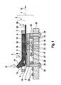
Figur 1- schematisch ein erfindungsgemäßes Analysesystem.
- FIG. 1
- schematically an inventive analysis system.
Das Analysesystem gemäß
Das Riegelelement 6 gemäß
Der zweite Hebelarm 11 enthält ein Schiebeelement 13, das beim Schwenken des Riegelelements 6 (aufgrund der Krafteinwirkung 12) aus der ersten in die zweite Position mittels der Schiebefläche 14 eine schiebende Kraft und/ oder ein Lösemoment auf das Testelement 4 in der Abgaberichtung 15 ausübt. Dadurch wird das Testelement 4 aus der Analyseposition gelöst und kann durch einen Benutzer aus der Testelement-Aufnahme in Abgaberichtung 15 herausgezogen und entsorgt werden.The second lever arm 11 includes a sliding
Das Analysesystem umfasst ferner eine Messanordnung mit einer Lichtquelle 16 (LED) und einem Detektor 17 (Photodiode). Die Lichtquelle 16 und der Detektor 17 sind so angeordnet, dass das durch die Lichtquelle 16 eingestrahlte Licht 18 durch einen lichtdurchlässigen Bereich 19 des Führungsteils 2 zu dem Testfeld 20 des in der Analyseposition angeordneten Testelements 4 gelangen kann. Der lichtdurchlässige Bereich 19 ist eine Blende, die durch ein Kunststofffenster gefüllt ist. Das an dem Testfeld 20 reflektierte Licht 21 gelangt wiederum durch den lichtdurchlässigen Bereich 19 zu dem Detektor 17, wobei ein Abschirmmittel 22 das eingestrahlte Licht 18 von dem reflektierten Licht 21 trennt. Die Lichtquelle 16 und der Detektor 17 sind auf einer Platine 23 angeordnet, an der das Führungsteil 2 mittels Fixierelementen 24 fixiert ist, wobei Abstandshalter 25 zwischen der Platine 23 und dem Führungsteil 2 angeordnet sind. Die Platine 23 trägt außerdem weitere Bauteile 26 des Analysesystems.The analysis system further comprises a measuring arrangement with a light source 16 (LED) and a detector 17 (photodiode). The
Auf der Platine 23 ist ferner ein Schalter 27 angeordnet, der über einen Schaltstößel 28 mit der Rastnase 8 so zusammenwirkt, dass er in der ersten Position des Riegelelements 6 (die in
Zur Durchführung einer Messung mit dem Analysesystem erfolgt eine Probenaufgabe 29 auf ein aus der Testelement-Aufnahme herausragendes Ende 30 des in der Analyseposition positionierten Testelements, von wo aus die Probe (zum Beispiel ein Blutstropfen) mittels einer (nicht dargestellten) Kapillare zum Testfeld 20 transportiert wird. Das dargestellte Analysesystem führt eine photometrische Messung zur Bestimmung der Konzentration eines Analyten in der Probe durch.To perform a measurement with the analysis system, a
- 11
- Testelement-AufnahmeTest element receptacle
- 22
- Führungsteilguide part
- 33
- Verriegelungsteillocking member
- 44
- Testelementtest element
- 55
- Rahmenframe
- 66
- Riegelelementlocking element
- 77
- Filmscharnierfilm hinge
- 88th
- Rastnaselocking lug
- 99
- Ausnehmungrecess
- 1010
- erster Hebelarmfirst lever arm
- 1111
- zweiter Hebelarmsecond lever arm
- 1212
- Krafteinwirkungforce
- 1313
- Schiebeelementsliding element
- 1414
- Schiebeflächesliding surface
- 1515
- Abgaberichtungdispensing direction
- 1616
- Lichtquellelight source
- 1717
- Detektordetector
- 1818
- eingestrahltes Lichtirradiated light
- 1919
- lichtdurchlässiger Bereichtranslucent area
- 2020
- Testfeldtest field
- 2121
- reflektiertes Lichtreflected light
- 2222
- Abschirmmittelscreening
- 2323
- Platinecircuit board
- 2424
- Fixierelementefixing
- 2525
- Abstandshalterspacer
- 2626
- weitere Bauteileother components
- 2727
- Schalterswitch
- 2828
- Schaltstößelswitching plunger
- 2929
- Probenaufgabesample application
- 3030
- Ende des TestelementsEnd of the test element
Claims (12)
- Analysis system for analysing a sample on an analytical test element (4), comprising a test element receptacle (1) for receiving and positioning a test element (4) in an analysis position, characterized in that the test element receptacle (1) contains a guide part (2) and a lock part (3), with the guide part (2) having means for guiding a test element (4) into and out of the analysis position, and the lock part (3) comprising a frame (5) and a bolt element (6), which frame and bolt element are connected to one another by means of a film hinge (7), it being possible to pivot the bolt element (6) out of a first position into a second position, which deforms the film hinge (7), with respect to the frame (5) about the film hinge (7), and the bolt element (6) comprising a latching lug (8) for engaging in a recess (9) in test element (4), which is positioned in the analysis position, in the first position of the bolt element (6), with the bolt element (6) being in the form of a lever, which can rotate about the film hinge (7), having a first and a second lever arm (10, 11), with the first lever arm (10) having the latching lug (8), and it being possible to pivot the bolt element (6) out of the first position into the second position by virtue of the action of force (12) on the second lever arm (11), with the second lever arm (11) containing a pushing element (13) which exerts a pushing force on a test element (4), which is positioned in the analysis position, in a discharge direction (15) when the bolt element (6) is pivoted out of the first position into the second position.
- Analysis system according to Claim 1, characterized in that the frame (5) and the bolt element (6) are integrally connected to one another by means of the film hinge (7).
- Analysis system according to either of Claims 1 and 2, characterized in that the lock part (3) and the guide part (2) are injection-moulded plastic parts.
- Analysis system according to one of Claims 1 to 3, characterized in that the test element receptacle (1) can be at least partially removed from the analysis system.
- Analysis system according to one of Claims 1 to 4, characterized in that the lock part (3) is releasably connected to the guide part (2).
- Analysis system according to one of Claims 1 to 5, characterized in that the bolt element (6) is prestressed in the first position.
- Analysis system according to one of Claims 1 to 6, comprising a measurement arrangement with a light source (16) and a detector (17) which are arranged such that light (18) from the light source (16) can pass through a light-transmissive region (19) of the guide part (2) to a test field (20) of a test element (4) which is arranged in the analysis position and, in a reflected manner (21), from the test field (20) through the light-transmissive region (19) to the detector (17).
- Analysis system according to Claim 7, characterized in that the light source (16) and the detector (17) are arranged on a printed circuit board (23) on which the guide part (2) is fixed, with at least one spacer (25) being arranged between the printed circuit board (23) and the guide part (2).
- Analysis system according to one of Claims 1 to 8, comprising a switch (28) which interacts with the latching lug (8) of the bolt element (6) such that the said switch is operated by the latching lug (8) in the first position of the bolt element (6).
- Method for analysis of a sample on an analytical test element in an analysis system, comprising the steps of• receiving a test element in a test element receptacle of the analysis system, with the test element being guided into an analysis position by means for guiding the test element in a guide part of the test element receptacle, and the test element being locked in the analysis position by a lock part of the test element receptacle, which has a frame and a bolt element which are connected to one another by means of a film hinge, by the bolt element pivoting about the film hinge out of a second position into a first position in which a latching lug of the bolt element engages in a recess in the test element which is positioned in the analysis position, and• analysing the sample in a test field of the test element using a measurement arrangement of the analysis system,with the test element being removed from the test element receptacle, with the bolt element being pivoted into the second position and in the process the latching lug automatically being moved out of the recess in the test element at the same time, and a pushing element, which is provided on the bolt element, exerting a force on the test element, which is positioned in the analysis position, in a discharge direction.
- Method according to Claim 10, characterized in that an optical scanning apparatus scans the test element along one surface when the test element is received in the test element receptacle.
- Use of an analysis system according to one of Claims 1 to 9 for measuring the concentration of glucose in a body fluid on a test strip.
Priority Applications (2)
| Application Number | Priority Date | Filing Date | Title |
|---|---|---|---|
| EP06117020.5A EP1879018B1 (en) | 2006-07-12 | 2006-07-12 | Analysis system and method for analysing a sample on an analytical test element |
| US11/776,379 US7951331B2 (en) | 2006-07-12 | 2007-07-11 | Analysis system and method for analyzing a sample on an analytical test element |
Applications Claiming Priority (1)
| Application Number | Priority Date | Filing Date | Title |
|---|---|---|---|
| EP06117020.5A EP1879018B1 (en) | 2006-07-12 | 2006-07-12 | Analysis system and method for analysing a sample on an analytical test element |
Publications (2)
| Publication Number | Publication Date |
|---|---|
| EP1879018A1 EP1879018A1 (en) | 2008-01-16 |
| EP1879018B1 true EP1879018B1 (en) | 2015-08-19 |
Family
ID=37575096
Family Applications (1)
| Application Number | Title | Priority Date | Filing Date |
|---|---|---|---|
| EP06117020.5A Not-in-force EP1879018B1 (en) | 2006-07-12 | 2006-07-12 | Analysis system and method for analysing a sample on an analytical test element |
Country Status (2)
| Country | Link |
|---|---|
| US (1) | US7951331B2 (en) |
| EP (1) | EP1879018B1 (en) |
Families Citing this family (54)
| Publication number | Priority date | Publication date | Assignee | Title |
|---|---|---|---|---|
| US6391005B1 (en) | 1998-03-30 | 2002-05-21 | Agilent Technologies, Inc. | Apparatus and method for penetration with shaft having a sensor for sensing penetration depth |
| US8641644B2 (en) | 2000-11-21 | 2014-02-04 | Sanofi-Aventis Deutschland Gmbh | Blood testing apparatus having a rotatable cartridge with multiple lancing elements and testing means |
| US9795747B2 (en) | 2010-06-02 | 2017-10-24 | Sanofi-Aventis Deutschland Gmbh | Methods and apparatus for lancet actuation |
| US7749174B2 (en) | 2001-06-12 | 2010-07-06 | Pelikan Technologies, Inc. | Method and apparatus for lancet launching device intergrated onto a blood-sampling cartridge |
| US9226699B2 (en) | 2002-04-19 | 2016-01-05 | Sanofi-Aventis Deutschland Gmbh | Body fluid sampling module with a continuous compression tissue interface surface |
| US7981056B2 (en) | 2002-04-19 | 2011-07-19 | Pelikan Technologies, Inc. | Methods and apparatus for lancet actuation |
| ATE485766T1 (en) | 2001-06-12 | 2010-11-15 | Pelikan Technologies Inc | ELECTRICAL ACTUATING ELEMENT FOR A LANCET |
| US7025774B2 (en) | 2001-06-12 | 2006-04-11 | Pelikan Technologies, Inc. | Tissue penetration device |
| US8337419B2 (en) | 2002-04-19 | 2012-12-25 | Sanofi-Aventis Deutschland Gmbh | Tissue penetration device |
| DE60234598D1 (en) | 2001-06-12 | 2010-01-14 | Pelikan Technologies Inc | SELF-OPTIMIZING LANZET DEVICE WITH ADAPTANT FOR TEMPORAL FLUCTUATIONS OF SKIN PROPERTIES |
| US9427532B2 (en) | 2001-06-12 | 2016-08-30 | Sanofi-Aventis Deutschland Gmbh | Tissue penetration device |
| US7976476B2 (en) | 2002-04-19 | 2011-07-12 | Pelikan Technologies, Inc. | Device and method for variable speed lancet |
| US7491178B2 (en) | 2002-04-19 | 2009-02-17 | Pelikan Technologies, Inc. | Method and apparatus for penetrating tissue |
| US7175642B2 (en) | 2002-04-19 | 2007-02-13 | Pelikan Technologies, Inc. | Methods and apparatus for lancet actuation |
| US9795334B2 (en) | 2002-04-19 | 2017-10-24 | Sanofi-Aventis Deutschland Gmbh | Method and apparatus for penetrating tissue |
| US7229458B2 (en) | 2002-04-19 | 2007-06-12 | Pelikan Technologies, Inc. | Method and apparatus for penetrating tissue |
| US9314194B2 (en) | 2002-04-19 | 2016-04-19 | Sanofi-Aventis Deutschland Gmbh | Tissue penetration device |
| US7909778B2 (en) | 2002-04-19 | 2011-03-22 | Pelikan Technologies, Inc. | Method and apparatus for penetrating tissue |
| US8267870B2 (en) | 2002-04-19 | 2012-09-18 | Sanofi-Aventis Deutschland Gmbh | Method and apparatus for body fluid sampling with hybrid actuation |
| US7674232B2 (en) | 2002-04-19 | 2010-03-09 | Pelikan Technologies, Inc. | Method and apparatus for penetrating tissue |
| US7226461B2 (en) | 2002-04-19 | 2007-06-05 | Pelikan Technologies, Inc. | Method and apparatus for a multi-use body fluid sampling device with sterility barrier release |
| US9248267B2 (en) | 2002-04-19 | 2016-02-02 | Sanofi-Aventis Deustchland Gmbh | Tissue penetration device |
| US7892183B2 (en) | 2002-04-19 | 2011-02-22 | Pelikan Technologies, Inc. | Method and apparatus for body fluid sampling and analyte sensing |
| US8702624B2 (en) | 2006-09-29 | 2014-04-22 | Sanofi-Aventis Deutschland Gmbh | Analyte measurement device with a single shot actuator |
| US7547287B2 (en) | 2002-04-19 | 2009-06-16 | Pelikan Technologies, Inc. | Method and apparatus for penetrating tissue |
| US8360992B2 (en) | 2002-04-19 | 2013-01-29 | Sanofi-Aventis Deutschland Gmbh | Method and apparatus for penetrating tissue |
| US8221334B2 (en) | 2002-04-19 | 2012-07-17 | Sanofi-Aventis Deutschland Gmbh | Method and apparatus for penetrating tissue |
| US8784335B2 (en) | 2002-04-19 | 2014-07-22 | Sanofi-Aventis Deutschland Gmbh | Body fluid sampling device with a capacitive sensor |
| US8579831B2 (en) | 2002-04-19 | 2013-11-12 | Sanofi-Aventis Deutschland Gmbh | Method and apparatus for penetrating tissue |
| US7331931B2 (en) | 2002-04-19 | 2008-02-19 | Pelikan Technologies, Inc. | Method and apparatus for penetrating tissue |
| US7892185B2 (en) | 2002-04-19 | 2011-02-22 | Pelikan Technologies, Inc. | Method and apparatus for body fluid sampling and analyte sensing |
| US7901362B2 (en) | 2002-04-19 | 2011-03-08 | Pelikan Technologies, Inc. | Method and apparatus for penetrating tissue |
| US7232451B2 (en) | 2002-04-19 | 2007-06-19 | Pelikan Technologies, Inc. | Method and apparatus for penetrating tissue |
| US7297122B2 (en) | 2002-04-19 | 2007-11-20 | Pelikan Technologies, Inc. | Method and apparatus for penetrating tissue |
| US8574895B2 (en) | 2002-12-30 | 2013-11-05 | Sanofi-Aventis Deutschland Gmbh | Method and apparatus using optical techniques to measure analyte levels |
| EP1628567B1 (en) | 2003-05-30 | 2010-08-04 | Pelikan Technologies Inc. | Method and apparatus for fluid injection |
| DK1633235T3 (en) | 2003-06-06 | 2014-08-18 | Sanofi Aventis Deutschland | Apparatus for sampling body fluid and detecting analyte |
| WO2006001797A1 (en) | 2004-06-14 | 2006-01-05 | Pelikan Technologies, Inc. | Low pain penetrating |
| US8282576B2 (en) | 2003-09-29 | 2012-10-09 | Sanofi-Aventis Deutschland Gmbh | Method and apparatus for an improved sample capture device |
| EP1680014A4 (en) | 2003-10-14 | 2009-01-21 | Pelikan Technologies Inc | Method and apparatus for a variable user interface |
| EP1706026B1 (en) | 2003-12-31 | 2017-03-01 | Sanofi-Aventis Deutschland GmbH | Method and apparatus for improving fluidic flow and sample capture |
| US7822454B1 (en) | 2005-01-03 | 2010-10-26 | Pelikan Technologies, Inc. | Fluid sampling device with improved analyte detecting member configuration |
| US8828203B2 (en) | 2004-05-20 | 2014-09-09 | Sanofi-Aventis Deutschland Gmbh | Printable hydrogels for biosensors |
| US9775553B2 (en) | 2004-06-03 | 2017-10-03 | Sanofi-Aventis Deutschland Gmbh | Method and apparatus for a fluid sampling device |
| EP1765194A4 (en) | 2004-06-03 | 2010-09-29 | Pelikan Technologies Inc | Method and apparatus for a fluid sampling device |
| US8652831B2 (en) | 2004-12-30 | 2014-02-18 | Sanofi-Aventis Deutschland Gmbh | Method and apparatus for analyte measurement test time |
| EP1736774B1 (en) * | 2005-06-22 | 2008-02-06 | F.Hoffmann-La Roche Ag | Analytic system for the analysis of a sample on an analytic test element |
| SI1972275T1 (en) * | 2007-03-20 | 2016-02-29 | F. Hoffmann-La Roche Ag | System for in vivo measurement of an analyte concentration |
| WO2009126900A1 (en) | 2008-04-11 | 2009-10-15 | Pelikan Technologies, Inc. | Method and apparatus for analyte detecting device |
| US9375169B2 (en) | 2009-01-30 | 2016-06-28 | Sanofi-Aventis Deutschland Gmbh | Cam drive for managing disposable penetrating member actions with a single motor and motor and control system |
| GB0918462D0 (en) * | 2009-10-21 | 2009-12-09 | Spd Swiss Prec Diagnostics Gmb | Connection assembly and method |
| US8965476B2 (en) | 2010-04-16 | 2015-02-24 | Sanofi-Aventis Deutschland Gmbh | Tissue penetration device |
| JP5808653B2 (en) * | 2011-11-18 | 2015-11-10 | シスメックス株式会社 | Blood cell counter and blood cell counter method |
| CN115494100B (en) * | 2022-11-17 | 2023-03-14 | 济南弗莱德科技有限公司 | Online oil analyzer |
Family Cites Families (19)
| Publication number | Priority date | Publication date | Assignee | Title |
|---|---|---|---|---|
| EP0167661A1 (en) * | 1984-06-28 | 1986-01-15 | ZELLER PLASTIK Koehn, Gräbner & Co. | Plastic snap-hinge |
| DE8716270U1 (en) * | 1987-12-09 | 1988-02-18 | Lre Relais + Elektronik Gmbh, 8000 Muenchen, De | |
| DE3844103A1 (en) * | 1988-12-28 | 1990-07-05 | Boehringer Mannheim Gmbh | TEST CARRIER ANALYSIS SYSTEM |
| DE3921391A1 (en) * | 1989-06-29 | 1991-01-10 | Lre Relais & Elektronik Gmbh | DEVICE FOR REMISSION-PHOTOMETRIC ANALYSIS OF LIQUID SAMPLES |
| US5313721A (en) * | 1992-08-28 | 1994-05-24 | Gerhard Filden | Pocket clip for card cases, identification badges and the like |
| DE4310583A1 (en) * | 1993-03-31 | 1994-10-06 | Boehringer Mannheim Gmbh | Test strip analysis system |
| DK0622119T3 (en) * | 1993-04-23 | 2000-04-10 | Roche Diagnostics Gmbh | Test element storage system |
| DE4328816A1 (en) * | 1993-08-27 | 1995-03-02 | Boehringer Mannheim Gmbh | System for storing test elements |
| FR2710414A1 (en) | 1993-09-21 | 1995-03-31 | Asulab Sa | Measuring device for removable multi-zone sensors comprising an ejection system for these sensors. |
| US5762770A (en) | 1994-02-21 | 1998-06-09 | Boehringer Mannheim Corporation | Electrochemical biosensor test strip |
| DE19629657A1 (en) | 1996-07-23 | 1998-01-29 | Boehringer Mannheim Gmbh | Volume-independent diagnostic test carrier and method for determining analyte with its aid |
| DE19629656A1 (en) | 1996-07-23 | 1998-01-29 | Boehringer Mannheim Gmbh | Diagnostic test carrier with multilayer test field and method for the determination of analyte with its aid |
| DE19714674A1 (en) * | 1997-04-09 | 1998-10-15 | Lre Technology Partner Gmbh | Test strip pack and measuring device for using one |
| DE19753847A1 (en) | 1997-12-04 | 1999-06-10 | Roche Diagnostics Gmbh | Analytical test element with capillary channel |
| DE19811622A1 (en) * | 1998-03-17 | 1999-09-23 | Lre Technology Partner Gmbh | Laboratory instrument incorporating split test card housing |
| DE19822770B4 (en) * | 1998-05-20 | 2012-04-12 | Lre Technology Partner Gmbh | Test strip system |
| DE19844500A1 (en) * | 1998-09-29 | 2000-03-30 | Roche Diagnostics Gmbh | Process for the photometric evaluation of test elements |
| DE10084176D2 (en) | 1999-12-24 | 2003-01-16 | Roche Diagnostics Gmbh | Test element analysis system |
| DE10338446A1 (en) * | 2003-08-21 | 2005-03-31 | Roche Diagnostics Gmbh | Positioning device for a test element |
-
2006
- 2006-07-12 EP EP06117020.5A patent/EP1879018B1/en not_active Not-in-force
-
2007
- 2007-07-11 US US11/776,379 patent/US7951331B2/en not_active Expired - Fee Related
Also Published As
| Publication number | Publication date |
|---|---|
| EP1879018A1 (en) | 2008-01-16 |
| US7951331B2 (en) | 2011-05-31 |
| US20080053201A1 (en) | 2008-03-06 |
Similar Documents
| Publication | Publication Date | Title |
|---|---|---|
| EP1879018B1 (en) | Analysis system and method for analysing a sample on an analytical test element | |
| EP1736774B1 (en) | Analytic system for the analysis of a sample on an analytic test element | |
| DE10325699B3 (en) | System for analyzing a sample to be tested and using such a system | |
| EP2130493B1 (en) | Analysis system for detecting an analyte in a bodily fluid, cartridge for an analytic device and method for manufacturing a cartridge for an analysis system. | |
| EP1238274B1 (en) | Test element analysis system with infrared detector | |
| EP1117989B1 (en) | Method for the photometric analysis of test elements | |
| EP1240503B1 (en) | Test strip analysis system, medical test strip, and method of analysing a sample by the help of a test strip analysis system | |
| EP1705480B1 (en) | Test element for analysing body fluids | |
| DE60315373T2 (en) | Apparatus and method for determining the concentration of analytes | |
| DE69825107T2 (en) | A negative pressure generating device and a sample analyzing device for use with such a negative pressure generating device | |
| EP1213579B1 (en) | System for the liquid sample analysis comprising a position control unit | |
| EP1921441B1 (en) | Method for analysing a sample on a test element and analysis system | |
| EP1461603A2 (en) | Analysis system for determining an analyte concentration, taking into consideration sample- and analyte-independent light-intensity changes | |
| EP1982653A1 (en) | Pricking device and analysis device | |
| EP2221608A1 (en) | Test device and method for examining a bodily fluid | |
| DE102011086740A1 (en) | Detection device for recording vital signs | |
| EP2244086A2 (en) | Analysis of optical data using histograms | |
| WO2003095092A1 (en) | Sampling device for liquid samples | |
| EP1411346B1 (en) | Method for detection and compensation of the underdosage of test strips | |
| EP1995594B1 (en) | Handheld analysis device for investigating a sample | |
| EP2427101B1 (en) | Test unit for use in an test device and test system | |
| EP1508807B1 (en) | Positioning device for a test element |
Legal Events
| Date | Code | Title | Description |
|---|---|---|---|
| PUAI | Public reference made under article 153(3) epc to a published international application that has entered the european phase |
Free format text: ORIGINAL CODE: 0009012 |
|
| AK | Designated contracting states |
Kind code of ref document: A1 Designated state(s): AT BE BG CH CY CZ DE DK EE ES FI FR GB GR HU IE IS IT LI LT LU LV MC NL PL PT RO SE SI SK TR |
|
| AX | Request for extension of the european patent |
Extension state: AL BA HR MK YU |
|
| 17P | Request for examination filed |
Effective date: 20080620 |
|
| RAP1 | Party data changed (applicant data changed or rights of an application transferred) |
Owner name: F. HOFFMANN-LA ROCHE AG Owner name: ROCHE DIAGNOSTICS GMBH |
|
| AKX | Designation fees paid |
Designated state(s): AT BE BG CH CY CZ DE DK EE ES FI FR GB GR HU IE IS IT LI LT LU LV MC NL PL PT RO SE SI SK TR |
|
| 17Q | First examination report despatched |
Effective date: 20100416 |
|
| REG | Reference to a national code |
Ref country code: DE Ref legal event code: R079 Ref document number: 502006014490 Country of ref document: DE Free format text: PREVIOUS MAIN CLASS: G01N0021860000 Ipc: G01N0021010000 |
|
| GRAP | Despatch of communication of intention to grant a patent |
Free format text: ORIGINAL CODE: EPIDOSNIGR1 |
|
| RIC1 | Information provided on ipc code assigned before grant |
Ipc: G01N 21/47 20060101ALI20150310BHEP Ipc: G01N 21/84 20060101ALI20150310BHEP Ipc: G01N 21/01 20060101AFI20150310BHEP |
|
| INTG | Intention to grant announced |
Effective date: 20150324 |
|
| GRAS | Grant fee paid |
Free format text: ORIGINAL CODE: EPIDOSNIGR3 |
|
| GRAA | (expected) grant |
Free format text: ORIGINAL CODE: 0009210 |
|
| AK | Designated contracting states |
Kind code of ref document: B1 Designated state(s): AT BE BG CH CY CZ DE DK EE ES FI FR GB GR HU IE IS IT LI LT LU LV MC NL PL PT RO SE SI SK TR |
|
| RAP1 | Party data changed (applicant data changed or rights of an application transferred) |
Owner name: F. HOFFMANN-LA ROCHE AG Owner name: ROCHE DIAGNOSTICS GMBH |
|
| REG | Reference to a national code |
Ref country code: GB Ref legal event code: FG4D Free format text: NOT ENGLISH |
|
| REG | Reference to a national code |
Ref country code: CH Ref legal event code: EP |
|
| REG | Reference to a national code |
Ref country code: IE Ref legal event code: FG4D Free format text: LANGUAGE OF EP DOCUMENT: GERMAN |
|
| REG | Reference to a national code |
Ref country code: AT Ref legal event code: REF Ref document number: 744156 Country of ref document: AT Kind code of ref document: T Effective date: 20150915 |
|
| REG | Reference to a national code |
Ref country code: DE Ref legal event code: R096 Ref document number: 502006014490 Country of ref document: DE |
|
| REG | Reference to a national code |
Ref country code: LT Ref legal event code: MG4D |
|
| REG | Reference to a national code |
Ref country code: NL Ref legal event code: MP Effective date: 20150819 |
|
| PG25 | Lapsed in a contracting state [announced via postgrant information from national office to epo] |
Ref country code: GR Free format text: LAPSE BECAUSE OF FAILURE TO SUBMIT A TRANSLATION OF THE DESCRIPTION OR TO PAY THE FEE WITHIN THE PRESCRIBED TIME-LIMIT Effective date: 20151120 Ref country code: LT Free format text: LAPSE BECAUSE OF FAILURE TO SUBMIT A TRANSLATION OF THE DESCRIPTION OR TO PAY THE FEE WITHIN THE PRESCRIBED TIME-LIMIT Effective date: 20150819 Ref country code: FI Free format text: LAPSE BECAUSE OF FAILURE TO SUBMIT A TRANSLATION OF THE DESCRIPTION OR TO PAY THE FEE WITHIN THE PRESCRIBED TIME-LIMIT Effective date: 20150819 Ref country code: LV Free format text: LAPSE BECAUSE OF FAILURE TO SUBMIT A TRANSLATION OF THE DESCRIPTION OR TO PAY THE FEE WITHIN THE PRESCRIBED TIME-LIMIT Effective date: 20150819 |
|
| PG25 | Lapsed in a contracting state [announced via postgrant information from national office to epo] |
Ref country code: PT Free format text: LAPSE BECAUSE OF FAILURE TO SUBMIT A TRANSLATION OF THE DESCRIPTION OR TO PAY THE FEE WITHIN THE PRESCRIBED TIME-LIMIT Effective date: 20151221 Ref country code: IS Free format text: LAPSE BECAUSE OF FAILURE TO SUBMIT A TRANSLATION OF THE DESCRIPTION OR TO PAY THE FEE WITHIN THE PRESCRIBED TIME-LIMIT Effective date: 20151219 Ref country code: SE Free format text: LAPSE BECAUSE OF FAILURE TO SUBMIT A TRANSLATION OF THE DESCRIPTION OR TO PAY THE FEE WITHIN THE PRESCRIBED TIME-LIMIT Effective date: 20150819 Ref country code: PL Free format text: LAPSE BECAUSE OF FAILURE TO SUBMIT A TRANSLATION OF THE DESCRIPTION OR TO PAY THE FEE WITHIN THE PRESCRIBED TIME-LIMIT Effective date: 20150819 Ref country code: ES Free format text: LAPSE BECAUSE OF FAILURE TO SUBMIT A TRANSLATION OF THE DESCRIPTION OR TO PAY THE FEE WITHIN THE PRESCRIBED TIME-LIMIT Effective date: 20150819 |
|
| PG25 | Lapsed in a contracting state [announced via postgrant information from national office to epo] |
Ref country code: NL Free format text: LAPSE BECAUSE OF FAILURE TO SUBMIT A TRANSLATION OF THE DESCRIPTION OR TO PAY THE FEE WITHIN THE PRESCRIBED TIME-LIMIT Effective date: 20150819 |
|
| REG | Reference to a national code |
Ref country code: DE Ref legal event code: R081 Ref document number: 502006014490 Country of ref document: DE Owner name: ROCHE DIABETES CARE GMBH, DE Free format text: FORMER OWNER: ROCHE DIAGNOSTICS GMBH, 68305 MANNHEIM, DE |
|
| PG25 | Lapsed in a contracting state [announced via postgrant information from national office to epo] |
Ref country code: IT Free format text: LAPSE BECAUSE OF FAILURE TO SUBMIT A TRANSLATION OF THE DESCRIPTION OR TO PAY THE FEE WITHIN THE PRESCRIBED TIME-LIMIT Effective date: 20150819 Ref country code: DK Free format text: LAPSE BECAUSE OF FAILURE TO SUBMIT A TRANSLATION OF THE DESCRIPTION OR TO PAY THE FEE WITHIN THE PRESCRIBED TIME-LIMIT Effective date: 20150819 Ref country code: CZ Free format text: LAPSE BECAUSE OF FAILURE TO SUBMIT A TRANSLATION OF THE DESCRIPTION OR TO PAY THE FEE WITHIN THE PRESCRIBED TIME-LIMIT Effective date: 20150819 Ref country code: SK Free format text: LAPSE BECAUSE OF FAILURE TO SUBMIT A TRANSLATION OF THE DESCRIPTION OR TO PAY THE FEE WITHIN THE PRESCRIBED TIME-LIMIT Effective date: 20150819 Ref country code: EE Free format text: LAPSE BECAUSE OF FAILURE TO SUBMIT A TRANSLATION OF THE DESCRIPTION OR TO PAY THE FEE WITHIN THE PRESCRIBED TIME-LIMIT Effective date: 20150819 |
|
| REG | Reference to a national code |
Ref country code: DE Ref legal event code: R097 Ref document number: 502006014490 Country of ref document: DE |
|
| PG25 | Lapsed in a contracting state [announced via postgrant information from national office to epo] |
Ref country code: RO Free format text: LAPSE BECAUSE OF FAILURE TO SUBMIT A TRANSLATION OF THE DESCRIPTION OR TO PAY THE FEE WITHIN THE PRESCRIBED TIME-LIMIT Effective date: 20150819 |
|
| PLBE | No opposition filed within time limit |
Free format text: ORIGINAL CODE: 0009261 |
|
| STAA | Information on the status of an ep patent application or granted ep patent |
Free format text: STATUS: NO OPPOSITION FILED WITHIN TIME LIMIT |
|
| 26N | No opposition filed |
Effective date: 20160520 |
|
| PG25 | Lapsed in a contracting state [announced via postgrant information from national office to epo] |
Ref country code: SI Free format text: LAPSE BECAUSE OF FAILURE TO SUBMIT A TRANSLATION OF THE DESCRIPTION OR TO PAY THE FEE WITHIN THE PRESCRIBED TIME-LIMIT Effective date: 20150819 |
|
| PGFP | Annual fee paid to national office [announced via postgrant information from national office to epo] |
Ref country code: DE Payment date: 20160801 Year of fee payment: 11 |
|
| PG25 | Lapsed in a contracting state [announced via postgrant information from national office to epo] |
Ref country code: BE Free format text: LAPSE BECAUSE OF NON-PAYMENT OF DUE FEES Effective date: 20160731 |
|
| REG | Reference to a national code |
Ref country code: CH Ref legal event code: PL |
|
| GBPC | Gb: european patent ceased through non-payment of renewal fee |
Effective date: 20160712 |
|
| PG25 | Lapsed in a contracting state [announced via postgrant information from national office to epo] |
Ref country code: MC Free format text: LAPSE BECAUSE OF FAILURE TO SUBMIT A TRANSLATION OF THE DESCRIPTION OR TO PAY THE FEE WITHIN THE PRESCRIBED TIME-LIMIT Effective date: 20150819 |
|
| PG25 | Lapsed in a contracting state [announced via postgrant information from national office to epo] |
Ref country code: LI Free format text: LAPSE BECAUSE OF NON-PAYMENT OF DUE FEES Effective date: 20160731 Ref country code: FR Free format text: LAPSE BECAUSE OF NON-PAYMENT OF DUE FEES Effective date: 20160801 Ref country code: CH Free format text: LAPSE BECAUSE OF NON-PAYMENT OF DUE FEES Effective date: 20160731 |
|
| REG | Reference to a national code |
Ref country code: FR Ref legal event code: ST Effective date: 20170331 |
|
| REG | Reference to a national code |
Ref country code: IE Ref legal event code: MM4A |
|
| PG25 | Lapsed in a contracting state [announced via postgrant information from national office to epo] |
Ref country code: GB Free format text: LAPSE BECAUSE OF NON-PAYMENT OF DUE FEES Effective date: 20160712 |
|
| PG25 | Lapsed in a contracting state [announced via postgrant information from national office to epo] |
Ref country code: IE Free format text: LAPSE BECAUSE OF NON-PAYMENT OF DUE FEES Effective date: 20160712 |
|
| PG25 | Lapsed in a contracting state [announced via postgrant information from national office to epo] |
Ref country code: LU Free format text: LAPSE BECAUSE OF NON-PAYMENT OF DUE FEES Effective date: 20160712 |
|
| REG | Reference to a national code |
Ref country code: AT Ref legal event code: MM01 Ref document number: 744156 Country of ref document: AT Kind code of ref document: T Effective date: 20160712 |
|
| PG25 | Lapsed in a contracting state [announced via postgrant information from national office to epo] |
Ref country code: AT Free format text: LAPSE BECAUSE OF NON-PAYMENT OF DUE FEES Effective date: 20160712 |
|
| REG | Reference to a national code |
Ref country code: DE Ref legal event code: R119 Ref document number: 502006014490 Country of ref document: DE |
|
| PG25 | Lapsed in a contracting state [announced via postgrant information from national office to epo] |
Ref country code: DE Free format text: LAPSE BECAUSE OF NON-PAYMENT OF DUE FEES Effective date: 20180201 |
|
| PG25 | Lapsed in a contracting state [announced via postgrant information from national office to epo] |
Ref country code: HU Free format text: LAPSE BECAUSE OF FAILURE TO SUBMIT A TRANSLATION OF THE DESCRIPTION OR TO PAY THE FEE WITHIN THE PRESCRIBED TIME-LIMIT; INVALID AB INITIO Effective date: 20060712 Ref country code: CY Free format text: LAPSE BECAUSE OF FAILURE TO SUBMIT A TRANSLATION OF THE DESCRIPTION OR TO PAY THE FEE WITHIN THE PRESCRIBED TIME-LIMIT Effective date: 20150819 |
|
| PG25 | Lapsed in a contracting state [announced via postgrant information from national office to epo] |
Ref country code: TR Free format text: LAPSE BECAUSE OF FAILURE TO SUBMIT A TRANSLATION OF THE DESCRIPTION OR TO PAY THE FEE WITHIN THE PRESCRIBED TIME-LIMIT Effective date: 20150819 |
|
| PG25 | Lapsed in a contracting state [announced via postgrant information from national office to epo] |
Ref country code: BG Free format text: LAPSE BECAUSE OF FAILURE TO SUBMIT A TRANSLATION OF THE DESCRIPTION OR TO PAY THE FEE WITHIN THE PRESCRIBED TIME-LIMIT Effective date: 20150819 |