EP2016899B1 - Device for extracting body fluids - Google Patents
Device for extracting body fluids Download PDFInfo
- Publication number
- EP2016899B1 EP2016899B1 EP07112625A EP07112625A EP2016899B1 EP 2016899 B1 EP2016899 B1 EP 2016899B1 EP 07112625 A EP07112625 A EP 07112625A EP 07112625 A EP07112625 A EP 07112625A EP 2016899 B1 EP2016899 B1 EP 2016899B1
- Authority
- EP
- European Patent Office
- Prior art keywords
- lancing element
- skin
- lancing
- actuator
- body fluid
- Prior art date
- Legal status (The legal status is an assumption and is not a legal conclusion. Google has not performed a legal analysis and makes no representation as to the accuracy of the status listed.)
- Not-in-force
Links
Images

Classifications
-
- A—HUMAN NECESSITIES
- A61—MEDICAL OR VETERINARY SCIENCE; HYGIENE
- A61B—DIAGNOSIS; SURGERY; IDENTIFICATION
- A61B5/00—Measuring for diagnostic purposes; Identification of persons
- A61B5/15—Devices for taking samples of blood
- A61B5/151—Devices specially adapted for taking samples of capillary blood, e.g. by lancets, needles or blades
- A61B5/15186—Devices loaded with a single lancet, i.e. a single lancet with or without a casing is loaded into a reusable drive device and then discarded after use; drive devices reloadable for multiple use
- A61B5/15188—Constructional features of reusable driving devices
- A61B5/15192—Constructional features of reusable driving devices comprising driving means, e.g. a spring, for retracting the lancet unit into the driving device housing
- A61B5/15194—Constructional features of reusable driving devices comprising driving means, e.g. a spring, for retracting the lancet unit into the driving device housing fully automatically retracted, i.e. the retraction does not require a deliberate action by the user, e.g. by terminating the contact with the patient's skin
-
- A—HUMAN NECESSITIES
- A61—MEDICAL OR VETERINARY SCIENCE; HYGIENE
- A61B—DIAGNOSIS; SURGERY; IDENTIFICATION
- A61B5/00—Measuring for diagnostic purposes; Identification of persons
- A61B5/15—Devices for taking samples of blood
- A61B5/150007—Details
- A61B5/150015—Source of blood
- A61B5/150022—Source of blood for capillary blood or interstitial fluid
-
- A—HUMAN NECESSITIES
- A61—MEDICAL OR VETERINARY SCIENCE; HYGIENE
- A61B—DIAGNOSIS; SURGERY; IDENTIFICATION
- A61B5/00—Measuring for diagnostic purposes; Identification of persons
- A61B5/15—Devices for taking samples of blood
- A61B5/150007—Details
- A61B5/150175—Adjustment of penetration depth
- A61B5/15019—Depth adjustment mechanism using movable stops located inside the piercing device housing and limiting the travel of the drive mechanism
-
- A—HUMAN NECESSITIES
- A61—MEDICAL OR VETERINARY SCIENCE; HYGIENE
- A61B—DIAGNOSIS; SURGERY; IDENTIFICATION
- A61B5/00—Measuring for diagnostic purposes; Identification of persons
- A61B5/15—Devices for taking samples of blood
- A61B5/150007—Details
- A61B5/150358—Strips for collecting blood, e.g. absorbent
-
- A—HUMAN NECESSITIES
- A61—MEDICAL OR VETERINARY SCIENCE; HYGIENE
- A61B—DIAGNOSIS; SURGERY; IDENTIFICATION
- A61B5/00—Measuring for diagnostic purposes; Identification of persons
- A61B5/15—Devices for taking samples of blood
- A61B5/150007—Details
- A61B5/150374—Details of piercing elements or protective means for preventing accidental injuries by such piercing elements
- A61B5/150381—Design of piercing elements
- A61B5/150412—Pointed piercing elements, e.g. needles, lancets for piercing the skin
- A61B5/150419—Pointed piercing elements, e.g. needles, lancets for piercing the skin comprising means for capillary action
-
- A—HUMAN NECESSITIES
- A61—MEDICAL OR VETERINARY SCIENCE; HYGIENE
- A61B—DIAGNOSIS; SURGERY; IDENTIFICATION
- A61B5/00—Measuring for diagnostic purposes; Identification of persons
- A61B5/15—Devices for taking samples of blood
- A61B5/150007—Details
- A61B5/150374—Details of piercing elements or protective means for preventing accidental injuries by such piercing elements
- A61B5/150381—Design of piercing elements
- A61B5/150412—Pointed piercing elements, e.g. needles, lancets for piercing the skin
- A61B5/150435—Specific design of proximal end
-
- A—HUMAN NECESSITIES
- A61—MEDICAL OR VETERINARY SCIENCE; HYGIENE
- A61B—DIAGNOSIS; SURGERY; IDENTIFICATION
- A61B5/00—Measuring for diagnostic purposes; Identification of persons
- A61B5/15—Devices for taking samples of blood
- A61B5/150007—Details
- A61B5/150374—Details of piercing elements or protective means for preventing accidental injuries by such piercing elements
- A61B5/150381—Design of piercing elements
- A61B5/150503—Single-ended needles
-
- A—HUMAN NECESSITIES
- A61—MEDICAL OR VETERINARY SCIENCE; HYGIENE
- A61B—DIAGNOSIS; SURGERY; IDENTIFICATION
- A61B5/00—Measuring for diagnostic purposes; Identification of persons
- A61B5/15—Devices for taking samples of blood
- A61B5/151—Devices specially adapted for taking samples of capillary blood, e.g. by lancets, needles or blades
- A61B5/15101—Details
- A61B5/15115—Driving means for propelling the piercing element to pierce the skin, e.g. comprising mechanisms based on shape memory alloys, magnetism, solenoids, piezoelectric effect, biased elements, resilient elements, vacuum or compressed fluids
- A61B5/15117—Driving means for propelling the piercing element to pierce the skin, e.g. comprising mechanisms based on shape memory alloys, magnetism, solenoids, piezoelectric effect, biased elements, resilient elements, vacuum or compressed fluids comprising biased elements, resilient elements or a spring, e.g. a helical spring, leaf spring, or elastic strap
-
- A—HUMAN NECESSITIES
- A61—MEDICAL OR VETERINARY SCIENCE; HYGIENE
- A61B—DIAGNOSIS; SURGERY; IDENTIFICATION
- A61B5/00—Measuring for diagnostic purposes; Identification of persons
- A61B5/15—Devices for taking samples of blood
- A61B5/151—Devices specially adapted for taking samples of capillary blood, e.g. by lancets, needles or blades
- A61B5/15101—Details
- A61B5/15126—Means for controlling the lancing movement, e.g. 2D- or 3D-shaped elements, tooth-shaped elements or sliding guides
- A61B5/15128—Means for controlling the lancing movement, e.g. 2D- or 3D-shaped elements, tooth-shaped elements or sliding guides comprising 2D- or 3D-shaped elements, e.g. cams, curved guide rails or threads
-
- A—HUMAN NECESSITIES
- A61—MEDICAL OR VETERINARY SCIENCE; HYGIENE
- A61B—DIAGNOSIS; SURGERY; IDENTIFICATION
- A61B5/00—Measuring for diagnostic purposes; Identification of persons
- A61B5/15—Devices for taking samples of blood
- A61B5/151—Devices specially adapted for taking samples of capillary blood, e.g. by lancets, needles or blades
- A61B5/15186—Devices loaded with a single lancet, i.e. a single lancet with or without a casing is loaded into a reusable drive device and then discarded after use; drive devices reloadable for multiple use
- A61B5/15188—Constructional features of reusable driving devices
- A61B5/1519—Constructional features of reusable driving devices comprising driving means, e.g. a spring, for propelling the piercing unit
Definitions
- the invention relates to a device for obtaining body fluid, in particular blood, with a piercing element having a tip for piercing the skin of a body part and an actuator coupled to the piercing element for forward and backward movement of the piercing element, the piercing element being up to an optionally adjustable Piercing position is pierceable into the skin.
- the invention further relates to a corresponding method.
- the Laid-open publication DE 196 04 156 A1 discloses an oscillating blade cutter for creating a tissue incision.
- the blood fluid emerging from the wound thus produced can then be applied to a blood test strip by a user.
- the invention has for its object to optimize a generic device and thus a feasible method in the sense of a pain reduction, wherein a goal of the invention also consists in a reduction of the manufacturing effort.
- the invention is based on the finding that even surprisingly slow lancing speeds can be used without this causing an increased sense of pain in the user. Accordingly, the invention proposes that the actuator for propelling the piercing element forward to a penetration rate when penetrating into the skin of not more than 0.7 m / s and preferably between 0.4 to 0.5 m / s is formed. This makes it possible that stopping the tip of the puncturing element under the skin due to the reduced speed with less vibration and thus reduced pain is connected. Due to the reduced puncturing or penetration speed, the required accelerations or decelerations are reduced even at low puncturing depths, which in turn results in lower vibrational excitations of all components involved in the mechanism. As a result, the likelihood that the lancet moves exactly on its piercing axis, without transverse movements being superimposed, is increased, especially for hand-held devices constructed as mass-produced articles of plastic parts.
- the actuator is set up so that the piercing element is accelerated until it penetrates into the skin. In this way, the device-side effort can be further reduced.
- the average speed of the lancing element in the forward movement is less than 100 times the average speed of the lancing element in the return movement. This is particularly important in systems that use both a single-step function and the sample fluid for the Record analysis.
- the speed ratio specified for the entire sequence of movements also applies to the sole consideration of the skin intervention.
- the actuator is designed to withdraw the lancing element from the skin during the return movement at an average speed of between 1 and 10 mm / s, in particular between 3 and 9 mm / s.
- the average rate of withdrawal from the skin determines the collection time for blood collection at a given puncture depth. It should be sufficient for a successful collection process, if the actuator retracts the lancing element during a withdrawal time between 200 ms and 800 ms, in particular between 250 ms and 750 ms from the deepest puncture position to the skin surface.
- the deepest puncture position lies in the range between 1 and 2 mm, in particular at about 1.2 mm.
- the lancing element has a collecting structure, in particular a capillary for receiving the body fluid, so that an analysis in one go is possible.
- a further improvement with regard to a defined puncture can be achieved by a positioning device designed for positioning the body part in a lancing region of the piercing element.
- test elements For the detection of an ingredient of the body fluid obtained with the lancing element, a suitably designed test element can be provided. Such test elements may be based on optical or electrochemical detection of a target substance.
- the necessary sequence control of the puncturing movement can preferably be realized in that the actuator has a preferably spring-driven linkage drive.
- the actuator or the puncturing element cooperates with a stop or damper for limiting the forward movement of the lancing element.
- the piercing element should be guided rectilinearly in a linear guide at least over part of its length in the direction of movement.
- the puncturing element is formed from a round wire with a diameter of less than 0.5 mm or from a flat material with a thickness of less than 0.2 mm.
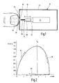
- the device 10 shown in the drawing comprises an actuator 12 for driving a piercing element 14 in a forward and backward movement 16, wherein the piercing element 14 is pierced into the skin 18 of a finger 20 up to an optionally adjustable piercing position or piercing depth.
- an actuator 12 for driving a piercing element 14 in a forward and backward movement 16, wherein the piercing element 14 is pierced into the skin 18 of a finger 20 up to an optionally adjustable piercing position or piercing depth.
- the actuator 12 is designed so that the penetration speed of the lancing element 14 is limited to a pain-poor puncture to about 0.4 to 0.5 m / s.
- Fig. 1 illustrated may be provided on the device housing 22 has an opening 24 for defined finger positioning.
- the piercing element 14 can be moved with its distal tip 26 into the region of the opening 24 in order to gain blood and / or tissue fluid by puncturing the skin 18.
- the finger positioning can promote the blood flow in the puncture wound as it were by milking the finger.
- the body fluid is absorbed by an optionally hydrophilically coated capillary 28 of the piercing element 14, which is fluidically connected or connectable to an analytical test field 30.
- the lancing element 14 is formed as a disposable part of a flat stainless steel sheet having a thickness of less than 0.2 mm. Also conceivable is a production of a thin round wire.
- a not specifically shown measuring device allows for example by an optical detection of the test field 30 a blood glucose detection.
- the lancing element 14 may be guided in a linear guide 32 over part of its length, so that the most accurate rectilinear lancing movement takes place.
- An unillustrated stop or damper the position of which is optionally adjustable, allows an accurate limitation at the front (distal) dead center of the lancing element movement.
- the reciprocating movement 16 of the lancing element 14 can be effected by a drive control, for example by means of a spring-driven rotary link drive as an actuator 12, as he as such the skilled person for example from the US 7,223,276 is known.
- a drive control for example by means of a spring-driven rotary link drive as an actuator 12, as he as such the skilled person for example from the US 7,223,276 is known.
- a high inertia of the drive is advantageous in order to achieve the desired moderate degree of piercing dynamics even at high spring force.
- the lancing movement can be divided into three phases.
- a first phase (arrow 34) the acceleration of the lancing element 14 takes place outside the skin 18.
- the actuator 12 accelerates the lancing element 14 up to the impact position S 0 on the skin 18.
- the maximum forward speed is at the same time the penetration speed of the lancing element Time of penetration into the skin. It is also conceivable that the lancing element already on initially a high forward speed is brought and slowed down to the impact on the skin.
- the tip 26 of the lancing element 14 penetrates into the skin 18.
- the piercing element is continuously (but not necessarily linear) braked to a standstill, the tip 26 has reached the lowest piercing position in the range between 1 and 2 mm piercing depth, measured from the skin surface.
- the piercing element 14 is withdrawn from the skin. It is important for a successful collection process that the mean rate of retraction is one to two orders of magnitude smaller than the average penetration rate.
- the return movement within the skin can also take place at different intervals with different speeds and, if necessary, between pauses.
- the final phase of the return movement of the piercing element after leaving the skin at S 0 is independent of the user and can be optimized according to the apparative boundary conditions.
- the path and velocity profile of the lancing movement are displayed in the same scale over time.
- the horizontal line S 0 again marks the skin surface.
- the intersections with the path curve, marked by vertical lines 40 and 42, thus give the entire residence time of the lancing element 14 in the skin 18 of the body part 20. While the forward phase to the deepest piercing position is only a few milliseconds, is from there until leaving the skin at position 42 a retraction time of several 100 milliseconds provided, so that a sufficient filling of the capillary 28 is ensured.
- Fig. 4 shows the temporal course of speed, the maximum of about 0.4 m / s at about the time of the first skin contact, ie at line 40 in Fig. 3 , is achieved.
- the instantaneous speed of the needle tip 26 in the area between the first skin contact and the deepest piercing point 44 is defined as the penetration speed of the lancing element.
- the amount of the average speed is at a low value between 1 and 10 mm / s.
- the measurement of such time courses can be done with a high-speed camera, whereby the time is superimposed on.
- the reference plane defined by the device opening 24 can be selected. If necessary, a so-called skin dummy can simulate the behavior of the skin. Silicone rubber with a hardness of 30 Shore A, for example, is suitable for this purpose.
Abstract
Description
Die Erfindung betrifft eine Vorrichtung zum Gewinnen von Körperflüssigkeit, insbesondere Blut, mit einem eine Spitze zum Einstechen in die Haut eines Körperteils aufweisenden Stechelement und einem mit dem Stechelement gekoppelten Aktuator für eine Vorwärts- und Rückbewegung des Stechelements, wobei das Stechelement bis zu einer gegebenenfalls einstellbaren Einstechposition in die Haut einstechbar ist. Die Erfindung betrifft weiter ein entsprechendes Verfahren.The invention relates to a device for obtaining body fluid, in particular blood, with a piercing element having a tip for piercing the skin of a body part and an actuator coupled to the piercing element for forward and backward movement of the piercing element, the piercing element being up to an optionally adjustable Piercing position is pierceable into the skin. The invention further relates to a corresponding method.
In der Literatur sind vielfältige Vorrichtungen beschrieben, bei denen unter Elnsatz einer Einweg-Lanzette eine Hautöffnung erzeugt werden soll, um eine Flüssigkeitsprobe, insbesondere Kapillarblut möglichst schmerzarm zu entnehmen. Dies ist insbesondere bei Diabetikern für regelmäßige Blutzuckerkontrollen ein wesentlicher Gesichtspunkt. Auch in den am Markt befindlichen Geräten wurden im Laufe der Zeit immer dünnere Lanzetten eingesetzt, um den Stichschmerz so gering wie möglich zu halten. Bei einer in der
Die
Die veröffentlichte
Ein ähnliches Stechsystem wird auch in der veröffentlichten Patentanmeldung
Ausgehend hiervon liegt der Erfindung die Aufgabe zugrunde, eine gattungsgemäße Vorrichtung und ein damit durchführbares Verfahren im Sinne einer Schmerzreduktion zu optimieren, wobei ein Erfindungsziel auch in einer Verringerung des Herstellungsaufwandes besteht.Proceeding from this, the invention has for its object to optimize a generic device and thus a feasible method in the sense of a pain reduction, wherein a goal of the invention also consists in a reduction of the manufacturing effort.
Zur Lösung dieser Aufgabe wird die in den unabhängigen Patentansprüchen angegebene Merkmalskombination vorgeschlagen. Vorteilhafte Ausgestaltungen und Weiterbildungen der Erfindung ergeben sich aus den abhängigen Ansprüchen.To solve this problem, the combination of features specified in the independent claims is proposed. Advantageous embodiments and further developments of the invention will become apparent from the dependent claims.
Der Erfindung liegt die Erkenntnis zugrunde, dass auch überraschend langsame Stechgeschwindigkeiten verwendet werden können, ohne dass hierdurch ein verstärktes Schmerzempfinden beim Benutzer verursacht wird. Dementsprechend wird erfindungsgemäß vorgeschlagen, dass der Aktuator zum Vorwärtstreiben des Stechelements auf eine Eindringgeschwindigkeit beim Eindringen in die Haut von maximal 0,7 m/s und bevorzugt zwischen 0,4 bis 0,5 m/s ausgebildet ist. Hierdurch lässt es sich erreichen, dass ein Stoppen der Spitze des Stechelements unter der Haut aufgrund der reduzierten Geschwindigkeit mit weniger Vibrationen und damit verringertem Schmerz verbunden ist. Durch die verringerte Einstich- bzw. Eindringgeschwindigkeit werden auch bei geringen Stechtiefen die erforderlichen Beschleunigungen bzw. Verzögerungen erniedrigt, wodurch sich wiederum geringere Schwingungsanregungen aller am Mechanismus beteiligten Bauteile ergeben. Dadurch wird gerade bei als Massenartikel aus Kunststoffteilen aufgebauten Handgeräten die Wahrscheinlichkeit erhöht, dass die Lanzette sich exakt auf ihrer Stechachse bewegt, ohne dass Querbewegungen überlagert werden.The invention is based on the finding that even surprisingly slow lancing speeds can be used without this causing an increased sense of pain in the user. Accordingly, the invention proposes that the actuator for propelling the piercing element forward to a penetration rate when penetrating into the skin of not more than 0.7 m / s and preferably between 0.4 to 0.5 m / s is formed. This makes it possible that stopping the tip of the puncturing element under the skin due to the reduced speed with less vibration and thus reduced pain is connected. Due to the reduced puncturing or penetration speed, the required accelerations or decelerations are reduced even at low puncturing depths, which in turn results in lower vibrational excitations of all components involved in the mechanism. As a result, the likelihood that the lancet moves exactly on its piercing axis, without transverse movements being superimposed, is increased, especially for hand-held devices constructed as mass-produced articles of plastic parts.
Vorteilhafterweise ist der Aktuator so eingerichtet, dass das Stechelement bis zum Eindringen in die Haut beschleunigt wird. Auf diese Weise lässt sich der geräteseitige Aufwand weiter reduzieren.Advantageously, the actuator is set up so that the piercing element is accelerated until it penetrates into the skin. In this way, the device-side effort can be further reduced.
Eine weitere vorteilhafte Ausgestaltung sieht vor, dass die mittlere Geschwindigkeit des Stechelements bei der Vorwärtsbewegung weniger als das 100-fache der mittleren Geschwindigkeit des Stechelements bei der Rückbewegung beträgt. Dies ist besonders wichtig bei Systemen, die in einer Ein-Schritt-Funktion sowohl Stechen als auch die Probenflüssigkeit zur Analyse aufnehmen. Das für den gesamten Bewegungsablauf angegebene Geschwindigkeitsverhältnis gilt dabei auch bei alleiniger Betrachtung des Hauteingriffs. Erfindungsgemäß ist der Aktuator ausgelegt das Stechelement bei der Rückbewegung mit einer mittleren Geschwindigkeit zwischen 1 und 10 mm/s, insbesondere zwischen 3 und 9 mm/s aus der Haut zurückzuziehen. Die mittlere Rückziehgeschwindigkeit aus der Haut heraus legt bei gegebener Stechtiefe die Sammeldauer für die Blutgewinnung fest. Hierbei sollte es für einen erfolgreichen Sammelvorgang hinreichen, wenn der Aktuator das Stechelement während einer Rückziehzeit zwischen 200 ms und 800 ms, insbesondere zwischen 250 ms und 750 ms aus der tiefsten Einstechposition bis zur Hautoberfläche zurückzieht.A further advantageous embodiment provides that the average speed of the lancing element in the forward movement is less than 100 times the average speed of the lancing element in the return movement. This is particularly important in systems that use both a single-step function and the sample fluid for the Record analysis. The speed ratio specified for the entire sequence of movements also applies to the sole consideration of the skin intervention. According to the invention, the actuator is designed to withdraw the lancing element from the skin during the return movement at an average speed of between 1 and 10 mm / s, in particular between 3 and 9 mm / s. The average rate of withdrawal from the skin determines the collection time for blood collection at a given puncture depth. It should be sufficient for a successful collection process, if the actuator retracts the lancing element during a withdrawal time between 200 ms and 800 ms, in particular between 250 ms and 750 ms from the deepest puncture position to the skin surface.
Um ausreichend Blutkapillaren anzustechen und zugleich möglichst wenig Nervenenden zu verletzen, ist es günstig, wenn die tiefste Einstechposition im Bereich zwischen 1 und 2 mm, insbesondere bei etwa 1,2 mm liegt.In order to puncture sufficient blood capillaries and at the same time to injure as few nerve endings as possible, it is favorable if the deepest puncture position lies in the range between 1 and 2 mm, in particular at about 1.2 mm.
Für eine erhöhte Benutzerfreundlichkeit wird erfindungsgemäß vorgeschlagen, dass das Stechelement eine Sammelstruktur, insbesondere eine Kapillare zur Aufnahme der Körperflüssigkeit aufweist, so dass eine Analyse in einem Zug möglich ist.For an increased user-friendliness, it is proposed according to the invention that the lancing element has a collecting structure, in particular a capillary for receiving the body fluid, so that an analysis in one go is possible.
Eine weitere Verbesserung hinsichtlich eines definierten Einstichs kann durch eine zum Positionieren des Körperteils in einem Stechbereich des Stechelements ausgebildete Positioniereinrichtung erreicht werden.A further improvement with regard to a defined puncture can be achieved by a positioning device designed for positioning the body part in a lancing region of the piercing element.
Zum Nachweis eines Inhaltsstoffs der mit dem Stechelement gewonnenen Körperflüssigkeit kann ein geeignet ausgebildetes Testelement vorgesehen sein. Solche Testelemente können auf einem optischen oder elektrochemischen Nachweis einer Zielsubstanz beruhen.For the detection of an ingredient of the body fluid obtained with the lancing element, a suitably designed test element can be provided. Such test elements may be based on optical or electrochemical detection of a target substance.
Die notwendige Ablaufsteuerung der Stechbewegung lässt sich bevorzugt dadurch realisieren, dass der Aktuator einen vorzugsweise federgetriebenen Kulissenantrieb aufweist.The necessary sequence control of the puncturing movement can preferably be realized in that the actuator has a preferably spring-driven linkage drive.
Um die Stechbewegung definiert zu begrenzen, ist es vorteilhaft, wenn der Aktuator oder das Stechelement mit einem Anschlag oder Dämpfer zur Begrenzung der Vorwärtsbewegung des Stechelements zusammenwirkt.In order to limit the puncturing movement defined, it is advantageous if the actuator or the puncturing element cooperates with a stop or damper for limiting the forward movement of the lancing element.
Um Querauslenkungen möglichst zu vermeiden, sollte das Stechelement zumindest über einen Teil seiner Länge in der Bewegungsrichtung in einer Linearführung geradlinig geführt sein.In order to avoid transverse deflections as possible, the piercing element should be guided rectilinearly in a linear guide at least over part of its length in the direction of movement.
In geometrisch vorteilhafter Dimensionierung insbesondere hinsichtlich geringem Stichschmerz und hinreichender Knicksteifigkeit ist das Stechelement aus einem Runddraht mit einem Durchmesser von weniger als 0,5 mm oder aus einem Flachmaterial mit einem Dicke von weniger als 0,2 mm geformt.In geometrically advantageous dimensioning, in particular with regard to low puncture pain and sufficient buckling rigidity, the puncturing element is formed from a round wire with a diameter of less than 0.5 mm or from a flat material with a thickness of less than 0.2 mm.
Im Folgenden wird die Erfindung anhand des in der Zeichnung in schematischer Weise dargestellten Ausführungsbeispiels näher erläutert. Es zeigen
- Fig. 1
- ein Handgerät mit einem automatisch angetriebenen Stechele- ment in schaubildlicher Darstellung;
- Fig. 2
- ein Diagramm des Geschwindigkeitsverlaufs des Stechelements bei der Vorwärts- und Rückbewegung über dem Weg;
- Fig. 3 und 4
- ein Weg- und Geschwindigkeitsdiagramm des Stechelements über der Zeit.
- Fig. 1
- a hand-held device with an automatically driven lancing element in a diagrammatic representation;
- Fig. 2
- a diagram of the velocity profile of the lancing element in the forward and backward movement over the path;
- 3 and 4
- a path and velocity diagram of the lancing element over time.
Die in der Zeichnung dargestellte Vorrichtung 10 umfasst einen Aktuator 12 für den Antrieb eines Stechelements 14 in einer Vorwärts- und Rückbewegung 16, wobei das Stechelement 14 bis zu einer gegebenenfalls einstellbaren Einstechposition bzw. Einstechtiefe in die Haut 18 eines Fingers 20 einstechbar ist. Eine solche Vorrichtung lässt sich bevorzugt in integrierten Stech- und Nachweissystemen für Blutzuckermessungen im Rahmen der Patienten-Selbstkontrolle einsetzen. Dabei ist der Aktuator 12 so ausgelegt, dass die Eindringgeschwindigkeit des Stechelements 14 für einen schmerzarmen Einstich auf ca. 0,4 bis 0,5 m/s begrenzt wird.The
Wie in
Vorteilhaft erfolgt die Aufnahme der Körperflüssigkeit durch eine ggf. hydrophil beschichtete Kapillare 28 des Stechelements 14, welche mit einem analytischen Testfeld 30 fluidisch verbunden oder verbindbar ist. In dem gezeigten Beispiel ist das Stechelement 14 als Einwegteil aus einem flachen Edelstahlblech mit einer Dicke von weniger als 0,2 mm gebildet. Denkbar ist auch eine Herstellung aus einem dünnen Runddraht. Eine nicht eigens gezeigte Messeinrichtung ermöglicht beispielsweise durch eine optische Erfassung des Testfelds 30 einen Blutglukosenachweis.Advantageously, the body fluid is absorbed by an optionally hydrophilically coated capillary 28 of the
Um seitliche Ausweichbewegungen zu vermeiden, kann das Stechelement 14 in einer Linearführung 32 über einen Teil seiner Länge geführt sein, so dass eine möglichst exakte geradlinige Stechbewegung erfolgt. Ein nicht gezeigter Anschlag oder Dämpfer, dessen Lage ggf. einstellbar ist, ermöglicht eine genaue Begrenzung am vorderen (distalen) Totpunkt der Stechelementbewegung.In order to avoid lateral evasive movements, the
Die hin und her gehende Bewegung 16 des Stechelements 14 lässt sich durch eine Antriebssteuerung beispielsweise mittels eines federgetriebenen Rotations-Kulissenantriebs als Aktuator 12 bewirken, wie er als solcher dem Fachmann beispielsweise aus der
Wie aus
In der zweiten Bewegungsphase (Pfeil 36) dringt die Spitze 26 des Stechelements 14 in die Haut 18 ein. Hierbei wird das Stechelement kontinuierlich (aber nicht zwingend linear) bis zum Stillstand abgebremst, wobei die Spitze 26 die tiefste Einstechposition im Bereich zwischen 1 und 2 mm Stechtiefe, gemessen von der Hautoberfläche, erreicht hat.In the second movement phase (arrow 36), the
Bei der anschließenden Rückbewegung (Pfeil 38) wird das Stechelement 14 aus der Haut zurückgezogen. Für einen erfolgreichen Sammelvorgang ist hierbei wichtig, dass die mittlere Rückziehgeschwindigkeit ein bis zwei Größenordnungen kleiner als die mittlere Eindringgeschwindigkeit ist. Die Rückbewegung innerhalb der Haut kann auch in verschiedenen Intervallen mit unterschiedlicher Geschwindigkeit und ggf. dazwischenliegenden Pausen erfolgen. Der Schlussphase der Rückbewegung des Stechelements nach dem Verlassen der Haut bei S0 erfolgt unabhängig vom Benutzer und lässt sich entsprechend den apparativen Randbedingen optimieren.During the subsequent return movement (arrow 38), the piercing
Zur weiteren Veranschaulichungen ist in den
Die Messung solcher Zeitverläufe kann mit einer Hochgeschwindigkeitskamera erfolgen, wobei die Zeit mitlaufend eingeblendet wird. Für eine Bestimmung des Hautkontakts unabhängig vom Benutzer kann die durch die Geräteöffnung 24 definierte Bezugsebene gewählt werden. Gegebenenfalls kann auch ein so genannter Hautdummy das Verhalten der Haut simulieren. Hierfür eignet sich beispielsweise Silikongummi mit einer Härte von 30 Shore-A.The measurement of such time courses can be done with a high-speed camera, whereby the time is superimposed on. For a determination of the skin contact independent of the user, the reference plane defined by the
Claims (15)
- Device for obtaining body fluid, in particular blood, comprising a lancing element (14) having a tip (26) for puncturing the skin (18) of a body part and an actuator (12) coupled with the lancing element (14) for a forward and backward movement of the lancing element (14), where the lancing element (14) can be inserted into the skin (18) up to an optionally adjustable puncture position (44), characterized in that the lancing element (14) has a collecting structure (28) for taking up the body fluid, and that the actuator (12) is designed to drive the lancing element (14) forwards to a penetration speed of at most 0.7 m/s when it penetrates the skin (18) and is designed to retract the lancing element (14) during the return movement at an average speed between 0,001 and 0,01 m/s.
- Device according to claim 1, characterized in that the maximum penetration speed of the lancing element (14) is 0.4 to 0.5 m/s.
- Device according to claim 1 or 2, characterized in that the actuator (12) accelerates the lancing element (14) until it penetrates the skin (18).
- Device according to one of the claims 1 to 3, characterized in that the average speed of the lancing element (14) during the forward movement is less than 100-times the average speed of the lancing element (14) during the return movement.
- Device according to one of the claims 1 to 4, characterized in that the actuator (12) retracts the lancing element (14) from the skin (18) during the return movement at an average speed between 3 and 9 mm/s.
- Device according to one of the claims 1 to 5, characterized in that the actuator (12) retracts the lancing element (14) from the deepest puncture position (44) to the skin surface (42) during a retraction period of between 200 ms and 800 ms and in particular between 250 ms and 750 ms.
- Device according to one of the claims 1 to 6, characterized in that the deepest puncture position (44) is in a range between 1 and 2 mm and in particular at about 1.2 mm.
- Device according to one of the claims 1 to 7, characterized in that the lancing element (14) has a capillary for taking up the body fluid.
- Device according to one of the claims 1 to 8, characterized by a positioning device (24) designed to position the body part (20) in a lancing area of the lancing element (14).
- Device according to one of the claims 1 to 9, characterized by a test element (30) which is designed to detect a substance contained in the body fluid obtained with the lancing element (14).
- Device according to one of the claims 1 to 10, characterized in that that the actuator (12) has a preferably spring-driven sliding gate drive to control the movements of the lancing element (14).
- Device according to one of the claims 1 to 11, characterized in that the actuator (12) or the lancing element (14) interact with a stop or damping device to limit the forward movement of the lancing element.
- Device according to one of the claims 1 to 12, characterized in that at least part of the lancing element (14) is guided in a straight line in a linear guide (32).
- Device according to one of the claims 1 to 13, characterized in that the lancing element (14) is formed from a round wire having a diameter of less than 0.5 mm.
- Device according to one of the claims 1 to 14, characterized in that the lancing element (14) is formed from a flat material having a thickness of less than 0.2 mm.
Priority Applications (4)
| Application Number | Priority Date | Filing Date | Title |
|---|---|---|---|
| AT07112625T ATE492211T1 (en) | 2007-07-17 | 2007-07-17 | DEVICE FOR EXTRACTING BODY FLUID |
| DE502007006032T DE502007006032D1 (en) | 2007-07-17 | 2007-07-17 | Device for obtaining body fluid |
| EP07112625A EP2016899B1 (en) | 2007-07-17 | 2007-07-17 | Device for extracting body fluids |
| US12/174,346 US8608667B2 (en) | 2007-07-17 | 2008-07-16 | Device and method for obtaining body fluid |
Applications Claiming Priority (1)
| Application Number | Priority Date | Filing Date | Title |
|---|---|---|---|
| EP07112625A EP2016899B1 (en) | 2007-07-17 | 2007-07-17 | Device for extracting body fluids |
Publications (2)
| Publication Number | Publication Date |
|---|---|
| EP2016899A1 EP2016899A1 (en) | 2009-01-21 |
| EP2016899B1 true EP2016899B1 (en) | 2010-12-22 |
Family
ID=38519692
Family Applications (1)
| Application Number | Title | Priority Date | Filing Date |
|---|---|---|---|
| EP07112625A Not-in-force EP2016899B1 (en) | 2007-07-17 | 2007-07-17 | Device for extracting body fluids |
Country Status (4)
| Country | Link |
|---|---|
| US (1) | US8608667B2 (en) |
| EP (1) | EP2016899B1 (en) |
| AT (1) | ATE492211T1 (en) |
| DE (1) | DE502007006032D1 (en) |
Families Citing this family (32)
| Publication number | Priority date | Publication date | Assignee | Title |
|---|---|---|---|---|
| US6391005B1 (en) | 1998-03-30 | 2002-05-21 | Agilent Technologies, Inc. | Apparatus and method for penetration with shaft having a sensor for sensing penetration depth |
| US7981056B2 (en) | 2002-04-19 | 2011-07-19 | Pelikan Technologies, Inc. | Methods and apparatus for lancet actuation |
| US9226699B2 (en) | 2002-04-19 | 2016-01-05 | Sanofi-Aventis Deutschland Gmbh | Body fluid sampling module with a continuous compression tissue interface surface |
| US7749174B2 (en) | 2001-06-12 | 2010-07-06 | Pelikan Technologies, Inc. | Method and apparatus for lancet launching device intergrated onto a blood-sampling cartridge |
| US8337419B2 (en) | 2002-04-19 | 2012-12-25 | Sanofi-Aventis Deutschland Gmbh | Tissue penetration device |
| US7316700B2 (en) | 2001-06-12 | 2008-01-08 | Pelikan Technologies, Inc. | Self optimizing lancing device with adaptation means to temporal variations in cutaneous properties |
| US7025774B2 (en) | 2001-06-12 | 2006-04-11 | Pelikan Technologies, Inc. | Tissue penetration device |
| US7229458B2 (en) | 2002-04-19 | 2007-06-12 | Pelikan Technologies, Inc. | Method and apparatus for penetrating tissue |
| US7892183B2 (en) | 2002-04-19 | 2011-02-22 | Pelikan Technologies, Inc. | Method and apparatus for body fluid sampling and analyte sensing |
| US9795334B2 (en) | 2002-04-19 | 2017-10-24 | Sanofi-Aventis Deutschland Gmbh | Method and apparatus for penetrating tissue |
| US7909778B2 (en) | 2002-04-19 | 2011-03-22 | Pelikan Technologies, Inc. | Method and apparatus for penetrating tissue |
| US7713214B2 (en) | 2002-04-19 | 2010-05-11 | Pelikan Technologies, Inc. | Method and apparatus for a multi-use body fluid sampling device with optical analyte sensing |
| US7491178B2 (en) | 2002-04-19 | 2009-02-17 | Pelikan Technologies, Inc. | Method and apparatus for penetrating tissue |
| US7175642B2 (en) | 2002-04-19 | 2007-02-13 | Pelikan Technologies, Inc. | Methods and apparatus for lancet actuation |
| US7976476B2 (en) | 2002-04-19 | 2011-07-12 | Pelikan Technologies, Inc. | Device and method for variable speed lancet |
| US7674232B2 (en) | 2002-04-19 | 2010-03-09 | Pelikan Technologies, Inc. | Method and apparatus for penetrating tissue |
| US8372016B2 (en) | 2002-04-19 | 2013-02-12 | Sanofi-Aventis Deutschland Gmbh | Method and apparatus for body fluid sampling and analyte sensing |
| US7297122B2 (en) | 2002-04-19 | 2007-11-20 | Pelikan Technologies, Inc. | Method and apparatus for penetrating tissue |
| US7331931B2 (en) | 2002-04-19 | 2008-02-19 | Pelikan Technologies, Inc. | Method and apparatus for penetrating tissue |
| US8221334B2 (en) | 2002-04-19 | 2012-07-17 | Sanofi-Aventis Deutschland Gmbh | Method and apparatus for penetrating tissue |
| US7547287B2 (en) | 2002-04-19 | 2009-06-16 | Pelikan Technologies, Inc. | Method and apparatus for penetrating tissue |
| US7232451B2 (en) | 2002-04-19 | 2007-06-19 | Pelikan Technologies, Inc. | Method and apparatus for penetrating tissue |
| US8262614B2 (en) | 2003-05-30 | 2012-09-11 | Pelikan Technologies, Inc. | Method and apparatus for fluid injection |
| US7850621B2 (en) | 2003-06-06 | 2010-12-14 | Pelikan Technologies, Inc. | Method and apparatus for body fluid sampling and analyte sensing |
| WO2005033659A2 (en) | 2003-09-29 | 2005-04-14 | Pelikan Technologies, Inc. | Method and apparatus for an improved sample capture device |
| US7822454B1 (en) | 2005-01-03 | 2010-10-26 | Pelikan Technologies, Inc. | Fluid sampling device with improved analyte detecting member configuration |
| WO2006011062A2 (en) | 2004-05-20 | 2006-02-02 | Albatros Technologies Gmbh & Co. Kg | Printable hydrogel for biosensors |
| US9775553B2 (en) | 2004-06-03 | 2017-10-03 | Sanofi-Aventis Deutschland Gmbh | Method and apparatus for a fluid sampling device |
| EP2265324B1 (en) | 2008-04-11 | 2015-01-28 | Sanofi-Aventis Deutschland GmbH | Integrated analyte measurement system |
| EP2138104A1 (en) * | 2008-06-25 | 2009-12-30 | Vibra Tech AB | Core biopsy arrangement |
| US9375169B2 (en) | 2009-01-30 | 2016-06-28 | Sanofi-Aventis Deutschland Gmbh | Cam drive for managing disposable penetrating member actions with a single motor and motor and control system |
| US8965476B2 (en) | 2010-04-16 | 2015-02-24 | Sanofi-Aventis Deutschland Gmbh | Tissue penetration device |
Family Cites Families (14)
| Publication number | Priority date | Publication date | Assignee | Title |
|---|---|---|---|---|
| US5207699A (en) * | 1989-10-30 | 1993-05-04 | Coe Frederick L | Lancet handling and disposal assembly |
| DE19604156A1 (en) * | 1996-02-06 | 1997-08-07 | Boehringer Mannheim Gmbh | Skin cutting device for taking pain-free small amounts of blood |
| US7025774B2 (en) * | 2001-06-12 | 2006-04-11 | Pelikan Technologies, Inc. | Tissue penetration device |
| US7615234B2 (en) * | 2001-09-11 | 2009-11-10 | Glide Pharmaceutical Technologies Limited | Drug delivery technology |
| US7175642B2 (en) * | 2002-04-19 | 2007-02-13 | Pelikan Technologies, Inc. | Methods and apparatus for lancet actuation |
| US7374544B2 (en) * | 2002-04-19 | 2008-05-20 | Pelikan Technologies, Inc. | Method and apparatus for penetrating tissue |
| US7481776B2 (en) * | 2002-04-19 | 2009-01-27 | Pelikan Technologies, Inc. | Method and apparatus for penetrating tissue |
| DE10223558A1 (en) | 2002-05-28 | 2003-12-11 | Roche Diagnostics Gmbh | System useful in withdrawing blood for diagnostic purposes, has housing, lancet guide and lancet drive provided with drive spring, cocking device, drive rotor and outputs side coupling mechanism |
| US20050070819A1 (en) * | 2003-03-31 | 2005-03-31 | Rosedale Medical, Inc. | Body fluid sampling constructions and techniques |
| US7655017B2 (en) * | 2003-12-11 | 2010-02-02 | Carribean Medical Brokers, Inc. | Lancet |
| US7909776B2 (en) * | 2004-04-30 | 2011-03-22 | Roche Diagnostics Operations, Inc. | Lancets for bodily fluid sampling supplied on a tape |
| US7766845B2 (en) * | 2004-06-21 | 2010-08-03 | Roche Diagnostics Operations, Inc. | Disposable lancet and lancing cap combination for increased hygiene |
| EP1714613A1 (en) * | 2005-04-22 | 2006-10-25 | F. Hoffmann-La Roche Ag | Analyzing means |
| US20070213682A1 (en) | 2006-03-13 | 2007-09-13 | Hans-Peter Haar | Penetration device, kit, and method |
-
2007
- 2007-07-17 DE DE502007006032T patent/DE502007006032D1/en active Active
- 2007-07-17 AT AT07112625T patent/ATE492211T1/en active
- 2007-07-17 EP EP07112625A patent/EP2016899B1/en not_active Not-in-force
-
2008
- 2008-07-16 US US12/174,346 patent/US8608667B2/en active Active
Also Published As
| Publication number | Publication date |
|---|---|
| US20090024059A1 (en) | 2009-01-22 |
| EP2016899A1 (en) | 2009-01-21 |
| DE502007006032D1 (en) | 2011-02-03 |
| US8608667B2 (en) | 2013-12-17 |
| ATE492211T1 (en) | 2011-01-15 |
Similar Documents
| Publication | Publication Date | Title |
|---|---|---|
| EP2016899B1 (en) | Device for extracting body fluids | |
| EP2140811B1 (en) | Device and method for the extraction of a body fluid | |
| EP1945101B1 (en) | Pricking element, pricking system, and skin detection method | |
| DE19781097B4 (en) | Blood and interstitial fluid sampling device for analysis=processing - uses lancing needle to pierce skin at rapid rate while ultrasonically kneading area to stimulate blood flow and pumping off sample | |
| DE60317997T2 (en) | lancet | |
| EP2129289B1 (en) | Analytical system for determining an analyte in a body fluid and disposable integrated sample collection and analytical element | |
| EP1921993B1 (en) | Assembly for receiving body fluids | |
| EP1289422A2 (en) | System for removing body fluid | |
| WO2007025635A1 (en) | Method for producing a hole on the skin and suitable hand-held device therefor | |
| DE10053974A1 (en) | Blood collection system | |
| WO2003009759A1 (en) | System for collecting small amounts of body fluid | |
| EP1933695A1 (en) | Test element and test system for examining a body fluid | |
| DE19604156A1 (en) | Skin cutting device for taking pain-free small amounts of blood | |
| EP1929937A1 (en) | Device and method for investigating body fluids | |
| EP1878380A1 (en) | Injection device with a second function for sampling a probe | |
| DE60215645T2 (en) | DEVICES FOR EXPRESSING BODY FLUIDS FROM ONE SECTION | |
| EP1992283B1 (en) | Piercing system | |
| EP2314206B1 (en) | Piercing system for removal of a bodily fluid | |
| EP2087840A1 (en) | Device and method for removing bodily fluids | |
| EP2311373B1 (en) | Piercing system for removal of a body fluid | |
| EP2260764A1 (en) | Microneedle and method for its manufacture | |
| EP1529488A1 (en) | Device and method for sampling and analysing body fluids | |
| EP1974667A1 (en) | Piercing system | |
| DE19758804B4 (en) | Blood and interstitial fluid sampling device for analysis=processing - uses lancing needle to pierce skin at rapid rate while ultrasonically kneading area to stimulate blood flow and pumping off sample | |
| DE102005055399A1 (en) | Blood sugar level determining device, has sensor unit that is attached to housing, which is subcutaneously implanted with sensor unit under skin, where sensor unit and additional unit are movable opposite to housing |
Legal Events
| Date | Code | Title | Description |
|---|---|---|---|
| PUAI | Public reference made under article 153(3) epc to a published international application that has entered the european phase |
Free format text: ORIGINAL CODE: 0009012 |
|
| AK | Designated contracting states |
Kind code of ref document: A1 Designated state(s): AT BE BG CH CY CZ DE DK EE ES FI FR GB GR HU IE IS IT LI LT LU LV MC MT NL PL PT RO SE SI SK TR |
|
| AX | Request for extension of the european patent |
Extension state: AL BA HR MK RS |
|
| 17P | Request for examination filed |
Effective date: 20090617 |
|
| 17Q | First examination report despatched |
Effective date: 20090717 |
|
| AKX | Designation fees paid |
Designated state(s): AT BE BG CH CY CZ DE DK EE ES FI FR GB GR HU IE IS IT LI LT LU LV MC MT NL PL PT RO SE SI SK TR |
|
| GRAP | Despatch of communication of intention to grant a patent |
Free format text: ORIGINAL CODE: EPIDOSNIGR1 |
|
| RTI1 | Title (correction) |
Free format text: DEVICE FOR EXTRACTING BODY FLUIDS |
|
| RIN1 | Information on inventor provided before grant (corrected) |
Inventor name: HOERAUF, CHRISTIAN Inventor name: LIST, HANS Inventor name: ZIMMER, VOLKER |
|
| GRAS | Grant fee paid |
Free format text: ORIGINAL CODE: EPIDOSNIGR3 |
|
| GRAA | (expected) grant |
Free format text: ORIGINAL CODE: 0009210 |
|
| AK | Designated contracting states |
Kind code of ref document: B1 Designated state(s): AT BE BG CH CY CZ DE DK EE ES FI FR GB GR HU IE IS IT LI LT LU LV MC MT NL PL PT RO SE SI SK TR |
|
| REG | Reference to a national code |
Ref country code: GB Ref legal event code: FG4D Free format text: NOT ENGLISH |
|
| REG | Reference to a national code |
Ref country code: CH Ref legal event code: EP |
|
| REG | Reference to a national code |
Ref country code: IE Ref legal event code: FG4D |
|
| REF | Corresponds to: |
Ref document number: 502007006032 Country of ref document: DE Date of ref document: 20110203 Kind code of ref document: P |
|
| REG | Reference to a national code |
Ref country code: DE Ref legal event code: R096 Ref document number: 502007006032 Country of ref document: DE Effective date: 20110203 |
|
| REG | Reference to a national code |
Ref country code: NL Ref legal event code: VDEP Effective date: 20101222 |
|
| PG25 | Lapsed in a contracting state [announced via postgrant information from national office to epo] |
Ref country code: LT Free format text: LAPSE BECAUSE OF FAILURE TO SUBMIT A TRANSLATION OF THE DESCRIPTION OR TO PAY THE FEE WITHIN THE PRESCRIBED TIME-LIMIT Effective date: 20101222 |
|
| LTIE | Lt: invalidation of european patent or patent extension |
Effective date: 20101222 |
|
| PG25 | Lapsed in a contracting state [announced via postgrant information from national office to epo] |
Ref country code: LV Free format text: LAPSE BECAUSE OF FAILURE TO SUBMIT A TRANSLATION OF THE DESCRIPTION OR TO PAY THE FEE WITHIN THE PRESCRIBED TIME-LIMIT Effective date: 20101222 Ref country code: BG Free format text: LAPSE BECAUSE OF FAILURE TO SUBMIT A TRANSLATION OF THE DESCRIPTION OR TO PAY THE FEE WITHIN THE PRESCRIBED TIME-LIMIT Effective date: 20110322 Ref country code: SI Free format text: LAPSE BECAUSE OF FAILURE TO SUBMIT A TRANSLATION OF THE DESCRIPTION OR TO PAY THE FEE WITHIN THE PRESCRIBED TIME-LIMIT Effective date: 20101222 Ref country code: SE Free format text: LAPSE BECAUSE OF FAILURE TO SUBMIT A TRANSLATION OF THE DESCRIPTION OR TO PAY THE FEE WITHIN THE PRESCRIBED TIME-LIMIT Effective date: 20101222 Ref country code: CY Free format text: LAPSE BECAUSE OF FAILURE TO SUBMIT A TRANSLATION OF THE DESCRIPTION OR TO PAY THE FEE WITHIN THE PRESCRIBED TIME-LIMIT Effective date: 20101222 Ref country code: FI Free format text: LAPSE BECAUSE OF FAILURE TO SUBMIT A TRANSLATION OF THE DESCRIPTION OR TO PAY THE FEE WITHIN THE PRESCRIBED TIME-LIMIT Effective date: 20101222 |
|
| REG | Reference to a national code |
Ref country code: IE Ref legal event code: FD4D |
|
| PG25 | Lapsed in a contracting state [announced via postgrant information from national office to epo] |
Ref country code: PT Free format text: LAPSE BECAUSE OF FAILURE TO SUBMIT A TRANSLATION OF THE DESCRIPTION OR TO PAY THE FEE WITHIN THE PRESCRIBED TIME-LIMIT Effective date: 20110422 Ref country code: GR Free format text: LAPSE BECAUSE OF FAILURE TO SUBMIT A TRANSLATION OF THE DESCRIPTION OR TO PAY THE FEE WITHIN THE PRESCRIBED TIME-LIMIT Effective date: 20110323 Ref country code: IS Free format text: LAPSE BECAUSE OF FAILURE TO SUBMIT A TRANSLATION OF THE DESCRIPTION OR TO PAY THE FEE WITHIN THE PRESCRIBED TIME-LIMIT Effective date: 20110422 Ref country code: EE Free format text: LAPSE BECAUSE OF FAILURE TO SUBMIT A TRANSLATION OF THE DESCRIPTION OR TO PAY THE FEE WITHIN THE PRESCRIBED TIME-LIMIT Effective date: 20101222 Ref country code: CZ Free format text: LAPSE BECAUSE OF FAILURE TO SUBMIT A TRANSLATION OF THE DESCRIPTION OR TO PAY THE FEE WITHIN THE PRESCRIBED TIME-LIMIT Effective date: 20101222 Ref country code: ES Free format text: LAPSE BECAUSE OF FAILURE TO SUBMIT A TRANSLATION OF THE DESCRIPTION OR TO PAY THE FEE WITHIN THE PRESCRIBED TIME-LIMIT Effective date: 20110402 |
|
| PG25 | Lapsed in a contracting state [announced via postgrant information from national office to epo] |
Ref country code: SK Free format text: LAPSE BECAUSE OF FAILURE TO SUBMIT A TRANSLATION OF THE DESCRIPTION OR TO PAY THE FEE WITHIN THE PRESCRIBED TIME-LIMIT Effective date: 20101222 Ref country code: PL Free format text: LAPSE BECAUSE OF FAILURE TO SUBMIT A TRANSLATION OF THE DESCRIPTION OR TO PAY THE FEE WITHIN THE PRESCRIBED TIME-LIMIT Effective date: 20101222 Ref country code: NL Free format text: LAPSE BECAUSE OF FAILURE TO SUBMIT A TRANSLATION OF THE DESCRIPTION OR TO PAY THE FEE WITHIN THE PRESCRIBED TIME-LIMIT Effective date: 20101222 Ref country code: RO Free format text: LAPSE BECAUSE OF FAILURE TO SUBMIT A TRANSLATION OF THE DESCRIPTION OR TO PAY THE FEE WITHIN THE PRESCRIBED TIME-LIMIT Effective date: 20101222 |
|
| PLBE | No opposition filed within time limit |
Free format text: ORIGINAL CODE: 0009261 |
|
| STAA | Information on the status of an ep patent application or granted ep patent |
Free format text: STATUS: NO OPPOSITION FILED WITHIN TIME LIMIT |
|
| PG25 | Lapsed in a contracting state [announced via postgrant information from national office to epo] |
Ref country code: DK Free format text: LAPSE BECAUSE OF FAILURE TO SUBMIT A TRANSLATION OF THE DESCRIPTION OR TO PAY THE FEE WITHIN THE PRESCRIBED TIME-LIMIT Effective date: 20101222 Ref country code: IE Free format text: LAPSE BECAUSE OF FAILURE TO SUBMIT A TRANSLATION OF THE DESCRIPTION OR TO PAY THE FEE WITHIN THE PRESCRIBED TIME-LIMIT Effective date: 20101222 |
|
| 26N | No opposition filed |
Effective date: 20110923 |
|
| PG25 | Lapsed in a contracting state [announced via postgrant information from national office to epo] |
Ref country code: IT Free format text: LAPSE BECAUSE OF FAILURE TO SUBMIT A TRANSLATION OF THE DESCRIPTION OR TO PAY THE FEE WITHIN THE PRESCRIBED TIME-LIMIT Effective date: 20101222 Ref country code: MT Free format text: LAPSE BECAUSE OF FAILURE TO SUBMIT A TRANSLATION OF THE DESCRIPTION OR TO PAY THE FEE WITHIN THE PRESCRIBED TIME-LIMIT Effective date: 20101222 |
|
| REG | Reference to a national code |
Ref country code: DE Ref legal event code: R097 Ref document number: 502007006032 Country of ref document: DE Effective date: 20110923 |
|
| BERE | Be: lapsed |
Owner name: F.HOFFMANN-LA ROCHE A.G. Effective date: 20110731 Owner name: ROCHE DIAGNOSTICS G.M.B.H. Effective date: 20110731 |
|
| PG25 | Lapsed in a contracting state [announced via postgrant information from national office to epo] |
Ref country code: MC Free format text: LAPSE BECAUSE OF NON-PAYMENT OF DUE FEES Effective date: 20110731 |
|
| REG | Reference to a national code |
Ref country code: CH Ref legal event code: PL |
|
| GBPC | Gb: european patent ceased through non-payment of renewal fee |
Effective date: 20110717 |
|
| REG | Reference to a national code |
Ref country code: FR Ref legal event code: ST Effective date: 20120330 |
|
| PG25 | Lapsed in a contracting state [announced via postgrant information from national office to epo] |
Ref country code: FR Free format text: LAPSE BECAUSE OF NON-PAYMENT OF DUE FEES Effective date: 20110801 Ref country code: LI Free format text: LAPSE BECAUSE OF NON-PAYMENT OF DUE FEES Effective date: 20110731 Ref country code: CH Free format text: LAPSE BECAUSE OF NON-PAYMENT OF DUE FEES Effective date: 20110731 Ref country code: BE Free format text: LAPSE BECAUSE OF NON-PAYMENT OF DUE FEES Effective date: 20110731 |
|
| PG25 | Lapsed in a contracting state [announced via postgrant information from national office to epo] |
Ref country code: GB Free format text: LAPSE BECAUSE OF NON-PAYMENT OF DUE FEES Effective date: 20110717 |
|
| PG25 | Lapsed in a contracting state [announced via postgrant information from national office to epo] |
Ref country code: LU Free format text: LAPSE BECAUSE OF NON-PAYMENT OF DUE FEES Effective date: 20110717 |
|
| REG | Reference to a national code |
Ref country code: AT Ref legal event code: MM01 Ref document number: 492211 Country of ref document: AT Kind code of ref document: T Effective date: 20120731 |
|
| PG25 | Lapsed in a contracting state [announced via postgrant information from national office to epo] |
Ref country code: TR Free format text: LAPSE BECAUSE OF FAILURE TO SUBMIT A TRANSLATION OF THE DESCRIPTION OR TO PAY THE FEE WITHIN THE PRESCRIBED TIME-LIMIT Effective date: 20101222 |
|
| PG25 | Lapsed in a contracting state [announced via postgrant information from national office to epo] |
Ref country code: AT Free format text: LAPSE BECAUSE OF NON-PAYMENT OF DUE FEES Effective date: 20120731 Ref country code: HU Free format text: LAPSE BECAUSE OF FAILURE TO SUBMIT A TRANSLATION OF THE DESCRIPTION OR TO PAY THE FEE WITHIN THE PRESCRIBED TIME-LIMIT Effective date: 20101222 |
|
| REG | Reference to a national code |
Ref country code: DE Ref legal event code: R082 Ref document number: 502007006032 Country of ref document: DE Representative=s name: WOLF, PFIZ & GAUSS PATENTANWAELTE PARTNERSCHAF, DE Ref country code: DE Ref legal event code: R081 Ref document number: 502007006032 Country of ref document: DE Owner name: ROCHE DIABETES CARE GMBH, DE Free format text: FORMER OWNER: ROCHE DIAGNOSTICS GMBH, 68305 MANNHEIM, DE Ref country code: DE Ref legal event code: R082 Ref document number: 502007006032 Country of ref document: DE Representative=s name: PFIZ/GAUSS PATENTANWAELTE PARTMBB, DE |
|
| PGFP | Annual fee paid to national office [announced via postgrant information from national office to epo] |
Ref country code: DE Payment date: 20210616 Year of fee payment: 15 |
|
| REG | Reference to a national code |
Ref country code: DE Ref legal event code: R119 Ref document number: 502007006032 Country of ref document: DE |
|
| PG25 | Lapsed in a contracting state [announced via postgrant information from national office to epo] |
Ref country code: DE Free format text: LAPSE BECAUSE OF NON-PAYMENT OF DUE FEES Effective date: 20230201 |