JP4635002B2 - Lancet assembly - Google Patents
Lancet assembly Download PDFInfo
- Publication number
- JP4635002B2 JP4635002B2 JP2006513589A JP2006513589A JP4635002B2 JP 4635002 B2 JP4635002 B2 JP 4635002B2 JP 2006513589 A JP2006513589 A JP 2006513589A JP 2006513589 A JP2006513589 A JP 2006513589A JP 4635002 B2 JP4635002 B2 JP 4635002B2
- Authority
- JP
- Japan
- Prior art keywords
- lancet
- cover
- holder
- assembly according
- connector
- Prior art date
- Legal status (The legal status is an assumption and is not a legal conclusion. Google has not performed a legal analysis and makes no representation as to the accuracy of the status listed.)
- Expired - Fee Related
Links
Images


Classifications
-
- A—HUMAN NECESSITIES
- A61—MEDICAL OR VETERINARY SCIENCE; HYGIENE
- A61B—DIAGNOSIS; SURGERY; IDENTIFICATION
- A61B5/00—Measuring for diagnostic purposes; Identification of persons
- A61B5/15—Devices for taking samples of blood
- A61B5/151—Devices specially adapted for taking samples of capillary blood, e.g. by lancets, needles or blades
- A61B5/15142—Devices intended for single use, i.e. disposable
- A61B5/15144—Devices intended for single use, i.e. disposable comprising driving means, e.g. a spring, for retracting the piercing unit into the housing
-
- A—HUMAN NECESSITIES
- A61—MEDICAL OR VETERINARY SCIENCE; HYGIENE
- A61B—DIAGNOSIS; SURGERY; IDENTIFICATION
- A61B5/00—Measuring for diagnostic purposes; Identification of persons
- A61B5/15—Devices for taking samples of blood
- A61B5/150007—Details
- A61B5/150015—Source of blood
- A61B5/150022—Source of blood for capillary blood or interstitial fluid
-
- A—HUMAN NECESSITIES
- A61—MEDICAL OR VETERINARY SCIENCE; HYGIENE
- A61B—DIAGNOSIS; SURGERY; IDENTIFICATION
- A61B5/00—Measuring for diagnostic purposes; Identification of persons
- A61B5/15—Devices for taking samples of blood
- A61B5/150007—Details
- A61B5/150374—Details of piercing elements or protective means for preventing accidental injuries by such piercing elements
- A61B5/150381—Design of piercing elements
- A61B5/150412—Pointed piercing elements, e.g. needles, lancets for piercing the skin
-
- A—HUMAN NECESSITIES
- A61—MEDICAL OR VETERINARY SCIENCE; HYGIENE
- A61B—DIAGNOSIS; SURGERY; IDENTIFICATION
- A61B5/00—Measuring for diagnostic purposes; Identification of persons
- A61B5/15—Devices for taking samples of blood
- A61B5/150007—Details
- A61B5/150374—Details of piercing elements or protective means for preventing accidental injuries by such piercing elements
- A61B5/150381—Design of piercing elements
- A61B5/150503—Single-ended needles
- A61B5/150519—Details of construction of hub, i.e. element used to attach the single-ended needle to a piercing device or sampling device
-
- A—HUMAN NECESSITIES
- A61—MEDICAL OR VETERINARY SCIENCE; HYGIENE
- A61B—DIAGNOSIS; SURGERY; IDENTIFICATION
- A61B5/00—Measuring for diagnostic purposes; Identification of persons
- A61B5/15—Devices for taking samples of blood
- A61B5/150007—Details
- A61B5/150374—Details of piercing elements or protective means for preventing accidental injuries by such piercing elements
- A61B5/150534—Design of protective means for piercing elements for preventing accidental needle sticks, e.g. shields, caps, protectors, axially extensible sleeves, pivotable protective sleeves
- A61B5/150541—Breakable protectors, e.g. caps, shields or sleeves, i.e. protectors separated destructively, e.g. by breaking a connecting area
- A61B5/150564—Protectors removed by pulling or pushing
-
- A—HUMAN NECESSITIES
- A61—MEDICAL OR VETERINARY SCIENCE; HYGIENE
- A61B—DIAGNOSIS; SURGERY; IDENTIFICATION
- A61B5/00—Measuring for diagnostic purposes; Identification of persons
- A61B5/15—Devices for taking samples of blood
- A61B5/150007—Details
- A61B5/150374—Details of piercing elements or protective means for preventing accidental injuries by such piercing elements
- A61B5/150534—Design of protective means for piercing elements for preventing accidental needle sticks, e.g. shields, caps, protectors, axially extensible sleeves, pivotable protective sleeves
- A61B5/15058—Joining techniques used for protective means
- A61B5/150618—Integrally moulded protectors, e.g. protectors simultaneously moulded together with a further component, e.g. a hub, of the piercing element
-
- A—HUMAN NECESSITIES
- A61—MEDICAL OR VETERINARY SCIENCE; HYGIENE
- A61B—DIAGNOSIS; SURGERY; IDENTIFICATION
- A61B5/00—Measuring for diagnostic purposes; Identification of persons
- A61B5/15—Devices for taking samples of blood
- A61B5/150007—Details
- A61B5/150374—Details of piercing elements or protective means for preventing accidental injuries by such piercing elements
- A61B5/150534—Design of protective means for piercing elements for preventing accidental needle sticks, e.g. shields, caps, protectors, axially extensible sleeves, pivotable protective sleeves
- A61B5/150694—Procedure for removing protection means at the time of piercing
- A61B5/150725—Procedure for removing protection means at the time of piercing removal procedure linked to further actions, e.g. cocking of the piercing device, which indicate that the piercing device is used or tempered
-
- A—HUMAN NECESSITIES
- A61—MEDICAL OR VETERINARY SCIENCE; HYGIENE
- A61B—DIAGNOSIS; SURGERY; IDENTIFICATION
- A61B5/00—Measuring for diagnostic purposes; Identification of persons
- A61B5/15—Devices for taking samples of blood
- A61B5/150007—Details
- A61B5/150801—Means for facilitating use, e.g. by people with impaired vision; means for indicating when used correctly or incorrectly; means for alarming
- A61B5/150816—Means for facilitating use, e.g. by people with impaired vision; means for indicating when used correctly or incorrectly; means for alarming by tactile feedback, e.g. vibration
-
- A—HUMAN NECESSITIES
- A61—MEDICAL OR VETERINARY SCIENCE; HYGIENE
- A61B—DIAGNOSIS; SURGERY; IDENTIFICATION
- A61B5/00—Measuring for diagnostic purposes; Identification of persons
- A61B5/15—Devices for taking samples of blood
- A61B5/150007—Details
- A61B5/150885—Preventing re-use
- A61B5/150916—Preventing re-use by blocking components, e.g. piston, driving device or fluid passageway
-
- A—HUMAN NECESSITIES
- A61—MEDICAL OR VETERINARY SCIENCE; HYGIENE
- A61B—DIAGNOSIS; SURGERY; IDENTIFICATION
- A61B5/00—Measuring for diagnostic purposes; Identification of persons
- A61B5/15—Devices for taking samples of blood
- A61B5/151—Devices specially adapted for taking samples of capillary blood, e.g. by lancets, needles or blades
- A61B5/15101—Details
- A61B5/15103—Piercing procedure
- A61B5/15107—Piercing being assisted by a triggering mechanism
- A61B5/15113—Manually triggered, i.e. the triggering requires a deliberate action by the user such as pressing a drive button
-
- A—HUMAN NECESSITIES
- A61—MEDICAL OR VETERINARY SCIENCE; HYGIENE
- A61B—DIAGNOSIS; SURGERY; IDENTIFICATION
- A61B5/00—Measuring for diagnostic purposes; Identification of persons
- A61B5/15—Devices for taking samples of blood
- A61B5/151—Devices specially adapted for taking samples of capillary blood, e.g. by lancets, needles or blades
- A61B5/15101—Details
- A61B5/15115—Driving means for propelling the piercing element to pierce the skin, e.g. comprising mechanisms based on shape memory alloys, magnetism, solenoids, piezoelectric effect, biased elements, resilient elements, vacuum or compressed fluids
- A61B5/15117—Driving means for propelling the piercing element to pierce the skin, e.g. comprising mechanisms based on shape memory alloys, magnetism, solenoids, piezoelectric effect, biased elements, resilient elements, vacuum or compressed fluids comprising biased elements, resilient elements or a spring, e.g. a helical spring, leaf spring, or elastic strap
-
- A—HUMAN NECESSITIES
- A61—MEDICAL OR VETERINARY SCIENCE; HYGIENE
- A61B—DIAGNOSIS; SURGERY; IDENTIFICATION
- A61B5/00—Measuring for diagnostic purposes; Identification of persons
- A61B5/15—Devices for taking samples of blood
- A61B5/151—Devices specially adapted for taking samples of capillary blood, e.g. by lancets, needles or blades
- A61B5/15101—Details
- A61B5/15126—Means for controlling the lancing movement, e.g. 2D- or 3D-shaped elements, tooth-shaped elements or sliding guides
- A61B5/1513—Means for controlling the lancing movement, e.g. 2D- or 3D-shaped elements, tooth-shaped elements or sliding guides comprising linear sliding guides
-
- A—HUMAN NECESSITIES
- A61—MEDICAL OR VETERINARY SCIENCE; HYGIENE
- A61B—DIAGNOSIS; SURGERY; IDENTIFICATION
- A61B5/00—Measuring for diagnostic purposes; Identification of persons
- A61B5/15—Devices for taking samples of blood
- A61B5/150007—Details
- A61B5/150374—Details of piercing elements or protective means for preventing accidental injuries by such piercing elements
- A61B5/150534—Design of protective means for piercing elements for preventing accidental needle sticks, e.g. shields, caps, protectors, axially extensible sleeves, pivotable protective sleeves
- A61B5/150694—Procedure for removing protection means at the time of piercing
- A61B5/150702—Procedure for removing protection means at the time of piercing fully automatically removed, i.e. the removing does not require any action by the user
Landscapes
- Health & Medical Sciences (AREA)
- Life Sciences & Earth Sciences (AREA)
- Heart & Thoracic Surgery (AREA)
- Medical Informatics (AREA)
- Biophysics (AREA)
- Pathology (AREA)
- Engineering & Computer Science (AREA)
- Biomedical Technology (AREA)
- Hematology (AREA)
- Physics & Mathematics (AREA)
- Molecular Biology (AREA)
- Surgery (AREA)
- Animal Behavior & Ethology (AREA)
- General Health & Medical Sciences (AREA)
- Public Health (AREA)
- Veterinary Medicine (AREA)
- Dermatology (AREA)
- Measurement Of The Respiration, Hearing Ability, Form, And Blood Characteristics Of Living Organisms (AREA)
Description
本発明は、一般的には、皮膚を傷付けて少量の血液を採取する場合に使用する、フィンガープリッキングデバイスのようなプリッキングデバイス(pricking device、穿刺デバイス)またはランセットアッセンブリ(lancet assembly)、詳細には、使用が簡便であるディスポーザブルタイプのランセットアッセンブリに関する。 The present invention generally relates to a pricking device, such as a finger pricking device, or a lancet assembly, which is used when the skin is damaged and a small amount of blood is collected. The present invention relates to a disposable lancet assembly that is easy to use.
種々のフィンガープリッキングデバイスまたはランセットアッセンブリが、個人ユーザーだけでなく、病院、診療所、開業医向けに市販され、少量の血液を採取するために使用されている。そのようなデバイスは、患者の皮膚を迅速に突き破り、または皮膚に貫入して傷口を形成して少量の血液を流出させるために使用する鋭く尖った部分を有する要素、即ち、穿刺要素(例えば針状要素等)を有するランセットを含んでいる。 Various finger pricking devices or lancet assemblies are commercially available for hospitals, clinics and practitioners as well as individual users and are used to collect small amounts of blood. Such a device can be used to rapidly penetrate a patient's skin, or to penetrate a skin to form a wound and drain a small amount of blood, ie, a piercing element (eg, a needle) A lancet having a shape-like element).
このようなランセットアッセンブリは、穿刺要素が傷口を形成するため、その先端部分は製造時に予め滅菌されている。アッセンブリを使用する迄は、その滅菌状態が周囲の環境によって汚染されないように確保する必要があり、また、使用するために取り扱っている間に穿刺要素が人やその他の周囲の部材等に接触することによってそれを傷付けることが無いように、穿刺要素が不必要に露出していないことが必要である。 In such a lancet assembly, since the puncture element forms a wound, the tip portion thereof is sterilized in advance at the time of manufacture. Until the assembly is used, it must be ensured that its sterilization state is not contaminated by the surrounding environment, and the puncture element contacts a person, other surrounding members, etc. during handling for use. It is necessary that the piercing element is not unnecessarily exposed so that it does not damage it.
このような点を考慮して穿刺要素の先端部分が樹脂によって封入されているランセット構造体およびそれと組み合わせて使用するランセットホルダーから成るランセットアッセンブリが提案されている(後述の特許文献1参照)。 In consideration of such points, a lancet assembly including a lancet structure in which a tip portion of a puncture element is sealed with resin and a lancet holder used in combination with the lancet structure has been proposed (see Patent Document 1 described later).
このようなランセットアッセンブリを使用する場合、使用に際して、片方の手の指でランセットアッセンブリを保持しがら、他方の手の指で穿刺要素の先端部分を封入する樹脂カバーを取り外すことは面倒であり、そのようなカバーの取り外し操作を省略できることが望ましい。 When using such a lancet assembly, in use, it is troublesome to remove the resin cover that encloses the tip portion of the puncture element with the finger of one hand while holding the lancet assembly with the finger of one hand, It is desirable that such a cover removing operation can be omitted.
このようなランセットアッセンブリを使用する場合、使用に際して、片方の手の指でランセットアッセンブリを保持しがら、他方の手の指で穿刺要素の先端部分を封入する樹脂カバーを取り外すことは面倒であり、そのようなカバーの取り外し操作を省略できることが望ましい。
そこで、本発明が解決しようとする課題は、上述のような従来技術の問題点を解消できる新たなランセットアッセンブリ、即ち、樹脂カバーを除去する必要がないランセットアッセンブリを提供することである。 Therefore, the problem to be solved by the present invention is to provide a new lancet assembly that can solve the above-mentioned problems of the prior art, that is, a lancet assembly that does not require removal of the resin cover.
上記課題を解決すべく、発明者が鋭意検討した結果、ランセットホルダーにランセット構造体を挿入するに際して、穿刺要素の先端部を包囲するランセットカバーとランセットボディとを相互に引き離そうとする力またはランセットカバーをランセットボディから遠ざけようとする力をこれらに作用させることによって、ランセットカバーを穿刺要素から自動的に除去する構成を有するランセットアッセンブリとすることにより、上記課題が解決されることを見出した。 As a result of intensive studies by the inventor in order to solve the above-described problems, when inserting the lancet structure into the lancet holder, the lancet cover that surrounds the tip of the puncture element and the lancet body are separated from each other. It has been found that the above-mentioned problem can be solved by applying a force to keep the lancet body away from the lancet body, thereby making the lancet assembly having a configuration for automatically removing the lancet cover from the puncture element.
第1の要旨において、本発明は、
ランセット構造体およびそれを保持するランセットホルダーを有して成るランセットアッセンブリを提供し、このアッセンブリは、
ランセット構造体は、エジェクターおよびランセットから構成され、
エジェクターは、アーム、スプリング、ならびにアームおよびスプリングが取り付けられたベースを有して成り、スプリングは、その前端にコネクターを有し、また、その後端はベースに接続され、
ランセットは、ランセットボディ、ランセットカバーおよび穿刺要素を有して成り、穿刺要素はランセットボディおよびランセットカバーにまたがってこれらの中に存在し、穿刺要素の先端部はランセットカバーによって包囲され、
ランセットボディは、コネクターに接続され、
ランセットホルダーは、穿刺要素の先端部が通過する開口部をその前端部に有し、
ランセット構造体をランセットホルダーに挿入してベースをコネクターに向かって相対的に移動させてスプリングを圧縮すると、ランセットカバーが穿刺要素から分離して、包囲されていた穿刺要素の先端部が露出することを特徴とする。In the first aspect, the present invention provides:
A lancet structure having a lancet structure and a lancet holder for holding the lancet structure is provided.
The lancet structure consists of an ejector and a lancet,
The ejector comprises an arm, a spring, and a base to which the arm and the spring are attached, the spring having a connector at its front end, and its rear end connected to the base,
The lancet has a lancet body, a lancet cover and a puncture element, the puncture element lies in and spans the lancet body and the lancet cover, the tip of the puncture element is surrounded by the lancet cover,
The lancet body is connected to the connector,
The lancet holder has an opening at its front end through which the tip of the puncture element passes,
When the lancet structure is inserted into the lancet holder and the base is moved relative to the connector to compress the spring, the lancet cover is separated from the puncture element and the tip of the enclosed puncture element is exposed. It is characterized by.
このような構成とすることによって、採血のためにこのようなアッセンブリを使用するに際して、ランセットホルダー内に挿入されているランセット構造体のベースを押圧して、穿刺準備の完了状態にすると、ランセットカバーによって包囲されていた穿刺要素の先端部がランセットホルダー内で露出し、穿刺要素の先端部の前方にはランセットホルダーの開口部が直接位置するようになる(即ち、穿刺に際して形成される露出した穿刺要素を有するランセットボディの軌跡上にランセットカバーが存在しなくなる(この意味で「直接」なる用語を使用している)、その結果、ランセットボディの移動が阻害されず、穿刺を実施できる)。即ち、ランセットカバーによって包囲されていた穿刺要素の先端部が自動的に露出する。 With such a configuration, when using such an assembly for blood collection, when the lancet structure base inserted in the lancet holder is pressed to prepare for puncture, the lancet cover The tip of the puncture element surrounded by the lancet holder is exposed in the lancet holder, and the opening of the lancet holder is located directly in front of the tip of the puncture element (ie, the exposed puncture formed at the time of puncture) The lancet cover does not exist on the locus of the lancet body having the element (the term “direct” is used in this sense), so that the movement of the lancet body is not hindered and puncture can be performed). That is, the tip of the puncture element that was surrounded by the lancet cover is automatically exposed.
本発明のランセットアッセンブリの1つの態様では、
ランセットカバーは、アームの前方に位置し、
ランセットカバーとランセットボディとは弱化部分によって一体に結合され、
コネクターは、ランセットボディに結合し、
アームの前端部がランセットカバーの後側に当接した状態を維持しつつ、ベースをコネクターに向かって相対的に移動させてスプリングを圧縮すると、ランセットカバーとランセットボディが弱化部分にて分離する。このように分離した後、ランセットカバーをランセットボディから遠ざけることによって、ランセットカバーによって包囲されていた穿刺要素の先端部が露出する。In one aspect of the lancet assembly of the present invention,
The lancet cover is located in front of the arm,
The lancet cover and lancet body are joined together by the weakened part,
The connector connects to the lancet body,
When the spring is compressed by moving the base relative to the connector while maintaining the state where the front end of the arm is in contact with the rear side of the lancet cover, the lancet cover and the lancet body are separated at the weakened portion. After the separation, the tip of the puncture element surrounded by the lancet cover is exposed by moving the lancet cover away from the lancet body.
本発明のランセットアッセンブリのもう1つの態様では、
ランセットカバーは、アームの前方に位置し、
ランセットカバーとランセットボディとは、それぞれ独立した部材として存在し、そして、穿刺要素を介して一体に結合され、
コネクターは、ランセットボディに結合し、
アームの前端部がランセットカバーの後側に当接した状態を維持しつつ、ベースをコネクターに向かって相対的に移動させてスプリングを圧縮すると、ランセットカバーはランセットボディから遠ざかる。その後、ランセットカバーをランセットボディから、従って、穿刺要素から更に遠ざけて最終的に穿刺要素から分離し、それによって、ランセットカバーによって包囲されていた穿刺要素の先端部が露出する。In another aspect of the lancet assembly of the present invention,
The lancet cover is located in front of the arm,
The lancet cover and the lancet body exist as independent members, respectively, and are joined together through a puncture element,
The connector connects to the lancet body,
The lancet cover moves away from the lancet body when the spring is compressed by moving the base relative to the connector while maintaining the state where the front end of the arm is in contact with the rear side of the lancet cover. Thereafter, the lancet cover is further away from the lancet body, and thus further away from the puncture element, and finally separated from the puncture element, thereby exposing the tip of the puncture element that was surrounded by the lancet cover.
上述のように、穿刺要素の先端部が露出した状態で、アームを前方に移動すると、ランセットボディから分離され、かつ、アームの前端に当接しているランセットカバーは、前方かつ斜め方向(例えば前方斜め上方向、前方斜め下方向等)に移動し、その結果、露出した穿刺要素の前方にはランセットホルダーの前端部の開口部が位置するようになっている。 As described above, when the arm is moved forward with the tip portion of the puncture element exposed, the lancet cover that is separated from the lancet body and is in contact with the front end of the arm is forward and oblique (for example, forward) As a result, the opening of the front end portion of the lancet holder is positioned in front of the exposed puncture element.
1つの好ましい態様では、本発明のランセットアッセンブリにおいて、アームの前端部は、ランセットカバーに係合する。その結果、ランセットカバーは、穿刺要素から分離した後は、アームとの当接状態がアームによって保持される。例えば、アームの前端部は、内側に屈曲した鉤状部(またはL字状部)を有し、ランセットカバーはその鉤状部に係合する部分を側方に有する。このようにすると、穿刺要素から離れたランセットカバーをアームによって拘束できる。 In one preferred embodiment, in the lancet assembly of the present invention, the front end portion of the arm is engaged with the lancet cover. As a result, after the lancet cover is separated from the puncture element, the contact state with the arm is held by the arm. For example, the front end portion of the arm has a hook-shaped portion (or L-shaped portion) bent inward, and the lancet cover has a portion that engages with the hook-shaped portion on the side. In this way, the lancet cover away from the puncture element can be restrained by the arm.
本発明のランセットアッセンブリの1つの態様において、ランセットホルダーは、その前端部の側方内壁にガイド手段を有し、
ランセットカバーは、ガイド手段にガイドされる被ガイド手段を有し、
ガイド手段および被ガイド手段が協働することによって、分離したランセットカバーが前方に移動するアームにより前方に移動することにより、ランセットカバーが前方斜め(例えば斜め上または斜め下)方向に移動する。In one aspect of the lancet assembly of the present invention, the lancet holder has guide means on the side inner wall of the front end thereof,
The lancet cover has guided means guided by the guide means,
By the cooperation of the guide means and the guided means, the separated lancet cover is moved forward by the arm that moves forward, so that the lancet cover is moved in the forward diagonal direction (for example, diagonally upward or diagonally downward).
具体的には、ランセットホルダーは、その前端部の側方内壁に、前方斜め方向に延在するスライド部をガイド手段として有し、
ランセットカバーは、スライド部上を滑動する部分(例えば突出部)を被ガイド手段として有する。Specifically, the lancet holder has, on the side inner wall of the front end portion thereof, a slide portion that extends in a diagonally forward direction as guide means,
The lancet cover has a portion (for example, a protruding portion) that slides on the slide portion as guided means.
例えば、ランセットカバーは、その前端部の側方にて前方に向かって先細りのテーパー部を被スライド部として有し、また、ランセットホルダーは、該テーパー部が摺動する先広がりのテーパー部(即ち、逆テーパー部)を前端部の内壁側方にスライド部として有し、その結果、これらのテーパー部が相互に摺動することによって、分離したランセットカバーが前方かつ斜め方向に移動するようになっている。 For example, the lancet cover has a taper portion tapered toward the front at the side of the front end portion thereof as a slide portion, and the lancet holder has a taper portion (i.e., a taper portion where the taper portion slides). , Reverse tapered portion) as a sliding portion on the inner wall side of the front end portion, and as a result, these tapered portions slide against each other, so that the separated lancet cover moves forward and obliquely. ing.
別の例では、スライド部は、ランセットホルダーの前端部の側方内壁に設けた、前方斜め方向に延在するスライド面を有する凸部または凹部であり、被スライド部は、ランセットカバーの側方に設けた凸部であってよい。 In another example, the slide part is a convex part or a concave part provided on the side inner wall of the front end part of the lancet holder and having a slide surface extending in a diagonally forward direction, and the slide part is a side part of the lancet cover. It may be a convex portion provided in.
エジェクターのベース、アーム、スプリングおよびコネクターは、樹脂によって一体に形成、好ましくは樹脂の射出成形によって一体に形成されているのが好ましい。また、ランセットボディおよびランセットカバーは、穿刺要素(または、刺通要素、通常はステンレススチールの針)をインサートして樹脂を一体に成形、好ましくは射出成形することによってランセットとして形成されているのが好ましい。ランセットボディとランセットカバーはノッチ部によって接続され、このノッチ部が弱化部分として機能するのが特に好ましい。 It is preferable that the base, arm, spring, and connector of the ejector are integrally formed of resin, preferably formed of resin by injection molding. Further, the lancet body and the lancet cover are formed as a lancet by inserting a puncture element (or a piercing element, usually a stainless steel needle) and molding the resin integrally, preferably by injection molding. preferable. It is particularly preferable that the lancet body and the lancet cover are connected by a notch portion, and the notch portion functions as a weakened portion.
別の態様では、ランセットボディとランセットカバーが別々の部材として形成され、穿刺要素がこれらの内部に含まれていてよい。この場合、ランセットボディとランセットカバーとが離間していて、これらの間に穿刺要素の中間部分が露出していてよい。尚、エジェクターとランセットとは別々の部材であって、コネクターによってこれらが一体に接続されるのが好ましい。別の態様では、エジェクターとランセットが元々一体であるように、全体を1つの部材として形成、例えば射出成形してよい。 In another aspect, the lancet body and the lancet cover may be formed as separate members and the piercing element may be contained within them. In this case, the lancet body and the lancet cover may be separated from each other, and an intermediate portion of the puncture element may be exposed between them. The ejector and the lancet are separate members, and are preferably connected together by a connector. In another aspect, the whole may be formed as a single member, for example injection molded, so that the ejector and the lancet are originally integral.
エジェクターおよびランセットならびにランセットホルダーを構成する樹脂は、射出成形に用いることができるものが好ましい。具体的には、ポリマー材料、例えば、POM(ポリアセタール樹脂)、PBT(ポリブチレンテレフタレート樹脂)、ポリエステル共重合体樹脂、ABS樹脂、ポリカーボネート樹脂、ポリスチレン樹脂、ポリエチレン樹脂、ポリプロピレン樹脂を例示できる。 The resin constituting the ejector, the lancet, and the lancet holder is preferably one that can be used for injection molding. Specific examples include polymer materials such as POM (polyacetal resin), PBT (polybutylene terephthalate resin), polyester copolymer resin, ABS resin, polycarbonate resin, polystyrene resin, polyethylene resin, and polypropylene resin.
本発明のランセットアッセンブリにおいて、ランセットホルダーは、ランセットカバーの分離後、穿刺要素の先端部が露出しているランセットボディを発射するトリガーを更に有し、コネクターは突出部を更に有して成る。ランセットホルダーにランセット構造体を挿入すると、コネクターの突出部は、トリガーの前方に隣接して位置する突出部に当接して、この当接状態によって、コネクターのそれ以上前方への移動が阻止され、その結果、スプリングが圧縮されるようになっている。このような当接状態を解放するのがトリガーである。 In the lancet assembly of the present invention, the lancet holder further includes a trigger for firing the lancet body where the tip of the puncture element is exposed after the lancet cover is separated, and the connector further includes a protrusion. When the lancet structure is inserted into the lancet holder, the protrusion of the connector comes into contact with the protrusion located adjacent to the front of the trigger, and this contact state prevents the connector from moving further forward. As a result, the spring is compressed. The trigger is to release such a contact state.
このトリガーは、ランセットホルダーの外側から内側に押し込むことによって、コネクターの突出部のランセットホルダーの突出部への当接状態が解除され、スプリングが圧縮状態から解放されて瞬間的に伸び、その結果、ランセットボディが瞬時に前方に移動する、即ち、先端部が露出状態の穿刺要素を有するランセットボディが発射される。この時、ランセットホルダーの前端の開口部に例えば指先をあてがっていると、穿刺要素の先端部が指先を穿刺する。尚、トリガーを押し込む力を除去すると、トリガーは元の状態に戻る。尚、コネクターに突出部を設ける代わりに、スプリング、特にその前端部付近、あるいはランセットボディ、特にその後端部付近に突出部を設けてもよい。 By pushing the trigger from the outside to the inside of the lancet holder, the contact state of the protruding part of the connector with the protruding part of the lancet holder is released, and the spring is released from the compressed state and extends instantaneously, and as a result, The lancet body is immediately moved forward, that is, the lancet body having the puncture element with the tip portion exposed is fired. At this time, if, for example, a fingertip is applied to the opening at the front end of the lancet holder, the tip of the puncture element punctures the fingertip. When the force for pushing the trigger is removed, the trigger returns to the original state. Instead of providing a protrusion on the connector, a protrusion may be provided on the spring, particularly near its front end, or on the lancet body, particularly near its rear end.
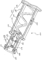
本明細書において、「前(または後)」なる用語は、穿刺要素が穿刺のために移動する方向を基準にして用いる。また、「上(または下)」なる用語は、各アームによって規定される面(即ち、これらがその延在方向に伸びる実質的に直線であると仮定した場合に、そのような直線を含む面)であって、穿刺要素の移動方向を含む面を基準にして、ランセットカバーが斜めに移動する方向を便宜的に「上」、それと逆の方向を「下」なる用語で表す(図1参照)。尚、これらの前後方向および上下方向の双方に垂直な方向であって、これらと一緒に直交座標系を構成する方向を左右方向とも呼ぶ。 In this specification, the term “front (or rear)” is used with reference to the direction in which the piercing element moves for piercing. In addition, the term “upper (or lower)” refers to the plane defined by each arm (ie, the plane containing such straight lines, assuming that they are substantially straight lines extending in the direction of extension). And the direction in which the lancet cover moves obliquely with respect to the plane including the moving direction of the puncture element is represented by the term “up” for convenience and the opposite direction is represented by the term “down” (see FIG. 1). ). Note that a direction perpendicular to both the front-rear direction and the up-down direction, which together form the orthogonal coordinate system, is also referred to as a left-right direction.
本発明のランセットアッセンブリは、上述または後述のランセット構造体とランセットホルダーとがいずれかの適当な形態で組み合わされた状態で供給するのが好ましい。例えば、ランセットホルダー内に、ランセット構造体の少なくとも一部分が挿入された状態である。より好ましい1つの態様では、ランセットホルダー内に、ランセット構造体のランセットが全部挿入されて、コネクターの突出部がトリガーに当接した状態(但し、スプリングは圧縮されていない状態)となるように組み合わせる。この場合、ランセットホルダーからランセット構造体を抜き出すことができないようになっているのが特に好ましい。別の態様では、ランセット構造体とランセットホルダーとが組み合わされておらず、この場合は、ランセットアッセンブリと言うより、むしろ、ランセット構造体とランセットホルダーとから構成されるランセットアッセンブリのキットと言える。 The lancet assembly of the present invention is preferably supplied in a state where the lancet structure and the lancet holder described above or below are combined in any suitable form. For example, at least a part of the lancet structure is inserted into the lancet holder. In a more preferable aspect, the lancet of the lancet structure is fully inserted into the lancet holder, and the connector protrusions are in contact with the trigger (however, the spring is not compressed). . In this case, it is particularly preferable that the lancet structure cannot be extracted from the lancet holder. In another aspect, the lancet structure and the lancet holder are not combined. In this case, rather than a lancet assembly, it can be said to be a kit of a lancet assembly composed of the lancet structure and the lancet holder.
第2の要旨において、本発明は、上述または後述の本発明のランセットアッセンブリを構成するランセットホルダーおよびランセット構造体を提供する。本発明は、そのようなランセット構造体を形成するためのランセットおよびエジェクターも更に提供する。このランセットホルダーおよびランセット構造体、ならびにランセットおよびエジェクターに関しては、上述または後述の本発明のランセットアッセンブリに関する説明が同様に当て嵌まる。 In a second aspect, the present invention provides a lancet holder and a lancet structure constituting the lancet assembly of the present invention described above or below. The present invention further provides lancets and ejectors for forming such lancet structures. Regarding the lancet holder and the lancet structure, and the lancet and the ejector, the description regarding the lancet assembly of the present invention described above or below applies similarly.
本発明のランセットアッセンブリでは、ランセット構造体をランセットホルダー内に挿入して、穿刺準備の完了状態にする場合、ランセットボディからランセットカバーが分離して、包囲されていた穿刺要素の先端部分がホルダー内で自動的に露出するので、従来のランセットアッセンブリにおいては必要であった樹脂カバーに対応するランセットカバーの除去操作が省略される。 In the lancet assembly of the present invention, when the lancet structure is inserted into the lancet holder so as to be ready for puncture, the lancet cover is separated from the lancet body, and the tip of the enclosed puncture element is in the holder. Therefore, the operation for removing the lancet cover corresponding to the resin cover, which was necessary in the conventional lancet assembly, is omitted.
図面において、参照番号は以下の要素を表す:
10…ランセットアッセンブリ、100…ランセットホルダー、102…後端部、
104…開口部、106…前端部、108…開口部、110…トリガー、
112…後端部、114…前端部、116…突出部、200…ランセット構造体、
202…エジェクター、204…ランセット、206…ベース、208…アーム、
210…スプリング、212…コネクター、214…ランセットカバー、
216…ランセットボディ、218…ノッチ部、220…穿刺要素、
222…前端部、223…鉤状部、224…後側、226…突出部、
228,230…突出部、232…先端部、234…前壁、236…テーパー部、
238…逆テーパー部、240…突出部、250…ステップ部、
252…ベース端部、254…傾斜面、256…前部、260,262…突出部、
270…凸部、272…凹部、274…凸部。In the drawings, reference numbers represent the following elements:
10 ... Lancet assembly, 100 ... Lancet holder, 102 ... Rear end,
104 ... opening, 106 ... front end, 108 ... opening, 110 ... trigger,
112 ... rear end, 114 ... front end, 116 ... protrusion, 200 ... lancet structure,
202 ... ejector, 204 ... lancet, 206 ... base, 208 ... arm,
210 ... spring, 212 ... connector, 214 ... lancet cover,
216 ... Lancet body, 218 ... Notch part, 220 ... Puncture element,
222 ... front end part, 223 ... hook-like part, 224 ... rear side, 226 ... projecting part,
228, 230 ... projecting portion, 232 ... tip portion, 234 ... front wall, 236 ... tapered portion,
238 ... reverse taper part, 240 ... protrusion part, 250 ... step part,
252 ... Base end, 254 ... Inclined surface, 256 ... Front, 260, 262 ... Projection,
270 ... convex part, 272 ... concave part, 274 ... convex part.
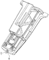
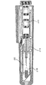
本発明のランセットアッセンブリ10を図1に模式的斜視図にて示す。ランセットアッセンブリ10は、ランセットホルダー100およびランセット構造体200により構成される。図示した態様では、ランセットホルダー100の内部空間内にランセット構造体200を矢印で示す方向に挿入する直前の状態を示す。尚、図1には、本明細書にて用いる用語「前」、「後」、「上」および「下」の方向(直交座標系を基準とする)を併せて示している。
A
ランセットホルダー100は、後端部102に開口部104を有し、前端部106にも開口部108(図1では見えず)を有する。開口部108に穿刺すべき箇所(例えば指先)をあてがっておくと、露出した穿刺要素の先端部が開口部108から飛び出す時、その箇所が穿刺される。ランセットホルダー100はトリガー110をその上側表面に有する。トリガー110は、その後端部112がランセットホルダー100の本体と一体になっており、前端部114は、ランセットホルダーの内部に(図1では下向きに)押し込むことができるようになっている(押し込む力を解放すると、元の形状に戻る)。ランセットホルダー100は、その上側壁の内側表面であって、トリガー110の前端部114のすぐ前方に突出部116(図1では見えず)を有する。この突出部116には、後述するランセットボディ216の突出部226が当接し、それによって、ランセットボディ216の前方への移動が阻止される。この阻止された状態は、トリガー110の前端部114を押し込むことによって解除できる。
The
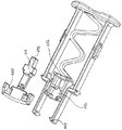
図2に、図1に示したランセット構造体200を、裏表を逆にした状態で(即ち、上下を逆転させた状態で)斜視図にて模式的に示す。ランセット構造体200は、エジェクター202およびランセット204から構成されている。エジェクター202は、ベース206を有し、その両側にアーム208が取り付けられている。図示するように、一対のアームの間にスプリングが存在するのが好ましいが、アームの数は、1つであっても、3つ以上であってもよい。これらのアームの間にスプリング210が配置され、その一端がベース206に取り付けられている。スプリング210の他方の端部にはコネクター212が取り付けられている。上述のように、ベース206、アーム208、スプリング210およびコネクター212は、一体に形成されているのが好ましい。例えば、樹脂を射出成形することにより形成できる。
FIG. 2 is a perspective view schematically showing the
ランセット204は、ランセットボディ216およびランセットカバー214から構成され、これらは、ノッチ部(V字状窪み部)としての弱化部分218によって接続されている。ランセット204は、穿刺要素220を更に有して成り、穿刺要素220の先端部は、ランセットカバー214によって包囲されている。穿刺要素220の後部はランセットボディ216内に存在する。図示した態様では、穿刺要素220の一部分が、ランセットボディ216とランセットカバー214との間で露出している。尚、別の態様では、弱化部分が存在せずにランセットボディとランセットカバーとが独立した部材として離間していてもよい。
The
図から理解できるように、アーム208の前方にランセットカバー214が位置し、図示した態様ではアーム208の前端部222は、ランセットカバー214の後側224に当接している。別の態様では、当接せずに(即ち、接触せずに)近接している状態であってもよく、この態様でも、後述するようにランセットボディ216の前方への移動が停止した後に、アーム208を更に前方に移動することによって、アーム208の前端部222は、ランセットカバー214の後側224に当接することになる。
As can be understood from the drawing, the
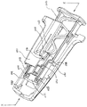
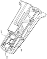
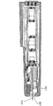
上述のように、ランセット構造体200をランセットホルダー100内に挿入した状態を図3に斜視図にて模式的に示す。尚、ランセットホルダー100の内部の様子が理解できるように、ランセットホルダーの下側半分および上側の半分の後半部のみを残して他の部分を切除した状態で示している。図1の状態からランセット構造体200を挿入すると、ランセットボディ216の突出部226がランセットホルダー100のトリガー110の前方の上側内壁に設けた突出部116に当接する。
As described above, the state in which the
図示した態様では、ランセットホルダーの内壁の側方に左右方向の幅が先広がりのテーパー状の突出部228が設けられ、ランセット構造体200を挿入する過程で、各アーム208の途中に設けた逆テーパー状の(即ち、先細りの)突出部230が突出部228を乗り越えて前進できるようになっている。突出部228は、突出部230がそれを乗り越えたときに突出部226が突出部116に丁度当接するように配置するのが好ましい。
In the illustrated embodiment, a
その結果、そのような当接状態に達する時に、スナップ感が感じられるのでアッセンブリの組立者または使用者にそのような状態に達したことが分かるので好都合である。このような乗り越えは、ランセット構造体およびランセットホルダーを、特にこれらの突出部を樹脂で形成してその弾性を利用することによって可能となる。また、図から明らかなように、上述のようなテーパー状とすることによって、突出部230が突出部228を一旦乗り越えると、突出部230が突出部228を乗り越えて後方に移動することは実質的に不可能となる。その結果、ランセットアッセンブリを組み立てたまたは使用した後で、アッセンブリを分解する(即ち、ランセット構造体をランセットホルダーから引き抜く)ことは実質的に不可能となり、アッセンブリの再使用、誤操作が回避され、安全が確保されるので好都合である。
As a result, a sense of snap is felt when such an abutting state is reached, which is advantageous because the assembly assembler or user knows that such a state has been reached. Such overcoming can be achieved by using the elasticity of the lancet structure and the lancet holder, in particular, by forming these protrusions with resin. Further, as is apparent from the drawing, by adopting the taper shape as described above, once the protruding
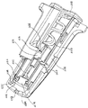
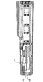
その後、ランセット構造体200を更に挿入しようとして、ランセット構造体200を前方に押すようにベース206に力を加えた状態を図4に示す。図3と比較すると明らかなように、図4では、スプリング210は圧縮可能であるので、ベース206は前方に移動しており、アーム208も前方に移動しているが、ランセットボディ216は、突出部116との当接状態のために前方に移動できないのでランセットボディ216の位置は図3の場合と同じである。
Thereafter, a state in which a force is applied to the base 206 so as to push the
アーム208の前端部222は、ランセットカバー214の後側224に当接しているので、図3の状態からランセット構造体200を更に押し込むと、アーム208はランセットカバー214を前方に移動させようとする力をランセットカバー214に加える。他方、ランセットボディ216は、突出部116と226との当接状態のために前方に移動することができない。その結果、ランセットカバー214とランセットボディ216との間にこれらを引き離そうとする力が作用することになる。その結果、図4に示すように、ランセットカバー214とランセットボディ216とが引き離され、穿刺要素220の先端部232が露出する。尚、ランセットボディおよびランセットカバーが独立した部材である態様では、ランセットボディからランセットカバーが遠ざかり、最終的に穿刺要素の先端部が露出する。
Since the
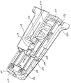
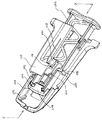
その後、図4に示す状態から、ランセット構造体200を更に挿入しようとして、ランセット構造体200を前方に押すようにベース206に力を加えた状態を図5に斜視図にて模式的に示す。図4と比較すると明らかなように、アーム208は前方に移動するが、ランセットボディ216は、その突出部226と突出部116との当接状態のために前方に移動できない。従って、ランセットボディ216の位置は変わっていない。しかしながら、スプリングは圧縮可能であるので、ベース206は更に前方に移動し、ランセットホルダーの後端部の開口部に設けたステップ250にベースの両端部252が当接し、それ以上の挿入はできないようになっている。尚、図示した態様では、突出部226はコネクター212に設けられているが、突出部は、スプリング210に設けても、あるいはランセットボディ216に設けてもよい。
Thereafter, from the state shown in FIG. 4, a state in which force is applied to the base 206 so as to push the
例えば図3および図4から容易に理解できるように、本発明のランセットアッセンブリにおいて、アームの前端部は、ランセットカバーに係合できるようにこれらが構成されているのが好ましい。より具体的には、アーム208の前端部222は、内側に屈曲した鉤状部(またはL字状部)223を有し、ランセットカバー214はその鉤状部に係合できる部分225を側方に規定する。図示した態様では、そのような部分は、鉤状部223が嵌り込む相補的な形状225を規定する(図8参照)。このように、アームの前端部がランセットカバーに係合することによって、ランセットカバー214は、それから穿刺要素220が分離した後であっても、係合関係によってアーム208の前端部222とランセットカバー214との当接状態が確保される。その結果、穿刺要素の先端部232が一旦露出した図4に示した状態において、例えば不用意にベース206を押し込むのを止めてスプリング210の作用によってアーム208が後退する場合であっても、ランセットカバー214もアームと208一緒に後退できる。このように係合関係が確保できない場合には、アームが後退した場合に、ランセットカバーが、フリーな状態となって、その後にアームを前進させた時にアーム208の前端部222とランセットカバー214との当接状態の確保が容易ではないことがある。尚、アームの前端部がランセットカバーに係合できるのであれば、鉤状部以外の形態であってもよいことは明らかである。
For example, as can be easily understood from FIGS. 3 and 4, in the lancet assembly of the present invention, it is preferable that the front end portion of the arm is configured to be able to engage with the lancet cover. More specifically, the
本発明のランセットアッセンブリにおいて、特に着目すべき点は、ランセットホルダーはその前端部の側方内壁にガイド手段を有し、ランセットカバーはガイド手段にガイドされる被ガイド手段を有し、ガイド手段および被ガイド手段が協働することによって、分離したランセットカバーが前方に移動するアームにより前方に移動するに際して、ランセットカバーが前方斜め(斜め上または斜め下)方向に移動する点である。より具体的には、ランセットホルダーは、その前端部の側方内壁に、前方斜め方向に延在するスライド部をガイド手段として有し、ランセットカバーは、スライド部上を滑動する部分、例えば突出部を被ガイド手段として有する。 In the lancet assembly of the present invention, it should be particularly noted that the lancet holder has guide means on the side inner wall of the front end portion thereof, and the lancet cover has guided means guided by the guide means. When the guided lancet cooperates, the separated lancet cover moves forward in the oblique (upward or obliquely downward) direction when it moves forward by the arm that moves forward. More specifically, the lancet holder has a slide portion extending in a front oblique direction as a guide means on a side inner wall of the front end portion thereof, and the lancet cover is a portion that slides on the slide portion, for example, a protruding portion. As guided means.
図5に示す態様では、分離されたランセットカバー214がアーム208に押されて、その結果、ランセットホルダーの前壁234の内側に当接している。ランセットカバー214の側方には、前方に向かって上下方向の幅が先細りとなるテーパー部236が被ガイド手段として設けられている。また、ランセットホルダー100の前端部の内側の側壁には前方に先広がり形状のテーパー部(即ち、逆テーパー部)238がガイド手段として設けられ、このガイド手段としての逆テーパー部238傾斜面は254をスライド部として有する(図4参照)。これらのテーパー部は、傾斜面254上をテーパー部236の下面が滑動するようになっている。その結果、アーム208によって前方に押されるランセットカバー214のテーパー部236は、逆テーパー部238の傾斜面254を上ることになる。即ち、ランセットカバー214は、アーム208によって前方斜め上方向に移動してランセットカバーの前壁234に当接している。この当接状態は、アーム208に押された状態を維持することによって確保される。
In the embodiment shown in FIG. 5, the separated
このようなランセットカバーの斜め方向の移動は、1つの態様では、例えば、図14に示すように、スライド部は、ランセットホルダーの前端部の側方内壁に設けた、前方斜め方向に延在するスライド面を有する凸部または傾斜プレート270の形態であり、被スライド部は、ランセットカバーの側方部またはそれに設けた凸部(図15の凸部と同様のもの)である態様においても達成できる。
For example, as shown in FIG. 14, the sliding portion extends in the diagonally forward direction provided on the side inner wall of the front end portion of the lancet holder. It is a form of the convex part which has a slide surface, or the
更に別の態様では、例えば、図15に示すように、スライド部は、ランセットホルダーの前端部の側方内壁に設けた、前方斜め方向に延在するスライド面を有する凹部272の形態であり、被スライド部は、ランセットカバーに設けた凸部274であり、この凸部が凹部に嵌り込んでガイドされる態様においても達成できる。
In still another aspect, for example, as shown in FIG. 15, the slide portion is in the form of a
ランセットカバー214の上述のような斜め方向の移動は、いずれの場合であっても、露出した穿刺要素の先端部232がランセットホルダー100の前端の開口部108を通って指先等を穿刺するのを確保できる程度に十分である必要がある。即ち、穿刺要素の先端部232が露出したランセットボディ216が発射される場合に、先端部232の移動方向に沿ってその前方にはランセットカバー214が存在せず、従って、ランセットカバー214は先端部232と接触することは無く、先端部の移動を邪魔しない(先端部232の軌道上にはランセットカバー214は存在しない)。この意味で先に「直接」なる用語を使用している。
In any case, the
このように、ランセットカバー214がランセットホルダー100の前端部に保持されることによって、穿刺の準備が完了する。この場合、先に説明した場合と同様に、ランセットホルダーの側方内壁に左右方向の幅が先広がりのテーパー状の突出部240が(上述の突出部228と前端部との間に)設けられ、ランセット構造体200を挿入する過程で、アーム208の途中に設けた逆テーパー状の突出部230がこの突出部240を乗り越えることができるようになっている。突出部240は、突出部230がそれを乗り越えた時にランセットカバー214がランセットホルダーの前壁234の内側に丁度当接するように配置するのが好ましい。
In this way, the
その結果、そのような当接状態に達する時に、スナップ感が感じられるので使用者は穿刺準備が完了したことを感知できるので好都合である。このような乗り越えは、ランセット構造体およびランセットホルダーを樹脂で形成してその弾性を利用することによって可能となる。また、図から明らかなように、テーパー状とすることによって、突出部230が突出部240を一旦乗り越えると、突出部230が突出部240を乗り越えて後方に移動することは実質的に不可能となる。その結果、ランセットアッセンブリを使用した後で、アッセンブリを分解することは実質的に不可能となり、アッセンブリの再使用、誤操作が回避され、安全が確保される。
As a result, when such a contact state is reached, a sense of snap is felt, which is advantageous because the user can sense that the puncture preparation is complete. Such overcoming can be achieved by forming the lancet structure and the lancet holder from resin and utilizing their elasticity. Further, as is apparent from the drawing, by forming the taper, once the
図5に示した状態で穿刺準備が完了している。明らかなように、ランセットボディ216は、トリガー110前方に位置する突出部116に当接した状態のままである。従って、この状態からトリガー110の前端部114をランセットホルダーの内部に押し込んで突出部116と226の当接状態を解除すると、圧縮されたスプリング210が元の形状に戻ろうとすることによって、先端部が露出した穿刺要素を有するランセットボディ216が前方に発射され、ランセットカバー214によって邪魔されることなく先端部232が開口部108から突出することができ、その結果、穿刺できる。このように先端部分が飛び出した様子を図6に斜視図にて模式的に示している。尚、スプリング210は圧縮されて拘束されている状態から、その拘束が瞬時に無くなるので、図6では、図1に示す元の形状よりも延びた状態となっている。
The puncture preparation is completed in the state shown in FIG. As is apparent, the
穿刺要素の先端部232が開口部108から突出する時、所定部位を穿刺すると共に、ランセットボディ216のその前部256は、ランセットホルダーの前壁に衝突するので、延びたスプリング210は、元の形状に向かって戻ろうとし、その結果、最終的には、図2に示す状態と同様の形状に戻る。その様子を図7に示している。スプリング210が元の形状に戻った状態では、穿刺要素の先端部232はランセットホルダーの開口部108から十分な距離で離れて内側に位置する(図7では、ランセットカバー214の下に位置するので見えず)ので、開口部108から露出した穿刺要素の先端部232にランセットホルダー100の外部から触れることは実質的に回避できる。
When the
図7に示した状態は、ランセットアッセンブリを使用して穿刺が終了した状態であるので、図7の状態のままで処分することができる。先に説明したように、テーパー形状の突出部230および240を設けることによって図7の状態からランセット構造体200をランセットホルダー100から抜き出すことができないので、図7の状態で廃棄等の処分を実施する場合でも、穿刺要素の先端部が露出することはないので、意図しない先端部への接触を回避でき、廃棄時の安全性が向上する。
The state shown in FIG. 7 is a state where the puncture is completed using the lancet assembly, and can be disposed in the state shown in FIG. As described above, since the
好ましい態様では、図示するように、各アーム208は、ガイドピンとしての突出部260を有して成る。このガイドピンは、ランセットホルダーの内側表面内に設けた、穿刺方向に伸びるチャンネルと協働するように構成されている。即ち、ランセット構造体をランセットホルダー内に挿入する時に、ガイドピンがチャンネル内で滑動し、その結果、アームがランセットホルダー内で円滑に前方に移動し、挿入が円滑になる。即ち、ガイドピンは、ランセットホルダー内におけるアームの前方への移動を誘導する。
In a preferred embodiment, as shown, each
別の好ましい態様では、図示するように、コネクター212は、ガイドピンとしての突出部262を有して成る。このガイドピンは、ランセットホルダーの内側表面内に設けた、穿刺方向に伸びる別のチャンネルと協働する。即ち、ランセット構造体をランセットホルダー内に挿入する時に、ガイドピンがチャンネル内で滑動し、その結果、コネクター212、即ち、結合しているランセットボディ216がランセットホルダー内で円滑に前方に移動し、挿入が円滑になる。更に、このチャンネルは、ランセットボディ216が発射されて穿刺し、その後、穿刺要素の先端部が引っ込む過程でランセットボディ216がランセットホルダー内で穿刺方向に沿って前後に移動するのを円滑にする。即ち、ガイドピンは、露出した穿刺要素を有するランセットボディの発射を誘導する。
In another preferred embodiment, as shown, the
本発明のランセット構造体は、エジェクター202およびランセット204から構成され、これらはコネクター212を介して一体に接続されている。これらの接続には、いずれの適当な方法を用いてもよい。例えば、相互に嵌め込むことができる凹部(雌部または鍵穴部)および凸部(雄部または鍵部)の組(好ましくはこれらが相補的形状を有する)の一方をコネクター212に形成し、他方をランセットボディ216に形成することによって実施する。この凹部および凸部の形成に際しては、ランセットボディとコネクターは係合して前後方向には分離できないが、上下方向に嵌め込む(または分離する)ことができるように凹部をコネクターに、そして凸部をランセットボディに(あるいはこの逆に)形成する。
The lancet structure of the present invention includes an
このような接続の一例を図8に示す。図8において、ランセットボディ216は全体としての凸部270を有し、コネクター212は、その凸部を嵌め込むことができる凹部272を有する。容易に理解できるように、凸部270を下方に移動して凹部272に嵌め込むと、前後方向の力に対しては、コネクター212とランセットボディ216は分離せず、これらは一体として挙動する。しかしながら、上下方向に力が作用すると、コネクター212とランセットボディ216は容易に分離できる。このような接続方法を採用すると、ランセットとエジェクターとを別々に成形して一体に組み合わせることができるので好都合である。
An example of such a connection is shown in FIG. In FIG. 8, the
尚、本明細書において、テーパー部の「先細り」または「先広がり」とは、前方に向かって(図1の「前」に向かう方向)に見た場合を基準とし、テーパー部の幅(前方向に対して垂直な寸法)が狭くなっている場合を「先細り」と呼び、広がっている場合には「先広がり」と呼ぶ。また、逆テーパー部とは、その部分が、それに対応するテーパー部と逆のテーパー形状を有することを意味する。即ち、一方が先細りテーパー形状であり、他方が先広がりテーパー形状を有する場合、前者をテーパー形状と呼ぶ場合、後者を逆テーパー形状と呼び、逆に、後者をテーパー形状と呼ぶ場合、前者を逆テーパー形状と呼ぶ。また、「テーパー状」についても同様である。 In the present specification, “tapering” or “broadening” of the tapered portion is based on the case of looking forward (in the direction toward “front” in FIG. 1), and the width of the tapered portion (frontward). When the dimension (perpendicular to the direction) is narrow, it is called “tapering”, and when it is widening, it is called “pointing forward”. Moreover, a reverse taper part means that the part has a taper shape reverse to the taper part corresponding to it. That is, when one has a tapered shape and the other has a tapered shape, when the former is called a tapered shape, the latter is called a reverse tapered shape, and conversely, when the latter is called a tapered shape, the former is reversed. It is called a taper shape. The same applies to the “tapered shape”.
本発明のランセットアッセンブリによる穿刺は、次のようにして起こる:
1)最初に、ランセット構造体200をランセットホルダー100の後端の開口部104からその中に挿入する(図1の矢印で示す状態)。Puncture with the lancet assembly of the present invention occurs as follows:
1) First, the
2)ランセット構造体200をランセットホルダー100内で前方に移動させ、ランセットボディ216に設けた突出部226の前端を、ランセットホルダー100のトリガー110の前方に設けたストッパーとしての突出部116の後端に当接させ、それによって、ランセット204の移動を止め、それ以上前方には進まない状態とする、即ち、ランセットをその前方への移動に対して拘束する(図3の状態)。
2) The
3)ランセット204を拘束した状態で、ベース206を更に前方に押し込み、無負荷時の状態からスプリング210の圧縮を開始して、スプリング210がエネルギーを蓄えるようにする(図3と図4の間の状態)。
3) With the
4)ベース206をランセットホルダー100内に更に押し込み、アーム208がランセットカバーを前方に押すことによって、ランセットカバー214とランセットボディ216との接合部であるノッチ部218(弱化部分として機能する)にて破壊が生じ、ランセットカバー214とランセットボディ216が分離する。その後、アーム208を更に前方に進めることによって、穿刺要素の先端部232が露出する(図4の状態)。
4) When the
5)アーム208を更に前方に進めると、ランセットカバー214が前方斜め上方向に移動し、ランセットホルダー100の前端部の壁234の内側に当接した状態で保持される(図5の状態)。
5) When the
6)次に、ランセットホルダーの前方開口部108に採血対象部位(例えば指先)に押し当てる;
6) Next, press against the blood collection target site (for example, fingertip) against the
7)トリガー110の前方端部114付近をランセットホルダー100の内部に向かうように押し込むことによって、突出部116と突出部226との当接状態が解放され、圧縮状態のスプリング210が瞬時に伸長することによってランセットボディ216を発射し、穿刺要素の先端部232が開口部108から飛び出し、穿刺が行われる(図6の状態)。
7) By pushing the vicinity of the
8)その後、スプリング210が元の形状に戻り、穿刺要素の先端部232が開口部108から十分距離引っ込んだ状態となる(図7の状態)。
8) Thereafter, the
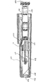
本発明のランセット構造体とランセットホルダーとの位置関係またはそれらを構成する各要素間の位置関係の理解を助けるため、図3〜7の状態におけるランセットホルダーの中央線(線X−X)に沿った模式的断面図をそれぞれ図9〜13に示す。 In order to facilitate understanding of the positional relationship between the lancet structure of the present invention and the lancet holder or the positional relationship between the elements constituting the lancet structure, along the center line (line XX) of the lancet holder in the state of FIGS. 9 to 13 are schematic sectional views respectively.
図9は、図3の状態に対応する断面図である。図9では、ランセットボディ216の突出部226がランセットホルダー100のトリガー110の前方に位置する突出部116に当接している状態がわかる。V字形状のノッチ部218がランセットカバー214とランセットボディ216とを一体に結合している。
FIG. 9 is a cross-sectional view corresponding to the state of FIG. In FIG. 9, it can be seen that the
図10は、図4状態に対応する断面図である。図10では、ランセットカバー214がランセットボディ216から分離され、穿刺要素の先端部232が露出した状態となっている。また、図9と比べてスプリング210が圧縮されている様子が分かる。
FIG. 10 is a cross-sectional view corresponding to the state of FIG. In FIG. 10, the
図11は、図5状態に対応する断面図である。図11では、ランセットカバー214がランセットホルダーの前端部の壁の内側に当接した状態となっている。図から分かるように、ランセットカバーは、図10の状態と比べると、前方に移動しているだけでなく、上方向にも移動している。即ち、前方斜め上方向に移動している。これは、ランセットホルダーの前端部の内側に設けた逆テーパー部238の傾斜面254に沿ってランセットカバーの側方に位置するテーパー部236が移動するからである。
FIG. 11 is a cross-sectional view corresponding to the state of FIG. In FIG. 11, the
図12は、図6状態に対応する断面図である。図12では、穿刺要素の先端部232がランセットホルダー100の前端開口部108から飛び出した状態となっている。図から分かるように、ランセットカバー214は、前方斜め上方向に移動した後なので、穿刺要素の移動を全く妨げない。
FIG. 12 is a cross-sectional view corresponding to the state of FIG. In FIG. 12, the
図13は、図7状態に対応する断面図である。図13では、穿刺要素の先端部232がランセットホルダー100の前端開口部108から十分距離内側に引っ込んだ状態となっている。図から分かるように、開口部108から穿刺要素の先端部232に触れることは全く容易でなく、意図して触れようとしない限り、実質的には不可能である。
FIG. 13 is a cross-sectional view corresponding to the state of FIG. In FIG. 13, the
上述のような本発明のランセットアッセンブリは、より簡便な採血手段を提供するものである。
The lancet assembly of the present invention as described above provides a simpler blood collection means.
Claims (28)
ランセット構造体は、エジェクターおよびランセットから構成され、
エジェクターは、アーム、スプリング、ならびにアームおよびスプリングが取り付けられたベースを有して成り、スプリングは、その前端にコネクターを有し、また、その後端はベースに接続され、
ランセットは、ランセットボディ、ランセットカバーおよび穿刺要素を有して成り、穿刺要素はランセットボディおよびランセットカバーにまたがってこれらの中に存在し、穿刺要素の先端部はランセットカバーによって包囲され、
ランセットボディは、コネクターに接続され、
ランセットホルダーは、穿刺要素の先端部が通過する開口部をその前端部に有し、
ランセット構造体をランセットホルダーに挿入してベースをコネクターに向かって相対的に移動させてスプリングを圧縮すると、ランセットカバーが穿刺要素から分離して、包囲されていた穿刺要素の先端部が露出し、
ランセットカバーは、アームの前方に位置し、
アームの前端部がランセットカバーの後側に当接した状態を維持しつつ、ベースをコネクターに向かって相対的に移動させてスプリングを圧縮すると、弱化部分にてランセットカバーがランセットボディから分離
することを特徴とするランセットアッセンブリ。A lancet assembly comprising a lancet structure and a lancet holder for holding the lancet structure,
The lancet structure consists of an ejector and a lancet,
The ejector comprises an arm, a spring, and a base to which the arm and the spring are attached, the spring having a connector at its front end, and its rear end connected to the base,
The lancet has a lancet body, a lancet cover and a puncture element, the puncture element lies in and spans the lancet body and the lancet cover, the tip of the puncture element is surrounded by the lancet cover,
The lancet body is connected to the connector,
The lancet holder has an opening at its front end through which the tip of the puncture element passes,
When the lancet structure is inserted into the lancet holder and the base is moved relative to the connector to compress the spring, the lancet cover is separated from the puncture element, and the tip of the enclosed puncture element is exposed ,
The lancet cover is located in front of the arm,
While maintaining the state where the front end of the arm is in contact with the rear side of the lancet cover, the lancet cover is separated from the lancet body at the weakened part by moving the base relative to the connector and compressing the spring. <Br A lancet assembly characterized by:
ランセットカバーは、ガイド手段にガイドされる被ガイド手段を有し、
ガイド手段および被ガイド手段が協働することによって、分離したランセットカバーが前方に移動するアームにより前方に移動することにより、ランセットカバーが前方斜め(斜め上または斜め下)方向に移動することを特徴とする請求項6に記載のランセットアッセンブリ。The lancet holder has guide means on the side inner wall of its front end,
The lancet cover has guided means guided by the guide means,
By the cooperation of the guide means and the guided means, the separated lancet cover is moved forward by the arm that moves forward, so that the lancet cover moves in the diagonally forward (diagonally upward or obliquely downward) direction. The lancet assembly according to claim 6 .
ランセットカバーは、スライド部上を滑動する部分(例えば突出部)を被ガイド手段として有することを特徴とする請求項7に記載のランセットアッセンブリ。The lancet holder has a slide part extending in a diagonally forward direction as a guide means on the side inner wall of the front end part thereof,
8. The lancet assembly according to claim 7 , wherein the lancet cover has a portion (for example, a protruding portion) that slides on the slide portion as guided means.
ランセットホルダーは、その前端部の側方内壁に、スライド部として該テーパー部が滑動する逆テーパー部を有することを特徴とする請求項8に記載のランセットアッセンブリ。The lancet cover has, on the side, a tapered portion whose width decreases toward the front as a sliding portion,
9. The lancet assembly according to claim 8 , wherein the lancet holder has a reverse tapered portion on which a tapered portion slides as a sliding portion on a side inner wall of a front end portion thereof.
被スライド部は、ランセットカバーの側方に設けた凸部であることを特徴とする請求項8に記載のランセットアッセンブリ。The slide part is a convex part or a concave part provided on the side inner wall of the front end part of the lancet holder, and having a slide surface extending in a front oblique direction,
9. The lancet assembly according to claim 8 , wherein the sliding portion is a convex portion provided on a side of the lancet cover.
コネクターは突出部を有して成り、
スプリングの圧縮に際して、コネクターの突出部はランセットホルダーの突出部に当接して、それによって、コネクターの前方への移動が阻止され、
トリガーはそのような当接状態を解除する請求項1〜16のいずれかに記載のランセットアッセンブリ。The lancet holder has a trigger for firing the lancet body from which the tip of the puncture element is exposed, and a protrusion (or a locking part) located in front of the trigger.
The connector comprises a protrusion and
During the compression of the spring, the protrusion of the connector abuts the protrusion of the lancet holder, thereby preventing the connector from moving forward,
The lancet assembly according to any one of claims 1 to 16 , wherein the trigger releases such a contact state.
スプリングは突出部を有して成り、
スプリングの圧縮に際して、スプリングの突出部はランセットホルダーの突出部に当接して、それによって、コネクターの前方への移動が阻止され、
トリガーはそのような当接状態を解除する請求項1〜16のいずれかに記載のランセットアッセンブリ。The lancet holder has a trigger for firing the lancet body from which the tip of the puncture element is exposed, and a protrusion located in front of the trigger.
The spring has a protrusion,
During compression of the spring, the protrusion of the spring contacts the protrusion of the lancet holder, thereby preventing the connector from moving forward,
The lancet assembly according to any one of claims 1 to 16 , wherein the trigger releases such a contact state.
ランセットボディは突出部を有して成り、
スプリングの圧縮に際して、ランセットボディの突出部はランセットホルダーの突出部に当接して、それによって、コネクターの前方への移動が阻止され、
トリガーはそのような当接状態を解除する請求項1〜16のいずれかに記載のランセットアッセンブリ。The lancet holder has a trigger for firing the lancet body from which the tip of the puncture element is exposed, and a protrusion located in front of the trigger.
The lancet body has a protrusion,
During the compression of the spring, the protrusion of the lancet body abuts the protrusion of the lancet holder, thereby preventing the connector from moving forward,
The lancet assembly according to any one of claims 1 to 16 , wherein the trigger releases such a contact state.
ランセットホルダーは、該ガイドピンを誘導するチャンネル部を内壁に有して成る請求項1〜19のいずれかに記載のランセットアッセンブリ。The arm has a guide pin,
The lancet assembly according to any one of claims 1 to 19 , wherein the lancet holder has a channel portion for guiding the guide pin on an inner wall.
ランセットホルダーは、該ガイドピンを誘導するチャンネル部を内壁に有して成る請求項1〜20のいずれかに記載のランセットアッセンブリ。The connector comprises a guide pin,
21. The lancet assembly according to any one of claims 1 to 20 , wherein the lancet holder has a channel portion for guiding the guide pin on an inner wall.
Applications Claiming Priority (3)
| Application Number | Priority Date | Filing Date | Title |
|---|---|---|---|
| JP2004146321 | 2004-05-17 | ||
| JP2004146321 | 2004-05-17 | ||
| PCT/JP2005/008899 WO2005110225A1 (en) | 2004-05-17 | 2005-05-16 | Lancet assembly |
Publications (2)
| Publication Number | Publication Date |
|---|---|
| JPWO2005110225A1 JPWO2005110225A1 (en) | 2008-03-21 |
| JP4635002B2 true JP4635002B2 (en) | 2011-02-16 |
Family
ID=35393943
Family Applications (1)
| Application Number | Title | Priority Date | Filing Date |
|---|---|---|---|
| JP2006513589A Expired - Fee Related JP4635002B2 (en) | 2004-05-17 | 2005-05-16 | Lancet assembly |
Country Status (7)
| Country | Link |
|---|---|
| US (1) | US7883523B2 (en) |
| EP (1) | EP1747756A4 (en) |
| JP (1) | JP4635002B2 (en) |
| KR (1) | KR20070011514A (en) |
| CN (1) | CN100443049C (en) |
| CA (1) | CA2567498A1 (en) |
| WO (1) | WO2005110225A1 (en) |
Cited By (1)
| Publication number | Priority date | Publication date | Assignee | Title |
|---|---|---|---|---|
| JP2012508633A (en) * | 2008-11-17 | 2012-04-12 | オーウェン マンフォード リミテッド | Skin puncture device |
Families Citing this family (68)
| Publication number | Priority date | Publication date | Assignee | Title |
|---|---|---|---|---|
| US6391005B1 (en) | 1998-03-30 | 2002-05-21 | Agilent Technologies, Inc. | Apparatus and method for penetration with shaft having a sensor for sensing penetration depth |
| US8641644B2 (en) | 2000-11-21 | 2014-02-04 | Sanofi-Aventis Deutschland Gmbh | Blood testing apparatus having a rotatable cartridge with multiple lancing elements and testing means |
| AU2002348683A1 (en) | 2001-06-12 | 2002-12-23 | Pelikan Technologies, Inc. | Method and apparatus for lancet launching device integrated onto a blood-sampling cartridge |
| ES2336081T3 (en) | 2001-06-12 | 2010-04-08 | Pelikan Technologies Inc. | SELF-OPTIMIZATION PUNCTURE DEVICE WITH MEANS OF ADAPTATION TO TEMPORARY VARIATIONS IN CUTANEOUS PROPERTIES. |
| US7981056B2 (en) | 2002-04-19 | 2011-07-19 | Pelikan Technologies, Inc. | Methods and apparatus for lancet actuation |
| US8337419B2 (en) | 2002-04-19 | 2012-12-25 | Sanofi-Aventis Deutschland Gmbh | Tissue penetration device |
| US7041068B2 (en) | 2001-06-12 | 2006-05-09 | Pelikan Technologies, Inc. | Sampling module device and method |
| ATE485766T1 (en) | 2001-06-12 | 2010-11-15 | Pelikan Technologies Inc | ELECTRICAL ACTUATING ELEMENT FOR A LANCET |
| US9226699B2 (en) | 2002-04-19 | 2016-01-05 | Sanofi-Aventis Deutschland Gmbh | Body fluid sampling module with a continuous compression tissue interface surface |
| US9427532B2 (en) | 2001-06-12 | 2016-08-30 | Sanofi-Aventis Deutschland Gmbh | Tissue penetration device |
| US9795747B2 (en) | 2010-06-02 | 2017-10-24 | Sanofi-Aventis Deutschland Gmbh | Methods and apparatus for lancet actuation |
| US8221334B2 (en) | 2002-04-19 | 2012-07-17 | Sanofi-Aventis Deutschland Gmbh | Method and apparatus for penetrating tissue |
| US7892183B2 (en) | 2002-04-19 | 2011-02-22 | Pelikan Technologies, Inc. | Method and apparatus for body fluid sampling and analyte sensing |
| US8702624B2 (en) | 2006-09-29 | 2014-04-22 | Sanofi-Aventis Deutschland Gmbh | Analyte measurement device with a single shot actuator |
| US7226461B2 (en) | 2002-04-19 | 2007-06-05 | Pelikan Technologies, Inc. | Method and apparatus for a multi-use body fluid sampling device with sterility barrier release |
| US7229458B2 (en) | 2002-04-19 | 2007-06-12 | Pelikan Technologies, Inc. | Method and apparatus for penetrating tissue |
| US7901362B2 (en) | 2002-04-19 | 2011-03-08 | Pelikan Technologies, Inc. | Method and apparatus for penetrating tissue |
| US9314194B2 (en) | 2002-04-19 | 2016-04-19 | Sanofi-Aventis Deutschland Gmbh | Tissue penetration device |
| US8784335B2 (en) | 2002-04-19 | 2014-07-22 | Sanofi-Aventis Deutschland Gmbh | Body fluid sampling device with a capacitive sensor |
| US7674232B2 (en) | 2002-04-19 | 2010-03-09 | Pelikan Technologies, Inc. | Method and apparatus for penetrating tissue |
| US7331931B2 (en) | 2002-04-19 | 2008-02-19 | Pelikan Technologies, Inc. | Method and apparatus for penetrating tissue |
| US9248267B2 (en) | 2002-04-19 | 2016-02-02 | Sanofi-Aventis Deustchland Gmbh | Tissue penetration device |
| US7976476B2 (en) | 2002-04-19 | 2011-07-12 | Pelikan Technologies, Inc. | Device and method for variable speed lancet |
| US7232451B2 (en) | 2002-04-19 | 2007-06-19 | Pelikan Technologies, Inc. | Method and apparatus for penetrating tissue |
| US8360992B2 (en) | 2002-04-19 | 2013-01-29 | Sanofi-Aventis Deutschland Gmbh | Method and apparatus for penetrating tissue |
| US7909778B2 (en) | 2002-04-19 | 2011-03-22 | Pelikan Technologies, Inc. | Method and apparatus for penetrating tissue |
| US7547287B2 (en) | 2002-04-19 | 2009-06-16 | Pelikan Technologies, Inc. | Method and apparatus for penetrating tissue |
| US7297122B2 (en) | 2002-04-19 | 2007-11-20 | Pelikan Technologies, Inc. | Method and apparatus for penetrating tissue |
| US7175642B2 (en) | 2002-04-19 | 2007-02-13 | Pelikan Technologies, Inc. | Methods and apparatus for lancet actuation |
| US8267870B2 (en) | 2002-04-19 | 2012-09-18 | Sanofi-Aventis Deutschland Gmbh | Method and apparatus for body fluid sampling with hybrid actuation |
| US8579831B2 (en) | 2002-04-19 | 2013-11-12 | Sanofi-Aventis Deutschland Gmbh | Method and apparatus for penetrating tissue |
| US8372016B2 (en) | 2002-04-19 | 2013-02-12 | Sanofi-Aventis Deutschland Gmbh | Method and apparatus for body fluid sampling and analyte sensing |
| US9795334B2 (en) | 2002-04-19 | 2017-10-24 | Sanofi-Aventis Deutschland Gmbh | Method and apparatus for penetrating tissue |
| US7491178B2 (en) | 2002-04-19 | 2009-02-17 | Pelikan Technologies, Inc. | Method and apparatus for penetrating tissue |
| US8574895B2 (en) | 2002-12-30 | 2013-11-05 | Sanofi-Aventis Deutschland Gmbh | Method and apparatus using optical techniques to measure analyte levels |
| EP1628567B1 (en) | 2003-05-30 | 2010-08-04 | Pelikan Technologies Inc. | Method and apparatus for fluid injection |
| EP1633235B1 (en) | 2003-06-06 | 2014-05-21 | Sanofi-Aventis Deutschland GmbH | Apparatus for body fluid sampling and analyte sensing |
| WO2006001797A1 (en) | 2004-06-14 | 2006-01-05 | Pelikan Technologies, Inc. | Low pain penetrating |
| EP1671096A4 (en) | 2003-09-29 | 2009-09-16 | Pelikan Technologies Inc | METHOD AND APPARATUS FOR AN IMPROVED SAMPLING INTERFERENCE DEVICE |
| US9351680B2 (en) | 2003-10-14 | 2016-05-31 | Sanofi-Aventis Deutschland Gmbh | Method and apparatus for a variable user interface |
| US7822454B1 (en) | 2005-01-03 | 2010-10-26 | Pelikan Technologies, Inc. | Fluid sampling device with improved analyte detecting member configuration |
| EP1706026B1 (en) | 2003-12-31 | 2017-03-01 | Sanofi-Aventis Deutschland GmbH | Method and apparatus for improving fluidic flow and sample capture |
| CA2567498A1 (en) * | 2004-05-17 | 2005-11-24 | Izumi-Cosmo Company, Limited | Lancet assembly |
| WO2006011062A2 (en) | 2004-05-20 | 2006-02-02 | Albatros Technologies Gmbh & Co. Kg | Printable hydrogel for biosensors |
| WO2005120365A1 (en) | 2004-06-03 | 2005-12-22 | Pelikan Technologies, Inc. | Method and apparatus for a fluid sampling device |
| US9775553B2 (en) | 2004-06-03 | 2017-10-03 | Sanofi-Aventis Deutschland Gmbh | Method and apparatus for a fluid sampling device |
| US7879059B2 (en) * | 2004-10-06 | 2011-02-01 | Izumi-Cosmo Company, Limited | Lancet assembly |
| US8652831B2 (en) | 2004-12-30 | 2014-02-18 | Sanofi-Aventis Deutschland Gmbh | Method and apparatus for analyte measurement test time |
| CA2622604A1 (en) * | 2005-09-29 | 2007-04-05 | Izumi-Cosmo Company, Limited | Lancet assembly and puncture device |
| GB0524604D0 (en) | 2005-12-02 | 2006-01-11 | Owen Mumford Ltd | Injection method and apparatus |
| GB2434103B (en) | 2006-01-12 | 2009-11-25 | Owen Mumford Ltd | Lancet firing device |
| CA2654377A1 (en) * | 2006-06-13 | 2007-12-21 | Izumi-Cosmo Company, Limited | Lancet assembly and pricking device |
| CN101466309B (en) * | 2006-06-13 | 2010-12-15 | 泉株式会社 | Lancet assembly |
| GB2440118A (en) * | 2006-07-18 | 2008-01-23 | Owen Mumford Ltd | Skin pricking device |
| JP4923109B2 (en) * | 2007-09-28 | 2012-04-25 | 泉株式会社 | Lancet assembly and lancing device |
| KR100932946B1 (en) | 2008-03-19 | 2009-12-21 | 홍관호 | Blood collector |
| WO2009126900A1 (en) | 2008-04-11 | 2009-10-15 | Pelikan Technologies, Inc. | Method and apparatus for analyte detecting device |
| US20100049233A1 (en) * | 2008-08-25 | 2010-02-25 | Abbott Diabetes Care Inc. | Lancet having integrated drive mechanism |
| US20100125294A1 (en) * | 2008-11-17 | 2010-05-20 | Shinichi Yasui | Lancet assembly |
| JP2010148694A (en) * | 2008-12-25 | 2010-07-08 | Nissei Plastics Ind Co | Puncture device |
| US9375169B2 (en) | 2009-01-30 | 2016-06-28 | Sanofi-Aventis Deutschland Gmbh | Cam drive for managing disposable penetrating member actions with a single motor and motor and control system |
| US8262685B2 (en) | 2009-03-27 | 2012-09-11 | Nipro Corporation | Disposable lancing device |
| US8965476B2 (en) | 2010-04-16 | 2015-02-24 | Sanofi-Aventis Deutschland Gmbh | Tissue penetration device |
| JP5514008B2 (en) | 2010-06-22 | 2014-06-04 | ニプロ株式会社 | Disposable puncture device |
| JP5753071B2 (en) * | 2011-12-20 | 2015-07-22 | 泉株式会社 | Lancet assembly and lancing device |
| USD749724S1 (en) * | 2014-09-02 | 2016-02-16 | Sterilance Medical (Suzhou) Inc. | Body of disposable safety lancet |
| USD818575S1 (en) * | 2015-12-08 | 2018-05-22 | Becton Dickinson France S.A.S. | Medical injector with enhanced grip |
| CN111419240B (en) * | 2020-04-21 | 2021-10-08 | 苏州施莱医疗器械有限公司 | Blood sampling pen convenient to needle-prick cap is unloaded |
Citations (3)
| Publication number | Priority date | Publication date | Assignee | Title |
|---|---|---|---|---|
| WO1996016599A1 (en) * | 1994-11-29 | 1996-06-06 | Apls Co., Ltd. | Lancet assembly |
| US6358265B1 (en) * | 2000-07-18 | 2002-03-19 | Specialized Health Products, Inc. | Single-step disposable safety lancet apparatus and methods |
| WO2003070099A1 (en) * | 2002-02-21 | 2003-08-28 | Facet Technologies, Llc | Blood analyzer and pricking device for use in blood analysis |
Family Cites Families (12)
| Publication number | Priority date | Publication date | Assignee | Title |
|---|---|---|---|---|
| DE8007991U1 (en) * | 1980-03-22 | 1981-04-09 | Clinicon Mannheim GmbH, 6800 Mannheim | Blood lancet device for drawing blood for diagnostic purposes |
| US4616649A (en) * | 1984-09-20 | 1986-10-14 | Becton, Dickinson And Company | Lancet |
| GB8710470D0 (en) * | 1987-05-01 | 1987-06-03 | Mumford Ltd Owen | Blood sampling devices |
| CN2065885U (en) * | 1989-10-07 | 1990-11-21 | 上海手术器械厂 | Miniature electric skin-taken machine |
| CN2062210U (en) * | 1990-04-04 | 1990-09-19 | 陈明德 | Operating knife for fusiform incision |
| US5439473A (en) * | 1993-12-13 | 1995-08-08 | Modulohm A/S | Safety lancet |
| US6368265B1 (en) | 2000-04-11 | 2002-04-09 | Kendro Laboratory Products, L.P. | Method and system for energy management and overspeed protection of a centrifuge |
| DE10047419A1 (en) | 2000-09-26 | 2002-04-11 | Roche Diagnostics Gmbh | Lancet system |
| DE10142232B4 (en) | 2001-08-29 | 2021-04-29 | Roche Diabetes Care Gmbh | Process for the production of an analytical aid with a lancet and test element |
| ATE492222T1 (en) * | 2002-10-29 | 2011-01-15 | Ambi Inc | SINGLE-USE LANCET DEVICE |
| US7303573B2 (en) * | 2003-05-29 | 2007-12-04 | Abbott Laboratories | Lancet device |
| CA2567498A1 (en) * | 2004-05-17 | 2005-11-24 | Izumi-Cosmo Company, Limited | Lancet assembly |
-
2005
- 2005-05-16 CA CA002567498A patent/CA2567498A1/en not_active Abandoned
- 2005-05-16 KR KR1020067024043A patent/KR20070011514A/en not_active Ceased
- 2005-05-16 JP JP2006513589A patent/JP4635002B2/en not_active Expired - Fee Related
- 2005-05-16 CN CNB2005800156470A patent/CN100443049C/en not_active Expired - Fee Related
- 2005-05-16 US US11/596,711 patent/US7883523B2/en not_active Expired - Fee Related
- 2005-05-16 EP EP05739338A patent/EP1747756A4/en not_active Withdrawn
- 2005-05-16 WO PCT/JP2005/008899 patent/WO2005110225A1/en not_active Ceased
Patent Citations (4)
| Publication number | Priority date | Publication date | Assignee | Title |
|---|---|---|---|---|
| WO1996016599A1 (en) * | 1994-11-29 | 1996-06-06 | Apls Co., Ltd. | Lancet assembly |
| US6358265B1 (en) * | 2000-07-18 | 2002-03-19 | Specialized Health Products, Inc. | Single-step disposable safety lancet apparatus and methods |
| WO2003070099A1 (en) * | 2002-02-21 | 2003-08-28 | Facet Technologies, Llc | Blood analyzer and pricking device for use in blood analysis |
| WO2003071940A1 (en) * | 2002-02-21 | 2003-09-04 | Facet Technologies, Llc | Blood sampling device |
Cited By (1)
| Publication number | Priority date | Publication date | Assignee | Title |
|---|---|---|---|---|
| JP2012508633A (en) * | 2008-11-17 | 2012-04-12 | オーウェン マンフォード リミテッド | Skin puncture device |
Also Published As
| Publication number | Publication date |
|---|---|
| JPWO2005110225A1 (en) | 2008-03-21 |
| EP1747756A1 (en) | 2007-01-31 |
| US7883523B2 (en) | 2011-02-08 |
| WO2005110225A1 (en) | 2005-11-24 |
| CN100443049C (en) | 2008-12-17 |
| HK1099994A1 (en) | 2007-08-31 |
| CN1953707A (en) | 2007-04-25 |
| CA2567498A1 (en) | 2005-11-24 |
| KR20070011514A (en) | 2007-01-24 |
| EP1747756A4 (en) | 2010-08-04 |
| US20070225742A1 (en) | 2007-09-27 |
Similar Documents
| Publication | Publication Date | Title |
|---|---|---|
| JP4635002B2 (en) | Lancet assembly | |
| JP4651622B2 (en) | Lancet assembly | |
| JPWO2007145204A1 (en) | Lancet assembly | |
| JP4642082B2 (en) | Lancet assembly and lancing device | |
| JP5036711B2 (en) | Lancet assembly and lancing device | |
| JP2016506282A (en) | Safe vein indwelling needle | |
| JPWO2009041110A1 (en) | Lancet assembly and lancing device | |
| JPWO2007018215A1 (en) | Puncture device and lancet assembly and injector assembly constituting the same | |
| CN101861124B (en) | Puncture device | |
| EP2601890B1 (en) | Lancet cartridge | |
| HK1099994B (en) | Lancet assembly | |
| HK1105854B (en) | Lancet assembly | |
| HK1096011A (en) | Lancet assembly | |
| HK1128608A (en) | Lancet assembly |
Legal Events
| Date | Code | Title | Description |
|---|---|---|---|
| A621 | Written request for application examination |
Free format text: JAPANESE INTERMEDIATE CODE: A621 Effective date: 20080509 |
|
| A131 | Notification of reasons for refusal |
Free format text: JAPANESE INTERMEDIATE CODE: A131 Effective date: 20100817 |
|
| A521 | Request for written amendment filed |
Free format text: JAPANESE INTERMEDIATE CODE: A523 Effective date: 20101018 |
|
| TRDD | Decision of grant or rejection written | ||
| A01 | Written decision to grant a patent or to grant a registration (utility model) |
Free format text: JAPANESE INTERMEDIATE CODE: A01 Effective date: 20101109 |
|
| A01 | Written decision to grant a patent or to grant a registration (utility model) |
Free format text: JAPANESE INTERMEDIATE CODE: A01 |
|
| A61 | First payment of annual fees (during grant procedure) |
Free format text: JAPANESE INTERMEDIATE CODE: A61 Effective date: 20101119 |
|
| R150 | Certificate of patent or registration of utility model |
Free format text: JAPANESE INTERMEDIATE CODE: R150 |
|
| FPAY | Renewal fee payment (event date is renewal date of database) |
Free format text: PAYMENT UNTIL: 20131126 Year of fee payment: 3 |
|
| LAPS | Cancellation because of no payment of annual fees |