EP1624532A2 - Elektrischer Verbinder für Flachkabel - Google Patents
Elektrischer Verbinder für Flachkabel Download PDFInfo
- Publication number
- EP1624532A2 EP1624532A2 EP05016672A EP05016672A EP1624532A2 EP 1624532 A2 EP1624532 A2 EP 1624532A2 EP 05016672 A EP05016672 A EP 05016672A EP 05016672 A EP05016672 A EP 05016672A EP 1624532 A2 EP1624532 A2 EP 1624532A2
- Authority
- EP
- European Patent Office
- Prior art keywords
- arm portion
- flat cable
- pressing
- electrical connector
- upper arm
- Prior art date
- Legal status (The legal status is an assumption and is not a legal conclusion. Google has not performed a legal analysis and makes no representation as to the accuracy of the status listed.)
- Withdrawn
Links
Images


Classifications
-
- H—ELECTRICITY
- H01—ELECTRIC ELEMENTS
- H01R—ELECTRICALLY-CONDUCTIVE CONNECTIONS; STRUCTURAL ASSOCIATIONS OF A PLURALITY OF MUTUALLY-INSULATED ELECTRICAL CONNECTING ELEMENTS; COUPLING DEVICES; CURRENT COLLECTORS
- H01R12/00—Structural associations of a plurality of mutually-insulated electrical connecting elements, specially adapted for printed circuits, e.g. printed circuit boards [PCB], flat or ribbon cables, or like generally planar structures, e.g. terminal strips, terminal blocks; Coupling devices specially adapted for printed circuits, flat or ribbon cables, or like generally planar structures; Terminals specially adapted for contact with, or insertion into, printed circuits, flat or ribbon cables, or like generally planar structures
- H01R12/70—Coupling devices
- H01R12/77—Coupling devices for flexible printed circuits, flat or ribbon cables or like structures
- H01R12/79—Coupling devices for flexible printed circuits, flat or ribbon cables or like structures connecting to rigid printed circuits or like structures
-
- H—ELECTRICITY
- H01—ELECTRIC ELEMENTS
- H01R—ELECTRICALLY-CONDUCTIVE CONNECTIONS; STRUCTURAL ASSOCIATIONS OF A PLURALITY OF MUTUALLY-INSULATED ELECTRICAL CONNECTING ELEMENTS; COUPLING DEVICES; CURRENT COLLECTORS
- H01R12/00—Structural associations of a plurality of mutually-insulated electrical connecting elements, specially adapted for printed circuits, e.g. printed circuit boards [PCB], flat or ribbon cables, or like generally planar structures, e.g. terminal strips, terminal blocks; Coupling devices specially adapted for printed circuits, flat or ribbon cables, or like generally planar structures; Terminals specially adapted for contact with, or insertion into, printed circuits, flat or ribbon cables, or like generally planar structures
- H01R12/70—Coupling devices
- H01R12/82—Coupling devices connected with low or zero insertion force
- H01R12/85—Coupling devices connected with low or zero insertion force contact pressure producing means, contacts activated after insertion of printed circuits or like structures
- H01R12/88—Coupling devices connected with low or zero insertion force contact pressure producing means, contacts activated after insertion of printed circuits or like structures acting manually by rotating or pivoting connector housing parts
-
- H—ELECTRICITY
- H01—ELECTRIC ELEMENTS
- H01R—ELECTRICALLY-CONDUCTIVE CONNECTIONS; STRUCTURAL ASSOCIATIONS OF A PLURALITY OF MUTUALLY-INSULATED ELECTRICAL CONNECTING ELEMENTS; COUPLING DEVICES; CURRENT COLLECTORS
- H01R13/00—Details of coupling devices of the kinds covered by groups H01R12/70 or H01R24/00 - H01R33/00
- H01R13/02—Contact members
- H01R13/193—Means for increasing contact pressure at the end of engagement of coupling part, e.g. zero insertion force or no friction
Definitions
- the present invention relates to an electrical connector for a flat cable.
- Patent Reference 1 has disclosed an electrical connector as such a type of electrical connector.
- the connector disclosed in Patent reference 1 has terminals made of metal and having a flat over all shape, and plate surfaces of the terminals are arranged to be parallel to each other.
- Each of the terminals is provided with a fixing portion; an upper beam; a middle beam; and a lower beam, each having an arm shape and extending from the fixing portion in parallel in a same direction.
- the fixing portion is inserted into a corresponding hole in a housing to be fixed thereto.
- the fixing portion supports a cam portion with an oval shape disposed on an actuator as a pressing portion member between the upper beam and the middle beam to be rotatable.
- a flexible wiring board i.e., a type of flat cable, can be inserted into a space between the middle beam and the lower beam.
- the upper beam has a high rigidity and is difficult to deform.
- the middle beam is easy to deform.
- the cam portion of the actuator deforms the middle beam downwardly, so that an electrode portion of the middle beam elastically contacts with a corresponding circuit portion on an upper surface of the flexible wiring board.
- Patent Reference 1 Japanese Patent Publication No. 2002-93504
- the upper beam has a high rigidity and is difficult to deform.
- the upper beam is a rigid body.
- Elastic deformation for obtaining a contact pressure with the flexible wiring board relies only on the middle beam. That is, when the terminals as a whole are considered as a spring system, an elastic force, i.e., the contact pressure, is obtained through a single spring through deformation of the middle beams corresponding to a difference between a short diameter and a long diameter of the cam portion.
- Patent Reference 1 in order to obtain a deformation amount sufficient for obtaining the contact pressure, it is necessary to apply a large force to the middle beam as the single spring. That is, it is necessary to apply large force to the actuator.
- the terminals form a rigid spring system as a whole.
- an object of the present invention is to provide an electrical connector for a flat cable having a terminal in which it is possible to operate a pressing portion member with a small force under a flexible spring system, and to obtain a sufficient deformation amount even if a deformation of a cam portion of the pressing portion member corresponding to the actuator is the same.
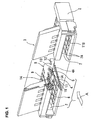
- Fig. 1 and Fig. 2 are partial sectional perspective views of a connector according to a first embodiment of the present invention.
- Fig. 1 shows a state that a pressing portion member is located at an open position
- Fig. 2 shows a state that the pressing portion member is located at a closed position.
- a flat cable to be inserted in an A direction is omitted in both of the figures.
- reference numeral 1 denotes a housing made of an electrically insulating material and having a shape with a wide width in the left-to-right direction (a direction perpendicular to the A direction viewed from above). Except sidewall portions 2 on left and right sides, a front upper portion is opened in the A direction.
- the pressing portion member 3 When the pressing portion member 3 is located at the closed position, the pressing portion member 3 is retained in the open space.
- the connector As a whole has a cuboid shape as shown in Fig. 2.
- the housing 1 includes a bottom wall portion 4, a middle wall portion 5, and an upper wall portion 6, all of which are connected with the sidewall portions 2.
- the bottom wall portion 4 forms a bottom surface for placing a circuit board (not shown), and extends over a whole rectangular shape of the housing 1.
- the middle wall portion 5 has a short length in the A direction, i.e., an insertion direction of the cable, and is situated at a middle in a height direction.
- the middle wall portion 5 is formed to protrude from the bottom wall portion 4, and is provided with slit grooves 5A for receiving lower arm portions (described later).
- the upper wall portion 6 is provided at a front edge in the A direction.
- the upper wall portion 6, the bottom wall portion 4, and the sidewall portions 2 constitute an insertion opening 7 for a flat cable.
- the insertion opening 7 has a tapered portion 7A for easily inserting the cable.
- the housing 1 protrudes beyond free ends of upper arm portions and middle arm portions, and is provided with an abutting portion 1A for regulating the pressing portion member 3 from deviating backward.
- the housing 1 has a cut portion corresponding to the upper arm portions and the middle arm portions at an arranging position of terminals 8.
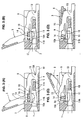
- the terminals 8 held with the housing 1 maintain a flat surface of a metal plate as is, and are formed with a forming process such as a punching process.
- the terminals 8 include the upper arm portions 9; the middle arm portions 10; the lower arm portions 11; and connecting portions 12.
- the lower arm portions 11 extend from a rear side (right side in Fig. 3(A)) to a front side, and are inserted into the slits 5A formed in the middle wall portion 5 of the housing 1 in the direction. Projections 11A formed on the lower arm portions 11 as held portions bite into the slits 5A and are held with the slits 5A, thereby preventing pulling out.
- Supporting portions 11B with a projecting shape are formed at positions near inner edge free ends of the lower arm portions 11.
- the connecting portions 12 are disposed at rear sides of the lower arm portions 11, and extend toward outside of the housing 1. Lower edges of the connecting portions 12 are situated slightly below a lower surface of the housing 1, and are slightly inclined downwardly toward the rear side.
- the upper arm portions 9 and the middle arm portions 10 extend toward the left side from positions at left sides of the flexible portions 13 curved and extending upwardly from base portions of the lower arm portions 11.
- the flexible portions 13 have narrow portions formed of recessed curved portions 13A at positions near the base portions of the connecting portion 12 for increasing flexibility.
- the upper arm portions 9 and the middle arm portions 10 have a shape branched at a position on a left side of the flexible portions 13, and have free ends at positions substantially same as those of the free ends of the lower arm portions 11.
- the upper arm portions 9 have step portions 9A in lower edges at the middle thereof, and are tapered toward the free ends thereof.
- a cam shaft portion 14 of the pressure potion 3 is retained between the upper arm portions 9 and the middle arm portions 10 at a range in front of the step portions 9A.
- the middle arm portions 10 have an overall shape narrower than that of the upper arm portions 9, and have contacting portions 10A with a projecting shape at lower edge distal ends thereof.
- a portion from the contacting portion 10A to a position contacting with the cam shaft portion 14 of the pressing portion member 3 has a width larger than that of a portion to a base portion, thereby increasing rigidity.
- the upper arm portions 9 and the middle arm portions 10 deform together around the flexible portions 13, and also have elasticity individually so as to deform in a direction separating from each other upon receiving an external force from the cam shaft portion 14 of the pressing portion member. At this time, since the middle arm portions 10 are narrower than the upper arm portions 9, so that the deformation thereof becomes greater by the amount.
- the pressing portion member 3 has a lid shape relative to the housing 1 as shown in Fig. 2, and has a lever shape in a sectional view shown in Fig. 3.
- the pressing portion member 3 is formed of an insulating material similar to the housing 1, and has the cam shaft portion 14 as shown in Fig. 3.
- the pressing portion member 3 rotates around the cam shaft portion 14, and is capable of moving between the open position shown in Fig. 3(A) and the closed position shown in Fig. 3(D).
- the pressing portion member 3 is provided with groove portions 15 at positions corresponding to the terminals 8 in an area where the cam shaft portion 14 is located, that is, a lower half portion shown in Fig. 3(A), so that the distal ends of the upper arm portions 9 and the middle arm portions 10 of the terminals 8 can penetrate.
- the cam shaft portion 14 has a sectional shape such that the section is elongated laterally, that is, in a longitudinal direction of the upper arm portions 9 and the middle arm portions 10, when the pressing portion member 3 is located at the open position shown in Fig.
- the cam shaft portion 14 has a short diameter smaller than a distance between the upper arm portion 9 and the middle arm portion 10 when they become a free state, and a long diameter larger than the distance.
- a downward restoration force is generated as a reaction force of the deformation around the flexible portions 13 accompanying with the upward shift of the upper arm portions 9.
- the force allows the middle arm portions 10 to shift together, thereby increasing a force pressing the flat cable C.
- the pressing portion member 3 has the groove portions 15 around the cam shaft portion 14 and opens. Accordingly, as shown in Fig. 3(D), when the pressing portion member 3 is located at the closed position, the upper edges of the upper arm portions 9 are retained in the groove portions 15, thereby allowing the upper arm portions 9 to shift upwardly and preventing the connector from increasing a size thereof in the height direction.
- the region near the free end of the middle arm portion, i.e., the region supporting the cam shaft from the contacting portion has a width in the height direction larger than the middle portion connected to the base portion of the middle arm portion, thereby providing high rigidity.
- the case that the flat cable has the contacting portion on the upper surface is explained as an example.
- the connecting portion is provided on a lower surface or both upper and lower surfaces, the cable is applicable to the present embodiment.
- the supporting portions 11B with a projecting shape of the lower arm portions 11 function as the contact portions of the terminals. This is true for other embodiments.
- the abutting portion 1A of the housing 1 regulates the pressing portion member 3, so that the rotational center is not shifted backwardly when the pressing portion member 3 rotates.
- the cam shaft portion 14 as the rotational center is regulated in the terminals as well.
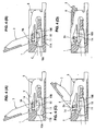
- the upper arm portions 9 of the terminals 3 are provided with recess portions 9A for guiding a rotation
- the middle arm portions 10 are provided with projections 10B, so that the recess portions 9A and the projections 10A function as a regulating portion. Accordingly, as shown in Figs. 4(A) to (D), when the pressing portion member 3 moves from the open position to the closed position, the cam shaft portion 14 of the pressing portion member 3 is directly regulated from shifting backwardly with the recess portions 9A and the projections 10A.
- the lower edges of the lower arm portions 11 form gaps relative to the bottom wall portion 4 of the housing 1 in the front region thereof, thereby providing flexibility. Accordingly, the lower arm portions 11 are pushed by the flat cable C to be able to shift downwardly when the pressing portion member 3 moves to the closed position. Therefore, even though the positions of the contacting portions 10A or the supporting portions 11B of the plural terminals are varied, it is possible to absorb the variances.
- the upper arm portions 9 and the middle arm portions 10 of the terminals 3 are branched via the region extending upwardly from the base portions of the lower arm portions 11. In the present embodiment shown in Fig. 5, not via the region, they are branched immediately from the base portions of the lower arm portions. In this case, when the cam shaft portion 14 rotates, the upper arm portions 9 and the middle arm portions 10 deform in the direction separating from each other, and the upper arm portions 9 try to return downwardly around the flexible portions 13, thereby obtaining the restoration force.
- first terminals 16 and second terminals 17 are provided, and both terminals 16 and 17 are arranged alternately.
- the first terminal 16 does not have the middle arm portion
- the second terminal 17 does not have the upper arm portion.
- the first terminals 16 have the upper arm portions 9 and the lower arm portions
- the second terminals 17 have the middle arm portions 10 and the lower arm portions 11. Accordingly, the cam shaft portion 14 of the pressing portion member 3 is rotationally supported and guided with the pair of the upper arm portions 9 of the first terminals 16 and the middle arm portions 10 of the second terminals 17.
Landscapes
- Coupling Device And Connection With Printed Circuit (AREA)
Applications Claiming Priority (1)
| Application Number | Priority Date | Filing Date | Title |
|---|---|---|---|
| JP2004226839A JP4282014B2 (ja) | 2004-08-03 | 2004-08-03 | 平型ケーブル用電気コネクタ |
Publications (2)
| Publication Number | Publication Date |
|---|---|
| EP1624532A2 true EP1624532A2 (de) | 2006-02-08 |
| EP1624532A3 EP1624532A3 (de) | 2007-10-03 |
Family
ID=35115747
Family Applications (1)
| Application Number | Title | Priority Date | Filing Date |
|---|---|---|---|
| EP05016672A Withdrawn EP1624532A3 (de) | 2004-08-03 | 2005-08-01 | Elektrischer Verbinder für Flachkabel |
Country Status (6)
| Country | Link |
|---|---|
| US (1) | US6997729B2 (de) |
| EP (1) | EP1624532A3 (de) |
| JP (1) | JP4282014B2 (de) |
| KR (1) | KR20060046536A (de) |
| CN (1) | CN100394647C (de) |
| TW (1) | TWI275218B (de) |
Families Citing this family (25)
| Publication number | Priority date | Publication date | Assignee | Title |
|---|---|---|---|---|
| JP4054741B2 (ja) * | 2003-09-26 | 2008-03-05 | 日本圧着端子製造株式会社 | 低背型fpc用zifコネクタ |
| JP4054740B2 (ja) * | 2003-09-26 | 2008-03-05 | 日本圧着端子製造株式会社 | Fpc用zifコネクタ |
| CN1879260A (zh) * | 2003-10-16 | 2006-12-13 | 莫列斯公司 | 扁平电路连接器 |
| JP4168986B2 (ja) * | 2004-07-06 | 2008-10-22 | モレックス インコーポレーテッド | Fpc用コネクタ |
| JP4484218B2 (ja) * | 2004-10-22 | 2010-06-16 | 第一電子工業株式会社 | コネクタ |
| TWI283089B (en) * | 2005-02-05 | 2007-06-21 | Chief Land Electronic Co Ltd | Terminal buckling structure and buckling method thereof |
| JP4283777B2 (ja) * | 2005-03-09 | 2009-06-24 | 京セラエルコ株式会社 | コネクタ |
| CN2821903Y (zh) * | 2005-07-20 | 2006-09-27 | 富士康(昆山)电脑接插件有限公司 | 电连接器 |
| JP4783081B2 (ja) * | 2005-07-21 | 2011-09-28 | 株式会社アイペックス | 電気コネクタ |
| JP4938303B2 (ja) * | 2005-12-16 | 2012-05-23 | 日本圧着端子製造株式会社 | コネクタ |
| JP4515403B2 (ja) * | 2006-03-17 | 2010-07-28 | ホシデン株式会社 | フレキシブル基板用コネクタ |
| JP4707610B2 (ja) * | 2006-05-31 | 2011-06-22 | モレックス インコーポレイテド | ケーブル用コネクタ |
| JP5108615B2 (ja) * | 2008-05-09 | 2012-12-26 | モレックス インコーポレイテド | コネクタ |
| KR100946176B1 (ko) * | 2009-04-29 | 2010-03-08 | (주)우주일렉트로닉스 | 커넥터 |
| JP5016635B2 (ja) * | 2009-06-02 | 2012-09-05 | 日本航空電子工業株式会社 | コネクタ |
| JP5391104B2 (ja) * | 2010-02-12 | 2014-01-15 | モレックス インコーポレイテド | コネクタ |
| US8535089B2 (en) | 2011-07-25 | 2013-09-17 | Tyco Electronics Corporation | Connector assembly |
| US8430685B2 (en) * | 2011-07-25 | 2013-04-30 | Tyco Electronics Corporation | Connector assembly |
| TWI496366B (zh) * | 2011-08-04 | 2015-08-11 | Dai Ichi Seiko Co Ltd | 電連接器 |
| JP5862387B2 (ja) * | 2012-03-15 | 2016-02-16 | オムロン株式会社 | コネクタ |
| TWI509906B (zh) * | 2012-12-10 | 2015-11-21 | Ya Ping Lin | 電連接器 |
| CN106410482A (zh) * | 2016-06-02 | 2017-02-15 | 浙江新富尔电子有限公司 | 一种立式掀盖连接器 |
| JP6723875B2 (ja) * | 2016-08-26 | 2020-07-15 | ヒロセ電機株式会社 | 平型導体用電気コネクタ |
| JP1585292S (de) * | 2017-02-02 | 2017-09-04 | ||
| JP1585293S (de) * | 2017-02-02 | 2017-09-04 |
Citations (4)
| Publication number | Priority date | Publication date | Assignee | Title |
|---|---|---|---|---|
| JP2002093504A (ja) * | 2000-09-18 | 2002-03-29 | Japan Aviation Electronics Industry Ltd | Fpc用コネクタ |
| US6431897B1 (en) * | 1999-10-06 | 2002-08-13 | Japan Aviation Electroncis Industry Limited | Connector having a rotary actuator engaged with a contact in a direction parallel to a sheet-like object connected to the connector |
| EP1337006A2 (de) * | 2002-02-19 | 2003-08-20 | Molex Incorporated | Verbinder für flache Schaltungseinheit |
| WO2003107487A1 (en) * | 2002-06-12 | 2003-12-24 | Molex Incorporated | Flat circuit connector with improved actuator |
Family Cites Families (9)
| Publication number | Priority date | Publication date | Assignee | Title |
|---|---|---|---|---|
| US2811700A (en) * | 1956-05-14 | 1957-10-29 | Bell Telephone Labor Inc | Electrical connector for printed wiring board |
| US3475717A (en) * | 1967-03-31 | 1969-10-28 | Itt | Zero force connector |
| JP3075707B2 (ja) * | 1997-12-24 | 2000-08-14 | 日本圧着端子製造株式会社 | プリント配線板用コネクタ |
| JP4607348B2 (ja) * | 2001-02-07 | 2011-01-05 | 第一電子工業株式会社 | コネクタ |
| JP2002252049A (ja) * | 2001-02-22 | 2002-09-06 | Jst Mfg Co Ltd | 電気コネクタ |
| JP3741619B2 (ja) * | 2001-03-23 | 2006-02-01 | ヒロセ電機株式会社 | フラットケーブル用電気コネクタ |
| JP3605586B2 (ja) * | 2001-09-25 | 2004-12-22 | 日本圧着端子製造株式会社 | フレキシブル基板用コネクタ |
| JP2003217718A (ja) * | 2002-01-18 | 2003-07-31 | Smk Corp | プリント配線基板用コネクタ |
| TWM250340U (en) * | 2003-08-01 | 2004-11-11 | Hon Hai Prec Ind Co Ltd | Electrical connector |
-
2004
- 2004-08-03 JP JP2004226839A patent/JP4282014B2/ja not_active Expired - Fee Related
-
2005
- 2005-07-07 TW TW094123011A patent/TWI275218B/zh not_active IP Right Cessation
- 2005-07-21 KR KR1020050066291A patent/KR20060046536A/ko not_active Application Discontinuation
- 2005-07-21 US US11/185,833 patent/US6997729B2/en not_active Expired - Fee Related
- 2005-08-01 EP EP05016672A patent/EP1624532A3/de not_active Withdrawn
- 2005-08-02 CN CNB200510088581XA patent/CN100394647C/zh not_active Expired - Fee Related
Patent Citations (4)
| Publication number | Priority date | Publication date | Assignee | Title |
|---|---|---|---|---|
| US6431897B1 (en) * | 1999-10-06 | 2002-08-13 | Japan Aviation Electroncis Industry Limited | Connector having a rotary actuator engaged with a contact in a direction parallel to a sheet-like object connected to the connector |
| JP2002093504A (ja) * | 2000-09-18 | 2002-03-29 | Japan Aviation Electronics Industry Ltd | Fpc用コネクタ |
| EP1337006A2 (de) * | 2002-02-19 | 2003-08-20 | Molex Incorporated | Verbinder für flache Schaltungseinheit |
| WO2003107487A1 (en) * | 2002-06-12 | 2003-12-24 | Molex Incorporated | Flat circuit connector with improved actuator |
Also Published As
| Publication number | Publication date |
|---|---|
| US20050255732A1 (en) | 2005-11-17 |
| CN1734847A (zh) | 2006-02-15 |
| JP2006049031A (ja) | 2006-02-16 |
| KR20060046536A (ko) | 2006-05-17 |
| US6997729B2 (en) | 2006-02-14 |
| TW200607186A (en) | 2006-02-16 |
| CN100394647C (zh) | 2008-06-11 |
| TWI275218B (en) | 2007-03-01 |
| EP1624532A3 (de) | 2007-10-03 |
| JP4282014B2 (ja) | 2009-06-17 |
Similar Documents
| Publication | Publication Date | Title |
|---|---|---|
| US6997729B2 (en) | Electrical connector for flat cable | |
| US6893288B2 (en) | Electrical connector for a flat cable | |
| US7713078B2 (en) | Electrical connector | |
| US9601854B2 (en) | Female terminal | |
| US8105105B2 (en) | Electrical connector | |
| EP2180553A2 (de) | Elektrischer Anschluss und Endgerät für elektrischen Anschluss | |
| KR20110139092A (ko) | 커넥터 | |
| US7553203B2 (en) | Connecting terminal | |
| JP2015510242A (ja) | 電気コネクタのストレインリリーフ | |
| US9276334B1 (en) | Poke-in electrical connector | |
| US6602083B2 (en) | Electrical connector for flat cable and its manufacturing method | |
| JP3965380B2 (ja) | オス端子及びこれを用いたオスコネクタ | |
| EP1385232A2 (de) | Elektrische Verbinderanordnung, Stecker und Buchse | |
| JP3131155B2 (ja) | 電気コネクタ | |
| US7201606B2 (en) | Wire connection structure and connector | |
| JP2020042903A (ja) | 平型導体用電気コネクタおよび平型導体用電気コネクタ組立体 | |
| US11381009B2 (en) | Contact and connector | |
| JP3982977B2 (ja) | フレキシブル基板用電気コネクタ | |
| EP0884802B1 (de) | Terminal und Gehäuse mit Terminal | |
| CN212062743U (zh) | 连接器端子 | |
| EP1037315B1 (de) | Verbinderkontakt | |
| JP5665533B2 (ja) | コネクタ組立体 | |
| JP2018156774A (ja) | フレキシブルケーブル用コネクタ | |
| JP2004119396A (ja) | フラットケーブル用コネクタ、フラットケーブル用コネクタに用いられる端子金具及びフラットケーブル用コネクタに用いられる端子金具の製造方法 | |
| KR20050065451A (ko) | 접속단자 |
Legal Events
| Date | Code | Title | Description |
|---|---|---|---|
| PUAI | Public reference made under article 153(3) epc to a published international application that has entered the european phase |
Free format text: ORIGINAL CODE: 0009012 |
|
| AK | Designated contracting states |
Kind code of ref document: A2 Designated state(s): AT BE BG CH CY CZ DE DK EE ES FI FR GB GR HU IE IS IT LI LT LU LV MC NL PL PT RO SE SI SK TR |
|
| AX | Request for extension of the european patent |
Extension state: AL BA HR MK YU |
|
| PUAL | Search report despatched |
Free format text: ORIGINAL CODE: 0009013 |
|
| AK | Designated contracting states |
Kind code of ref document: A3 Designated state(s): AT BE BG CH CY CZ DE DK EE ES FI FR GB GR HU IE IS IT LI LT LU LV MC NL PL PT RO SE SI SK TR |
|
| AX | Request for extension of the european patent |
Extension state: AL BA HR MK YU |
|
| 17P | Request for examination filed |
Effective date: 20080401 |
|
| AKX | Designation fees paid |
Designated state(s): DE FR GB IT |
|
| 17Q | First examination report despatched |
Effective date: 20080625 |
|
| STAA | Information on the status of an ep patent application or granted ep patent |
Free format text: STATUS: THE APPLICATION IS DEEMED TO BE WITHDRAWN |
|
| 18D | Application deemed to be withdrawn |
Effective date: 20081105 |