EP1621708A2 - Verriegelungsvorrichtung an Lukendeckeln oder Verschlussklappen von Fahrzeugen, insbesondere Kampffahrzeugen - Google Patents
Verriegelungsvorrichtung an Lukendeckeln oder Verschlussklappen von Fahrzeugen, insbesondere Kampffahrzeugen Download PDFInfo
- Publication number
- EP1621708A2 EP1621708A2 EP05013651A EP05013651A EP1621708A2 EP 1621708 A2 EP1621708 A2 EP 1621708A2 EP 05013651 A EP05013651 A EP 05013651A EP 05013651 A EP05013651 A EP 05013651A EP 1621708 A2 EP1621708 A2 EP 1621708A2
- Authority
- EP
- European Patent Office
- Prior art keywords
- locking
- elements
- locking device
- hatch
- flap
- Prior art date
- Legal status (The legal status is an assumption and is not a legal conclusion. Google has not performed a legal analysis and makes no representation as to the accuracy of the status listed.)
- Granted
Links
- 230000005540 biological transmission Effects 0.000 claims abstract description 16
- 238000006073 displacement reaction Methods 0.000 claims abstract description 5
- 230000000694 effects Effects 0.000 claims description 2
- 238000007789 sealing Methods 0.000 description 4
- 230000006835 compression Effects 0.000 description 1
- 238000007906 compression Methods 0.000 description 1
- 230000008878 coupling Effects 0.000 description 1
- 238000010168 coupling process Methods 0.000 description 1
- 238000005859 coupling reaction Methods 0.000 description 1
- 230000001419 dependent effect Effects 0.000 description 1
- 238000011161 development Methods 0.000 description 1
- 230000018109 developmental process Effects 0.000 description 1
Images

Classifications
-
- E—FIXED CONSTRUCTIONS
- E05—LOCKS; KEYS; WINDOW OR DOOR FITTINGS; SAFES
- E05C—BOLTS OR FASTENING DEVICES FOR WINGS, SPECIALLY FOR DOORS OR WINDOWS
- E05C9/00—Arrangements of simultaneously actuated bolts or other securing devices at well-separated positions on the same wing
- E05C9/06—Arrangements of simultaneously actuated bolts or other securing devices at well-separated positions on the same wing with three or more sliding bars
- E05C9/063—Arrangements of simultaneously actuated bolts or other securing devices at well-separated positions on the same wing with three or more sliding bars extending along three or more sides of the wing or frame
-
- E—FIXED CONSTRUCTIONS
- E05—LOCKS; KEYS; WINDOW OR DOOR FITTINGS; SAFES
- E05B—LOCKS; ACCESSORIES THEREFOR; HANDCUFFS
- E05B79/00—Mounting or connecting vehicle locks or parts thereof
- E05B79/10—Connections between movable lock parts
- E05B79/20—Connections between movable lock parts using flexible connections, e.g. Bowden cables
-
- E—FIXED CONSTRUCTIONS
- E05—LOCKS; KEYS; WINDOW OR DOOR FITTINGS; SAFES
- E05B—LOCKS; ACCESSORIES THEREFOR; HANDCUFFS
- E05B83/00—Vehicle locks specially adapted for particular types of wing or vehicle
- E05B83/01—Locks for military or armoured vehicles
-
- E—FIXED CONSTRUCTIONS
- E05—LOCKS; KEYS; WINDOW OR DOOR FITTINGS; SAFES
- E05C—BOLTS OR FASTENING DEVICES FOR WINGS, SPECIALLY FOR DOORS OR WINDOWS
- E05C9/00—Arrangements of simultaneously actuated bolts or other securing devices at well-separated positions on the same wing
- E05C9/24—Means for transmitting movements between vertical and horizontal sliding bars, rods or cables for the fastening of wings, e.g. corner guides
-
- F—MECHANICAL ENGINEERING; LIGHTING; HEATING; WEAPONS; BLASTING
- F41—WEAPONS
- F41H—ARMOUR; ARMOURED TURRETS; ARMOURED OR ARMED VEHICLES; MEANS OF ATTACK OR DEFENCE, e.g. CAMOUFLAGE, IN GENERAL
- F41H5/00—Armour; Armour plates
- F41H5/22—Manhole covers, e.g. on tanks; Doors on armoured vehicles or structures
- F41H5/223—Manhole covers specially adapted for armoured or fighting vehicles
-
- E—FIXED CONSTRUCTIONS
- E05—LOCKS; KEYS; WINDOW OR DOOR FITTINGS; SAFES
- E05B—LOCKS; ACCESSORIES THEREFOR; HANDCUFFS
- E05B17/00—Accessories in connection with locks
- E05B17/0025—Devices for forcing the wing firmly against its seat or to initiate the opening of the wing
-
- E—FIXED CONSTRUCTIONS
- E05—LOCKS; KEYS; WINDOW OR DOOR FITTINGS; SAFES
- E05B—LOCKS; ACCESSORIES THEREFOR; HANDCUFFS
- E05B17/00—Accessories in connection with locks
- E05B17/0025—Devices for forcing the wing firmly against its seat or to initiate the opening of the wing
- E05B17/0029—Devices for forcing the wing firmly against its seat or to initiate the opening of the wing motor-operated
Definitions
- the invention relates to a locking device on hatch covers or flaps of vehicles, in particular combat vehicles, with the features of the preamble of claim 1.
- Such locking devices are known per se. They have the disadvantage that when a good sealing closure of the hatch cover or the flap is to be achieved, distributed around the circumference arranged locking elements must all be operated individually, which is tedious and time consuming.
- the invention has for its object to design a locking device with the features of the preamble of claim 1 so that the locking and unlocking for all locking elements of a hatch cover or a flap can be effected together by a handle or a button and still a safe and secure good sealing closure can be achieved.
- the solution of this object is achieved according to the invention with the features of the characterizing part of claim 1.
- a basic idea of the invention is to couple the locking elements respectively arranged on a hatch cover or a closure flap by means of a transmission element circulating on the circumference of the hatch cover or the closure flap to an actuating device arranged on the outside and / or the inside of the hatch cover or the closure flap can be locked or unlocked simultaneously by means of the actuator all locking elements of a hatch cover or a flap.
- the circulating transmission element from arranged in a guide slide rods and Eckumlenkettin, for example in the form of chain links, composed.
- the actuating device can be designed as an actuating lever for manual operation or as an electric geared motor for a motorized operation, which can also be centrally controlled.
- the locking device serve as locking elements arranged on the sliding rods locking rollers and arranged as counter-elements in the edge region of the hatch opening and the loading opening hook-shaped lock plates which are designed and arranged such that the locking rollers engage in a displacement of the transmission element in the lock plates ,
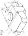
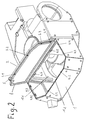
- FIG. 1 and 2 show the vehicle housing 1 of a combat vehicle, not shown in the rest with a arranged in the rear cargo area 1.1, the charging opening 1.2 is closed by means of a flap 2.
- the closure flap 2 is pivotable about a horizontal pivot axis 2.1.
- the locking device In the closed state of the closure flap 2 shown in FIG. 1, this can be locked to the vehicle housing 1.
- the locking device explained in more detail below can be actuated by means of a pivotable actuating lever 5 arranged on the outside of the closure flap 2 for locking and unlocking.
- the locking device has a at the periphery of the flap. 2 circumferentially arranged in a guide 8 transmission element, which is composed of sliding rods 6.1 to 6.6 and arranged in the corner regions of the flap 2 Eckumlenkettin 7.1 to 7.6.
- This transmission element is displaceable in its longitudinal direction in the guide 8.
- the corner deflection elements 7.1 to 7.6 are each composed of chain links guided in sliding guides 8.1 to 8.6.
- This design of the transmission element ensures that it can be adapted to any polygonal contours of a flap or a hatch cover.
- both the locking elements 3.1 to 3.8 and the counter-elements 4.1 to 4.8 are arranged distributed at different distances on the circumference of the hatch cover 2 and the loading opening 1.2.
- the locking elements 3.1 to 3.8 are formed as locking rollers which are rotatably mounted directly on the slide rods 6.1 to 6.6.
- the counter-elements 4.1 to 4.8 are designed as hook-shaped lock plates and arranged so that the hook opening in each case runs parallel to the direction of movement of the respective slide bar, such that upon displacement of the slide bar, the associated locking roller in the hook opening of the lock plate or led out of her becomes.
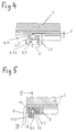
- This is for example for the locking roller 3.1 and the lock plate 4.1 Figs. 4 and 5 refer. In Fig. 4 is shown by solid lines, the locking position, in which the locking roller engages 3.1 in the hook-shaped opening of the lock plate 4.1.
- the locking roller In the unlocked state, the locking roller is designated by reference numeral 3.1 'and shown in dashed lines. It lies in front of the hook opening of the lock plate 4.1. The locking stroke is marked V.
- the lock plate 4.1 is fastened via screw 4.12 adjustable on the vehicle body 1.
- the lock plate 4.1 has, on the inside of the hook-shaped part, an oblique surface 4.11, onto which the locking roller 3.1 assigned to it runs during the locking movement.
- the closure flap 2 is pulled sealingly against the force effect of a seal 11 shown in FIG. 5 in the closed position during locking.
- the sealing stroke is indicated in Fig. 4 with d.
- FIG. 1 The coupling of the transmission element to the pivotable actuating lever 5 is shown in FIG.
- a gear 5.1 rotating on actuation about the pivot axis 5.2 is arranged on the actuating lever 5, which engages in a toothed rod 9 fastened to the slide bar 6.6.
- the slide bar moves 6.6 and with her the entire transmission element in its longitudinal direction by a predetermined distance and the pivoting back of the operating lever 5 in the locking position back to the starting position. In this way, a manual locking and unlocking of the closure flap arranged on the locking elements 3.1 to 3.8 is possible.
- a gear motor which is indicated in Fig. 3 by reference numeral 5 '.
- the output gear of such a gear motor then engages the rack 9 on the slide bar 6.6 and causes the displacement of the transmission element.
- Such a geared motor can also be controlled centrally out of the vehicle.
- the illustrated and described locking device is used in the embodiment for locking a pivotable about a horizentale pivot axis flap.
- this locking device is also at a suitable for a horizontal axis swiveling hatch cover.
- the locking device can be used on flaps or hatch covers which are pivotable about a vertical pivot axis or displaceable in the horizontal direction and then lowered onto the loading opening or hatch opening.
Landscapes
- Engineering & Computer Science (AREA)
- Mechanical Engineering (AREA)
- General Engineering & Computer Science (AREA)
- Lock And Its Accessories (AREA)
- Outer Garments And Coats (AREA)
- Treatments For Attaching Organic Compounds To Fibrous Goods (AREA)
- Power-Operated Mechanisms For Wings (AREA)
- Aiming, Guidance, Guns With A Light Source, Armor, Camouflage, And Targets (AREA)
Abstract
Description
- Die Erfindung betrifft eine Verriegelungsvorrichtung an Lukendeckeln oder Verschlussklappen von Fahrzeugen, insbesondere Kampffahrzeugen, mit den Merkmalen aus dem Oberbegriff des Patentanspruchs 1.
- Derartige Verriegelungsvorrichtungen sind an sich bekannt. Sie haben den Nachteil, dass, wenn ein gut dichtender Verschluss des Lukendeckels oder der Verschlussklappe erreicht werden soll, die am Umfang verteilt angeordneten Verriegelungselemente alle einzeln betätigt werden müssen, was mühsam und zeitaufwendig ist.
- Der Erfindung liegt die Aufgabe zugrunde, eine Verriegelungsvorrichtung mit den Merkmalen aus dem Oberbegriff des Patentanspruchs 1 so auszugestalten, dass die Verriegelung und die Entriegelung für alle Verriegelungselemente eines Lukendeckels oder einer Verschlussklappe gemeinsam durch einen Handgriff oder einen Knopfdruck bewirkt werden kann und trotzdem ein sicherer und gut dichtender Verschluss erreicht werden kann. Die Lösung dieser Aufgabe erfolgt erfindungsgemäss mit den Merkmalen aus dem kennzeichnenden Teil des Patentanspruch 1. Vorteilhafte Weiterbildungen der Erfindung sind in den abhängigen Ansprüchen beschrieben.
- Ein Grundgedanke der Erfindung besteht darin, die jeweils an einem Lukendeckel oder einer Verschlussklappe angeordneten Verriegelungselemente mittels eines am Umfang des Lukendeckels oder der Verschlussklappe umlaufenden Übertragungselements derart an eine an der Außenseite und/oder der Innenseite des Lukendeckels bzw. der Verschlussklappe angeordnete Betätigungsvorrichtung anzukoppeln, dass mittels der Betätigungsvorrichtung alle Verriegelungselemente eines Lukendeckels bzw. einer Verschlussklappe gleichzeitig verriegelt oder entriegelt werden können. Dabei ist das umlaufende Übertragungselement aus in einer Führung angeordneten Gleitstangen und Eckumlenkelementen, beispielsweise in der Form von Kettengliedern, zusammengesetzt. Dies bringt, wie weiter unten anhand eines Ausführungsbeispiels erläutert, den Vorteil mit sich, dass das Übertragungselement an praktisch jede Kontur eines Lukendeckels oder einer Verschlussklappe angepasst werden kann. Die Betätigungsvorrichtung kann als Betätigungshebel für manuelle Bedienung oder als elektrischer Getriebemotor für eine motorische Betätigung, die auch zentral gesteuert sein kann, ausgebildet sein.
- Bei einer besonders vorteilhaften Ausführungsform der erfindungsgemäßen Verriegelungsvorrichtung dienen als Verriegelungselemente an den Gleitstangen angeordnete Verriegelungsrollen und als Gegenelemente im Randbereich der Lukenöffnung bzw. der Ladeöffnung angeordnete hakenförmige Schlossplatten, die derart ausgebildet und angeordnet sind, dass die Verriegelungsrollen bei einer Verschiebung des Übertragungselements in die Schlossplatten eingreifen. Dies ist eine konstruktiv besonders einfache Ausführungsform, die zudem den Vorteil hat, dass der hakenförmig ausgebildete Teil der Schlossplatte eine Schrägfläche aufweisen kann, auf welche die Verriegelungsrolle bei der Verriegelungsbewegung aufläuft, und auf diese Weise kann ein Dichtungshub ausgeführt werden, der den Lukendeckel bzw. die Verschlussklappe gegen die Kraft einer am Deckel oder Gehäuse angeordneten Dichtung unter Zusammenpressung der Dichtung in die Verschlussstellung führt und somit den Lukendeckel oder die Verschlussklappe gegenüber dem Fahrzeuggehäuse sicher abdichtet.
- Im folgenden wird anhand der beigefügten Zeichnungen ein Ausführungsbeispiel für eine Verriegelungsvorrichtung nach der Erfindung näher erläutert.
-
- Fig. 1
- das Fahrzeuggehäuse eines Kampffahrzeugs mit geschlossener Verschlussklappe an einer Ladeöffnung;
- Fig. 2
- das Fahrzeuggehäuse nach Fig. 1 bei geöffneter Verschlussklappe;
- Fig. 3
- in gegenüber Fig. 1 und 2 vergrößerter Darstellung eine Aufsicht auf die Ladeöffnung im geschlossenen Zustand der Verschlussklappe mit den an der Verschlussklappe angeordneten Teilen der Verriegelungsvorrichtung;
- Fig. 4
- einen Schnitt nach der Linie IV-IV in Fig. 5;
- Fig. 5
- in gegenüber Fig. 3 vergrößerter Darstellung einen Schnitt nach der Linie V-V in Fig. 3.
- Die Fig. 1 und 2 zeigen das Fahrzeuggehäuse 1 eines im übrigen nicht dargestellten Kampffahrzeugs mit einem im Heckbereich angeordneten Laderaum 1.1, dessen Ladeöffnung 1.2 mittels einer Verschlussklappe 2 verschließbar ist. Die Verschlussklappe 2 ist um eine horizontale Schwenkachse 2.1 schwenkbar.
- In dem in Fig. 1 dargestellten geschlossenen Zustand der Verschlussklappe 2 ist die diese mit dem Fahrzeuggehäuse 1 verriegelbar. Die im folgenden näher erläuterte Verriegelungsvorrichtung ist mittels eines an der Außenseite der Verschlussklappe 2 angeordneten schwenkbaren Betätigungshebels 5 zur Verriegelung und Entriegelung betätigbar. Die Verriegelungsvorrichtung besitzt ein am Umfang der Verschlussklappe 2 umlaufend in einer Führung 8 angeordnetes Übertragungselement, welches aus Gleitstangen 6.1 bis 6.6 und in den Eckbereichen der Verschlussklappe 2 angeordneten Eckumlenkelementen 7.1 bis 7.6 zusammengesetzt ist. Dieses Übertragungselement ist in seiner Längsrichtung in der Führung 8 verschiebbar. Wie Fig. 3 zu entnehmen, sind die Eckumlenkelemente 7.1 bis 7.6 jeweils aus in Gleitführungen 8.1 bis 8.6 geführten Kettengliedern zusammengesetzt. Durch diese Ausbildung des Übertragungselements ist sichergestellt, dass dieses an beliebige vieleckige Konturen einer Verschlussklappe oder eines Lukendeckels angepasst werden kann. An den Gleitstangen 6.1 bis 6.6 sind Verriegelungselemente 3.1 bis 3.8 angeordnet, welche mit Gegenelementen 4.1 bis 4.8 zusammenwirken, die am Fahrzeuggehäuse 1 im Randbereich der Lukenöffnung 1.2 angeordnet sind. Wie den Fig. 2 und 3 zu entnehmen, sind sowohl die Verriegelungselemente 3.1 bis 3.8 als auch die Gegenelemente 4.1 bis 4.8 mit unterschiedlichen Abständen am Umfang des Lukendeckels 2 bzw. der Ladeöffnung 1.2 verteilt angeordnet.
- Die Verriegelungselemente 3.1 bis 3.8 sind als Verriegelungsrollen ausgebildet, die unmittelbar an den Gleitstangen 6.1 bis 6.6 drehbar befestigt sind. Die Gegenelemente 4.1 bis 4.8 sind als hakenförmig ausgestaltete Schlossplatten ausgebildet und so angeordnet, dass die Hakenöffnung jeweils parallel zur Bewegungsrichtung der jeweiligen Gleitstange verläuft, derart, dass bei einer Verschiebung der Gleitstange die ihr zugeordnete Verriegelungsrolle in die Hakenöffnung der Schlossplatte hinein- oder aus ihr herausgeführt wird. Dies ist beispielsweise für die Verriegelungsrolle 3.1 und die Schlossplatte 4.1 den Fig. 4 und 5 zu entnehmen. In Fig. 4 ist mit durchgezogenen Linien die Verriegelungsstellung dargestellt, in welcher die Verriegelungsrolle 3.1 in die hakenförmige Öffnung der Schlossplatte 4.1 eingreift. Im entriegelten Zustand ist die Verriegelungsrolle mit Bezugsziffer 3.1' bezeichnet und gestrichelt dargestellt. Sie liegt vor der Hakenöffnung der Schlossplatte 4.1. Der Verriegelungshub ist mit V gekennzeichnet. Die Schlossplatte 4.1 ist über Schraubverbindungen 4.12 justierbar am Fahrzeuggehäuse 1 befestigt.
- Wie Fig. 4 zu entnehmen, besitzt die Schlossplatte 4.1 an der Innenseite des hakenförmig ausgebildeten Teils eine Schrägfläche 4.11, auf welche die ihr zugeordnete Verriegelungsrolle 3.1 bei der Verriegerungsbewegung aufläuft. Hierdurch wird bei der Verriegelung die Verschlussklappe 2 gegen die Kraftwirkung einer in Fig. 5 dargestellten Dichtung 11 dichtend in die Verschlussstellung gezogen. Der Dichtungshub ist in Fig. 4 mit d gekennzeichnet.
- Die Ankoppelung des Übertragungselements an den schwenkbaren Betätigungshebel 5 ist Fig. 3 zu entnehmen. Hierzu ist am Betätigungshebel 5 ein sich bei Betätigung um die Schwenkachse 5.2 drehendes Zahnrad 5.1 angeordnet, das in eine an der Gleitstange 6.6 befestigte Zahnstange 9 eingreift. Beim Herausschwenken des Betätigungshebels 5 in die in Fig. 3 gestrichelt dargestellte Entriegelungsstellung bewegt sich die Gleitstange 6.6 und mit ihr das gesamte Übertragungselement in seiner Längsrichtung um ein vorgegebenes Wegstück und beim Zurückschwenken des Betätigungshebels 5 in die Verriegelungsstellung wieder in die Ausgangsstellung zurück. Auf diese Weise ist eine manuelle Verriegelung und Entriegelung der an der Verschlussklappe angeordneten Verriegelungselemente 3.1 bis 3.8 möglich.
- Selbstverständlich kann an Stelle der manuellen Betätigungsvorrichtung auch ein elektrischer Getriebemotor vorgesehen sein, der in Fig. 3 mit Bezugsziffer 5' angedeutet ist. Das Abtriebszahnrad eines solchen Getriebemotors greift dann in die Zahnstange 9 an der Gleitstange 6.6 ein und bewirkt die Verschiebung des Übertragungselementes. Ein derartiger Getriebemotor kann auch zentral aus dem Fahrzeug heraus angesteuert werden.
- Zum Ausgleich von Toleranzen oder Spiel innerhalb der Führung 8 dient ein Spannschloss 10 in der Gleitstange 6.1.
- Die dargestellte und beschriebene Verriegelungsvorrichtung dient im Ausführungsbeispiel zur Verriegelung einer um eine horizentale Schwenkachse schwenkbaren Verschlussklappe. Selbstverständlich ist diese Verriegelungsvorrichtung auch bei einem um eine horizontale Achse schwenkbaren Lukendeckel verwendbar. Ebenso kann die Verriegelungsvorrichtung an Verschlussklappen oder Lukendeckeln eingesetzt werden, die um eine vertikale Schwenkachse schwenkbar oder in horizontaler Richtung verschiebbar sind und dann auf die Ladeöffnung oder Lukenöffnung abgesenkt werden.
Claims (9)
- Verriegelungsvorrichtung an Lukendeckeln oder Verschlussklappen von Fahrzeugen, insbesondere Kampffahrzeugen, mit einem Fahrzeuggehäuse, in dem mindestens eine Lukenöffnung und/oder eine Ladeöffnung angeordnet ist, die mittels eines Lukendeckels bzw. einer Verschlussklappe dichtend verschließbar ist, wobei jeweils am Umfang des Lukendeckels oder der Verschlussklappe mehrere Verriegelungselemente verteilt angeordnet sind, die mit entsprechend am Fahrzeuggehäuse im Randbereich der Lukenöffnung bzw. Ladeöffnung angeordneten Gegenelementen zusammenwirken, wobei die Verriegelungselemente aus einer Verriegelungsstellung, in der sie in die Gegenelemente eingreifen, in eine Entriegelungsstellung, in der sie die Gegenelemente freigeben, und zurück bewegbar sind, dadurch gekennzeichnet, dass die Bewegung der jeweils an einem Lukendeckel oder einer Verschlussklappe (2) angeordneten Verriegelungselemente (3.1 bis 3.8) von einer an der Außenseite und/oder der Innenseite des Lukendeckels bzw. der Verschlussklappe (2) angeordneten Betätigungsvorrichtung (5) aus erfolgt, mittels der ein am Umfang des Lukendeckels bzw. der Verschlussklappe (2) umlaufend in einer Führung (8) angeordnetes, aus Gleitstangen (6.1 bis 6.6) und Eckumlenkelementen (7.1 bis 7.6) zusammengesetztes Übertragungselement in seiner Längsrichtung verschiebbar ist und die Verriegelungselemente (3.1 bis 3.8) mit dem Übertragungselement derart gekoppelt sind, dass sie bei einer Verschiebung des Übertragungselements in der einen Richtung die Verriegelungsbewegung und in der anderen Richtung die Entriegelungsbewegung ausführen.
- Verriegelungsvorrichtung nach Anspruch 1, dadurch gekennzeichnet, dass die Eckumlenkelemente (7.1 bis 7.6) aus in Gleitführungen (8.1 bis 8.6) geführten Kettengliedern zusammengesetzt sind.
- Verriegelungsvorrichtung nach Anspruch 1 oder 2, dadurch gekennzeichnet, dass als Verriegelungselemente (3.1 bis 3.8) an den Gleitstangen (6.1 bis 6.6) angeordnete Verriegelungsrollen und als Gegenelemente (4.1 bis 4.8) am Fahrzeuggehäuse (1) im Randbereich der Lukenöffnung bzw. der Ladeöffnung (1.2) angeordnete hakenförmig ausgebildete Schlossplatten dienen, deren Hakenöffnung parallel zur Bewegungsrichtung der jeweiligen Gleitstange verläuft, derart, dass bei der Verriegelungsbewegung jeweils eine der Verriegelungsrollen in eine der Schlossplatten eingreift.
- Verriegelungsvorrichtung nach Anspruch 3, dadurch gekennzeichnet, dass die Schlossplatten (4.1 bis 4.8) justierbar am Fahrzeuggehäuse (1) angeordnet sind.
- Verriegelungsvorrichtung nach Anspruch 3 oder 4, dadurch gekennzeichnet, dass jede Schlossplatte (4.1) an der Innenseite ihres hakenförmig ausgebildeten Teils eine Schrägfläche (4.11) aufweist, auf welche die ihr zugeordnete Verriegelungsrolle (3.1) bei der Verriegelungsbewegung aufläuft, derart, dass der Lukendeckel bzw. die Verschlussklappe (2) gegen die Kraftwirkung einer Dichtung (11) in die Verschlussstellung gezogen wird.
- Verriegelungsvorrichtung nach einem der Ansprüche 1 bis 5, dadurch gekennzeichnet, dass als Betätigungsvorrichtung (5) ein schwenkbarer Betätigungshebel dient, an dem ein sich bei seiner Betätigung um die Schwenkachse (5.2) drehendes Zahnrad (5.1) angeordnet ist, das in eine an einer Gleitstange (6.6) angeordnete Zahnstange (9) eingreift.
- Verriegelungsvorrichtung nach einem der Ansprüche 1 bis 5, dadurch gekennzeichnet, dass als Betätigungsvorrichtung ein elektrischer Getriebemotor (5') dient mit einem Abtriebszahnrad, das in eine an einer Gleitstange angeordnete Zahnstange eingreift.
- Verriegelungsvorrichtung nach einem der Ansprüche 1 bis 7, dadurch gekennzeichnet, dass im Übertragungselement ein Spannschloss (10) zum Toleranz- und/oder Spielausgleich angeordnet ist.
- Verriegelungsvorrichtung nach einem der Ansprüche 1 bis 8, dadurch gekennzeichnet, dass der Lukendeckel bzw. die Verschlussklappe (2) um eine horizontale Schwenkachse (2.1) schwenkbar ist.
Applications Claiming Priority (1)
| Application Number | Priority Date | Filing Date | Title |
|---|---|---|---|
| DE102004036612A DE102004036612A1 (de) | 2004-07-28 | 2004-07-28 | Verriegelungsvorrichtung an Lukendeckeln oder Verschlussklappen von Fahrzeugen, insbesondere Kampffahrzeugen |
Publications (3)
| Publication Number | Publication Date |
|---|---|
| EP1621708A2 true EP1621708A2 (de) | 2006-02-01 |
| EP1621708A3 EP1621708A3 (de) | 2006-07-19 |
| EP1621708B1 EP1621708B1 (de) | 2008-12-17 |
Family
ID=35295150
Family Applications (1)
| Application Number | Title | Priority Date | Filing Date |
|---|---|---|---|
| EP05013651A Expired - Lifetime EP1621708B1 (de) | 2004-07-28 | 2005-06-24 | Lukendeckel oder Verschlussklappe für Kampffahrzeuge mit einer Verriegelungsvorrichtung |
Country Status (6)
| Country | Link |
|---|---|
| US (1) | US20060021543A1 (de) |
| EP (1) | EP1621708B1 (de) |
| AT (1) | ATE417981T1 (de) |
| DE (2) | DE102004036612A1 (de) |
| ES (1) | ES2319780T3 (de) |
| NO (1) | NO330593B1 (de) |
Families Citing this family (1)
| Publication number | Priority date | Publication date | Assignee | Title |
|---|---|---|---|---|
| DE102013101635A1 (de) | 2013-02-19 | 2014-08-21 | Krauss-Maffei Wegmann Gmbh & Co. Kg | Waffenstation |
Family Cites Families (13)
| Publication number | Priority date | Publication date | Assignee | Title |
|---|---|---|---|---|
| US1136254A (en) * | 1914-11-25 | 1915-04-20 | Mosler Safe Co | Safe construction. |
| CH325780A (de) * | 1953-12-10 | 1957-11-30 | Gretsch Unitas Gmbh | Schwing- oder Wendefensterflügel mit Verriegelungsvorrichtung |
| US3584905A (en) * | 1968-07-31 | 1971-06-15 | Data Products Corp | Cover latch mechanism |
| DE3331827C2 (de) * | 1983-09-02 | 1995-04-27 | Schuermann & Co Heinz | Verriegelungsbeschlag für Dreh-, Drehkipp-, Kipp- und Schwingflügelfenster oder -türen |
| GB2161201A (en) * | 1984-07-04 | 1986-01-08 | Hardware & Systems Patents Ltd | Fastening mechanism for doors or windows |
| DE4011903C1 (de) * | 1990-04-12 | 1991-08-22 | Webasto Ag Fahrzeugtechnik, 8035 Stockdorf, De | |
| US5201557A (en) * | 1991-09-24 | 1993-04-13 | Southco, Inc. | Slide fastener |
| US5481889A (en) * | 1993-01-15 | 1996-01-09 | Federal-Hoffman, Inc. | Mechanical latch system |
| US5441005A (en) * | 1993-03-19 | 1995-08-15 | Freeman Marine Equipment, Inc. | Closure latching mechanism |
| US5642909A (en) * | 1996-03-01 | 1997-07-01 | Federal-Hoffman, Inc. | Latch system |
| JP2997678B1 (ja) * | 1999-02-23 | 2000-01-11 | タキゲン製造株式会社 | 扉用締付けロック装置 |
| DE19931719A1 (de) * | 1999-07-08 | 2001-01-11 | Winkhaus Fa August | Beschlagsystem für Flügelrahmen eines Drehkippfensters oder einer Drehkipptür und Stulpeneinsatz- und Treibstangenkoppelkörper hierfür |
| DE10254774B4 (de) * | 2002-11-22 | 2005-07-21 | Webasto Ag | Fahrzeugdach |
-
2004
- 2004-07-28 DE DE102004036612A patent/DE102004036612A1/de not_active Withdrawn
-
2005
- 2005-06-24 ES ES05013651T patent/ES2319780T3/es not_active Expired - Lifetime
- 2005-06-24 EP EP05013651A patent/EP1621708B1/de not_active Expired - Lifetime
- 2005-06-24 AT AT05013651T patent/ATE417981T1/de not_active IP Right Cessation
- 2005-06-24 DE DE502005006253T patent/DE502005006253D1/de not_active Expired - Lifetime
- 2005-07-07 NO NO20053327A patent/NO330593B1/no not_active IP Right Cessation
- 2005-07-28 US US11/191,536 patent/US20060021543A1/en not_active Abandoned
Also Published As
| Publication number | Publication date |
|---|---|
| NO330593B1 (no) | 2011-05-23 |
| DE102004036612A1 (de) | 2006-03-23 |
| DE502005006253D1 (de) | 2009-01-29 |
| EP1621708B1 (de) | 2008-12-17 |
| US20060021543A1 (en) | 2006-02-02 |
| NO20053327L (no) | 2006-01-30 |
| ATE417981T1 (de) | 2009-01-15 |
| ES2319780T3 (es) | 2009-05-12 |
| NO20053327D0 (no) | 2005-07-07 |
| EP1621708A3 (de) | 2006-07-19 |
Similar Documents
| Publication | Publication Date | Title |
|---|---|---|
| EP1561620B1 (de) | Mechanismus für ein Schiebedach | |
| DE102018121307B4 (de) | Flugzeugtürverriegelung, Flugzeugtür und Flugzeug mit einer Flugzeugtür | |
| EP0110037A1 (de) | Kampffahrzeug, insbesondere Kampfpanzer | |
| DE3400753A1 (de) | Aussenschwingtuer fuer fahrzeuge und ihre betaetigungsvorrichtung | |
| EP2096027B1 (de) | Klappensteuerung | |
| EP0600228B1 (de) | Vorrichtung zum Öffnen und Schliessen eines Lukendeckels an einem Kampffahrzeug, insbesondere einem Kampfpanzer | |
| EP1669234B1 (de) | Vorrichtung zum Öffnen und Schliessen eines Lukendeckels, insbesondere für ein gepanzertes Fahrzeug | |
| DE19504922C2 (de) | Ein-Ausstiegsluke für ein Kampffahrzeug, insbesondere einen Kampfpanzer | |
| DE102009001227A1 (de) | Heckklappenanordnung für ein Kraftfahrzeug | |
| DE102008021923A1 (de) | Schließsystem für ein B-Säulen-freies Fahrzeug | |
| DE10352488B3 (de) | Verschluß für Verdecke, Klappen oder dergleichen an Fahrzeugen | |
| DE102004036842A1 (de) | Ein-Ausstiegsluke für ein Kampffahrzeug, insbesondere einen Kampfpanzer | |
| DE202011004196U1 (de) | Verschlussvorrichtung | |
| DE102005061127A1 (de) | Luftfahrzeugtür-Anordnung sowie Luftfahrzeugrumpf mit einer derartigen Luftfahrzeugtür-Anordnung | |
| DE10254774B4 (de) | Fahrzeugdach | |
| EP1621708B1 (de) | Lukendeckel oder Verschlussklappe für Kampffahrzeuge mit einer Verriegelungsvorrichtung | |
| WO2015185322A1 (de) | Schiebedach mit mittelantrieb und seitenführung | |
| DE3049474A1 (de) | Vorrichtung zum verfahren des loesbaren daches eines personenkraftwagens | |
| DE102004036655A1 (de) | Vorrichtung zum automatischen Schließen einer Fahrzeugtür | |
| EP4446535B1 (de) | Integrierte seitliche abdicht- und verriegelungsvorrichtung | |
| EP4082838B1 (de) | Transportbox, insbesondere dachbox, für ein kraftfahrzeug | |
| DE3116641A1 (de) | Fahrerschutzkabine fuer fahrzeuge | |
| DE10337005A1 (de) | Ein-Ausstiegsluke für ein Kampffahrzeug, insbesondere einen Kampfpanzer | |
| DE102007061442B4 (de) | Verriegelungsvorrichtung mit kraftbetätigtem Schließelement | |
| DE102009043130B4 (de) | Schiebedeckelanordnung |
Legal Events
| Date | Code | Title | Description |
|---|---|---|---|
| PUAI | Public reference made under article 153(3) epc to a published international application that has entered the european phase |
Free format text: ORIGINAL CODE: 0009012 |
|
| AK | Designated contracting states |
Kind code of ref document: A2 Designated state(s): AT BE BG CH CY CZ DE DK EE ES FI FR GB GR HU IE IS IT LI LT LU MC NL PL PT RO SE SI SK TR |
|
| AX | Request for extension of the european patent |
Extension state: AL BA HR LV MK YU |
|
| PUAL | Search report despatched |
Free format text: ORIGINAL CODE: 0009013 |
|
| AK | Designated contracting states |
Kind code of ref document: A3 Designated state(s): AT BE BG CH CY CZ DE DK EE ES FI FR GB GR HU IE IS IT LI LT LU MC NL PL PT RO SE SI SK TR |
|
| AX | Request for extension of the european patent |
Extension state: AL BA HR LV MK YU |
|
| 17P | Request for examination filed |
Effective date: 20060918 |
|
| AKX | Designation fees paid |
Designated state(s): AT BE BG CH CY CZ DE DK EE ES FI FR GB GR HU IE IS IT LI LT LU MC NL PL PT RO SE SI SK TR |
|
| 17Q | First examination report despatched |
Effective date: 20070524 |
|
| RTI1 | Title (correction) |
Free format text: HATCH COVER OR CLOSING FLAP FOR A FIGHTING VEHICLE WITH A LOCKING DEVICE |
|
| GRAP | Despatch of communication of intention to grant a patent |
Free format text: ORIGINAL CODE: EPIDOSNIGR1 |
|
| GRAS | Grant fee paid |
Free format text: ORIGINAL CODE: EPIDOSNIGR3 |
|
| GRAA | (expected) grant |
Free format text: ORIGINAL CODE: 0009210 |
|
| AK | Designated contracting states |
Kind code of ref document: B1 Designated state(s): AT BE BG CH CY CZ DE DK EE ES FI FR GB GR HU IE IS IT LI LT LU MC NL PL PT RO SE SI SK TR |
|
| REG | Reference to a national code |
Ref country code: GB Ref legal event code: FG4D Free format text: NOT ENGLISH |
|
| REG | Reference to a national code |
Ref country code: CH Ref legal event code: EP |
|
| REG | Reference to a national code |
Ref country code: IE Ref legal event code: FG4D Free format text: LANGUAGE OF EP DOCUMENT: GERMAN |
|
| REF | Corresponds to: |
Ref document number: 502005006253 Country of ref document: DE Date of ref document: 20090129 Kind code of ref document: P |
|
| REG | Reference to a national code |
Ref country code: CH Ref legal event code: NV Representative=s name: BOHEST AG |
|
| REG | Reference to a national code |
Ref country code: SE Ref legal event code: TRGR |
|
| PG25 | Lapsed in a contracting state [announced via postgrant information from national office to epo] |
Ref country code: LT Free format text: LAPSE BECAUSE OF FAILURE TO SUBMIT A TRANSLATION OF THE DESCRIPTION OR TO PAY THE FEE WITHIN THE PRESCRIBED TIME-LIMIT Effective date: 20081217 |
|
| REG | Reference to a national code |
Ref country code: ES Ref legal event code: FG2A Ref document number: 2319780 Country of ref document: ES Kind code of ref document: T3 |
|
| PG25 | Lapsed in a contracting state [announced via postgrant information from national office to epo] |
Ref country code: FI Free format text: LAPSE BECAUSE OF FAILURE TO SUBMIT A TRANSLATION OF THE DESCRIPTION OR TO PAY THE FEE WITHIN THE PRESCRIBED TIME-LIMIT Effective date: 20081217 Ref country code: NL Free format text: LAPSE BECAUSE OF FAILURE TO SUBMIT A TRANSLATION OF THE DESCRIPTION OR TO PAY THE FEE WITHIN THE PRESCRIBED TIME-LIMIT Effective date: 20081217 Ref country code: PL Free format text: LAPSE BECAUSE OF FAILURE TO SUBMIT A TRANSLATION OF THE DESCRIPTION OR TO PAY THE FEE WITHIN THE PRESCRIBED TIME-LIMIT Effective date: 20081217 Ref country code: SI Free format text: LAPSE BECAUSE OF FAILURE TO SUBMIT A TRANSLATION OF THE DESCRIPTION OR TO PAY THE FEE WITHIN THE PRESCRIBED TIME-LIMIT Effective date: 20081217 |
|
| NLV1 | Nl: lapsed or annulled due to failure to fulfill the requirements of art. 29p and 29m of the patents act | ||
| REG | Reference to a national code |
Ref country code: IE Ref legal event code: FD4D |
|
| PG25 | Lapsed in a contracting state [announced via postgrant information from national office to epo] |
Ref country code: BG Free format text: LAPSE BECAUSE OF FAILURE TO SUBMIT A TRANSLATION OF THE DESCRIPTION OR TO PAY THE FEE WITHIN THE PRESCRIBED TIME-LIMIT Effective date: 20090317 Ref country code: IE Free format text: LAPSE BECAUSE OF FAILURE TO SUBMIT A TRANSLATION OF THE DESCRIPTION OR TO PAY THE FEE WITHIN THE PRESCRIBED TIME-LIMIT Effective date: 20081217 Ref country code: RO Free format text: LAPSE BECAUSE OF FAILURE TO SUBMIT A TRANSLATION OF THE DESCRIPTION OR TO PAY THE FEE WITHIN THE PRESCRIBED TIME-LIMIT Effective date: 20081217 Ref country code: EE Free format text: LAPSE BECAUSE OF FAILURE TO SUBMIT A TRANSLATION OF THE DESCRIPTION OR TO PAY THE FEE WITHIN THE PRESCRIBED TIME-LIMIT Effective date: 20081217 |
|
| PG25 | Lapsed in a contracting state [announced via postgrant information from national office to epo] |
Ref country code: PT Free format text: LAPSE BECAUSE OF FAILURE TO SUBMIT A TRANSLATION OF THE DESCRIPTION OR TO PAY THE FEE WITHIN THE PRESCRIBED TIME-LIMIT Effective date: 20090518 Ref country code: CZ Free format text: LAPSE BECAUSE OF FAILURE TO SUBMIT A TRANSLATION OF THE DESCRIPTION OR TO PAY THE FEE WITHIN THE PRESCRIBED TIME-LIMIT Effective date: 20081217 Ref country code: IS Free format text: LAPSE BECAUSE OF FAILURE TO SUBMIT A TRANSLATION OF THE DESCRIPTION OR TO PAY THE FEE WITHIN THE PRESCRIBED TIME-LIMIT Effective date: 20090417 |
|
| PG25 | Lapsed in a contracting state [announced via postgrant information from national office to epo] |
Ref country code: SK Free format text: LAPSE BECAUSE OF FAILURE TO SUBMIT A TRANSLATION OF THE DESCRIPTION OR TO PAY THE FEE WITHIN THE PRESCRIBED TIME-LIMIT Effective date: 20081217 |
|
| PLBE | No opposition filed within time limit |
Free format text: ORIGINAL CODE: 0009261 |
|
| STAA | Information on the status of an ep patent application or granted ep patent |
Free format text: STATUS: NO OPPOSITION FILED WITHIN TIME LIMIT |
|
| PG25 | Lapsed in a contracting state [announced via postgrant information from national office to epo] |
Ref country code: DK Free format text: LAPSE BECAUSE OF FAILURE TO SUBMIT A TRANSLATION OF THE DESCRIPTION OR TO PAY THE FEE WITHIN THE PRESCRIBED TIME-LIMIT Effective date: 20081217 |
|
| 26N | No opposition filed |
Effective date: 20090918 |
|
| BERE | Be: lapsed |
Owner name: KRAUSS-MAFFEI WEGMANN G.M.B.H. & CO. KG Effective date: 20090630 |
|
| PG25 | Lapsed in a contracting state [announced via postgrant information from national office to epo] |
Ref country code: MC Free format text: LAPSE BECAUSE OF NON-PAYMENT OF DUE FEES Effective date: 20090630 |
|
| PG25 | Lapsed in a contracting state [announced via postgrant information from national office to epo] |
Ref country code: BE Free format text: LAPSE BECAUSE OF NON-PAYMENT OF DUE FEES Effective date: 20090630 |
|
| PG25 | Lapsed in a contracting state [announced via postgrant information from national office to epo] |
Ref country code: AT Free format text: LAPSE BECAUSE OF NON-PAYMENT OF DUE FEES Effective date: 20090624 |
|
| PG25 | Lapsed in a contracting state [announced via postgrant information from national office to epo] |
Ref country code: GR Free format text: LAPSE BECAUSE OF FAILURE TO SUBMIT A TRANSLATION OF THE DESCRIPTION OR TO PAY THE FEE WITHIN THE PRESCRIBED TIME-LIMIT Effective date: 20090318 |
|
| PG25 | Lapsed in a contracting state [announced via postgrant information from national office to epo] |
Ref country code: LU Free format text: LAPSE BECAUSE OF NON-PAYMENT OF DUE FEES Effective date: 20090624 |
|
| PG25 | Lapsed in a contracting state [announced via postgrant information from national office to epo] |
Ref country code: HU Free format text: LAPSE BECAUSE OF FAILURE TO SUBMIT A TRANSLATION OF THE DESCRIPTION OR TO PAY THE FEE WITHIN THE PRESCRIBED TIME-LIMIT Effective date: 20090618 |
|
| PG25 | Lapsed in a contracting state [announced via postgrant information from national office to epo] |
Ref country code: TR Free format text: LAPSE BECAUSE OF FAILURE TO SUBMIT A TRANSLATION OF THE DESCRIPTION OR TO PAY THE FEE WITHIN THE PRESCRIBED TIME-LIMIT Effective date: 20081217 |
|
| PG25 | Lapsed in a contracting state [announced via postgrant information from national office to epo] |
Ref country code: CY Free format text: LAPSE BECAUSE OF FAILURE TO SUBMIT A TRANSLATION OF THE DESCRIPTION OR TO PAY THE FEE WITHIN THE PRESCRIBED TIME-LIMIT Effective date: 20081217 |
|
| REG | Reference to a national code |
Ref country code: CH Ref legal event code: PCAR Free format text: NEW ADDRESS: HOLBEINSTRASSE 36-38, 4051 BASEL (CH) |
|
| REG | Reference to a national code |
Ref country code: FR Ref legal event code: PLFP Year of fee payment: 12 |
|
| REG | Reference to a national code |
Ref country code: FR Ref legal event code: PLFP Year of fee payment: 13 |
|
| PGFP | Annual fee paid to national office [announced via postgrant information from national office to epo] |
Ref country code: CH Payment date: 20170626 Year of fee payment: 13 Ref country code: FR Payment date: 20170621 Year of fee payment: 13 Ref country code: GB Payment date: 20170626 Year of fee payment: 13 |
|
| PGFP | Annual fee paid to national office [announced via postgrant information from national office to epo] |
Ref country code: IT Payment date: 20170622 Year of fee payment: 13 Ref country code: SE Payment date: 20170626 Year of fee payment: 13 |
|
| PGFP | Annual fee paid to national office [announced via postgrant information from national office to epo] |
Ref country code: ES Payment date: 20170703 Year of fee payment: 13 Ref country code: DE Payment date: 20170630 Year of fee payment: 13 |
|
| REG | Reference to a national code |
Ref country code: DE Ref legal event code: R119 Ref document number: 502005006253 Country of ref document: DE |
|
| REG | Reference to a national code |
Ref country code: SE Ref legal event code: EUG |
|
| PG25 | Lapsed in a contracting state [announced via postgrant information from national office to epo] |
Ref country code: SE Free format text: LAPSE BECAUSE OF NON-PAYMENT OF DUE FEES Effective date: 20180625 |
|
| REG | Reference to a national code |
Ref country code: CH Ref legal event code: PL |
|
| GBPC | Gb: european patent ceased through non-payment of renewal fee |
Effective date: 20180624 |
|
| PG25 | Lapsed in a contracting state [announced via postgrant information from national office to epo] |
Ref country code: CH Free format text: LAPSE BECAUSE OF NON-PAYMENT OF DUE FEES Effective date: 20180630 Ref country code: FR Free format text: LAPSE BECAUSE OF NON-PAYMENT OF DUE FEES Effective date: 20180630 Ref country code: LI Free format text: LAPSE BECAUSE OF NON-PAYMENT OF DUE FEES Effective date: 20180630 Ref country code: IT Free format text: LAPSE BECAUSE OF NON-PAYMENT OF DUE FEES Effective date: 20180624 Ref country code: DE Free format text: LAPSE BECAUSE OF NON-PAYMENT OF DUE FEES Effective date: 20190101 Ref country code: GB Free format text: LAPSE BECAUSE OF NON-PAYMENT OF DUE FEES Effective date: 20180624 |
|
| REG | Reference to a national code |
Ref country code: ES Ref legal event code: FD2A Effective date: 20190916 |
|
| PG25 | Lapsed in a contracting state [announced via postgrant information from national office to epo] |
Ref country code: ES Free format text: LAPSE BECAUSE OF NON-PAYMENT OF DUE FEES Effective date: 20180625 |