EP1617742B1 - Epilationskopf für ein epilationsgerät - Google Patents
Epilationskopf für ein epilationsgerät Download PDFInfo
- Publication number
- EP1617742B1 EP1617742B1 EP04727276A EP04727276A EP1617742B1 EP 1617742 B1 EP1617742 B1 EP 1617742B1 EP 04727276 A EP04727276 A EP 04727276A EP 04727276 A EP04727276 A EP 04727276A EP 1617742 B1 EP1617742 B1 EP 1617742B1
- Authority
- EP
- European Patent Office
- Prior art keywords
- clamping elements
- pairs
- epilation head
- clamping
- epilation
- Prior art date
- Legal status (The legal status is an assumption and is not a legal conclusion. Google has not performed a legal analysis and makes no representation as to the accuracy of the status listed.)
- Expired - Lifetime
Links
- 210000004209 hair Anatomy 0.000 claims description 13
- 230000036407 pain Effects 0.000 description 8
- 238000006073 displacement reaction Methods 0.000 description 2
- 238000010276 construction Methods 0.000 description 1
- 238000001514 detection method Methods 0.000 description 1
- 230000037324 pain perception Effects 0.000 description 1
- 230000008058 pain sensation Effects 0.000 description 1
- 230000002265 prevention Effects 0.000 description 1
- 230000002123 temporal effect Effects 0.000 description 1
- 230000007704 transition Effects 0.000 description 1
Images

Classifications
-
- A—HUMAN NECESSITIES
- A45—HAND OR TRAVELLING ARTICLES
- A45D—HAIRDRESSING OR SHAVING EQUIPMENT; EQUIPMENT FOR COSMETICS OR COSMETIC TREATMENTS, e.g. FOR MANICURING OR PEDICURING
- A45D26/00—Hair-singeing apparatus; Apparatus for removing superfluous hair, e.g. tweezers
- A45D26/0023—Hair-singeing apparatus; Apparatus for removing superfluous hair, e.g. tweezers with rotating clamping elements
- A45D26/0028—Hair-singeing apparatus; Apparatus for removing superfluous hair, e.g. tweezers with rotating clamping elements with rotating discs or blades
-
- A—HUMAN NECESSITIES
- A45—HAND OR TRAVELLING ARTICLES
- A45D—HAIRDRESSING OR SHAVING EQUIPMENT; EQUIPMENT FOR COSMETICS OR COSMETIC TREATMENTS, e.g. FOR MANICURING OR PEDICURING
- A45D26/00—Hair-singeing apparatus; Apparatus for removing superfluous hair, e.g. tweezers
- A45D26/0061—Hair-singeing apparatus; Apparatus for removing superfluous hair, e.g. tweezers with means for reducing pain during hair removal
Definitions
- the invention relates to an epilation head for an epilating device, which is formed as a rotatably mounted about its longitudinal axis rotary body with a plurality of distributed within its active Zupfwin along its longitudinal axis arranged pairs of clamping elements.
- Such an epilation head is for example from the WO 98/05234 known, in which a plurality of pairs of clamping elements are arranged angularly offset from each other on the circumference of a rotary cylinder. There are a total of 20 pairs of clamping elements present, each forming a pair of tweezers. The pairs of clamping elements are arranged offset in such a way around the axis of rotation of the rotary cylinder, that in each case after one tenth of the full circle, ie in each case after 36 °, two tweezers are operated simultaneously in the closing direction.
- the individual pairs of clamping elements move during the rotation of the rotary cylinder on mutually parallel circular paths, which are laterally spaced apart, ie in the direction of the longitudinal axis of the rotary cylinder.
- the so-called Zupfzone in the open state, in which their two clamping elements are spaced apart by the opening width.
- the tweezers are moved toward each other by corresponding actuators and brought into clamping contact. This closing time or closing angle is identical for all tweezers.
- the lateral surface of the rotary cylinder is provided with obliquely extending Einfädelnuten that deflect the hair in the direction of the forceps so that they can be detected by the clamping elements.
- an epilation device in which the epilation head is formed by a plurality of respective clamping elements having and connected by a chain modules.
- the invention is therefore based on the object to further improve an epilation head of the type mentioned in terms of both efficiency and in terms of pain reduction.
- This object is achieved by the features of claim 1.
- Advantageous with respect to the realization of a modular principle with a plurality of corresponding individual elements it is when the rotary body is formed of a plurality of axially successively arranged sections, and that temporally successive (such) pairs of clamping elements, which are assigned to different sections are brought into clamping contact , This has the consequence that temporally successive plucking events are spatially separated by a minimum, whereby a reduction of the subjectively perceived pain can be realized.
- the operation of the clamping elements takes place such that at a certain time only a single, the plurality of pairs of clamping elements is brought into clamping contact. It has been shown that by a temporal succession of distribution of the individual plucking events, the subjective pain sensation is significantly lower than the simultaneous occurrence of multiple plucking events. It is very important in terms of pain minimization that the time interval between individual plucking events is as small as possible.
- the term opening width is understood to mean the distance between the contact areas or contact or gripping zone of clamping elements forming one another and forming tweezers in the open state.
- This opening width is independent of whether the clamping elements are provided with radially or circumferentially extending extensions, which widen in a funnel shape in the direction of the longitudinal axis of the rotary body, and have the task of improving the feeding of the hair to be nipped to the nip.
- an advantageous development of the invention provides that the epilation head has a plurality of rotary bodies, and that the sum of the opening widths of all pairs of clamping elements corresponds at least to the sum of the active teeth of all rotary bodies of the epilation head. As a result, a multiple overlap of the epilation region with the clamping element pairs can be achieved in a comparatively simple manner and without particularly high outlay.
- a further advantageous embodiment of the invention provides that the clamping elements are distributed over the Zupfin with a uniform axial distance.
- the epilation head can be built using a plurality of identical structural parts in particular of construction discs with interposed clamping elements. Achieving this goal is also an embodiment in which the clamping elements are arranged distributed uniformly over the circumference of the rotating body.
- Such a structure can be achieved, for example, in that identical disc elements are each mounted offset by a certain angle relative to one another to form a substantially cylindrical rotary body.
- a more than 100% coverage of the active plucking length of the epilation head can also be achieved according to a further embodiment of the invention in that the lateral offset between successive pairs of clamping elements in the direction of the longitudinal axis of the rotary body is less than the opening width.
- the lateral offset between successive pairs of clamping elements in the direction of the longitudinal axis of the rotary body is less than the opening width.
- the clamping elements which are assigned to the individual sections, arranged uniformly distributed in the axial direction and / or in the circumferential direction.
- FIG. 1 shows this Fig. 1 in a perspective view of an epilation head according to the invention
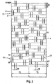
- Fig. 2 is shown in a schematic representation of the development of the lateral surface of the rotary body and the position of the carried by him pairs of clamping elements.
- the in Fig. 1 Depicted epilation head 1 is associated with an epilating device with a motor-containing housing and rotatably supported by its axis of rotation 2 in corresponding bearings.
- the housing and the bearing arrangements receiving it are not shown in the drawing for the sake of clarity.
- To initiate the torques of the epilation head 1 is provided with gears 3.
- the epilation head 1 has a multiplicity of clamping elements 4, 5, wherein respectively associated clamping elements form a pair of clamping elements.
- a pair of clamping elements, each forming a pair of tweezers, is always composed of a movable clamping element 4 and a stationary clamping element 5.
- actuating plunger 6 which are mounted longitudinally displaceable within the epilation head parallel to the axis of rotation 2.
- the actuating tappets 6 lie on a concentric to the axis of rotation 2 extending circle and protrude from both end faces of the epilation head by a small amount. They are controlled by arranged laterally of the epilation head 1 cam so that at a certain time or at a certain angular position of the epilation head, a longitudinal displacement of the actuating plunger 6 in the closing direction of the associated clamping elements 4 takes place. On a presentation of this known cam control is omitted at this point.
- the distribution of the clamping element pairs is provided both in the direction of the longitudinal axis 2 and in the circumferential direction of the epilation head evenly with a defined lateral offset in the longitudinal direction and by a certain angular rotation in the circumferential direction , This is in Fig. 2 detailed and clearly presented.
- the strip-shaped clamping elements 4, 5 are funnel-shaped at their circumferentially facing extended end portions 8 in order to improve the detection and threading of hair. Between these end portions 8 is the clamping region 9, with which contact the two clamping elements when they are in the closed position. In the open state, the clamping regions 9, which extend over a width B, of a pair of clamping elements 4, 5 are separated from one another by the opening width W.
- Fig. 2 illustrated development of the lateral surface of the rotary body, the distribution of the plurality of pairs of clamping elements 4, 5 can be seen.
- the pairs of clamping elements are arranged with a defined lateral offset from each other.
- This lateral offset of axially successive pairs of clamping elements for example, the tweezers 10 and 11 corresponds approximately to the thickness of a strip-shaped clamping element. This in turn is slightly smaller than the opening width W.
- Two circumferentially successive pairs of clamping elements for example, the tweezers 12 and 13, are rotated by a certain angle about the rotation axis 2 against each other.
- This angle is 9 ° in the embodiment, which is founded in that a total of 40 pairs of clamping elements 4, 5 are distributed uniformly on the circumference.
- the epilation head 1 In the axial extent of the epilation head 1 is composed of two equal parts T1 and T2, whose extension corresponds to half of the active Zupfin L. In each of the sections, the distribution of the tweezers is uniform both in the circumferential direction and in the axial direction. The pairs of clamping elements 4, 5 of each portion are each rotated by 18 ° from each other. The rotation between the two subregions T1 and T2 is 9 °. As a result of this distribution, tweezers operated in chronological succession, such as tweezers 12 and 13, for example, are assigned to different partial regions T1 and T2.
- the lateral (axial) distance between the two inner pairs of clamping elements is even somewhat reduced, resulting in a particularly high efficiency in the central region. This is advantageous when plucking individual hairs because the user controls them intuitively with the middle area.
- the width B of the clamping elements is chosen so that in the circumferential direction successive tweezers - for example, the tweezers 12 and 13 - overlap circumferentially.
- the sum of the tweezer width of all 40 tweezers is significantly greater than the circumference of the epilation head.
Landscapes
- Surgical Instruments (AREA)
- Harvester Elements (AREA)
- Hair Curling (AREA)
Description
- Die Erfindung betrifft einen Epilationskopf für ein Epilationsgerät, der als um seine Längsachse drehbar gelagerter Drehkörper mit einer Vielzahl von innerhalb seiner aktiven Zupflänge entlang seiner Längsachse verteilt angeordneten Paaren von Klemmelementen ausgebildet ist.
- Ein solcher Epilationskopf ist beispielsweise aus der
WO 98/05234 - Die einzelnen Klemmelementenpaare bewegen sich während der Rotation des Drehzylinders auf parallel zueinander verlaufenden Kreisbahnen, die seitlich, also in Richtung der Längsachse des Drehzylinders voneinander beabstandet sind. Während der Rotation des Drehzylinders erreichen die Pinzetten die sogenannte Zupfzone in geöffnetem Zustand, in welchem ihre beiden Klemmelemente um die Öffnungsweite voneinander beabstandet sind. Sobald eine definierte Winkellage erreicht ist, werden die Pinzetten durch entsprechende Betätigungselemente aufeinander zu bewegt und in Klemmkontakt gebracht. Dieser Schließzeitpunkt bzw. Schließwinkel ist für sämtliche Pinzetten identisch.
- Aufgrund des seitlichen Abstandes zwischen den Bewegungsbahnen der einzelnen Pinzetten ist die Überdeckung seiner aktiven Zupflänge, also des durch die beiden äußeren Pinzetten begrenzten Bereiches, nicht komplett. Um auch zwischen den Bewegungsebenen der Pinzetten liegende Haare diesen Pinzetten zuzuführen, ist die Mantelfläche des Drehzylinders mit schräg verlaufenden Einfädelnuten versehen, die die Haare in Richtung der Pinzetten derart auslenken, dass sie durch die Klemmelemente erfaßt werden können.
- Zwar stellen Epilationsgeräte mit derartigen Epilationsköpfen zur Zeit die Spitzenprodukte zur Haarentfernung dar, jedoch ist es unter Umständen nötig, Hautpartien mehrmals zu überfahren, bis wirklich kein einziges Haar mehr auf dieser Hautfläche verbleibt. Auch bereiten die Auszupfvorgänge von Haaren, welche durch die Einfädelnuten den Pinzetten zugeführt wurden, gelegentlich Probleme im Hinblick auf das Schmerzempfinden, da sie während des Auszupfens schräg zur Hautoberfläche gezogen werden, was in Bezug auf eine Schmerzvermeidung oder zumindestens eine Schmerzverringerung nicht die optimale Voraussetzung ist.
- Aus der
EP 0 513 900 A2 ist ein Epilationskopf der eingangs genannten Art bekannt, allerdings ist aufgrund der zu berücksichtigenden Dicke der Klemmelemente selbst die Summe der Öffnungsweiten sämtlicher Paare von Klemmelementen kleiner als die Zupflänge des Epilationskopfes. - Des Weiteren ist aus der
WO 01/95758 A1 - Der Erfindung liegt daher die Aufgabe zugrunde, einen Epilationskopf der eingangs genannten Art sowohl in Bezug auf Effizienz als auch in Bezug auf Schmerzreduktion noch weiter zu verbessern. Diese Aufgabe wird erfindungsgemäß durch die Merkmale des Anspruchs 1 gelöst. Vorteilhaft in Bezug auf die Realisierung eines Baukastenprinzipes mit einer Vielzahl einander entsprechender Einzelelemente ist es, wenn der Drehkörper aus mehreren axial hintereinander angeordneten Teilabschnitten gebildet ist, und dass zeitlich aufeinanderfolgend (solche) Paare von Klemmelementen, die unterschiedlichen Teilabschnitten zugeordnet sind, in Klemmkontakt gebracht werden. Dies hat zur Folge, dass zeitlich aufeinanderfolgende Zupfereignisse um ein Mindestmaß örtlich auseinanderliegen, wodurch sich eine Verminderung des subjektiv empfundenen Schmerzes realisieren läßt.
- In Bezug auf eine bestmögliche Schmerzverhinderung bzw. Schmerzminimierung während des Auszupfvorganges ist es von Vorteil, wenn die Betätigung der Klemmelemente derart erfolgt, dass zu einem bestimmten Zeitpunkt lediglich ein einziges, der Vielzahl von Paaren von Klemmelementen in Klemmkontakt gebracht wird. Es hat sich nämlich gezeigt, dass durch eine zeitlich aufeinanderfolgende Verteilung der einzelnen Zupfereignisse das subjektive Schmerzempfinden deutlich geringer ist, als beim gleichzeitigen Auftreten mehrerer Zupfereignisse. Dabei ist es in Bezug auf die Schmerzminimierung ausgesprochen wichtig, dass der zeitliche Abstand zwischen einzelnen Zupfereignissen möglichst gering ist.
- Durch die erfindungsgemäße Lösung läßt sich eine komplette Überdeckung der Umlaufbahnen sämtlicher Klemmelementenpaare erzielen, so dass während des einmaligen Überfahrens eines zu epilierenden Hautabschnittes mit allerhöchster Wahrscheinlichkeit sämtliche darauf vorhandenen Haare ausgezupft werden. Ein mehrfaches Überfahren ein und derselben Stelle ist damit nicht mehr nötig, wodurch der Komfort für den Benutzer deutlich erhöht wird. Dadurch, dass jede Stelle entlang der aktiven Zupflänge durch ein Klemmelementenpaar überfahren wird, ist es möglich, die Haare optimal und möglichst nahe an der Haarwurzel klemmend zu erfassen, und mit einer geraden, möglichst senkrecht zur Hautoberfläche verlaufenden Auszupfbewegung herauszuzupfen. Dadurch wird das Auftreten des Auszupfschmerzes nahezu verhindert. Auf längere Einfädelnuten, durch die das Haar um einen beträchtlichen Betrag seitlich ausgelenkt wird, um durch die Pinzetten erfaßt zu werden, kann dadurch verzichtet werden; allenfalls empfiehlt es sich, relativ kleine trichterförmige Zuführhilfen im Einlaufbereich vor den Klemmelementenpaaren anzuordnen. Es seit an dieser Stelle darauf hingewiesen, dass im Rahmen der vorliegenden Erfindung unter dem Begriff Öffnungsweite der Abstand zwischen den Kontaktbereichen bzw. Kontakt- oder Greifzone einander zugeordneter und eine Pinzette bildender Klemmelemente in geöffnetem Zustand verstanden wird. Diese Öffnungsweite ist unabhängig davon, ob die Klemmelemente mit radial oder in Umfangsrichtung verlaufenden Fortsätzen ausgestattet sind, welche sich trichterförmig in Richtung der Längsachse des Drehkörpers erweitern, und die die Aufgabe haben, das Zuführen der auszuzupfenden Haare zur Klemmstelle zu verbessern.
- Eine vorteilhafte Weiterbildung der Erfindung sieht vor, dass der Epilationskopf mehrere Drehkörper aufweist, und dass die Summe der Öffnungsweiten aller Paare von Klemmelementen mindestens der Summe der aktiven Zupflängen aller Drehkörper des Epilationskopfes entspricht. Dadurch läßt sich auf vergleichsweise einfache Art und ohne besonders hohen Aufwand eine Vielfachüberdeckung des Epilationsbereiches mit den Klemmelementenpaaren erreichen.
- Eine weitere vorteilhafte Ausführungsform der Erfindung sieht vor, dass die Klemmelemente mit gleichmäßigem axialem Abstand über die Zupflänge verteilt sind. Dadurch läßt sich der Epilationskopf unter Verwendung einer Vielzahl von baugleichen Konstruktionsteilen insbesondere von Konstruktionsscheiben mit dazwischen angeordneten Klemmelementen aufbauen. Der Erreichung dieses Zieles dient auch eine Ausführungsform, bei welcher die Klemmelemente gleichmäßig über den Umfang des Drehkörpers verteilt angeordnet sind. Ein solcher Aufbau läßt sich beispielsweise dadurch erreichen, dass baugleiche Scheibenelemente jeweils um einen bestimmten Winkelbetrag versetzt zueinander zu einem im wesentlichen zylinderförmigen Drehkörper montiert werden.
- Eine mehr als 100%ige Abdeckung der aktiven Zupflänge des Epilationskopfes läßt sich gemäß einer weiteren Ausführungsform der Erfindung auch dadurch erreichen, dass der seitliche Versatz zwischen in Richtung der Längsachse des Drehkörpers aufeinanderfolgenden Paaren von Klemmelementen geringer ist als die Öffnungsweite. Dadurch lassen sich überlappende Umlaufbahnen der einzelnen Pinzetten realisieren, was zu einer deutlichen Steigerung der Effizienz des Epilationsgerätes führt. Um eine größtmögliche Anzahl von Klemmelementen auf dem Drehkörper integrieren zu können, ist es von großem Vorteil, wenn in Umfangsrichtung des Drehkörpers aufeinanderfolgende Klemmelementenpaare sich in der Umfangsrichtung überlappen.
- Vorteilhafterweise sind die Klemmelemente, die den einzelnen Teilabschnitten zugeordnet sind, in axialer Richtung und/oder in Umfangsrichtung gleichmäßig verteilt angeordnet.
- Weitere Ziele, Merkmale, Vorteile und Anwendungsmöglichkeiten der vorliegenden Erfindung ergeben sich aus der nachfolgenden Beschreibung des Ausführungsbeispiels. Dabei bilden alle beschriebenen oder bildlich dargestellten Merkmale für sich oder in beliebiger Kombination den Gegenstand vorliegender Erfindung, auch unabhängig von ihrer Zusammenfassung in den Ansprüchen oder deren Rückbeziehung.
- Es zeigt hierzu
Fig. 1 in perspektivischer Darstellung die Ansicht eines erfindungsgemäßen Epilationskopfes, - in
Fig. 2 ist in schematischer Darstellung die Abwicklung der Mantelfläche des Drehkörpers und die Lage der von ihm getragenen Paare von Klemmelementen gezeigt. - Der in
Fig. 1 dargestellte Epilationskopf 1 ist einem Epilationsgerät mit einem einen Motor beinhaltenden Gehäuse zugeordnet und mittels seiner Drehachse 2 in entsprechenden Lagern drehbar gelagert. Das Gehäuse sowie die ihn aufnehmenden Lageranordnungen sind der Übersichtlichkeit halber zeichnerisch nicht dargestellt. Zur Einleitung der Drehmomente ist der Epilationskopf 1 mit Zahnrädern 3 versehen. Der Epilationskopf 1 weist eine Vielzahl von Klemmelementen 4, 5 auf, wobei jeweils einander zugeordnete Klemmelemente ein Klemmelementenpaar bilden. Ein Klemmelementenpaar, das jeweils eine Pinzette bildet, setzt sich stets aus einem bewegbaren Klemmelement 4 und einem stationären Klemmelement 5 zusammen. Die Betätigung des beweglichen Klemmelementes 4 erfolgt in an sich aus derWO 98/05234 - Die Klemmelemente 4 bzw. 5 befinden sich jeweils paarweise zwischen axial hintereinander angeordneten Scheibenelementen 7. Die Verteilung der Klemmelementepaare ist sowohl in Richtung der Längsachse 2 als auch in Umfangsrichtung des Epilationskopfes gleichmäßig mit einem definierten seitlichen Versatz in Längsrichtung sowie um eine bestimmte Winkelverdrehung in Umfangsrichtung vorgesehen. Dies ist in
Fig. 2 ausführlich und übersichtlich dargestellt. - Die streifenförmigen Klemmelemente 4, 5 sind an ihren in Umfangsrichtung weisenden erweiterten Endabschnitten 8 trichterförmig aufgebogen, um das Erfassen und Einfädeln von Haaren zu verbessern. Zwischen diesen Endabschnitten 8 liegt der Klemmbereich 9, mit welchem sich die beiden Klemmelemente kontaktieren, wenn sie sich in Schließstellung befinden. In geöffnetem Zustand sind die sich über eine Breite B erstreckenden Klemmbereiche 9 eines Paares von Klemmelementen 4, 5 um die Öffnungsweite W voneinander entfernt.
- Aus der in
Fig. 2 dargestellten Abwicklung der Mantelfläche des Drehkörpers ist die Verteilung der Vielzahl von Paaren von Klemmelementen 4, 5 zu entnehmen. In axialer Richtung der Drehachse 2 sind die Paare von Klemmelementen mit einem definierten seitlichen Versatz zueinander angeordnet. Dieser seitliche Versatz von in axialer Richtung aufeinanderfolgenden Paaren von Klemmelementen, beispielsweise der Pinzette 10 und 11 entspricht etwa der Dicke eines streifenförmigen Klemmelements. Diese wiederum ist etwas geringer als die Öffnungsweite W. - Zwei in Umfangsrichtung aufeinanderfolgende Klemmelementenpaare, beispielsweise die Pinzetten 12 und 13, sind um einen bestimmten Winkel um die Drehachse 2 gegeneinander verdreht. Dieser Winkel beträgt im Ausführungsbeispiel 9°, was darin gegründet ist, dass insgesamt 40 Paare von Klemmelementen 4, 5 gleichmäßig am Umfang verteilt vorgesehen sind.
- In axialer Erstreckung setzt sich der Epilationskopf 1 aus zwei gleich großen Teilbereichen T1 und T2 zusammen, deren Erstreckung der Hälfte der aktiven Zupflänge L entspricht. In jedem der Teilbereiche ist die Verteilung der Pinzetten sowohl in Umfangsrichtung ,als auch in axialer Richtung gleichmäßig. Die Paare von Klemmelementen 4 , 5 jedes Teilbereiches sind jeweils um 18° gegeneinander verdreht. Die Verdrehung zwischen den beiden Teilbereichen T1 und T2 ist 9°. Durch diese Verteilung ergibt es sich, dass zeitlich nacheinander betätigte Pinzetten, wie beispielsweise die Pinzetten 12 und 13 unterschiedlichen Teilbereichen T1 bzw. T2 zugeordnet sind.
- An der Übergangsstelle zwischen den beiden Teilbereichen T1 und T2 ist der seitliche (axiale) Abstand zwischen den beiden innenliegenden Klemmelementenpaaren sogar etwas verringert, wodurch sich eine besonders hohe Effizienz im Mittelbereich ergibt. Dies ist beim Auszupfen einzelner Haare von Vorteil, da der Benutzer diese intuitiv mit dem Mittelbereich ansteuert.
- Da der seitliche bzw. axiale Versatz der Pinzetten geringer oder maximal gleich groß der Öffnungsweite W ist, wird die gesamte aktive Zupflänge L durch die Umlaufbahnen der Klemmelementpaare 4, 5 abgedeckt. Ist der axiale Versatz geringer als die Öffnungsweite W, so überlappen sich die Umlaufbahnen sogar. Aufgrund der in
Fig. 2 dargestellten geometrischen Anordnung der Klemmelemente 4, 5 ist die Summe der Öffnungsweiten W sämtlicher 40 Paare von Klemmelementen größer als die aktive Zupflänge L. - Die Breite B der Klemmelemente ist so gewählt, dass sich in Umfangsrichtung aufeinanderfolgende Pinzetten - beispielsweise die Pinzetten 12 und 13 - umfangsmäßig überlappen. Die Summe der Pinzettenbreite sämtlicher 40 Pinzetten ist deutlich größer, als der Umfang des Epilationskopfes.
- Aufgrund der mindestens 100%igen Abdeckung der aktiven Zupflänge L durch die Paare von Klemmelelenten wird ein hocheffizientes Epilieren ermöglicht. Diese Effizienz läßt sich nochmals steigern, wenn das Epilationsgerät mit mehreren solcher Epilationsköpfe, die parallel zueinanderliegend angeordnet sind, ausgestattet ist. Eine solche Anordnung ist zeichnerisch nicht dargestellt.
Claims (9)
- Epilationskopf (1) für ein Epilationsgerät, der als um seine Längsachse (2) drehbar gelagerter Drehkörper mit einer Vielzahl von innerhalb seiner aktiven Zupflänge (L) entlang seiner Längsachse (2) verteilt angeordneten Paaren (10, 11, 12, 13) von Klemmelementen (4, 5) ausgebildet ist, und der Betätigungselemente (6) aufweist, um die Klemmelemente (4, 5) paarweise in Klemmkontakt zueinander zu bringen und sie anschließend wieder zu öffnen, um Haare zwischen den Klemmelementen (4, 5) einzuklemmen und auszuzupfen, wobei die Paare von Klemmelementen in geöffnetem Zustand jeweils eine Öffnungsweite (W) zwischen ihren Klemmbereichen (9) aufweisen und die Summe der Öffnungsweite (W) aller Paare von Klemmelementen (4, 5) mindestens der aktiven Zupflänge (L) des Epilationskopfes (1) entspricht, wobei der Drehkörper (1) aus mehreren axial hintereinander angeordneten Teilabschnitten (T1, T2) gebildet ist, und zeitlich aufeinanderfolgend Paare von Klemmelementen (4,5) die unterschiedlichen Teilabschnitten (T1, T2) zugeordnet sind, in Klemmkontakt gebracht werden, dadurch gekennzeichnet, dass die Betätigung der Klemmelemente (4, 5) derart erfolgt, dass zu einem Zeitpunkt lediglich ein einziges der Klemmelemente (4, 5) in Klemmkontakt gebracht wird.
- Epilationskopf nach Anspruch 1, dadurch gekennzeichnet, dass er mehrere Drehkörper (1) aufweist, und dass die Summe der Öffnungsweiten (W) aller Paare (11-13) von Klemmelementen (4, 5) mindestens der Summe der aktiven Zupflänge (L) aller Drehkörper (1) des Epilationskopfes entspricht.
- Epilationskopf nach Anspruch 1 oder 2, dadurch gekennzeichnet, dass die Summe der Öffnungsweiten (W) aller Paare von Klemmelementen (4, 5) größer ist als die aktive Zupflänge (L) des Epilationskopfes (1).
- Epilationskopf nach einem der vorhergehenden Ansprüche, dadurch gekennzeichnet, dass die Klemmelemente (4, 5) mit im wesentlichen gleichmäßigem axialen Abstand über die aktive Zupflänge (L) verteilt sind.
- Epilationskopf nach einem der vorhergehenden Ansprüche, dadurch gekennzeichnet, dass die Klemmelemente (4, 5) gleichmäßig über den Umfang des Drehkörpers (1) verteilt angeordnet sind.
- Epilationskopf nach einem der vorhergehenden Ansprüche, dadurch gekennzeichnet, dass der seitliche Versatz zwischen in Richtung der Längsachse (2) des Drehkörpers (1) aufeinanderfolgenden Paaren (10, 11) von Klemmelementen (4, 5) kleiner oder gleich der Öffnungsweite (W) ist.
- Epilationskopf nach einem der vorhergehenden Ansprüche, dadurch gekennzeichnet, dass in Umfangsrichtung des Drehkörpers (1) aufeinanderfolgende Paare (10, 12, 13) von Klemmelementen (4, 5) sich in der Umfangsrichtung überlappen.
- Epilationskopf nach einem der vorhergehenden Ansprüche, dadurch gekennzeichnet, dass die Klemmelelente (4, 5) eines Teilabschnittes (T1, T2) mit gleichmäßigem axialem Abstand verteilt angeordnet sind.
- Epilationskopf nach Anspruch 8, dadurch gekennzeichnet, dass die Klemmelemente (4, 5) eines Teilabschnittes (T1, T2) gleichmäßig über dessen Umfang verteilt angeordnet sind.
Applications Claiming Priority (2)
| Application Number | Priority Date | Filing Date | Title |
|---|---|---|---|
| DE10318749A DE10318749A1 (de) | 2003-04-25 | 2003-04-25 | Epilationskopf für ein Epilationsgerät |
| PCT/EP2004/003900 WO2004095973A1 (de) | 2003-04-25 | 2004-04-14 | Epilationskopf für ein epilationsgerät |
Publications (2)
| Publication Number | Publication Date |
|---|---|
| EP1617742A1 EP1617742A1 (de) | 2006-01-25 |
| EP1617742B1 true EP1617742B1 (de) | 2008-04-02 |
Family
ID=33304942
Family Applications (1)
| Application Number | Title | Priority Date | Filing Date |
|---|---|---|---|
| EP04727276A Expired - Lifetime EP1617742B1 (de) | 2003-04-25 | 2004-04-14 | Epilationskopf für ein epilationsgerät |
Country Status (7)
| Country | Link |
|---|---|
| US (1) | US20060271071A1 (de) |
| EP (1) | EP1617742B1 (de) |
| JP (1) | JP4660467B2 (de) |
| AT (1) | ATE390863T1 (de) |
| DE (2) | DE10318749A1 (de) |
| ES (1) | ES2303943T3 (de) |
| WO (1) | WO2004095973A1 (de) |
Cited By (1)
| Publication number | Priority date | Publication date | Assignee | Title |
|---|---|---|---|---|
| CN106723866A (zh) * | 2012-10-12 | 2017-05-31 | 博朗有限公司 | 脱毛器 |
Families Citing this family (7)
| Publication number | Priority date | Publication date | Assignee | Title |
|---|---|---|---|---|
| EP1857012A1 (de) * | 2006-05-18 | 2007-11-21 | Faco S.A. | Monolithisches Epilationsgerät |
| US20080077160A1 (en) * | 2006-09-27 | 2008-03-27 | Hoangmy Thi Nhan | Pain free electrical waxing hairs remover |
| EP2127552B1 (de) | 2008-05-27 | 2017-08-02 | Braun GmbH | Haarentfernungsvorrichtung |
| JP4720887B2 (ja) | 2008-09-22 | 2011-07-13 | パナソニック電工株式会社 | 脱毛装置 |
| JP4720886B2 (ja) * | 2008-09-22 | 2011-07-13 | パナソニック電工株式会社 | 脱毛装置 |
| ES2639299T3 (es) * | 2013-04-16 | 2017-10-26 | Braun Gmbh | Accesorio para depiladora y depiladora |
| USD763505S1 (en) * | 2013-09-19 | 2016-08-09 | Braun Gmbh | Epilator |
Family Cites Families (12)
| Publication number | Priority date | Publication date | Assignee | Title |
|---|---|---|---|---|
| ES2081554T3 (es) * | 1991-05-13 | 1996-03-16 | Philips Electronics Nv | Aparato de depilacion con dientes de empuje. |
| US5196021A (en) * | 1992-02-25 | 1993-03-23 | Perfect Lady Ltd. | Depilatory device |
| US5281233A (en) * | 1993-02-12 | 1994-01-25 | Moshe Dolev | Disc assembly hair remover |
| TR199900236T2 (xx) * | 1996-08-06 | 1999-04-21 | Braun Aktiengesellschaft | Epilasyon aleti i�in d�ner silindir. |
| JP3864627B2 (ja) * | 1999-07-27 | 2007-01-10 | 松下電工株式会社 | 脱毛装置 |
| JP3873550B2 (ja) * | 1999-11-25 | 2007-01-24 | 松下電工株式会社 | 脱毛装置 |
| US6585743B2 (en) * | 2000-06-09 | 2003-07-01 | Moshe Dolev | Hair depilating device utilizing mechanism to spirally align coupled-tweezer elements |
| FR2810216B1 (fr) * | 2000-06-15 | 2002-08-16 | Seb Sa | Appareil a epiler a pinces portees par une chaine |
| JP2002159327A (ja) * | 2000-11-27 | 2002-06-04 | Matsushita Electric Works Ltd | 脱毛装置 |
| TW557208B (en) * | 2001-05-28 | 2003-10-11 | Matsushita Electric Works Ltd | Molting apparatus |
| JP4026413B2 (ja) * | 2001-05-28 | 2007-12-26 | 松下電工株式会社 | 脱毛装置 |
| AT7332U1 (de) * | 2002-07-11 | 2005-02-25 | Payer Int Technologies Gmbh | Epilationsgerät |
-
2003
- 2003-04-25 DE DE10318749A patent/DE10318749A1/de not_active Ceased
-
2004
- 2004-04-14 WO PCT/EP2004/003900 patent/WO2004095973A1/de not_active Ceased
- 2004-04-14 AT AT04727276T patent/ATE390863T1/de not_active IP Right Cessation
- 2004-04-14 JP JP2006505112A patent/JP4660467B2/ja not_active Expired - Lifetime
- 2004-04-14 ES ES04727276T patent/ES2303943T3/es not_active Expired - Lifetime
- 2004-04-14 DE DE502004006720T patent/DE502004006720D1/de not_active Expired - Lifetime
- 2004-04-14 US US10/554,432 patent/US20060271071A1/en not_active Abandoned
- 2004-04-14 EP EP04727276A patent/EP1617742B1/de not_active Expired - Lifetime
Cited By (2)
| Publication number | Priority date | Publication date | Assignee | Title |
|---|---|---|---|---|
| CN106723866A (zh) * | 2012-10-12 | 2017-05-31 | 博朗有限公司 | 脱毛器 |
| CN106723866B (zh) * | 2012-10-12 | 2020-12-11 | 博朗有限公司 | 脱毛器 |
Also Published As
| Publication number | Publication date |
|---|---|
| ES2303943T3 (es) | 2008-09-01 |
| EP1617742A1 (de) | 2006-01-25 |
| WO2004095973A1 (de) | 2004-11-11 |
| JP2006524521A (ja) | 2006-11-02 |
| JP4660467B2 (ja) | 2011-03-30 |
| DE502004006720D1 (de) | 2008-05-15 |
| US20060271071A1 (en) | 2006-11-30 |
| DE10318749A1 (de) | 2004-11-18 |
| ATE390863T1 (de) | 2008-04-15 |
Similar Documents
| Publication | Publication Date | Title |
|---|---|---|
| DE68928647T2 (de) | Enthaarungsgerät | |
| EP0921744B1 (de) | Drehzylinder für ein epilationsgerät | |
| EP0610412B1 (de) | Diffusor für einen haartrockner | |
| EP2266434B1 (de) | Kosmetik-Applikator mit innenliegenden, herausschiebbaren, drehbaren Applikatoren | |
| DE68908070T2 (de) | Gerät zum Enthaaren. | |
| DE4427788C2 (de) | Epilationsgerät zum Entfernen von Haaren am menschlichen Körper | |
| DE69001782T2 (de) | Enthaarungsgeraet. | |
| DE69821807T2 (de) | Haarentfernungsgerät mit drehbarer Rolle | |
| EP1581074B1 (de) | Aufsatz für ein epiliergerät | |
| DE3930884A1 (de) | Geraet zum auszupfen von haaren | |
| EP1617742A1 (de) | Epilationskopf für ein epilationsgerät | |
| DE69101278T2 (de) | Enthaarungsgerät. | |
| DE69105384T3 (de) | Enthaarungsgerät mit Bürste. | |
| DE102008014946A1 (de) | Enthaarungsvorrichtung | |
| EP1796499B1 (de) | Epilationskopf und epilationsgerät | |
| EP0547386B1 (de) | Epilationsgerät | |
| WO2005039348A1 (de) | Epilationsgerät | |
| EP0642311B1 (de) | Epilationsgerät | |
| EP1521538B1 (de) | Epilationsgerät | |
| EP0569614A1 (de) | Haarzupfgerät | |
| AT7333U1 (de) | Epilationskopf für ein epilationsgerät | |
| WO1997037781A1 (de) | Reinigungsvorrichtung mit winchesterverstellung | |
| EP1478254B1 (de) | Epilationsgerät | |
| WO1993009694A1 (de) | Enthaarungsgerät |
Legal Events
| Date | Code | Title | Description |
|---|---|---|---|
| PUAI | Public reference made under article 153(3) epc to a published international application that has entered the european phase |
Free format text: ORIGINAL CODE: 0009012 |
|
| 17P | Request for examination filed |
Effective date: 20050915 |
|
| AK | Designated contracting states |
Kind code of ref document: A1 Designated state(s): AT BE BG CH CY CZ DE DK EE ES FI FR GB GR HU IE IT LI LU MC NL PL PT RO SE SI SK TR |
|
| AX | Request for extension of the european patent |
Extension state: AL HR LT LV MK |
|
| DAX | Request for extension of the european patent (deleted) | ||
| 17Q | First examination report despatched |
Effective date: 20061205 |
|
| GRAP | Despatch of communication of intention to grant a patent |
Free format text: ORIGINAL CODE: EPIDOSNIGR1 |
|
| GRAS | Grant fee paid |
Free format text: ORIGINAL CODE: EPIDOSNIGR3 |
|
| GRAA | (expected) grant |
Free format text: ORIGINAL CODE: 0009210 |
|
| AK | Designated contracting states |
Kind code of ref document: B1 Designated state(s): AT BE BG CH CY CZ DE DK EE ES FI FR GB GR HU IE IT LI LU MC NL PL PT RO SE SI SK TR |
|
| REG | Reference to a national code |
Ref country code: GB Ref legal event code: FG4D Free format text: NOT ENGLISH |
|
| REG | Reference to a national code |
Ref country code: CH Ref legal event code: EP Ref country code: IE Ref legal event code: FG4D Free format text: LANGUAGE OF EP DOCUMENT: GERMAN Ref country code: CH Ref legal event code: NV Representative=s name: LUCHS & PARTNER PATENTANWAELTE |
|
| REF | Corresponds to: |
Ref document number: 502004006720 Country of ref document: DE Date of ref document: 20080515 Kind code of ref document: P |
|
| REG | Reference to a national code |
Ref country code: ES Ref legal event code: FG2A Ref document number: 2303943 Country of ref document: ES Kind code of ref document: T3 |
|
| PG25 | Lapsed in a contracting state [announced via postgrant information from national office to epo] |
Ref country code: SI Free format text: LAPSE BECAUSE OF FAILURE TO SUBMIT A TRANSLATION OF THE DESCRIPTION OR TO PAY THE FEE WITHIN THE PRESCRIBED TIME-LIMIT Effective date: 20080402 |
|
| REG | Reference to a national code |
Ref country code: IE Ref legal event code: FD4D |
|
| PG25 | Lapsed in a contracting state [announced via postgrant information from national office to epo] |
Ref country code: PT Free format text: LAPSE BECAUSE OF FAILURE TO SUBMIT A TRANSLATION OF THE DESCRIPTION OR TO PAY THE FEE WITHIN THE PRESCRIBED TIME-LIMIT Effective date: 20080903 Ref country code: FI Free format text: LAPSE BECAUSE OF FAILURE TO SUBMIT A TRANSLATION OF THE DESCRIPTION OR TO PAY THE FEE WITHIN THE PRESCRIBED TIME-LIMIT Effective date: 20080402 Ref country code: BG Free format text: LAPSE BECAUSE OF FAILURE TO SUBMIT A TRANSLATION OF THE DESCRIPTION OR TO PAY THE FEE WITHIN THE PRESCRIBED TIME-LIMIT Effective date: 20080702 |
|
| PG25 | Lapsed in a contracting state [announced via postgrant information from national office to epo] |
Ref country code: PL Free format text: LAPSE BECAUSE OF FAILURE TO SUBMIT A TRANSLATION OF THE DESCRIPTION OR TO PAY THE FEE WITHIN THE PRESCRIBED TIME-LIMIT Effective date: 20080402 Ref country code: MC Free format text: LAPSE BECAUSE OF NON-PAYMENT OF DUE FEES Effective date: 20080430 |
|
| ET | Fr: translation filed | ||
| PG25 | Lapsed in a contracting state [announced via postgrant information from national office to epo] |
Ref country code: SE Free format text: LAPSE BECAUSE OF FAILURE TO SUBMIT A TRANSLATION OF THE DESCRIPTION OR TO PAY THE FEE WITHIN THE PRESCRIBED TIME-LIMIT Effective date: 20080702 Ref country code: EE Free format text: LAPSE BECAUSE OF FAILURE TO SUBMIT A TRANSLATION OF THE DESCRIPTION OR TO PAY THE FEE WITHIN THE PRESCRIBED TIME-LIMIT Effective date: 20080402 Ref country code: CZ Free format text: LAPSE BECAUSE OF FAILURE TO SUBMIT A TRANSLATION OF THE DESCRIPTION OR TO PAY THE FEE WITHIN THE PRESCRIBED TIME-LIMIT Effective date: 20080402 Ref country code: DK Free format text: LAPSE BECAUSE OF FAILURE TO SUBMIT A TRANSLATION OF THE DESCRIPTION OR TO PAY THE FEE WITHIN THE PRESCRIBED TIME-LIMIT Effective date: 20080402 Ref country code: IE Free format text: LAPSE BECAUSE OF FAILURE TO SUBMIT A TRANSLATION OF THE DESCRIPTION OR TO PAY THE FEE WITHIN THE PRESCRIBED TIME-LIMIT Effective date: 20080402 |
|
| PLBE | No opposition filed within time limit |
Free format text: ORIGINAL CODE: 0009261 |
|
| STAA | Information on the status of an ep patent application or granted ep patent |
Free format text: STATUS: NO OPPOSITION FILED WITHIN TIME LIMIT |
|
| PG25 | Lapsed in a contracting state [announced via postgrant information from national office to epo] |
Ref country code: RO Free format text: LAPSE BECAUSE OF FAILURE TO SUBMIT A TRANSLATION OF THE DESCRIPTION OR TO PAY THE FEE WITHIN THE PRESCRIBED TIME-LIMIT Effective date: 20080402 Ref country code: SK Free format text: LAPSE BECAUSE OF FAILURE TO SUBMIT A TRANSLATION OF THE DESCRIPTION OR TO PAY THE FEE WITHIN THE PRESCRIBED TIME-LIMIT Effective date: 20080402 |
|
| 26N | No opposition filed |
Effective date: 20090106 |
|
| PG25 | Lapsed in a contracting state [announced via postgrant information from national office to epo] |
Ref country code: CY Free format text: LAPSE BECAUSE OF FAILURE TO SUBMIT A TRANSLATION OF THE DESCRIPTION OR TO PAY THE FEE WITHIN THE PRESCRIBED TIME-LIMIT Effective date: 20080402 |
|
| PG25 | Lapsed in a contracting state [announced via postgrant information from national office to epo] |
Ref country code: LU Free format text: LAPSE BECAUSE OF NON-PAYMENT OF DUE FEES Effective date: 20080414 Ref country code: HU Free format text: LAPSE BECAUSE OF FAILURE TO SUBMIT A TRANSLATION OF THE DESCRIPTION OR TO PAY THE FEE WITHIN THE PRESCRIBED TIME-LIMIT Effective date: 20081003 |
|
| PGFP | Annual fee paid to national office [announced via postgrant information from national office to epo] |
Ref country code: AT Payment date: 20100315 Year of fee payment: 7 |
|
| PG25 | Lapsed in a contracting state [announced via postgrant information from national office to epo] |
Ref country code: GR Free format text: LAPSE BECAUSE OF FAILURE TO SUBMIT A TRANSLATION OF THE DESCRIPTION OR TO PAY THE FEE WITHIN THE PRESCRIBED TIME-LIMIT Effective date: 20080703 |
|
| REG | Reference to a national code |
Ref country code: AT Ref legal event code: MM01 Ref document number: 390863 Country of ref document: AT Kind code of ref document: T Effective date: 20110414 |
|
| PG25 | Lapsed in a contracting state [announced via postgrant information from national office to epo] |
Ref country code: AT Free format text: LAPSE BECAUSE OF NON-PAYMENT OF DUE FEES Effective date: 20110414 |
|
| PGFP | Annual fee paid to national office [announced via postgrant information from national office to epo] |
Ref country code: CH Payment date: 20130426 Year of fee payment: 10 Ref country code: BE Payment date: 20130424 Year of fee payment: 10 |
|
| REG | Reference to a national code |
Ref country code: CH Ref legal event code: PL |
|
| PG25 | Lapsed in a contracting state [announced via postgrant information from national office to epo] |
Ref country code: LI Free format text: LAPSE BECAUSE OF NON-PAYMENT OF DUE FEES Effective date: 20140430 Ref country code: CH Free format text: LAPSE BECAUSE OF NON-PAYMENT OF DUE FEES Effective date: 20140430 |
|
| REG | Reference to a national code |
Ref country code: FR Ref legal event code: PLFP Year of fee payment: 13 |
|
| REG | Reference to a national code |
Ref country code: FR Ref legal event code: PLFP Year of fee payment: 14 |
|
| PG25 | Lapsed in a contracting state [announced via postgrant information from national office to epo] |
Ref country code: BE Free format text: LAPSE BECAUSE OF NON-PAYMENT OF DUE FEES Effective date: 20140430 |
|
| REG | Reference to a national code |
Ref country code: FR Ref legal event code: PLFP Year of fee payment: 15 |
|
| PGFP | Annual fee paid to national office [announced via postgrant information from national office to epo] |
Ref country code: IT Payment date: 20180420 Year of fee payment: 15 Ref country code: TR Payment date: 20180412 Year of fee payment: 15 |
|
| PG25 | Lapsed in a contracting state [announced via postgrant information from national office to epo] |
Ref country code: IT Free format text: LAPSE BECAUSE OF NON-PAYMENT OF DUE FEES Effective date: 20190414 |
|
| PG25 | Lapsed in a contracting state [announced via postgrant information from national office to epo] |
Ref country code: TR Free format text: LAPSE BECAUSE OF NON-PAYMENT OF DUE FEES Effective date: 20190414 |
|
| PGFP | Annual fee paid to national office [announced via postgrant information from national office to epo] |
Ref country code: FR Payment date: 20230309 Year of fee payment: 20 |
|
| PGFP | Annual fee paid to national office [announced via postgrant information from national office to epo] |
Ref country code: GB Payment date: 20230302 Year of fee payment: 20 |
|
| P01 | Opt-out of the competence of the unified patent court (upc) registered |
Effective date: 20230430 |
|
| PGFP | Annual fee paid to national office [announced via postgrant information from national office to epo] |
Ref country code: NL Payment date: 20230314 Year of fee payment: 20 |
|
| PGFP | Annual fee paid to national office [announced via postgrant information from national office to epo] |
Ref country code: ES Payment date: 20230511 Year of fee payment: 20 Ref country code: DE Payment date: 20230307 Year of fee payment: 20 |
|
| REG | Reference to a national code |
Ref country code: DE Ref legal event code: R071 Ref document number: 502004006720 Country of ref document: DE |
|
| REG | Reference to a national code |
Ref country code: NL Ref legal event code: MK Effective date: 20240413 |
|
| PG25 | Lapsed in a contracting state [announced via postgrant information from national office to epo] |
Ref country code: ES Free format text: LAPSE BECAUSE OF EXPIRATION OF PROTECTION Effective date: 20240415 |
|
| REG | Reference to a national code |
Ref country code: ES Ref legal event code: FD2A Effective date: 20240426 |
|
| PG25 | Lapsed in a contracting state [announced via postgrant information from national office to epo] |
Ref country code: ES Free format text: LAPSE BECAUSE OF EXPIRATION OF PROTECTION Effective date: 20240415 |
|
| REG | Reference to a national code |
Ref country code: GB Ref legal event code: PE20 Expiry date: 20240413 |
|
| PG25 | Lapsed in a contracting state [announced via postgrant information from national office to epo] |
Ref country code: GB Free format text: LAPSE BECAUSE OF EXPIRATION OF PROTECTION Effective date: 20240413 |
|
| PG25 | Lapsed in a contracting state [announced via postgrant information from national office to epo] |
Ref country code: GB Free format text: LAPSE BECAUSE OF EXPIRATION OF PROTECTION Effective date: 20240413 |