EP1616336B1 - Kerntechnische anlage und verfahren zum betrieb einer kerntechnischen anlage - Google Patents
Kerntechnische anlage und verfahren zum betrieb einer kerntechnischen anlage Download PDFInfo
- Publication number
- EP1616336B1 EP1616336B1 EP04739084A EP04739084A EP1616336B1 EP 1616336 B1 EP1616336 B1 EP 1616336B1 EP 04739084 A EP04739084 A EP 04739084A EP 04739084 A EP04739084 A EP 04739084A EP 1616336 B1 EP1616336 B1 EP 1616336B1
- Authority
- EP
- European Patent Office
- Prior art keywords
- cooling liquid
- overflow
- chamber
- condensation chamber
- separation
- Prior art date
- Legal status (The legal status is an assumption and is not a legal conclusion. Google has not performed a legal analysis and makes no representation as to the accuracy of the status listed.)
- Expired - Lifetime
Links
- 238000000034 method Methods 0.000 title claims description 8
- 239000000110 cooling liquid Substances 0.000 claims abstract description 57
- 230000005494 condensation Effects 0.000 claims abstract description 51
- 238000009833 condensation Methods 0.000 claims abstract description 51
- 238000001816 cooling Methods 0.000 claims abstract description 28
- 238000000926 separation method Methods 0.000 claims description 63
- 239000007788 liquid Substances 0.000 claims description 10
- 230000000630 rising effect Effects 0.000 claims description 3
- 238000005192 partition Methods 0.000 description 15
- 239000002826 coolant Substances 0.000 description 10
- 239000012809 cooling fluid Substances 0.000 description 9
- 238000009434 installation Methods 0.000 description 7
- 238000009835 boiling Methods 0.000 description 6
- XLYOFNOQVPJJNP-UHFFFAOYSA-N water Substances O XLYOFNOQVPJJNP-UHFFFAOYSA-N 0.000 description 6
- 230000001052 transient effect Effects 0.000 description 5
- 230000005526 G1 to G0 transition Effects 0.000 description 4
- 238000005086 pumping Methods 0.000 description 4
- 238000011161 development Methods 0.000 description 3
- 230000018109 developmental process Effects 0.000 description 3
- 239000000498 cooling water Substances 0.000 description 2
- 230000007423 decrease Effects 0.000 description 2
- 230000001419 dependent effect Effects 0.000 description 2
- 239000002245 particle Substances 0.000 description 2
- 239000002689 soil Substances 0.000 description 2
- 238000009825 accumulation Methods 0.000 description 1
- 230000009194 climbing Effects 0.000 description 1
- 230000002950 deficient Effects 0.000 description 1
- 238000005057 refrigeration Methods 0.000 description 1
Images
Classifications
-
- G—PHYSICS
- G21—NUCLEAR PHYSICS; NUCLEAR ENGINEERING
- G21C—NUCLEAR REACTORS
- G21C9/00—Emergency protection arrangements structurally associated with the reactor, e.g. safety valves provided with pressure equalisation devices
- G21C9/004—Pressure suppression
-
- G—PHYSICS
- G21—NUCLEAR PHYSICS; NUCLEAR ENGINEERING
- G21C—NUCLEAR REACTORS
- G21C15/00—Cooling arrangements within the pressure vessel containing the core; Selection of specific coolants
- G21C15/18—Emergency cooling arrangements; Removing shut-down heat
-
- Y—GENERAL TAGGING OF NEW TECHNOLOGICAL DEVELOPMENTS; GENERAL TAGGING OF CROSS-SECTIONAL TECHNOLOGIES SPANNING OVER SEVERAL SECTIONS OF THE IPC; TECHNICAL SUBJECTS COVERED BY FORMER USPC CROSS-REFERENCE ART COLLECTIONS [XRACs] AND DIGESTS
- Y02—TECHNOLOGIES OR APPLICATIONS FOR MITIGATION OR ADAPTATION AGAINST CLIMATE CHANGE
- Y02E—REDUCTION OF GREENHOUSE GAS [GHG] EMISSIONS, RELATED TO ENERGY GENERATION, TRANSMISSION OR DISTRIBUTION
- Y02E30/00—Energy generation of nuclear origin
- Y02E30/30—Nuclear fission reactors
Definitions
- the invention relates to a nuclear installation, in particular a boiling water reactor system and a method for operating the system.
- a flood basin is provided as a reservoir for cooling liquid, which is used in case of need for cooling the reactor.
- the flood basin is usually arranged such that the coolant flows solely by gravitational forces and without the use of active components, such as pumps, to the desired location.
- a condensation chamber is still provided, which is an important part of the cooling system of a modern boiling water reactor plant.
- the cooling system is designed to control a loss-of-coolant accident where large amounts of steam can be released within the containment in the so-called pressure chamber. The released steam is passed into the condensation chamber for condensation.
- the Framatome ANP is provided with a passively acting system which requires no external power supply and no active components.
- a plurality of condensation tubes are provided, which release a flow path in the condensation chamber above a certain pressure in the pressure chamber and thus allow the introduction of the vapor into the condensation chamber.
- this cooling system it is therefore necessary that an overpressure builds up in the pressure chamber.
- the condensation chamber must be sealed gas-tight with respect to the pressure chamber, so that the steam is reliably ensured via the condensation tube.
- the invention has for its object to ensure reliable operation of the nuclear facility.
- the object is achieved according to the invention by a nuclear installation, in particular boiling water reactor installation, with the features according to claim 1.
- This embodiment is based on the idea to introduce cold cooling water for cooling the cooling liquid in the flood basin and to dispense with a separate cooling circuit for the cooling liquid of the flood basin.
- the excess, warm cooling liquid is supplied via the overflow device of the condensation chamber.
- This measure eliminates the need for the arrangement of a separate cooling circuit for the cooling liquid of the flood basin.
- To cool the cooling water can be made of a cooling circuit for the Kondensationskammmer.
- the apparatus the necessary installation space and thus the erfoderlichen costs are kept low.
- the flood basin communicates with the pressure chamber, ie in the flood basin and in the pressure chamber prevail the same pressure conditions. In this case, entrainment of gas components into the condensation chamber would lead to an increase in the pressure in the condensation chamber. This is disadvantageous in terms of the functioning of the cooling system.
- the overflow device is designed for gas separation from the liquid. Thus, an undesirable increase in pressure in the condensation chamber is safely avoided.
- the flood basin comprises a reservoir and a separation well separated by an overflow enabling first partition wall. Furthermore, an overflow line is provided, whose first orifice is arranged in the lower region of the separation shaft.
- the coolant of the flood basin is stored.
- the liquid level rises until the cooling liquid overflows over the first dividing wall into the separation shaft and accumulates there. Since the cooling liquid is discharged via the first orifice, which is preferably arranged in the immediate vicinity of the soil or directly in the soil, the risk of gas entrainment is reduced. Because possibly existing gas parts can - before they get into the overflow pipe - ascend and escape from the cooling liquid.
- the overflow device for a maximum overflow mass flow is designed such that when this maximum overflow mass flow occurs, the overflow line has a predetermined flow resistance, so that a backflow of the cooling liquid is formed in the separation shaft up to a backflow height correlating to the flow resistance.
- This refinement is based on the consideration of adjusting the flow resistance of the overflow line, for example, by selecting the flow cross section such that a predetermined backflow is formed in the separation shaft, so that the cooling liquid remains in the separation shaft for a sufficiently long time before it is guided via the overflow line into the condensation chamber so that gas particles present in the cooling liquid can outgas from the cooling liquid.
- the flow cross-sectional area of the separation shaft is designed such that the downward speed of the back-flown liquid is less than the rate of rise of gas bubbles of predetermined size.
- Downward speed is understood to mean the average downward speed.
- the downward speed of Back-stagnant liquid ie the average velocity with which a liquid volume moves in the direction of the first orifice opening, is essentially determined by the flow cross-sectional area of the separation shaft.
- the buoyancy force caused by the buoyancy force of the gas bubbles is significantly dependent on their size (diameter).
- the overflow device is designed such that even in the absence of a mass flow, ie at zero flow, the liquid is present in the separation shaft up to a minimum backwater level.
- This embodiment is based on the consideration that during startup or termination of the supply of cold coolant in the flood basin unsteady phases occur in which the liquid mass accumulation increases from zero flow to the maximum mass flow and drops again to the zero flow rate. During these transient phases, until the complete mass flow rate has been reached, the cooling liquid in the separation shaft must first be collected or removed again up to the maximum backwater level.
- the overflow line is designed to set the minimum backwater height in the manner of a siphon with an upper siphon, through which the minimum backwater height is determined.
- the separation shaft comprises in its bottom region a separation chamber and a discharge chamber, which are separated by a second partition wall enabling an overflow.
- the first mouth opening the overflow line is arranged in the outflow chamber.
- the cooling liquid which falls down into the separation shaft is collected, so that it can calm down there and possibly even the first gas bubbles can escape.
- the cooling liquid then flows with only slight turbulence and largely gas-free into the discharge chamber, so that even in the transient phases, a gas transfer into the condensation chamber is avoided.
- a common cooling circuit which comprises the overflow device.
- This common cooling circuit is formed in particular by a pumping line, a pump and a heat exchanger.
- the pumping line leads from the condensation chamber to the flood basin so that, in the circulation principle, the cooling liquid is returned from the condensation chamber into the flood basin and from there back into the condensation chamber. Excess heat is dissipated via the provided heat exchanger of the common cooling circuit. Due to the common cooling circuit both for the cooling liquid of the flood basin and for the condensation chamber eliminates the need for two separate cooling circuits. Thus, the necessary installation space and thus the cost is kept low.
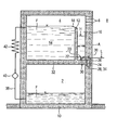
- FIG. 1 shows a roughly simplified section of a containment of a Siederwasserreaktorstrom.
- a condensation chamber 2 as well as a flood basin 4 arranged above the condensation chamber 2 are shown as parts of the containment vessel.
- the flood basin 4 and the condensation chamber 2 are preferably arranged together in the interior of the containment.
- the flood basin 4 is connected via an open connection 6 with the designated as pressure chamber 8 interior of the containment, so that between the pressure chamber 8 and the flood basin 4, a gas exchange and thus a pressure equalization takes place.
- the condensation chamber 2 and the flood basin 4 are separated from each other by a wall structure 10 made of concrete, wherein the condensation chamber 2 is sealed gas-tight to the flood basin 4 and the pressure chamber 8 during normal operation of the system.
- the flood basin 4 and the condensation chamber are part of a cooling system, which further comprises a condensation pipe, not shown here.
- the cooling system is also designed for the control of a coolant loss accident, in which large amounts of steam can occur in the pressure chamber, which are introduced via the condensation tube into the cooling liquid F of the condensation chamber 2.
- the flood basin 4 is divided by a first partition wall 12 into a storage tank 14 and a separation shaft 16.
- the storage tank 14 stores the cooling liquid F provided for emergency cooling.
- At the upper end of the first partition wall 12 is an overflow edge 18. For a possible turbulence-free overflow of the cooling fluid F, this is formed obliquely.
- a second partition wall 20 is arranged, which divides the bottom area into a separation chamber 22 adjoining the first partition wall 12 and a drainage chamber 24.
- a first mouth opening 26 of an overflow line 28 is arranged.
- Whose second orifice 30 is disposed in the upper region of the condensation chamber 2 and in particular directly on or in the ceiling 32.
- the overflow line 28 is designed in the manner of a siphon with a lower siphon bend 34 and an upper siphon bend 36.
- the overflow line 28 is preferably a simple pipeline without further fittings and runs in particular almost completely in the wall structure 10. The flow path formed by the overflow line 28 thus remains functional even with a defective pipeline.
- the separation shaft 16 with the overflow edge 18 of the separation chamber 22 and the discharge chamber 24 and the overflow line 28 form an overflow device for excess cooling fluid F.
- This overflow device is part of a common cooling circuit for the flooding tank 4 and the condensation chamber 2 located in the cooling fluid F.
- This common cooling circuit has in addition to the overflow device a pump line 38, a pump 40 and a heat exchanger 42, via the pumping line 38 cooling fluid F from the Condensation chamber 2 can be pumped into the flood basin 4 via the heat exchanger 40.
- Cooling of the cooling fluid F in the flood basin 4 is required from time to time due to heat input during normal operation of the system.
- cooling liquid F is pumped out of the condensation chamber 2 through the heat exchanger 42 via the common cooling circuit, cooled and then introduced into the reservoir 14. If the fill level in the reservoir 16 exceeds the maximum fill level defined by the overflow edge 18, the excess coolant F passes via the overflow edge 18 into the separation shaft 16 and from there via the overflow line 28 back into the condensation chamber 2.
- the mass flow of the excess cooling liquid F, which enters the separation shaft 16 increases continuously until the maximum mass flow is reached and a stationary phase is formed.
- the flow resistance of the overflow line 28 is set to a certain value for this maximum mass flow, so that the cooling liquid F in the separation shaft is backed up to a maximum backflow height H.
- This maximum backwater height H is for example a few meters and is approximately at 2/3 of the height of the first partition wall 12 and the height of the overflow edge 18th
- the mass flow decreases again, until finally no excess cooling fluid F more in the separation shaft 16 passes (zero flow).
- the height of the backflowed cooling fluid F decreases continuously until a minimum backflow height L is reached in the separation shaft 16.
- This minimal backwater height L is defined by the height of the upper siphon bend 36. Slightly above this, a slightly higher level is established in the separation chamber 22, since the second partition wall 20 has a height above the minimum fill level H.
- the minimum backwater height L is, for example, 0.5 m.
- an average downward speed of the back-flowed cooling fluid F sets.
- This downward speed is an amount for the speed with which a volume of liquid thought in the separation chute 16 reaches the overflow line 28.
- this downward speed is largely determined by the flow cross-sectional area A of the separation shaft 16. Gas particles entrained in the separation shaft 16 form overflow in the cooling liquid F gas bubbles which rise upward in the back-flowed liquid at a rate of rise due to the buoyancy force.
- the downward speed and the climbing speed are therefore directed in opposite directions. The rate of climb depends on the size of the gas bubbles.
- the flow cross-sectional area A of the separation shaft is now set, for example, over several square meters such that the Rising speed of gas bubbles of a predetermined size, for example, a diameter of 1 mm, is greater than the downward speed. This ensures that these gas bubbles rise faster than coolant F reaches the overflow line 28.
- the second stage of the gas separation is provided, which is essentially formed from the separation chamber 22 and the discharge chamber 24.
- the cooling liquid F falling over the overflow edge 18 is first collected and collected until it is largely free via the second dividing wall 20 overflowed by turbulence.
- the separation chamber 22 so there is already a large part of the gas separation.
- the height of the second partition wall 20 and the minimum backwater height L in the discharge chamber 24 have only small differences, for example, of a few centimeters, so that in the discharge chamber 24 no greater turbulence is generated and no gas entry takes place. From the outflow chamber 24 then passes the largely gas-free cooling liquid F via the overflow line 28 into the condensation chamber 2 via.
Landscapes
- Physics & Mathematics (AREA)
- Engineering & Computer Science (AREA)
- Plasma & Fusion (AREA)
- General Engineering & Computer Science (AREA)
- High Energy & Nuclear Physics (AREA)
- Structure Of Emergency Protection For Nuclear Reactors (AREA)
- Greenhouses (AREA)
- Casting Devices For Molds (AREA)
- Apparatuses For Bulk Treatment Of Fruits And Vegetables And Apparatuses For Preparing Feeds (AREA)
- Molds, Cores, And Manufacturing Methods Thereof (AREA)
- Filling Or Discharging Of Gas Storage Vessels (AREA)
- Pressure Vessels And Lids Thereof (AREA)
Description
- Die Erfindung betrifft eine kerntechnische Anlage, insbesondere eine Siedewasserreaktoranlage sowie ein Verfahren zum Betrieb der Anlage.
- Bei einer modernen Siedewasserreaktoranlage ist ein Flutbecken als Reservoir für Kühlflüssigkeit vorgesehen, die im Bedarfsfall zur Kühlung des Reaktors eingesetzt wird. Das Flutbecken ist dabei üblicherweise derart angeordnet, dass das Kühlmittel allein durch Gravitationskräfte und ohne Einsatz von aktiven Komponenten, wie beispielsweise Pumpen, zum gewünschten Ort strömt. Bei der Siedewasserreaktoranlage ist weiterhin eine Kondensationskammer vorgesehen, die ein wichtiger Bestandteil des Kühlsystems einer modernen Siedewasserreaktoranlage ist. Das Kühlsystem ist zur Beherrschung eines Kühlmittelverluststörfalls ausgelegt, bei dem große Dampfmengen innerhalb des Sicherheitsbehälters in der so genannten Druckkammer freigesetzt werden können. Der freigesetzte Dampf wird zur Kondensation in die Kondensationskammer geleitet. Hierzu ist beispielsweise bei dem SWR1000-Konzept der Framatome ANP ein passiv wirkendes System vorgesehen, welches ohne externe Energiezufuhr und ohne aktive Komponenten auskommt. Und zwar sind mehrere Kondensationsrohre vorgesehen, welche ab einem bestimmten Überdruck in der Druckkammer einen Strömungsweg in die Kondensationskammer freigeben und somit die Einleitung des Dampfes in die Kondensationskammer ermöglichen. Für die Funktionsfähigkeit dieses Kühlsystems ist es daher notwendig, dass sich in der Druckkammer ein Überdruck aufbaut. In anderen Worten, die Kondensationskammer muss gasdicht gegenüber der Druckkammer abgeschlossen sein, so dass die Dampfeinleitung über das Kondensationsrohr sicher gewährleistet ist.
- Beim Normalbetrieb wird dem Kühlmittel im Flutbecken Wärme zugeführt, so dass das Kühlmittel in regelmäßigen Zeitabständen gekühlt werden muss. Hierfür ist üblicherweise ein eigener Kühlkreislauf vorgesehen.
- Der Erfindung liegt die Aufgabe zugrunde, einen zuverlässigen Betrieb der kerntechnischen Anlage zu gewährleisten.
- Die Aufgabe wird gemäß der Erfindung gelöst durch eine kerntechnische Anlage, insbesondere Siedewasserreaktoranlage, mit den Merkmalen gemäß Anspruch 1.
- Dieser Ausgestaltung liegt die Überlegung zugrunde, zur Kühlung der Kühlflüssigkeit im Flutbecken kaltes Kühlwasser einzuleiten und dabei auf einen separaten Kühlkreislauf für die Kühlflüssigkeit des Flutbeckens zu verzichten. Die überschüssige, warme Kühlflüssigkeit wird über die Überlaufeinrichtung der Kondensationskammer zugeführt. Durch diese Maßnahme entfällt die Notwendigkeit der Anordnung eines separaten Kühlkreislaufs für die Kühlflüssigkeit des Flutbeckens. Zur Abkühlung des Kühlwassers kann auf einen Kühlkreislauf für die Kondensationskammmer zurückgegriffen werden. Der apparative Aufwand, der notwendige Einbauraum und damit die erfoderlichen Kosten sind gering gehalten. Außerdem entfällt die Notwendigkeit, dem Füllstand im Flutbecken zu regeln.
- Bei der Überleitung der Kühlflüssigkeit aus dem Flutbecken in die Kondensationskammer besteht die Gefahr, dass Gasteile vom Flutbecken mit in die Kondensationskammer gerissen werden. Üblicherweise steht das Flutbecken mit der Druckkammer in Verbindung, d.h. im Flutbecken und in der Druckkammer herrschen die gleichen Druckverhältnisse. Ein Mitreißen von Gasteilen in die Kondensationskammer würde in diesem Fall dazu führen, dass sich der Druck in der Kondensationskammer erhöht. Dies ist im Hinblick auf die Funktionsfähigkeit des Kühlsystems von Nachteil. In einer bevorzugten Weiterbildung ist daher vorgesehen, dass die Überlaufeinrichtung zur Gasabscheidung aus der Flüssigkeit ausgebildet ist. Somit ist eine unerwünschte Druckerhöhung in der Kondensationskammer sicher vermieden.
- Zweckdienlicherweise umfasst das Flutbecken ein Speicherbecken und einen Separationsschacht, die durch eine einen Überlauf ermöglichende erste Trennwand getrennt sind. Weiterhin ist eine Überlaufleitung vorgesehen, deren erste Mündungsöffnung im unteren Bereich des Separationsschachts angeordnet ist.
- Im Speicherbecken ist die Kühlflüssigkeit des Flutbeckens bevorratet. Bei Zuführung von Kühlflüssigkeit steigt der Flüssigkeitsspiegel an, bis die Kühlflüssigkeit über die erste Trennwand in den Separationsschacht überläuft und sich dort ansammelt. Da die Kühlflüssigkeit über die erste Mündungsöffnung, die vorzugsweise in unmittelbarer Nähe des Bodens oder direkt im Boden angeordnet ist, abgeleitet wird, ist die Gefahr der Gasmitnahme verringert. Denn evtl. vorhandene Gasteile können - bevor sie in die Überlaufleitung gelangen - aufsteigen und aus der Kühlflüssigkeit austreten.
- In einer zweckdienlichen Ausgestaltung ist die Überlaufeinrichtung für einen maximalen Überlauf-Massestrom derart ausgebildet, dass bei Auftreten dieses maximalen Überlauf-Massestroms die Überlaufleitung einen vorbestimmten Strömungswiderstand aufweist, so dass sich im Separationsschacht ein Rückstau der Kühlflüssigkeit bis zu einer zum Strömungswiderstand korrelierenden Rückstauhöhe ausbildet.
- Dieser Ausgestaltung liegt die Überlegung zugrunde, den Strömungswiderstand der Überlaufleitung beispielsweise durch die Wahl des Strömungsquerschnitts derart einzustellen, dass sich im Separationsschacht ein vorbestimmter Rückstau ausbildet, so dass die Kühlflüssigkeit, bevor sie über die Überlaufleitung in die Kondensationskammer geführt wird, im Separationsschacht ausreichend lange verweilt, damit in der Kühlflüssigkeit vorhandene Gasteilchen aus der Kühlflüssigkeit ausgasen können.
- Vorzugsweise ist die Strömungsquerschnittsfläche des Separationsschachts derart ausgebildet, dass die Abwärtsgeschwindigkeit der rückgestauten Flüssigkeit kleiner als die Steiggeschwindigkeit von Gasblasen vorgegebener Größe ist. Unter Abwärtsgeschwindigkeit wird hierbei die mittlere Abwärtsgeschwindigkeit verstanden. Im Falle eines konstanten Massenstroms im stationären Fall ist die dem Separationsschacht zu- und abgeführte Menge an Kühlflüssigkeit identisch ist. Die Abwärtsgeschwindigkeit der rückgestauten Flüssigkeit, also die mittleren Geschwindigkeit, mit der sich ein Flüssigkeitsvolumen in Richtung zu der ersten Mündungsöffnung bewegt, ist dabei im Wesentlichen von der Strömungsquerschnittsfläche des Separationsschachts bestimmt. Andererseits ist die durch die Auftriebskraft bedingte Auftriebsgeschwindigkeit der Gasblasen maßgeblich von deren Größe (Durchmesser) abhängig. Durch die gezielte Einstellung der Abwärtsgeschwindigkeit kleiner als die Steiggeschwindigkeit der Gasblasen steigen letztere schneller auf als die Kühlflüssigkeit absinkt, so dass die Gasblasen die erste Mündungsöffnung der Überlaufleitung nicht erreichen.
- In einer zweckdienlichen Weiterbildung ist die Überlaufeinrichtung derart ausgebildet, dass selbst bei Fehlen eines Massestroms, also bei einem Nulldurchsatz, die Flüssigkeit im Separationsschacht bis zu einer minimalen Rückstauhöhe ansteht. Dieser Ausgestaltung liegt die Überlegung zugrunde, dass beim Ingangsetzen bzw. Beenden der Zuführung von kalter Kühlflüssigkeit in das Flutbecken instationäre Phasen auftreten, bei denen der Flüssigkeitsmassenstau vom Nulldurchsatz zum maximalen Massenstrom ansteigt bzw. wieder auf den Nulldurchsatz abfällt. Während dieser instationären Phasen muss bis zum Erreichen des vollständigen Massendurchsatzes die Kühlflüssigkeit im Separationsschacht erst bis zur maximalen Rückstauhöhe angesammelt bzw. wieder abgebaut werden. In diesen instationären Phasen stürzt die Kühlflüssigkeit über eine große Fallhöhe in den Separationsschacht und es besteht die Gefahr, dass erhebliche Gasmengen mitgerissen werden, die in Ermangelung eines Rückstaus unter Umständen direkt in die Überlaufleitung und somit in die Kondensationskammer gelangen könnten. Diese Gefahr wird durch die Gewährleistung einer minimalen Rückstauhöhe im Separationsschacht verringert.
- Zweckdienlicherweise ist zur Einstellung der minimalen Rückstauhöhe die Überlaufleitung nach Art eines Siphons mit einem oberen Siphonbogen ausgebildet, durch den die minimale Rückstauhöhe bestimmt ist.
- Gemäß einer bevorzugten Weiterbildung umfasst der Separationsschacht in seinem Bodenbereich eine Separationskammer und eine Abflusskammer, die durch eine einen Überlauf ermöglichende zweite Trennwand getrennt sind. Die erste Mündungsöffnung der Überlaufleitung ist hierbei in der Abflusskammer angeordnet. In der Separationskammer wird zunächst die in den Separationsschacht herabstürzende Kühlflüssigkeit gesammelt, so dass sie sich dort beruhigen kann und evtl. schon die ersten Gasblasen austreten können. Von der Separationskammer läuft die Kühlflüssigkeit dann mit nur geringen Turbulenzen und weitgehend gasfrei in die Abflusskammer, so dass auch bei den instationären Phasen ein Gasübertritt in die Kondensationskammer vermieden ist.
- Für die Kühlflüssigkeit des Flutbeckens und die Kühlflüssigkeit der Kondensationskammer ist ein gemeinsamer Kühlkreislauf vorgesehen, welcher die Überlaufeinrichtung umfasst. Dieser gemeinsame Kühlkreislauf ist dabei insbesondere durch eine Pumpleitung, eine Pumpe und einen Wärmetauscher gebildet. Die Pumpleitung führt von der Kondensationskammer zum Flutbecken, so dass im Umwälzprinzip die Kühlflüssigkeit aus der Kondensationskammer in das Flutbecken und von dort wieder in die Kondensationskammer zurückgeführt wird. Über den vorgesehenen Wärmetauscher des gemeinsamen Kühlkreislaufs wird überschüssige Wärme abgeführt. Durch den gemeinsamen Kühlkreislauf sowohl für die Kühlflüssigkeit des Flutbeckens als auch für die der Kondensationskammer entfällt die Notwendigkeit zweier separater Kühlkreisläufe. Damit werden der notwendige Einbauraum und somit der Kostenaufwand gering gehalten.
- Die Aufgabe wird gemäß der Erfindung weiterhin gelöst durch ein Verfahren zum Betrieb einer kerntechnischen Anlage, insbesondere einer Siedewasserreaktoranlage, mit den Merkmalen gemäß Patentanspruch 10. Die im Hinblick auf die Anlage angegebenen Vorteile und bevorzugten Ausführungsvarianten sind sinngemäß auch auf das Verfahren anzuwenden. Bevorzugte Weiterbildungen sind zudem in den abhängigen Ansprüchen niedergelegt.
- Ein Ausführungsbeispiel der Erfindung wird im Folgenden anhand der einzigen Figur näher erläutert. Diese Figur zeigt einen grob vereinfachten Ausschnitt eines Sicherheitsbehälters einer Siederwasserreaktoranlage.
- In der Figur sind als Teile des Sicherheitsbehälters eine Kondensationskammer 2 sowie ein über der Kondensationskammer 2 angeordnetes Flutbecken 4 dargestellt. Das Flutbecken 4 und die Kondensationskammer 2 sind vorzugsweise gemeinsam im Innenraum des Sicherheitsbehälters angeordnet. Das Flutbecken 4 ist über eine offene Verbindung 6 mit dem als Druckkammer 8 bezeichneten Innenraum des Sicherheitsbehälters verbunden, so dass zwischen der Druckkammer 8 und dem Flutbecken 4 ein Gasaustausch und somit ein Druckausgleich stattfindet. Die Kondensationskammer 2 und das Flutbecken 4 sind durch eine Wandstruktur 10 aus Beton voneinander getrennt, wobei die Kondensationskammer 2 zum Flutbecken 4 und zur Druckkammer 8 während des Normalbetriebs der Anlage gasdicht verschlossen ist. Das Flutbecken 4 und die Kondensationskammer sind Teil eines Kühlsystems, welches weiterhin ein hier nicht dargestelltes Kondensationsrohr umfasst. Das Kühlsystem ist auch für die Beherrschung eines Kühlmittelverluststörfalls ausgelegt, bei dem in der Druckkammer große Dampfmengen auftreten können, die über das Kondensationsrohr in die Kühlflüssigkeit F der Kondensationskammer 2 eingeleitet werden.
- Das Flutbecken 4 ist durch eine erste Trennwand 12 unterteilt in ein Speicherbecken 14 und einen Separationsschacht 16. Im Speicherbecken 14 ist die für eine Notkühlung vorgesehene Kühlflüssigkeit F bevorratet. Am oberen Ende der ersten Trennwand 12 befindet sich eine Überlaufkante 18. Für einen möglichst turbulenzfreien Überlauf der Kühlflüssigkeit F ist diese schräg verlaufend ausgebildet. Am Boden des Separationsschachts 16 ist eine zweite Trennwand 20 angeordnet, die den Bodenbereich in eine sich an die erste Trennwand 12 anschließende Separationskammer 22 und eine Abflusskammer 24 unterteilt. Im Bodenbereich der Abflusskammer 24 ist eine erste Mündungsöffnung 26 einer Überlaufleitung 28 angeordnet. Deren zweite Mündungsöffnung 30 ist im oberen Bereich der Kondensationskammer 2 und insbesondere unmittelbar am oder in deren Decke 32 angeordnet. Die Überlaufleitung 28 ist nach Art eines Siphons mit einem unteren Siphonbogen 34 und einem oberen Siphonbogen 36 ausgebildet. Die Überlaufleitung 28 ist vorzugsweise eine einfache Rohrleitung ohne weiteren Einbauten und verläuft insbesondere nahezu vollständig in der Wandstruktur 10. Der durch die Überlaufleitung 28 gebildete Strömungsweg bleibt somit auch bei einer schadhaften Rohrleitung funktionstüchtig. Der Separationsschacht 16 mit der Überlaufkante 18 der Separationskammer 22 und der Abflusskammer 24 sowie die Überlaufleitung 28 bilden eine Überlaufeinrichtung für überschüssige Kühlflüssigkeit F.
- Diese Überlaufeinrichtung ist Teil eines gemeinsamen Kühlkreislaufs für die im Flutbecken 4 und in der Kondensationskammer 2 befindliche Kühlflüssigkeit F. Dieser gemeinsame Kühlkreislauf weist neben der Überlaufeinrichtung eine Pumpleitung 38, eine Pumpe 40 sowie einen Wärmetauscher 42 auf, wobei über die Pumpleitung 38 Kühlflüssigkeit F aus der Kondensationskammer 2 in das Flutbecken 4 über den Wärmetauscher 40 gepumpt werden kann. Durch die Bereitstellung eines gemeinsamen Kühlkreislaufs entfällt die Notwendigkeit der Anordnung von mehreren separaten Kühlkreisläufen. Dadurch sind die Installationskosten und der benötigte Bauraum gering gehalten.
- Eine Kühlung der Kühlflüssigkeit F im Flutbecken 4 ist von Zeit zu Zeit aufgrund eines Wärmeeintrags beim normalen Betrieb der Anlage erforderlich. Hierzu wird über den gemeinsamen Kühlkreislauf Kühlflüssigkeit F aus der Kondensationskammer 2 durch den Wärmetauscher 42 gepumpt, dabei abgekühlt und anschließend in das Speicherbecken 14 eingeleitet. Übersteigt die Füllstandshöhe im Speicherbecken 16 die durch die Überlaufkante 18 definierte maximale Füllstandshöhe, läuft die überschüssige Kühlflüssigkeit F über die Überlaufkante 18 in den Separationsschacht 16 über und von dort über die Überlaufleitung 28 wieder zurück in die Kondensationskammer 2.
- Bei der Rückführung der Kühlflüssigkeit F in die Kondensationskammer 2 ist die Einleitung von Gasteilen zu vermeiden, da ansonsten ein unerwünschter Druckanstieg in der Kondensationskammer 2, verbunden mit einem entsprechenden Druckabfall in der Druckkammer 8, erfolgen würde. Daher ist die Überlaufeinrichtung zur Abscheidung von Gasteilen, die sich in der überschüssigen Kühlflüssigkeit F befinden, ausgebildet. Die Gasabscheidung wird hierbei insbesondere durch den speziellen Aufbau des Separationsschachts 16 gewährleistet. Durch die beiden Trennwände 12,20 ist hierbei eine zweistufige Gasabscheidung vorgesehen, wobei die durch die zweite Trennwand 20 gebildete zweite Stufe insbesondere bei kleinen Massenströmen wirksam ist. Das Funktionsprinzip der Gasabscheidung ist wie folgt:
- Beim Beginn der Umwälzung der Kühlflüssigkeit F steigt während einer instationären Phase der Massenstrom der überschüssigen Kühlflüssigkeit F, die in den Separationsschacht 16 gelangt, kontinuierlich an, bis der maximale Massenstrom erreicht wird und sich eine stationäre Phase ausbildet. Während dieser stationären Phase ist der dem Separationsschacht 16 zu- und abgeleitete Massenstrom an Kühlflüssigkeit F identisch. Der Strömungswiderstand der Überlaufleitung 28 ist für diesen maximalen Massestrom auf einen bestimmten Wert eingestellt, so dass sich die Kühlflüssigkeit F im Separationsschacht bis zu einer maximalen Rückstauhöhe H rückstaut. Diese maximale Rückstauhöhe H beträgt beispielsweise einige Meter und liegt etwa auf 2/3 der Höhe der ersten Trennwand 12 bzw. der Höhe der Überlaufkante 18.
- Nach Abschalten der Pumpe 40 verringert sich der Massestrom wieder, bis schließlich keine überschüssige Kühlflüssigkeit F mehr in den Separationsschacht 16 gelangt (Nulldurchsatz). Die Höhe der rückgestauten Kühlflüssigkeit F sinkt kontinuierlich, bis im Separationsschacht 16 eine minimale Rückstauhöhe L erreicht wird. Diese minimale Rückstauhöhe L ist definiert durch die Höhe des oberen Siphonbogens 36. Geringfügig darüber stellt sich in der Separationskammer 22 ein etwas höherer Füllstand ein, da die zweite Trennwand 20 eine Höhe oberhalb der minimalen Füllstandshöhe H aufweist. Die minimale Rückstauhöhe L beträgt beispielsweise 0,5 m.
- Bei der stationären Phase mit dem maximalen Massenstrom stellt sich eine mittlere Abwärtsgeschwindigkeit der rückgestauten Kühlflüssigkeit F ein. Diese Abwärtsgeschwindigkeit ist ein Betrag für die Geschwindigkeit, mit der ein gedachtes Flüssigkeitsvolumen im Separationsschacht 16 in Richtung zur Überlaufleitung 28 gelangt. Im stationären Fall ist diese Abwärtsgeschwindigkeit maßgeblich bestimmt durch die Strömungsquerschnittsfläche A des Separationsschachts 16. Beim Überlauf in den Separationsschacht 16 mitgerissene Gasteilchen bilden in der Kühlflüssigkeit F Gasbläschen, die mit einer durch die Auftriebskraft bedingten Steiggeschwindigkeit in der rückgestauten Flüssigkeit aufwärts steigen. Die Abwärtsgeschwindigkeit und die Steiggeschwindigkeit sind also gegensätzlich gerichtet. Die Steiggeschwindigkeit hängt von der Größe der Gasblasen ab. Die Strömungsquerschnittsfläche A des Separationsschachts ist nunmehr beispielsweise auf mehrere Quadratmeter derart eingestellt, dass die Steiggeschwindigkeit von Gasblasen einer vorgegebenen Größe, beispielsweise eines Durchmessers von 1 mm, größer ist als die Abwärtsgeschwindigkeit. Dadurch ist gewährleistet, dass diese Gasblasen schneller aufsteigen als Kühlflüssigkeit F zur Überlaufleitung 28 gelangt.
- Bei den kleinen Massenströmen während der instationären Phase besteht das Problem, dass aufgrund der größeren Fallhöhe von der Überlaufkante 18 bis zu der dann geringen Höhe der rückgestauten Kühlflüssigkeit F der Gaseintrag und die Turbulenzen in der Kühlflüssigkeit F im Separationsschacht 16 größer sind als bei der stationären Phase. Daher ist die zweite Stufe der Gasabscheidung vorgesehen, die im Wesentlichen gebildet ist aus der Separationskammer 22 und der Abflusskammer 24. In der Separationskammer 22 wird zunächst die über die Überlaufkante 18 herabstürzende Kühlflüssigkeit F aufgefangen und gesammelt, bis sie über die zweite Trennwand 20 weitgehend frei von Turbulenzen überläuft. In der Separationskammer 22 findet also bereits ein großer Teil der Gasabscheidung statt. Beim Überlauf über die zweite Trennwand 20 werden nur geringe Gasanteile mitgerissen. Maßgebend hierfür ist, dass die Höhe der zweiten Trennwand 20 und die minimale Rückstauhöhe L in der Abflusskammer 24 nur geringe Unterschiede beispielsweise von wenigen Zentimetern aufweisen, so dass in der Abflusskammer 24 keine stärkerenTurbulenzen erzeugt werden und kein Gaseintrag stattfindet. Aus der Abflusskammer 24 läuft anschließend die weitgehend gasfreie Kühlflüssigkeit F über die Überlaufleitung 28 in die Kondensationskammer 2 über.
- Durch die Hintereinanderschaltung der ersten und zweiten Trennwand 12,20 mit einer sehr großen Höhe von mehreren Metern bzw. mit einer sehr kleinen Höhe von weniger als 1 m in Verbindung mit der speziellen Dimensionierung des Separationsschachts 16 sowie der Überlaufleitung 16 wird eine effektive Gasabscheidung bewirkt, ohne dass störanfällige aktive Komponenten, wie beispielsweise rotierende oder durch Fremdenergie angetriebene Teile, notwendig werden. Die Gasabscheidung erfolgt daher rein passiv und ist somit nicht störanfällig.
-
- 2
- Kondensationskammer
- 4
- Flutbecken
- 6
- offene Verbindung
- 8
- Druckkammer
- 10
- Wandstruktur
- 12
- erste Trennwand
- 14
- Speicherbecken
- 16
- Separationsschacht
- 18
- Überlaufkante
- 20
- zweite Trennwand
- 22
- Separationskammer
- 24
- Abflusskammer
- 26
- erste Mündungsöffnung
- 28
- Überlaufleitung
- 30
- zweite Mündungsöffnung
- 32
- Decke
- 34
- unterer Siphonbogen
- 36
- oberer Siphonbogen
- 38
- Pumpleitung
- 40
- Pumpe
- 42
- Wärmetauscher
- F
- Kühlflüssigkeit
- H
- Rückstauhöhe
- L
- minimale Rückstauhöhe
- A
- Strömungsquerschnittsfläche
Claims (13)
- Kernreaktoranlage mit einem für die Bevorratung von Kühlflüssigkeit (F) zu Notkühlzwecken vorgesehenen Kernflutbecken (4), mit einer Kondensationskammer (2) und mit einer vom Kernflutbecken (4) zur Kondensationskammer (2) angeordneten Überlaufeinrichtung (16,28) für überschüssige Kühlflüssigkeit (F), wobei für die Kühlflüssigkeit (F) des Flutbeckens (4) und die Kühlflüssigkeit (F) der Kondensationskammer (2) ein gemeinsamer Kühlkreislauf (16,28,38,40,42) vorgesehen ist, welcher die Überlaufeinrichtung (16,28) umfasst.
- Anlage nach Anspruch 1 oder 2, bei der die Überlaufeinrichtung (16,28) zur Gasabscheidung aus der Flüssigkeit (F) ausgebildet ist.
- Anlage nach Anspruch 1 oder 2, bei der das Flutbecken (4) ein Speicherbecken (14) und einen Separationsschacht (16) umfasst, die durch eine einen Überlauf ermöglichende erste Trennwand (12) getrennt sind und wobei eine Überlaufleitung (28) vorgesehen ist, deren erste Mündungsöffnung (26) im unteren Bereich des Separationsschachts (16) angeordnet ist.
- Anlage nach Anspruch 3, bei der die erste Mündungsöffnung (26) im oder in unmittelbarer Nähe des Bodens des Separationsschachts (16) angeordnet ist.
- Anlage nach Anspruch 3 oder 4, bei der die Überlaufeinrichtung (16,28) für einen maximalen Überlauf-Massenstrom derart ausgebildet ist, dass bei Auftreten des maximalen Überlauf-Massenstroms die Überlaufleitung (28) einen vorbestimmten Strömungswiderstand aufweist, so dass sich im Separationsschacht (16) ein Rückstau der Kühlflüssigkeit (F) bis zu einer maximalen Rückstauhöhe (H) ausbildet.
- Anlage nach Anspruch 5, bei der die Strömungsquerschnittsfläche (A) des Separationsschachts (16) derart ausgebildet ist, dass die Abwärtsgeschwindigkeit der rückgestauten Kühlflüssigkeit (F) kleiner als die Steiggeschwindigkeit von Gasblasen vorgegebener Größe ist.
- Anlage nach einem der Ansprüche 3 bis 6, bei der die Überlaufeinrichtung (16,28) derart ausgebildet ist, dass selbst bei Fehlen eines Massestroms die Kühlflüssigkeit (F) im Separationsschacht (16) bis zu einer minimalen Rückstauhöhe (L) ansteht.
- Anlage nach Anspruch 7, bei der die Überlaufleitung (28) nach Art eines Syphons mit einem oberen Syphonbogen (36) ausgebildet ist und die minimale Rückstauhöhe (L) durch den oberen Syphonbogen (36) bestimmt ist.
- Anlage nach einem der Ansprüche 3 bis 8, bei der der Separationsschacht (16) in seinem Bodenbereich eine Separationskammer (27) und eine Abflusskammer (24) umfasst, die durch eine einen Überlauf ermöglichende zweite Trennwand (20) getrennt sind und wobei die erste Mündungsöffnung (26) der Überlaufleitung (28) in der Abflusskammer (24) angeordnet ist.
- Verfahren zum Betrieb einer Kernreaktoranlage, bei dem in vorbestimmten Betriebszuständen einem für die Bevorratung von Kühlflüssigkeit (F) zu Notkühlzwecken vorgesehenen Kernflutbecken (4) eine das Fassungsvermögen desselben übersteigende Menge an Kühlflüssigkeit (F) zugeleitet wird und die überschüssige Kühlflüssigkeit (F) über eine Überlaufeinrichtung (16,28) in eine Kondensationskammer (2) übergeleitet wird, wobei die Kühlflüssigkeit (F) des Flutbeckens (4) und die der Kondensationskammer (2) in einem gemeinsamem Kühlkreislauf (16,28,38,40,42), welcher die Überlaufeinrichtung (16,28) umfasst, geführt werden.
- Verfahren nach Anspruch 10, bei dem aus der überschüssigen Kühlflüssigkeit (F) Gasteile abgeschieden werden.
- Verfahren nach Anspruch 10 oder 11, bei dem die überschüssige Kühlflüsigkeit (F) bei hohen Massenströmen vor dem Übertritt in die Kondensationskammer (2) in einem Separationsschacht (16) zurückgestaut wird und dort die Abscheidung der Gasteile durch Aufsteigen erfolgt.
- Verfahren nach einem der Ansprüche 10 bis 12, bei dem bei geringen Masseströmen die überschüssige Kühlflüssigkeit (F) im Bodenbereich des Separationsschachts (16) zunächst in einer Separationskammer (22) gesammelt und von dort in eine Abflusskammer (24) geleitet wird, aus der die Kühlflüssigkeit (F) in die Kondensationskammer (2) gelangt.
Applications Claiming Priority (3)
| Application Number | Priority Date | Filing Date | Title |
|---|---|---|---|
| DE10318141A DE10318141B4 (de) | 2003-04-16 | 2003-04-16 | Kerntechnische Anlage mit Überlaufeinrichtung zwischen Flutbecken und Kondensationskammer und Verfahren zum Betrieb einer solchen kerntechnischen Anlage |
| DE10318081A DE10318081B4 (de) | 2003-04-16 | 2003-04-16 | Kerntechnische Anlage |
| PCT/EP2004/004109 WO2004093095A2 (de) | 2003-04-16 | 2004-04-16 | Kerntechnische anlage und verfahren zum betrieb einer kerntechnischen anlage |
Publications (2)
| Publication Number | Publication Date |
|---|---|
| EP1616336A2 EP1616336A2 (de) | 2006-01-18 |
| EP1616336B1 true EP1616336B1 (de) | 2008-07-09 |
Family
ID=33300847
Family Applications (2)
| Application Number | Title | Priority Date | Filing Date |
|---|---|---|---|
| EP04739084A Expired - Lifetime EP1616336B1 (de) | 2003-04-16 | 2004-04-16 | Kerntechnische anlage und verfahren zum betrieb einer kerntechnischen anlage |
| EP04727893A Expired - Lifetime EP1616335B1 (de) | 2003-04-16 | 2004-04-16 | Kerntechnische anlage und verfahren zum betrieb einer kerntechnischen anlage |
Family Applications After (1)
| Application Number | Title | Priority Date | Filing Date |
|---|---|---|---|
| EP04727893A Expired - Lifetime EP1616335B1 (de) | 2003-04-16 | 2004-04-16 | Kerntechnische anlage und verfahren zum betrieb einer kerntechnischen anlage |
Country Status (7)
| Country | Link |
|---|---|
| US (1) | US7532699B2 (de) |
| EP (2) | EP1616336B1 (de) |
| JP (2) | JP4354986B2 (de) |
| AT (2) | ATE400878T1 (de) |
| DE (2) | DE502004010490D1 (de) |
| ES (2) | ES2337787T3 (de) |
| WO (2) | WO2004093093A2 (de) |
Families Citing this family (3)
| Publication number | Priority date | Publication date | Assignee | Title |
|---|---|---|---|---|
| US12402271B2 (en) | 2012-12-14 | 2025-08-26 | Midas Green Technologies, Llc | Appliance immersion cooling system |
| WO2020053468A1 (en) * | 2018-09-11 | 2020-03-19 | Wärtsilä Finland Oy | A compartmentalized header tank for liquid coolant, a multi-engine header tank arrangement, and a power plant and a marine vessel equipped with such multi-engine header tank arrangement |
| CN113271755B (zh) * | 2021-07-19 | 2021-10-01 | 深圳比特微电子科技有限公司 | 一种单相浸没式液冷机柜 |
Family Cites Families (24)
| Publication number | Priority date | Publication date | Assignee | Title |
|---|---|---|---|---|
| GB563023A (en) * | 1943-01-18 | 1944-07-26 | Du Pont | Improvements in or relating to the treatment of a gas or vapour with a liquid |
| FR1477135A (fr) * | 1965-08-09 | 1967-04-14 | Ca Atomic Energy Ltd | Système d'isolement pour réacteurs nucléaires |
| US3718539A (en) * | 1971-03-31 | 1973-02-27 | Combustion Eng | Passive nuclear reactor safeguard system |
| CH578982A5 (en) * | 1975-11-04 | 1976-08-31 | Gremaud Charles | Siphon degassing unit - for separating air from overflow arising in filling an underground storage tank |
| FR2356195A1 (fr) * | 1976-06-25 | 1978-01-20 | Commissariat Energie Atomique | Circuit de refroidissement de securite notamment pour reacteurs nucleaires |
| US4362693A (en) * | 1979-10-03 | 1982-12-07 | Bukrinsky Anatoly M | System for mitigating consequences of loss of coolant accident at nuclear power station |
| FR2473774B1 (fr) * | 1980-01-15 | 1986-01-10 | Commissariat Energie Atomique | Dispositif d'aspersion automatique de l'enceinte de confinement d'un reacteur a eau pressurisee |
| DE3002625A1 (de) * | 1980-01-25 | 1981-07-30 | Licentia Patent-Verwaltungs-Gmbh, 6000 Frankfurt | Einrichtung zur niveauregelung von frontseitig beschickbaren geschirrspuelmaschinen |
| JPS63229390A (ja) * | 1987-03-18 | 1988-09-26 | 株式会社日立製作所 | 原子炉 |
| GB8817394D0 (en) * | 1988-07-21 | 1989-07-05 | Rolls Royce & Ass | Full pressure passive emergency core cooling and residual heat removal system for water cooled nuclear reactors |
| JPH0290083A (ja) * | 1988-09-27 | 1990-03-29 | Matsushita Electric Works Ltd | 移動物体検知装置 |
| JP2735278B2 (ja) * | 1989-03-28 | 1998-04-02 | 株式会社東芝 | 自然放熱型格納容器の冷却システム |
| JP2507694B2 (ja) * | 1990-09-17 | 1996-06-12 | 株式会社日立製作所 | 原子炉設備 |
| JPH04188095A (ja) * | 1990-11-22 | 1992-07-06 | Mitsubishi Heavy Ind Ltd | 原子炉容器の容器壁冷却装置 |
| US5126099A (en) * | 1991-02-25 | 1992-06-30 | General Electric Company | Boiling water reactor plant with hybrid pressure containment cooling system |
| JP2993155B2 (ja) * | 1991-03-20 | 1999-12-20 | 株式会社日立製作所 | 原子炉及び原子炉冷却設備並びに原子力発電プラント |
| US5345481A (en) * | 1992-10-19 | 1994-09-06 | General Elecric Company | Nuclear reactor plant with containment depressurization |
| US5276720A (en) * | 1992-11-02 | 1994-01-04 | General Electric Company | Emergency cooling system and method |
| US5511102A (en) * | 1995-03-15 | 1996-04-23 | General Electric Company | Apparatus for draining lower drywell pool water into suppresion pool in boiling water reactor |
| IT1275576B (it) * | 1995-07-20 | 1997-08-07 | Finmeccanica Spa | Sistema di depressurizzazione per impianti operanti con vapore in pressione |
| JPH0990083A (ja) | 1995-09-20 | 1997-04-04 | Hitachi Ltd | 残留熱除去系設備 |
| US6243432B1 (en) * | 1997-06-09 | 2001-06-05 | General Electric Company | Modified passive containment cooling system for a nuclear reactor |
| DE19809000C1 (de) | 1998-03-03 | 1999-07-22 | Siemens Ag | Sicherheitsbehälter und Verfahren zum Betrieb eines Kondensators in einer Kernkraftanlage |
| JP2002122686A (ja) * | 2000-10-17 | 2002-04-26 | Toshiba Corp | 沸騰水型原子力発電プラントおよびその建設工法 |
-
2004
- 2004-04-16 ES ES04727893T patent/ES2337787T3/es not_active Expired - Lifetime
- 2004-04-16 AT AT04739084T patent/ATE400878T1/de not_active IP Right Cessation
- 2004-04-16 DE DE502004010490T patent/DE502004010490D1/de not_active Expired - Lifetime
- 2004-04-16 JP JP2006505181A patent/JP4354986B2/ja not_active Expired - Fee Related
- 2004-04-16 EP EP04739084A patent/EP1616336B1/de not_active Expired - Lifetime
- 2004-04-16 AT AT04727893T patent/ATE451696T1/de not_active IP Right Cessation
- 2004-04-16 JP JP2006505180A patent/JP4354985B2/ja not_active Expired - Fee Related
- 2004-04-16 EP EP04727893A patent/EP1616335B1/de not_active Expired - Lifetime
- 2004-04-16 WO PCT/EP2004/004108 patent/WO2004093093A2/de not_active Ceased
- 2004-04-16 ES ES04739084T patent/ES2309529T3/es not_active Expired - Lifetime
- 2004-04-16 WO PCT/EP2004/004109 patent/WO2004093095A2/de not_active Ceased
- 2004-04-16 DE DE502004007559T patent/DE502004007559D1/de not_active Expired - Lifetime
-
2005
- 2005-10-17 US US11/252,103 patent/US7532699B2/en not_active Expired - Fee Related
Also Published As
| Publication number | Publication date |
|---|---|
| JP4354985B2 (ja) | 2009-10-28 |
| EP1616336A2 (de) | 2006-01-18 |
| DE502004007559D1 (de) | 2008-08-21 |
| ATE400878T1 (de) | 2008-07-15 |
| WO2004093093A2 (de) | 2004-10-28 |
| ES2309529T3 (es) | 2008-12-16 |
| WO2004093095A2 (de) | 2004-10-28 |
| ATE451696T1 (de) | 2009-12-15 |
| EP1616335A2 (de) | 2006-01-18 |
| WO2004093093A3 (de) | 2005-01-06 |
| US7532699B2 (en) | 2009-05-12 |
| WO2004093095A3 (de) | 2005-02-03 |
| US20060251202A1 (en) | 2006-11-09 |
| EP1616335B1 (de) | 2009-12-09 |
| JP2006523833A (ja) | 2006-10-19 |
| ES2337787T3 (es) | 2010-04-29 |
| DE502004010490D1 (de) | 2010-01-21 |
| JP2006523832A (ja) | 2006-10-19 |
| JP4354986B2 (ja) | 2009-10-28 |
Similar Documents
| Publication | Publication Date | Title |
|---|---|---|
| DE69409825T2 (de) | Kernreaktor mit notkühlsystem und verfahren zur kühlung | |
| EP0313599B1 (de) | Vorrichtung zur expansionsübernahme in flüssigkeitskreislaufsystemen, insbesondere von heizungs- oder kühlanlagen | |
| DE60308234T2 (de) | Schmierungssystem und Verfahren zur Modifizierung | |
| DE60204646T2 (de) | Vakuum assistiertes Ablaufsystem und Prozess zur Handhabung von Schneid- oder Schmierflüssigkeiten von Werkzeugmaschinen | |
| DE60127449T2 (de) | Kühlsystem | |
| DE2306689A1 (de) | System fuer hydraulische durchflussverteilung bei luftgekuehlten waermeaustauschern mit mehreren wegen | |
| EP3956619B1 (de) | Wärmeübertrageranordnung mit wenigstens einem mehrpass-wärmeübertrager | |
| CH655249A5 (de) | Einrichtung zum entgasen eines fluessigkeitskreislaufes. | |
| EP1616336B1 (de) | Kerntechnische anlage und verfahren zum betrieb einer kerntechnischen anlage | |
| DE10160763B4 (de) | Vorrichtung zur automatischen Rückführung von Kühlmittel | |
| DE10318141B4 (de) | Kerntechnische Anlage mit Überlaufeinrichtung zwischen Flutbecken und Kondensationskammer und Verfahren zum Betrieb einer solchen kerntechnischen Anlage | |
| AT412998B (de) | Solaranlage | |
| EP2405205B1 (de) | Gasabscheider in einer Solaranlage zur Wärmegewinnung | |
| DE69203276T2 (de) | Druckwasserkernreaktor, der eine Einrichtung zur Entwässerung des Primärkreislaufs mit einem bestimmten Tiefstand mit einer Selbstsicherung aufweist. | |
| DE2164574C3 (de) | Einrichtung zum Entgasen von schwach radioaktiven Kondensaten in Kernkraftwerken | |
| DE10318081B4 (de) | Kerntechnische Anlage | |
| DE3120106C2 (de) | Wassergefülltes Brennelement-Lagerbecken mit mehreren Kühlkreisläufen | |
| DE2842875C2 (de) | Verfahren und Einrichtung zur Abfuhr der Nachwärme einer wassergekühlten Kernreaktoranlage | |
| DE3917546C2 (de) | ||
| DE102008040006A1 (de) | Verdampfervorrichung und Batch-Destillationsverfahren | |
| DE2432431A1 (de) | Regelbare mischeinrichtung mit hilfe von strahlduesen | |
| WO2025045452A1 (de) | Kondensationsdampfturbinenanlage sowie verfahren zum betreiben einer solchen dampfturbinenanlage | |
| EP4306747A1 (de) | Badewasseraufbereitungsanlage | |
| DE1776249B2 (de) | Anordnung zum indirekten Austausch von Wärme | |
| DE102019128519A1 (de) | Wasserversorgungsanlage |
Legal Events
| Date | Code | Title | Description |
|---|---|---|---|
| PUAI | Public reference made under article 153(3) epc to a published international application that has entered the european phase |
Free format text: ORIGINAL CODE: 0009012 |
|
| 17P | Request for examination filed |
Effective date: 20051116 |
|
| AK | Designated contracting states |
Kind code of ref document: A2 Designated state(s): AT BE BG CH CY CZ DE DK EE ES FI FR GB GR HU IE IT LI LU MC NL PL PT RO SE SI SK TR |
|
| AX | Request for extension of the european patent |
Extension state: AL HR LT LV MK |
|
| DAX | Request for extension of the european patent (deleted) | ||
| R17D | Deferred search report published (corrected) |
Effective date: 20060202 |
|
| GRAP | Despatch of communication of intention to grant a patent |
Free format text: ORIGINAL CODE: EPIDOSNIGR1 |
|
| GRAJ | Information related to disapproval of communication of intention to grant by the applicant or resumption of examination proceedings by the epo deleted |
Free format text: ORIGINAL CODE: EPIDOSDIGR1 |
|
| GRAP | Despatch of communication of intention to grant a patent |
Free format text: ORIGINAL CODE: EPIDOSNIGR1 |
|
| RAP1 | Party data changed (applicant data changed or rights of an application transferred) |
Owner name: AREVA NP GMBH |
|
| GRAS | Grant fee paid |
Free format text: ORIGINAL CODE: EPIDOSNIGR3 |
|
| GRAA | (expected) grant |
Free format text: ORIGINAL CODE: 0009210 |
|
| AK | Designated contracting states |
Kind code of ref document: B1 Designated state(s): AT BE BG CH CY CZ DE DK EE ES FI FR GB GR HU IE IT LI LU MC NL PL PT RO SE SI SK TR |
|
| REG | Reference to a national code |
Ref country code: GB Ref legal event code: FG4D Free format text: NOT ENGLISH |
|
| REG | Reference to a national code |
Ref country code: CH Ref legal event code: EP |
|
| REF | Corresponds to: |
Ref document number: 502004007559 Country of ref document: DE Date of ref document: 20080821 Kind code of ref document: P |
|
| REG | Reference to a national code |
Ref country code: CH Ref legal event code: NV Representative=s name: E. BLUM & CO. AG PATENT- UND MARKENANWAELTE VSP |
|
| REG | Reference to a national code |
Ref country code: IE Ref legal event code: FG4D Free format text: LANGUAGE OF EP DOCUMENT: GERMAN |
|
| REG | Reference to a national code |
Ref country code: SE Ref legal event code: TRGR |
|
| REG | Reference to a national code |
Ref country code: ES Ref legal event code: FG2A Ref document number: 2309529 Country of ref document: ES Kind code of ref document: T3 |
|
| REG | Reference to a national code |
Ref country code: CH Ref legal event code: PCOW Free format text: AREVA NP GMBH;PAUL-GOSSEN-STRASSE 100;91052 ERLANGEN (DE) |
|
| PG25 | Lapsed in a contracting state [announced via postgrant information from national office to epo] |
Ref country code: PT Free format text: LAPSE BECAUSE OF FAILURE TO SUBMIT A TRANSLATION OF THE DESCRIPTION OR TO PAY THE FEE WITHIN THE PRESCRIBED TIME-LIMIT Effective date: 20081209 |
|
| PG25 | Lapsed in a contracting state [announced via postgrant information from national office to epo] |
Ref country code: BG Free format text: LAPSE BECAUSE OF FAILURE TO SUBMIT A TRANSLATION OF THE DESCRIPTION OR TO PAY THE FEE WITHIN THE PRESCRIBED TIME-LIMIT Effective date: 20081009 Ref country code: SI Free format text: LAPSE BECAUSE OF FAILURE TO SUBMIT A TRANSLATION OF THE DESCRIPTION OR TO PAY THE FEE WITHIN THE PRESCRIBED TIME-LIMIT Effective date: 20080709 |
|
| REG | Reference to a national code |
Ref country code: IE Ref legal event code: FD4D |
|
| PG25 | Lapsed in a contracting state [announced via postgrant information from national office to epo] |
Ref country code: IE Free format text: LAPSE BECAUSE OF FAILURE TO SUBMIT A TRANSLATION OF THE DESCRIPTION OR TO PAY THE FEE WITHIN THE PRESCRIBED TIME-LIMIT Effective date: 20080709 Ref country code: DK Free format text: LAPSE BECAUSE OF FAILURE TO SUBMIT A TRANSLATION OF THE DESCRIPTION OR TO PAY THE FEE WITHIN THE PRESCRIBED TIME-LIMIT Effective date: 20080709 Ref country code: EE Free format text: LAPSE BECAUSE OF FAILURE TO SUBMIT A TRANSLATION OF THE DESCRIPTION OR TO PAY THE FEE WITHIN THE PRESCRIBED TIME-LIMIT Effective date: 20080709 |
|
| PLBE | No opposition filed within time limit |
Free format text: ORIGINAL CODE: 0009261 |
|
| STAA | Information on the status of an ep patent application or granted ep patent |
Free format text: STATUS: NO OPPOSITION FILED WITHIN TIME LIMIT |
|
| PG25 | Lapsed in a contracting state [announced via postgrant information from national office to epo] |
Ref country code: CZ Free format text: LAPSE BECAUSE OF FAILURE TO SUBMIT A TRANSLATION OF THE DESCRIPTION OR TO PAY THE FEE WITHIN THE PRESCRIBED TIME-LIMIT Effective date: 20080709 Ref country code: SK Free format text: LAPSE BECAUSE OF FAILURE TO SUBMIT A TRANSLATION OF THE DESCRIPTION OR TO PAY THE FEE WITHIN THE PRESCRIBED TIME-LIMIT Effective date: 20080709 Ref country code: RO Free format text: LAPSE BECAUSE OF FAILURE TO SUBMIT A TRANSLATION OF THE DESCRIPTION OR TO PAY THE FEE WITHIN THE PRESCRIBED TIME-LIMIT Effective date: 20080709 |
|
| 26N | No opposition filed |
Effective date: 20090414 |
|
| PG25 | Lapsed in a contracting state [announced via postgrant information from national office to epo] |
Ref country code: IT Free format text: LAPSE BECAUSE OF FAILURE TO SUBMIT A TRANSLATION OF THE DESCRIPTION OR TO PAY THE FEE WITHIN THE PRESCRIBED TIME-LIMIT Effective date: 20080709 |
|
| BERE | Be: lapsed |
Owner name: AREVA NP G.M.B.H. Effective date: 20090430 |
|
| REG | Reference to a national code |
Ref country code: FR Ref legal event code: ST Effective date: 20091231 |
|
| PG25 | Lapsed in a contracting state [announced via postgrant information from national office to epo] |
Ref country code: MC Free format text: LAPSE BECAUSE OF NON-PAYMENT OF DUE FEES Effective date: 20090430 Ref country code: FR Free format text: LAPSE BECAUSE OF NON-PAYMENT OF DUE FEES Effective date: 20091222 |
|
| PG25 | Lapsed in a contracting state [announced via postgrant information from national office to epo] |
Ref country code: BE Free format text: LAPSE BECAUSE OF NON-PAYMENT OF DUE FEES Effective date: 20090430 Ref country code: PL Free format text: LAPSE BECAUSE OF FAILURE TO SUBMIT A TRANSLATION OF THE DESCRIPTION OR TO PAY THE FEE WITHIN THE PRESCRIBED TIME-LIMIT Effective date: 20080709 |
|
| PG25 | Lapsed in a contracting state [announced via postgrant information from national office to epo] |
Ref country code: AT Free format text: LAPSE BECAUSE OF NON-PAYMENT OF DUE FEES Effective date: 20090416 |
|
| PG25 | Lapsed in a contracting state [announced via postgrant information from national office to epo] |
Ref country code: GR Free format text: LAPSE BECAUSE OF FAILURE TO SUBMIT A TRANSLATION OF THE DESCRIPTION OR TO PAY THE FEE WITHIN THE PRESCRIBED TIME-LIMIT Effective date: 20081010 |
|
| PG25 | Lapsed in a contracting state [announced via postgrant information from national office to epo] |
Ref country code: LU Free format text: LAPSE BECAUSE OF NON-PAYMENT OF DUE FEES Effective date: 20090416 |
|
| PG25 | Lapsed in a contracting state [announced via postgrant information from national office to epo] |
Ref country code: HU Free format text: LAPSE BECAUSE OF FAILURE TO SUBMIT A TRANSLATION OF THE DESCRIPTION OR TO PAY THE FEE WITHIN THE PRESCRIBED TIME-LIMIT Effective date: 20090110 |
|
| PG25 | Lapsed in a contracting state [announced via postgrant information from national office to epo] |
Ref country code: TR Free format text: LAPSE BECAUSE OF FAILURE TO SUBMIT A TRANSLATION OF THE DESCRIPTION OR TO PAY THE FEE WITHIN THE PRESCRIBED TIME-LIMIT Effective date: 20080709 |
|
| PG25 | Lapsed in a contracting state [announced via postgrant information from national office to epo] |
Ref country code: CY Free format text: LAPSE BECAUSE OF FAILURE TO SUBMIT A TRANSLATION OF THE DESCRIPTION OR TO PAY THE FEE WITHIN THE PRESCRIBED TIME-LIMIT Effective date: 20080709 |
|
| REG | Reference to a national code |
Ref country code: DE Ref legal event code: R082 Ref document number: 502004007559 Country of ref document: DE Representative=s name: TERGAU & WALKENHORST PATENTANWAELTE - RECHTSAN, DE |
|
| REG | Reference to a national code |
Ref country code: DE Ref legal event code: R082 Ref document number: 502004007559 Country of ref document: DE Representative=s name: TERGAU & WALKENHORST PATENTANWAELTE PARTGMBB, DE Effective date: 20130523 Ref country code: DE Ref legal event code: R081 Ref document number: 502004007559 Country of ref document: DE Owner name: AREVA GMBH, DE Free format text: FORMER OWNER: AREVA NP GMBH, 91052 ERLANGEN, DE Effective date: 20130523 Ref country code: DE Ref legal event code: R082 Ref document number: 502004007559 Country of ref document: DE Representative=s name: TERGAU & WALKENHORST PATENTANWAELTE - RECHTSAN, DE Effective date: 20130523 Ref country code: DE Ref legal event code: R081 Ref document number: 502004007559 Country of ref document: DE Owner name: FRAMATOME GMBH, DE Free format text: FORMER OWNER: AREVA NP GMBH, 91052 ERLANGEN, DE Effective date: 20130523 |
|
| PGFP | Annual fee paid to national office [announced via postgrant information from national office to epo] |
Ref country code: NL Payment date: 20180423 Year of fee payment: 15 |
|
| PGFP | Annual fee paid to national office [announced via postgrant information from national office to epo] |
Ref country code: FI Payment date: 20180418 Year of fee payment: 15 Ref country code: ES Payment date: 20180523 Year of fee payment: 15 Ref country code: CH Payment date: 20180424 Year of fee payment: 15 Ref country code: DE Payment date: 20180426 Year of fee payment: 15 |
|
| REG | Reference to a national code |
Ref country code: DE Ref legal event code: R082 Ref document number: 502004007559 Country of ref document: DE Representative=s name: TERGAU & WALKENHORST PATENTANWAELTE PARTGMBB, DE Ref country code: DE Ref legal event code: R081 Ref document number: 502004007559 Country of ref document: DE Owner name: FRAMATOME GMBH, DE Free format text: FORMER OWNER: AREVA GMBH, 91052 ERLANGEN, DE |
|
| PGFP | Annual fee paid to national office [announced via postgrant information from national office to epo] |
Ref country code: SE Payment date: 20180424 Year of fee payment: 15 |
|
| PGFP | Annual fee paid to national office [announced via postgrant information from national office to epo] |
Ref country code: GB Payment date: 20180403 Year of fee payment: 15 |
|
| REG | Reference to a national code |
Ref country code: CH Ref legal event code: PFA Owner name: AREVA GMBH, DE Free format text: FORMER OWNER: AREVA NP GMBH, DE Ref country code: CH Ref legal event code: PUE Owner name: FRAMATOME GMBH, DE Free format text: FORMER OWNER: AREVA GMBH, DE |
|
| REG | Reference to a national code |
Ref country code: NL Ref legal event code: HC Owner name: AREVA GMBH; DE Free format text: DETAILS ASSIGNMENT: CHANGE OF OWNER(S), CHANGE OF OWNER(S) NAME; FORMER OWNER NAME: AREVA NP GMBH Effective date: 20181228 |
|
| REG | Reference to a national code |
Ref country code: NL Ref legal event code: PD Owner name: FRAMATOME GMBH; DE Free format text: DETAILS ASSIGNMENT: CHANGE OF OWNER(S), ASSIGNMENT; FORMER OWNER NAME: AREVA GMBH Effective date: 20190405 |
|
| REG | Reference to a national code |
Ref country code: ES Ref legal event code: PC2A Owner name: AREVA GMBH Effective date: 20190705 |
|
| REG | Reference to a national code |
Ref country code: ES Ref legal event code: PC2A Owner name: FRAMATOME GMBH Effective date: 20190726 |
|
| REG | Reference to a national code |
Ref country code: DE Ref legal event code: R119 Ref document number: 502004007559 Country of ref document: DE |
|
| REG | Reference to a national code |
Ref country code: CH Ref legal event code: PL |
|
| REG | Reference to a national code |
Ref country code: SE Ref legal event code: EUG |
|
| REG | Reference to a national code |
Ref country code: NL Ref legal event code: MM Effective date: 20190501 |
|
| GBPC | Gb: european patent ceased through non-payment of renewal fee |
Effective date: 20190416 |
|
| PG25 | Lapsed in a contracting state [announced via postgrant information from national office to epo] |
Ref country code: DE Free format text: LAPSE BECAUSE OF NON-PAYMENT OF DUE FEES Effective date: 20191101 Ref country code: SE Free format text: LAPSE BECAUSE OF NON-PAYMENT OF DUE FEES Effective date: 20190417 Ref country code: GB Free format text: LAPSE BECAUSE OF NON-PAYMENT OF DUE FEES Effective date: 20190416 Ref country code: FI Free format text: LAPSE BECAUSE OF NON-PAYMENT OF DUE FEES Effective date: 20190416 Ref country code: NL Free format text: LAPSE BECAUSE OF NON-PAYMENT OF DUE FEES Effective date: 20190501 Ref country code: LI Free format text: LAPSE BECAUSE OF NON-PAYMENT OF DUE FEES Effective date: 20190430 Ref country code: CH Free format text: LAPSE BECAUSE OF NON-PAYMENT OF DUE FEES Effective date: 20190430 |
|
| REG | Reference to a national code |
Ref country code: ES Ref legal event code: FD2A Effective date: 20200831 |
|
| PG25 | Lapsed in a contracting state [announced via postgrant information from national office to epo] |
Ref country code: ES Free format text: LAPSE BECAUSE OF NON-PAYMENT OF DUE FEES Effective date: 20190417 |