EP1612420B1 - Regelventil für einen Kompressor mit veränderlicher Verdrängung - Google Patents
Regelventil für einen Kompressor mit veränderlicher Verdrängung Download PDFInfo
- Publication number
- EP1612420B1 EP1612420B1 EP05013509A EP05013509A EP1612420B1 EP 1612420 B1 EP1612420 B1 EP 1612420B1 EP 05013509 A EP05013509 A EP 05013509A EP 05013509 A EP05013509 A EP 05013509A EP 1612420 B1 EP1612420 B1 EP 1612420B1
- Authority
- EP
- European Patent Office
- Prior art keywords
- valve
- valve hole
- valve body
- hole
- pressure
- Prior art date
- Legal status (The legal status is an assumption and is not a legal conclusion. Google has not performed a legal analysis and makes no representation as to the accuracy of the status listed.)
- Not-in-force
Links
- 238000006073 displacement reaction Methods 0.000 title claims description 286
- 230000005540 biological transmission Effects 0.000 claims description 258
- 239000003507 refrigerant Substances 0.000 claims description 162
- 230000007246 mechanism Effects 0.000 claims description 18
- 238000000926 separation method Methods 0.000 claims description 12
- 238000007599 discharging Methods 0.000 claims description 6
- 238000004891 communication Methods 0.000 claims description 4
- 230000006835 compression Effects 0.000 description 54
- 238000007906 compression Methods 0.000 description 54
- 230000008901 benefit Effects 0.000 description 43
- XEEYBQQBJWHFJM-UHFFFAOYSA-N Iron Chemical group [Fe] XEEYBQQBJWHFJM-UHFFFAOYSA-N 0.000 description 30
- 238000011144 upstream manufacturing Methods 0.000 description 20
- CURLTUGMZLYLDI-UHFFFAOYSA-N Carbon dioxide Chemical compound O=C=O CURLTUGMZLYLDI-UHFFFAOYSA-N 0.000 description 16
- 230000008878 coupling Effects 0.000 description 15
- 238000010168 coupling process Methods 0.000 description 15
- 238000005859 coupling reaction Methods 0.000 description 15
- 230000004308 accommodation Effects 0.000 description 10
- 238000013459 approach Methods 0.000 description 10
- 229910002092 carbon dioxide Inorganic materials 0.000 description 8
- 239000001569 carbon dioxide Substances 0.000 description 8
- 230000002349 favourable effect Effects 0.000 description 7
- KYKAJFCTULSVSH-UHFFFAOYSA-N chloro(fluoro)methane Chemical compound F[C]Cl KYKAJFCTULSVSH-UHFFFAOYSA-N 0.000 description 3
- 230000007423 decrease Effects 0.000 description 2
- 230000003247 decreasing effect Effects 0.000 description 2
- 238000010586 diagram Methods 0.000 description 2
- 230000005284 excitation Effects 0.000 description 2
- 230000008859 change Effects 0.000 description 1
- 238000010276 construction Methods 0.000 description 1
- 230000006866 deterioration Effects 0.000 description 1
- 230000002542 deteriorative effect Effects 0.000 description 1
- 238000007789 sealing Methods 0.000 description 1
Images


Classifications
-
- F—MECHANICAL ENGINEERING; LIGHTING; HEATING; WEAPONS; BLASTING
- F04—POSITIVE - DISPLACEMENT MACHINES FOR LIQUIDS; PUMPS FOR LIQUIDS OR ELASTIC FLUIDS
- F04B—POSITIVE-DISPLACEMENT MACHINES FOR LIQUIDS; PUMPS
- F04B27/00—Multi-cylinder pumps specially adapted for elastic fluids and characterised by number or arrangement of cylinders
- F04B27/08—Multi-cylinder pumps specially adapted for elastic fluids and characterised by number or arrangement of cylinders having cylinders coaxial with, or parallel or inclined to, main shaft axis
- F04B27/14—Control
- F04B27/16—Control of pumps with stationary cylinders
- F04B27/18—Control of pumps with stationary cylinders by varying the relative positions of a swash plate and a cylinder block
- F04B27/1804—Controlled by crankcase pressure
- F04B2027/1809—Controlled pressure
- F04B2027/1813—Crankcase pressure
-
- F—MECHANICAL ENGINEERING; LIGHTING; HEATING; WEAPONS; BLASTING
- F04—POSITIVE - DISPLACEMENT MACHINES FOR LIQUIDS; PUMPS FOR LIQUIDS OR ELASTIC FLUIDS
- F04B—POSITIVE-DISPLACEMENT MACHINES FOR LIQUIDS; PUMPS
- F04B27/00—Multi-cylinder pumps specially adapted for elastic fluids and characterised by number or arrangement of cylinders
- F04B27/08—Multi-cylinder pumps specially adapted for elastic fluids and characterised by number or arrangement of cylinders having cylinders coaxial with, or parallel or inclined to, main shaft axis
- F04B27/14—Control
- F04B27/16—Control of pumps with stationary cylinders
- F04B27/18—Control of pumps with stationary cylinders by varying the relative positions of a swash plate and a cylinder block
- F04B27/1804—Controlled by crankcase pressure
- F04B2027/1822—Valve-controlled fluid connection
- F04B2027/1827—Valve-controlled fluid connection between crankcase and discharge chamber
-
- F—MECHANICAL ENGINEERING; LIGHTING; HEATING; WEAPONS; BLASTING
- F04—POSITIVE - DISPLACEMENT MACHINES FOR LIQUIDS; PUMPS FOR LIQUIDS OR ELASTIC FLUIDS
- F04B—POSITIVE-DISPLACEMENT MACHINES FOR LIQUIDS; PUMPS
- F04B27/00—Multi-cylinder pumps specially adapted for elastic fluids and characterised by number or arrangement of cylinders
- F04B27/08—Multi-cylinder pumps specially adapted for elastic fluids and characterised by number or arrangement of cylinders having cylinders coaxial with, or parallel or inclined to, main shaft axis
- F04B27/14—Control
- F04B27/16—Control of pumps with stationary cylinders
- F04B27/18—Control of pumps with stationary cylinders by varying the relative positions of a swash plate and a cylinder block
- F04B27/1804—Controlled by crankcase pressure
- F04B2027/1822—Valve-controlled fluid connection
- F04B2027/1831—Valve-controlled fluid connection between crankcase and suction chamber
-
- F—MECHANICAL ENGINEERING; LIGHTING; HEATING; WEAPONS; BLASTING
- F04—POSITIVE - DISPLACEMENT MACHINES FOR LIQUIDS; PUMPS FOR LIQUIDS OR ELASTIC FLUIDS
- F04B—POSITIVE-DISPLACEMENT MACHINES FOR LIQUIDS; PUMPS
- F04B27/00—Multi-cylinder pumps specially adapted for elastic fluids and characterised by number or arrangement of cylinders
- F04B27/08—Multi-cylinder pumps specially adapted for elastic fluids and characterised by number or arrangement of cylinders having cylinders coaxial with, or parallel or inclined to, main shaft axis
- F04B27/14—Control
- F04B27/16—Control of pumps with stationary cylinders
- F04B27/18—Control of pumps with stationary cylinders by varying the relative positions of a swash plate and a cylinder block
- F04B27/1804—Controlled by crankcase pressure
- F04B2027/184—Valve controlling parameter
- F04B2027/1854—External parameters
Definitions
- the present invention relates to a displacement control valve employed for a variable displacement compressor, which valve supplies refrigerant from a discharge pressure zone to a control pressure chamber and discharges refrigerant from the control pressure chamber to a suction pressure zone, thereby controlling the pressure in the control pressure chamber, and changing the displacement of the compressor, accordingly.
- variable displacement compressor having a control pressure chamber for accommodating a tiltable swash plate
- the inclination angle of the swash plate is reduced as the pressure in the control pressure chamber is increased, and increased as the control chamber pressure is reduced.
- the stroke of pistons is reduced, which decreases the displacement.
- the piston stroke is increased, which increases the displacement.
- EP1 081 378 represents the closest prior art according to which the preamble of claim 1 in drafted.
- Japanese Laid-Open Patent Publication No. 2000-249050 discloses a displacement control valve having a first valve body and a second valve body.
- the first valve body selectively opens and closes a supply passage for supplying refrigerant from a discharge pressure zone to a crank chamber (control pressure chamber).
- the second valve body selectively opens and closes a discharge passage for discharging refrigerant from the crank chamber to a suction pressure zone.
- the displacement control valve includes a single solenoid and a pressure sensing member senses suction pressure and actuates the first valve body.
- the solenoid includes a plunger.
- the pressure sensing member is coupled to a first rod, which is fixed to the plunger.
- the first valve body receives urging force from the pressure sensing member in a direction opening a first valve hole, which is a part of the supply passage.
- the second valve body receives discharge pressure in a direction closing a second valve hole, which is a part of the discharge passage.
- a second rod is fixed to the first valve body. When the first valve body moves from a position for opening the first valve hole toward a position for closing the first valve hole, the second rod is moved in a direction to move the second valve body from a position closer to a position for closing the second valve hole toward a position for opening the second valve hole.
- the first valve hole is formed in a movable valve seat. The first valve body, the movable valve seat, and the second rod are movable with the first valve hole closed.
- the displacement control valve is configured such that a state in which the first valve body is in the position for opening the first valve hole does not concurrently occurs with a state in which the second valve body is in the position for opening the second valve hole (refer to Fig. 4 of the above mentioned publication). That is, when the second valve body opens the second valve hole, the first valve body closes the first valve hole, and when the first valve body opens the first valve hole, the second valve body closes the second valve hole.
- a configuration in which the first valve hole and the second valve hole are not simultaneously opened the suction pressure is stabilized at a target suction pressure when the electromagnetic force of the solenoid is adjusted to correspond to the target suction pressure. That is, the target suction pressure is set accurately.
- the first and second valve holes increase the flow rate of refrigerant that wastefully flows from the discharge pressure zone to the suction pressure zone through the control pressure chamber. This reduces the efficiency of the compressor.
- the present invention provides a displacement control valve for a variable displacement compressor.
- the compressor has a discharge pressure zone exposed to the pressure of refrigerant that has been compressed by the compressor; a suction pressure zone exposed to the pressure of refrigerant that is drawn into the compressor; a control pressure chamber; a supply passage that connects the discharge pressure zone to the control pressure chamber; and a discharge passage that connects the suction pressure zone to the control pressure chamber.
- the control valve adjusts the pressure of the control pressure chamber by supplying refrigerant in the discharge pressure zone to the control pressure chamber through the supply passage and discharging refrigerant in the control pressure chamber to the suction pressure zone through the discharge passage, thereby controlling the displacement of the compressor.
- the control valve includes a first valve hole forming a part of the supply passage; a first valve body that selectively opens and closes the first valve hole; a second valve hole forming a part of the discharge passage; a second valve body that selectively opens and closes the second valve hole; and a reciprocating body that is capable of being displaced and reciprocated. Displacement of the reciprocating body is transmitted to each of the first and second valve bodies so that each valve body opens or closes the corresponding valve hole.
- a double closing state occurs, in which the first valve body closes the first valve hole and the second valve hole closes the second valve hole.
- a single closing state occurs, in which only one of the first valve body and the second valve body closes the corresponding one of the valve holes.
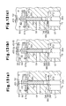
- a front housing member 12 is secured to the front end of a cylinder block 11.
- a rear housing member 13 is secured to the rear end of the cylinder block 11 with a valve plate 14, valve flap plates 15, 16, and a retainer plate 17 arranged in between.
- the cylinder block 11, the front housing member 12, and the rear housing member 13 form a housing of the compressor 10.
- the front housing member 12 and the cylinder block 11 define a control pressure chamber 121.
- the front housing member 12 and the cylinder block 11 rotatably support a rotary shaft 18 with radial bearings 19, 20.
- the rotary shaft 18 projects from the control pressure chamber 121 to the outside, and receives power from a vehicle engine E, which is an external power source, through an electromagnetic clutch (not shown).
- a rotary support 21 is fixed to the rotary shaft 18, and a swash plate 22 is supported on the rotary shaft 18.
- the swash plate 22 is permitted to incline with respect to and slide along the rotary shaft 18.
- a pair of guide holes 211 are formed in the rotary support 21, and a pair of guide pins 23 are formed on the swash plate 22.
- the guide pins 23 are slidably fitted in the guide holes 211.
- the engagement of the guide pins 23 with the guide holes 211 allows the swash plate 22 to be tiltable with respect to the rotary shaft 18 and rotatable together with the rotary shaft 18.
- the guide holes 211 slidably guide the guide pins 23, and the rotary shaft 18 slidably supports the swash plate 22. These actions permit the swash plate 22 to be inclined.
- the rotary support 21 determines the maximum inclination of the swash plate 22.
- the swash plate 22 is at the maximum inclination position.
- the swash plate 22 is at the minimum inclination position.
- the minimum inclination angle of the swash plate 22 is slightly greater than zero degrees.
- Cylinder bores 111 extend through the cylinder block 11. Each cylinder bore 111 accommodates a piston 24. The rotation of the swash plate 22 is converted to reciprocation of the pistons 24 by means of shoes 25. Thus, each piston 24 reciprocates in the corresponding cylinder bore 111.
- a suction chamber 131 and a discharge chamber 132 are defined in the rear housing member 13.
- Suction ports 141 are formed in a valve plate 14 and a valve flap plate 16.
- Discharge ports 142 are formed in the valve plate 14 and a valve flap plate 15.
- Suction valve flaps 151 are formed on the valve flap plate 15, and discharge valve flaps 161 are formed on the valve flap plate 16.
- gaseous refrigerant in the corresponding cylinder bore 111 is discharged to the discharge chamber 132, which is a discharge pressure zone, through the corresponding discharge port 142 while flexing the discharge valve flap 161.
- the retainer plate 17 includes retainers 171, which correspond to the discharge valves 161. Each retainer 171 restricts the opening degree of the corresponding discharge valve flap 161.
- a suction passage 26 for guiding refrigerant into the suction chamber 131 and a discharge passage 27 for discharging refrigerant from the discharge chamber 132 are connected to each other by an external refrigerant circuit 28.
- a heat exchanger 29 for drawing heat from refrigerant, an expansion valve 30, and a heat exchanger 31 for transferring the ambient heat to refrigerant are located on the external refrigerant circuit 28.
- the expansion valve 30 is an automatic thermal expansion valve that controls the flow rate of refrigerant in accordance with fluctuations of gas temperature at the outlet of the heat exchanger 31.
- a constriction 281 is provided in a part of the external refrigerant circuit (hereinafter referred to as circuit sections 28A, 28B) that is downstream of the discharge passage 27 and upstream of the heat exchanger 29.
- the circuit section 28A is located upstream of the constriction 281
- the circuit section 28B is located downstream of the constriction 281.
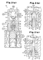
- An electromagnetic displacement control valve 32 is installed in the rear housing member 13.
- the displacement control valve 32 includes a solenoid 41.
- a fixed iron core 42 of the solenoid 41 attracts a movable iron core 44 based on excitation by current supplied to a coil 43.
- the solenoid 41 is subjected to current supply control (duty ratio control in this embodiment) executed by a control computer C (see Fig. 1 ).
- a transmission rod 45 is fixed to the movable iron core 44.
- a valve housing 33 which forms the displacement control valve 32, has a valve hole forming wall 34 and a valve seat 35.
- a first valve hole 36 is formed in the valve hole forming wall 34, and a second valve hole 37 is formed in the valve seat 35. That is, the valve housing 33 (specifically, the valve hole forming wall 34) functions as a first valve hole forming member.
- the valve seat 35 functions as a second valve hole forming member.
- the second valve hole 37 opens on the seating face 351.
- a chamber 46 is defined between the valve seat 35 and the fixed iron core 42.
- the transmission rod 45 extends through the chamber 46 and the second valve hole 37.
- a spring seat 55 is located in the chamber 46 and attached to the transmission rod 45.
- An urging spring 56 is located between the spring seat 55 and the valve seat 35.
- the transmission rod 45 is urged by the force of the urging spring 56 in a direction moving the movable iron core 44 away from the fixed iron core 42.
- the chamber 46 communicates with the suction chamber 131 through
- a shared chamber 38 is defined between the valve hole forming wall 34 and the valve seat 35 (between the first valve hole 36 and the second valve hole 37).
- the shared chamber 38 is connected to the first valve hole 36 and the second valve hole 37.
- the shared chamber 38 communicates with the control pressure chamber 121 through a passage 58.
- a first valve body 39 is integrally formed with (fixed to) the transmission rod 45. That is, the first valve body 39 functions as a fixed valve body that is fixed to the transmission rod 45 functioning as a reciprocating body.
- the first valve body 39 includes a cylindrical portion 391 and a tapered portion 392. The diameter of the tapered portion 392 is reduced in a direction from the second valve hole 37 to the first valve hole 36.
- a second valve body 40 is accommodated in the shared chamber 38.
- the second valve body 40 functions as a sliding valve body that is slidably fitted around the transmission rod 45.
- the cylindrical portion 391 of the first valve body 39 is configured to enter and close the first valve hole 36, while the second valve body 40 is configured to contact a seating face 351 of the valve seat 35 and close the second valve hole 37.
- the second valve body 40 has a valve closing face 403 that contacts the seating face 351 to close the corresponding second valve hole 37.
- a compression spring 47 is located between an opposing face 341 of the valve hole forming wall 34 and the second valve body 40.
- the compression spring 47 urges the second valve body 40 toward a closing position at which the second valve body 40 closes the second valve hole 37 (a position where the second valve body 40 contacts the seating face 351 of the valve seat 35).
- a step 451 is formed on the transmission rod 45.
- the second valve body 40 selectively contacts the step 451. Specifically, the step 451 can contact the valve closing face 403 of the second valve body 40.
- the second valve body 40 is urged toward the step 451 by the force of the compression spring 47.
- a distance H1 (see Fig. 2(b) ) between the step 451 and a boundary 393 between the cylindrical portion 391 of the first valve body 39 and the tapered portion 392 is greater than a distance K1 (see Fig. 2(b) ) between an open end 361 of the first valve hole 36 and the seating face 351.
- the boundary 393 functions as a first initial contact portion, or a portion of the first valve body 39 that initially contacts the circumferential surface of the first valve hole 36 when the first valve body 39 switches the corresponding first valve hole 36 from the open state to the closed state.
- the open end 361 of the first valve hole 36 functions as a second initial contact portion, which is a portion of the circumferential surface of the first valve hole 36 that initially contacts the boundary 393 when the first valve hole 36 is switched from the open state to the closed state.
- pressure sensing chambers 48, 49 are defined in the displacement control valve 32 by a bellows 50.
- a stationary end of the bellows 50 is coupled to an end wall 51 forming the valve housing 33.
- a movable end of the bellows 50 is coupled to a movable body 52, which functions as a movable portion.
- An end face 452 of the transmission rod 45 always contacts the movable body 52.
- the pressure sensing chamber 48 communicates with the section 28A of the external refrigerant circuit 28, which is upstream of the constriction 281, through a passage 53A, while the pressure sensing chamber 49 communicates with the section 28B of the external refrigerant circuit 28, which is downstream of the constriction 281, through a passage 53B. That is, the interior of the pressure sensing chamber 48 is exposed to the pressure of the circuit section 28A, which is upstream of the constriction 281, while the interior of the pressure sensing chamber 49 is exposed to the pressure of the circuit section 28B, which is downstream of the constriction 281 and upstream of the heat exchanger 29.
- the pressure in the pressure sensing chamber 48 and the pressure in the pressure sensing chamber 49 oppose each other with the bellows 50 in between.
- the pressure sensing chambers 48, 49 and the bellows 50 form a pressure sensing member 54 that senses the pressure difference between the pressure of the circuit section 28A, which is upstream of the constriction 281, and the pressure of the circuit section 28B, which is downstream of the constriction 281 and upstream of the heat exchanger 29.
- the pressure of the circuit section 28A, which is upstream of the constriction 281 is higher than the pressure of the circuit section 28B, which is downstream of the constriction 281 and upstream of the heat exchanger 29.
- the control computer C shown in Fig. 1 executes the current supply control (duty ratio control) for the solenoid 41 of the displacement control valve 32.
- the control computer C supplies current to the solenoid 41.
- the control computer C stops supplying the current.
- the control computer C is connected to a compartment temperature setting device 60 and a compartment temperature detector 61.
- the control computer C controls current supplied to the solenoid 41 based on the difference between a target compartment temperature set by the compartment temperature setting device 60 and the temperature detected by the compartment temperature detector 61.
- Figs. 1 , 2(a), and 2(b) show a state in which the air-conditioner switch 59 is ON, and the current control (duty ratio control) is being executed based on the difference between a target temperature set by manipulating the compartment temperature setting device 60 and the temperature detected by the compartment temperature detector 61.
- the duty ratio is set to 100% in the control of current to the solenoid 41.
- the movable iron core 44 is closest to the fixed iron core 42.
- the step 451 of the transmission rod 45 contacts the second valve body 40, and the second valve body 40 is at an opening position separated from the seating face 351 of the valve seat 35.
- the second valve hole 37 Since the second valve hole 37 is open, refrigerant in the shared chamber 38 flows to the chamber 46 through the second valve hole 37. That is, refrigerant in the control pressure chamber 121 flows out to the suction chamber 131 (suction pressure zone) through the passage 58, the shared chamber 38, the second valve hole 37, the chamber 46, and the passage 57.
- the cylindrical portion 391 of the first valve body 39 is in the first valve hole 36 so that the first valve hole 36 is closed. Since the first valve hole 36 is closed, refrigerant in the pressure sensing chamber 49 does not flow into the shared chamber 38 through the first valve hole 36.
- refrigerant in the pressure sensing chamber 49 does not flow into the control pressure chamber 121 through the first valve hole 36, the shared chamber 38, and the passage 58. That is, in the state shown in Figs. 1 , 2(a), and 2(b) , the displacement control valve 32 does not allow refrigerant in the circuit section 28B (discharge pressure zone) to flow into the control pressure chamber 121, while allowing refrigerant in the control pressure chamber 121 to flow out to the suction chamber 131. Therefore, the pressure in the control pressure chamber 121 is reduced, and the inclination angle of the swash plate 22 is maximized. Accordingly, the variable displacement compressor 10 operates at the maximum displacement.
- Figs. 2(c) , 3(a), and 3(b) show a state in which the air-conditioner switch 59 is ON, and the current control (duty ratio control) is being executed based on the difference between a target temperature set by manipulating the compartment temperature setting device 60 and the temperature detected by the compartment temperature detector 61.
- the step 451 of the transmission rod 45 contacts the second valve body 40, and the second valve body 40 is at an opening position separated from the seating face 351 of the valve seat 35. Since the second valve hole 37 is open, refrigerant in the control pressure chamber 121 flows out to the suction chamber 131 (suction pressure zone) through the passage 58, the shared chamber 38, the second valve hole 37, the chamber 46, and the passage 57. On the other hand, the cylindrical portion 391 of the first valve body 39 is in the first valve hole 36 so that the first valve hole 36 is closed.
- the opening degree of the second valve hole 37 in the state of Fig. 2(c) is less than that in the state of Fig. 2(b) .
- an intermediate displacement operation is performed in which the inclination angle of the swash plate 22 is less than the maximum inclination angle.
- the duty ratio control is being executed at a duty ratio that is less than that of the state shown in Fig. 2(c) .
- the step 451 of the transmission rod 45 contacts the second valve body 40, and the cylindrical portion 391 of the first valve body 39 is in the first valve hole 36 (the boundary 393 is in the first valve hole 36).
- the second valve body 40 is in a position where it contacts the seating face 351 of the valve seat 35 (a position where the second valve body 40 closes the second valve hole 37). That is, the second valve hole 37 is closed by the second valve body 40.
- the duty ratio control is being executed at a duty ratio that is less than that of the state shown in Fig. 3(a) .
- the step 451 of the transmission rod 45 is separated from the second valve body 40, and the cylindrical portion 391 of the first valve body 39 is in the first valve hole 36 (the boundary 393 is in the first valve hole 36).
- the second valve body 40 is in a position where it contacts the seating face 351 of the valve seat 35 (a position where the second valve body 40 closes the second valve hole 37). That is, the second valve hole 37 is closed by the second valve body 40.
- the first valve body 39 is in a position where it closes the first valve hole 36
- the second valve body 40 is in a position where it closes the second valve hole 37.
- the electromagnetic force of the solenoid 41 is reduced from the state of Fig. 3(a) (a state in which the end face 452 of the transmission rod 45 is in a position W1)
- the end face 452 of the transmission rod 45 is moved from the position W1 toward the first valve hole 36
- the step 451 is separated from the second valve body 40.
- the electromagnetic force of the solenoid 41 is increased from the state of Fig.
- the displacement range [W1, W2] is a predetermined range of a double closing state of the transmission rod 45, in which the first valve body 39 closes the first valve hole 36, and the second valve body 40 closes the second valve hole 37.
- the transmission rod 45 which is a reciprocating body
- the double closing state occurs, in which the first valve body 39 closes the first valve hole 36, and the second valve body 40 closes the second valve hole 37. This state is obtained because the distance H1 between the step 451 and the boundary 393 is greater than the distance K1 between the open end 361 and the seating face 351.
- the distance H1 between the displacement transmission portion (the step 451) and the first initial contact portion (the boundary 393 of the first valve body 39) is different from the distance K1 between the second initial contact portion (the open end 361 of the first valve hole 36) and the seating face 351.
- the step 451 of the transmission rod 45 is separated from the second valve body 40, and the second valve body 40 is in the position where it contacts the seating face 351 of the valve seat 35 (the position where it closes the second valve hole 37). Since the second valve hole 37 is closed, refrigerant in the shared chamber 38 does not flow out to the chamber 46 through the second valve hole 37. That is, refrigerant in the control pressure chamber 121 does not flow out to the suction chamber 131 (suction pressure zone) through the passage 58, the shared chamber 38, the second valve hole 37, the chamber 46, and the passage 57. On the other hand, the cylindrical portion 391 of the first valve body 39 is out of the first valve hole 36 so that the first valve hole 36 is open.
- the displacement control valve 32 allows refrigerant in the circuit section 28B (discharge pressure zone) to flow into the control pressure chamber 121, while preventing refrigerant in the control pressure chamber 121 from flowing out to the suction chamber 131. Therefore, the pressure in the control pressure chamber 121 is high, and the inclination angle of the swash plate 22 is minimized. Accordingly, the variable displacement compressor 10 operates at the minimum displacement.
- the opening degree of the first valve hole 36 is determined by the balance of the electromagnetic force produced by the solenoid 41, the force of the urging spring 56, and the force of the pressure sensing member 54.
- the opening degree of the second valve hole 37 is determined by the balance of the electromagnetic force produced by the solenoid 41, the force of the urging spring 56, the force of the compression spring 47, and the force of the pressure sensing member 54.
- the first valve hole 36 forms a supply passage for supplying refrigerant of the circuit section 28B (discharge pressure zone) to the control pressure chamber 121.
- the second valve hole 37 forms a discharge passage for discharging refrigerant of the control pressure chamber 121 to the suction chamber 131 (suction pressure zone).
- the displacement control valve 32 is a control valve of a valve opening degree changing type, which changes the electromagnetic force (duty ratio), thereby continuously varying the flow passage areas of the first valve hole 36 and the second valve hole 37.
- the air-conditioner switch 59, the compartment temperature setting device 60, the compartment temperature detector 61, and the control computer C form an electromagnetic force changing unit for changing the electromagnetic force in the displacement control valve 32.
- carbon dioxide is used as refrigerant.
- the first embodiment provides the following advantages.
- a first chamber 63 and a second chamber 64 are defined by a separation member 62 between the valve hole forming wall 34 and the valve seat 35.
- the first chamber 63 is connected to the first valve hole 36
- the second chamber 64 is connected to the second valve hole 37.
- the first chamber 63 communicates with the control pressure chamber 121 through a passage 65
- the second chamber 64 communicates with the control pressure chamber 121 through a passage 66.
- the compression spring 47 is located between the separation member 62 and the second valve body 40 and urges the second valve body 40 in a direction from the first valve hole 36 to the second valve hole 37.
- the distance H1 between the step 451 and the boundary 393 is greater than the distance K1 between the open end 361 and the seating face 351 of the valve seat 35.
- the second embodiment has the same advantages as the advantages (1-1) to (1-6) of the first embodiment.
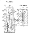
- FIG. 5(a) to 6(c) A third embodiment will now be described with reference to Figs. 5(a) to 6(c) .
- Like or the same reference numerals are given to those components that are like or the same as the corresponding components of the first embodiment shown in Figs. 1 to 3(c) .
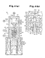
- a first valve body 67 is accommodated in the shared chamber 38 between a valve seat 69 and a valve hole forming plate 70.
- the first valve body 67 is slidably fitted around a sliding portion 453 formed on the transmission rod 45.
- the first valve body 67 has a valve closing face 673 that contacts the seating face 691 of the valve seat 69 to close the corresponding first valve hole 36.
- a second valve body 68 is integrally formed with (fixed to) the transmission rod 45.
- the second valve body 68 includes a cylindrical portion 681 and a tapered portion 682. The diameter of the tapered portion 682 is reduced in a direction from the first valve hole 36 to the second valve hole 37.
- the cylindrical portion 681 of the second valve body 68 is configured to enter and close the second valve hole 37, while the first valve body 67 is configured to contact a seating face 691 of the valve seat 69 and close the first valve hole 36.
- a compression spring 71 is located between the valve hole forming plate 70 and the first valve body 67.
- the compression spring 71 urges the first valve body 67 toward a closing position at which the first valve body 67 closes the first valve hole 36 (a position where the first valve body 67 contacts the seating face 691 of the valve seat 69).
- An auxiliary rod 72 is attached to the movable body 52 of the pressure sensing member 54 at a coupling face 722.
- An end face 721 of the auxiliary rod 72 always contacts an end face 454 of the transmission rod 45.
- the diameter of the end face 721 of the auxiliary rod 72, which forms a reciprocating body with the transmission rod 45, is greater than the diameter of the end face 454 of the sliding portion 453.
- the end face 721 of the auxiliary rod 72 selectively contacts the first valve body 67.
- the valve body 67 is urged toward the end face 721 by the force of the compression spring 71.
- a distance H2 (see Fig. 5(b) ) between the end face 721 and a boundary 683 between the cylindrical portion 681 of the second valve body 68 and the tapered portion 682 is greater than a distance K2 (see Fig. 5(b) ) between an open end 371 of the second valve hole 37 and the seating face 691.
- the duty ratio is set to 100% in the control of current to the solenoid 41.
- the end face 721 of the auxiliary rod 72 is farthest from the first valve hole 36, and the second valve body 68 is located at an opening position away from the second valve hole 37. Since the second valve hole 37 is open, refrigerant in the control pressure chamber 121 flows out to the suction chamber 131 (suction pressure zone) through the passage 58, the shared chamber 38, the second valve hole 37, the chamber 46, and the passage 57.
- the first valve body 67 contacts the seating face 691 of the valve seat 69 so that the first valve hole 36 is closed.
- the displacement control valve 32 Since the first valve hole 36 is closed, refrigerant in the pressure sensing chamber 49 does not flow into the control pressure chamber 121 through the first valve hole 36, the shared chamber 38, and the passage 58. That is, in the state shown in Figs. 5(a) and 5(b) , the displacement control valve 32 does not allow refrigerant in the circuit section 28A (discharge pressure zone) to flow into the control pressure chamber 121.
- the displacement control valve 32 also allows refrigerant in the control pressure chamber 121 to flow out to the suction chamber 131. Therefore, the pressure in the control pressure chamber 121 is reduced, and the inclination angle of the swash plate 22 is maximized. Accordingly, the variable displacement compressor 10 operates at the maximum displacement.
- the duty ratio control is being executed at a relatively high duty ratio.
- the tapered portion 682 of the second valve body 68 is in the second valve hole 37, while the boundary 683 is not in the second valve hole 37. That is, the second valve body 68 is at the opening position, where it opens the second valve hole 37. Since the second valve hole 37 is open, refrigerant in the control pressure chamber 121 flows out to the suction chamber 131 (suction pressure zone) through the passage 58, the shared chamber 38, the second valve hole 37, the chamber 46, and the passage 57.
- the first valve body 67 contacts the seating face 691 so that the first valve hole 36 is closed.
- the opening degree of the second valve hole 37 in the state of Fig. 5(c) is less than that in the state of Fig. 5(b) .
- an intermediate displacement operation is performed in which the inclination angle of the swash plate 22 is less than the maximum inclination angle.
- the duty ratio control is being executed at a duty ratio that is less than that of the state shown in Fig. 5(c) .
- the end face 721 of the auxiliary rod 72 is separated from the first valve body 67, and the cylindrical portion 681 of the second valve body 68 is in the second valve hole 37 (the boundary 683 is in the second valve hole 37).
- the first valve body 67 is in a position where it contacts the seating face 691 of the valve seat 69 (a position where the first valve body 67 closes the first valve hole 36). That is, the first valve hole 36 is closed by the first valve body 67.
- the duty ratio control is being executed at a duty ratio that is less than that of the state shown in Fig. 6(a) .
- the end face 721 of the auxiliary rod 72 contacts the first valve body 67, and the cylindrical portion 681 of the second valve body 68 is in the second valve hole 37 (the boundary 683 is in the first valve hole 36).
- the second valve hole 37 is closed by the second valve body 68.
- the first valve body 67 is in a position where it contacts the seating face 691 of the valve seat 69 (a position where the first valve body 67 closes the first valve hole 36). That is, the first valve hole 36 is closed by the first valve body 67.
- the first valve body 67 is in a position where it contacts the seating face 691 of the valve seat 69 (closing position for closing the first valve hole 36), and the cylindrical portion 681 of the second valve body 68 is in the second valve hole 37 (the boundary 683 is in the second valve hole 37).
- the displacement range [W1, W2] is a predetermined range of a double closing state of the transmission rod 45, in which the first valve body 67 closes the first valve hole 36, and the second valve body 68 closes the second valve hole 37.
- the transmission rod 45 which is a reciprocating body
- the double closing state occurs, in which the first valve body 67 closes the first valve hole 36, and the second valve body 68 closes the second valve hole 37. This state is obtained because the distance H2 between the end face 721 and the boundary 683 is greater than the distance K2 between the seating face 691 and the open end 371.
- the state shown in Fig. 6(c) is obtained (including a case where the duty ratio is zero).
- the end face 721 of the auxiliary rod 72 contacts the first valve body 67, and the first valve body 67 is separated from the seating face 691. That is, the first valve hole 36 is open. Since the first valve hole 36 is open, refrigerant in the pressure sensing chamber 49 flows into the control pressure chamber 121 through the first valve hole 36, the shared chamber 38, and the passage 58.
- the cylindrical portion 681 of the second valve body 68 is in the second valve hole 37 so that the second valve hole 37 is closed.
- the displacement control valve 32 allows refrigerant in the circuit section 28B (discharge pressure zone) to flow into the control pressure chamber 121, while preventing refrigerant in the control pressure chamber 121 from flowing out to the suction chamber 131. Therefore, the pressure in the control pressure chamber 121 is high, and the inclination angle of the swash plate 22 is minimized. Accordingly, the variable displacement compressor 10 operates at the minimum displacement.
- the transmission rod 45 is out of the predetermined displacement range [W1, W2]
- the first valve body 67 opens the first valve hole 36
- the second valve body 68 closes the second valve hole 37.
- the transmission rod 45 is out of the predetermined displacement range [W1, W2]
- the first valve body 67 closes the first valve hole 36
- the second valve body 68 opens the second valve hole 37. That is, when the transmission rod 45 is out of the predetermined displacement range [W1, W2], one of the state in which the first valve body 67 closes the first valve hole 36, and the state in which the second valve body 68 closes the second valve hole 37 occurs.
- the third embodiment has the same advantages as the advantages (1-1) and (1-5) of the first embodiment. Further, the third embodiment provides the following advantages.
- FIG. 7 A fourth embodiment will now be described with reference to Fig. 7 .
- Like or the same reference numerals are given to those components that are like or the same as the corresponding components of the second embodiment shown in Figs. 4(a) and 4(b) and the third embodiment shown in Figs. 5(a) to 6(c) .
- a first chamber 74 and a second chamber 75 are defined by a separation member 73 between the valve seat 69 and the valve hole forming plate 70.
- the first chamber 74 is connected to the first valve hole 36
- the second chamber 75 is connected to the second valve hole 37.
- the first chamber 74 communicates with the control pressure chamber 121 through a passage 65
- the second chamber 75 communicates with the control pressure chamber 121 through a passage 66.
- the compression spring 76 is located between the separation member 73 and the first valve body 67 and urges the first valve body 67 in a direction from the second valve hole 37 to the first valve hole 36.
- the distance H2 between the end face 721 and the boundary 683 is greater than the distance K2 between the seating face 691 and the open end 371.
- the fourth embodiment thus provides the same advantages as the third embodiment.
- FIG. 8(a) and 8(b) A fifth embodiment will now be described with reference to Figs. 8(a) and 8(b) .
- Like or the same reference numerals are given to those components that are like or the same as the corresponding components of the first embodiment shown in Figs. 1 to 3(c) and the third embodiment shown in Figs. 5(a) to 6(c) .
- the first valve body 39 of the first embodiment and the second valve body 68 of the third embodiment are used together. That is, the first valve body 39 and the second valve body 68 are both integrally formed with (fixed to) the transmission rod 45. That is, both of the first valve body 39 and the second valve body 68 are fixed valve bodies that are fixed to the transmission rod 45.
- a distance H3 between the boundary 393 of the first valve body 39 and the boundary 683 of the second valve body 68 is greater than a distance K3 between the open end 361 of the first valve hole 36 and the open end 371 of the second valve hole 37.
- a double closing state occurs, in which the first valve body 39 is in the first valve hole 36 and closes the first valve hole 36, and the second valve body 68 is in the second valve hole 37 and closes the second valve hole 37.
- the first valve body 39 enters the first valve hole 36 to close the first valve hole 36.
- the valve bodies 39, 68 fixed to the transmission rod 45 are in positions closing the valve holes 36, 37.
- the fifth embodiment has the same advantages as the advantages (1-1), (1-3) to (1-6) of the first embodiment, and the advantages (3-2) to (3-4) of the third embodiment.
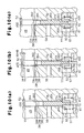
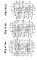
- FIG. 9(a), 9(b), 9(c) , 10(b), and 10(c) Like or the same reference numerals are given to those components that are like or the same as the corresponding components of the first embodiment shown in Figs. 1 to 3(c) .
- a displacement control valve 32A includes a solenoid 41A.
- a fixed iron core 42A of the solenoid 41 attracts a movable iron core 44A based on excitation by current supplied to a coil 43A.
- An urging spring 80 is located between the fixed iron core 42A and the movable iron core 44A. The urging spring 80 urges the movable iron core 44A in a direction away from the fixed iron core 42A.
- a transmission rod 45A is fixed to the movable iron core 44A.
- the pressure sensing chamber 48 communicates with a section 28B of the external refrigerant circuit 28, which is downstream of the constriction 281, through a passage 53B, while the pressure sensing chamber 49 communicates with a section 28A of the external refrigerant circuit 28, which is upstream of the constriction 281, through a passage 53A. That is, the pressure sensing chamber 48 is exposed to the pressure in the circuit section 28B, and the pressure sensing chamber 49 is exposed the pressure of the circuit section 28A.
- the pressure in the pressure sensing chamber 48 and the pressure in the pressure sensing chamber 49 oppose each other with the bellows 50 in between.
- the pressure sensing chambers 49, 48 and the bellows 50 form a pressure sensing member 54A that senses the pressure difference between the pressure of the circuit section 28A, which is upstream of the constriction 281, and the pressure of the circuit section 28B, which is downstream of the constriction 281 and upstream of the heat exchanger 29.
- a valve housing 33A which forms the displacement control valve 32A, has a valve hole forming portion 77.
- a first valve hole 36A, a shared passage 78, and a second valve hole 37A are formed in the valve hole forming portion 77.
- the first valve hole 36A and the second valve hole 37A communicate with each other through the shared passage 78.
- the shared passage 78 communicates with the control pressure chamber 121 through the passage 58.
- An accommodation chamber 79 is defined between the valve hole forming portion 77 and the movable iron core 44A.
- the accommodation chamber 79 communicates with the suction chamber 131 through a passage 57.
- the transmission rod 45A extends through the accommodation chamber 79, the second valve hole 37A, the shared passage 78, and the first valve hole 36A, and projects into the pressure sensing chamber 49.
- the transmission rod 45A is attached to the movable body 52 at an end face 455.
- the first valve body 39A includes a cylindrical portion 394 and a tapered portion 395.
- the diameter of the tapered portion 395 is increased in a direction from the second valve hole 37A to the first valve hole 36A.
- a second valve body 40A is accommodated in the accommodation chamber 79.
- the second valve body 40A is slidably fitted around the transmission rod 45A.
- the cylindrical portion 394 of the first valve body 39A is configured to enter and close the first valve hole 36A, while the second valve body 40A is configured to contact a seating face 771 of the valve hole forming portion 77 and close the second valve hole 37A.
- a compression spring 82 is located between a spring seat 81 and the second valve body 40A.
- the compression spring 82 urges the second valve body 40A toward a closing position at which the second valve body 40A closes the second valve hole 37A (a position where the second valve body 40A contacts the seating face 771).
- a step 456 is formed on the transmission rod 45A. The second valve body 40A selectively contacts the step 456. The second valve body 40A is urged toward the step 456 by the force of the compression spring 82.
- a distance H4 (see Fig. 9(b) ) between the step 456 and a boundary 396 between the cylindrical portion 394 of the first valve body 39A and the boundary 396 is less than a distance K4 (see Fig. 9(b) ) between an open end 362 of the first valve hole 36A and the seating face 771.
- the duty ratio is set to 100% in the control of current to the solenoid 41A.
- the movable iron core 44A is closest to the fixed iron core 42A.
- the step 456 of the transmission rod 45A contacts the second valve body 40A, and the second valve body 40A is at an opening position separated from the seating face 771. Since the second valve hole 37A is open, refrigerant in the control pressure chamber 121 flows out to the suction chamber 131 (suction pressure zone) through the passage 58, the shared passage 78, the second valve hole 37A, the accommodation chamber 79, and the passage 57.
- the cylindrical portion 394 of the first valve body 39A is in the first valve hole 36A so that the first valve hole 36A is closed. Since the first valve hole 36A is closed, refrigerant in the pressure sensing chamber 49 does not flow into the control pressure chamber 121 through the first valve hole 36A, the shared passage 78, and the passage 58. Therefore, the pressure in the control pressure chamber 121 is reduced, and the inclination angle of the swash plate 22 is maximized. Accordingly, the variable displacement compressor 10 (see Fig. 1 ) operates at the maximum displacement.
- the step 456 of the transmission rod 45A contacts the second valve body 40A, and the second valve body 40A is at an opening position separated from the seating face 771. Since the second valve hole 37A is open, refrigerant in the control pressure chamber 121 flows out to the suction chamber 131 (suction pressure zone) through the passage 58, the shared passage 78, the second valve hole 37A, the accommodation chamber 79, and the passage 57. On the other hand, the cylindrical portion 394 of the first valve body 39A is in the first valve hole 36A so that the first valve hole 36A is closed. Since the first valve hole 36A is closed, refrigerant in the pressure sensing chamber 49 does not flow into the control pressure chamber 121 through the first valve hole 36A, the shared passage 78, and the passage 58.
- the opening degree of the second valve hole 37A in the state of Fig. 9(c) is less than that in the state of Fig. 9(b) .
- an intermediate displacement operation is performed in which the inclination angle of the swash plate 22 is less than the maximum inclination angle.
- the duty ratio control is being executed at a duty ratio that is less than that of the state shown in Fig. 9(c) .
- the step 456 of the transmission rod 45A contacts the second valve body 40A, and the cylindrical portion 394 of the first valve body 39A is in the first valve hole 36A (the boundary 396 is in the first valve hole 36A).
- the second valve body 40A is in a position where it contacts the seating face 771 (a position where the second valve body 40A closes the second valve hole 37A). That is, the second valve hole 37A is closed by the second valve body 40A.
- the duty ratio control is being executed at a duty ratio that is less than that of the state shown in Fig. 10(a) .
- the step 456 of the transmission rod 45A is separated from the second valve body 40A, and the cylindrical portion 394 of the first valve body 39A is in the first valve hole 36A (the boundary 396 is in the first valve hole 36A).
- the second valve body 40A is in a position where it contacts the seating face 771 (a position where the second valve body 40A closes the second valve hole 37A). That is, the second valve hole 37A is closed by the second valve body 40A.
- the cylindrical portion 394 of the first valve body 39A is in the first valve hole 36A, and the second valve body 40A is in a position where it closes the second valve hole 37A.
- the electromagnetic force of the solenoid 41A is reduced from the state of Fig. 10(a) (a state in which the end face 455 of the transmission rod 45A is in a position W3), the end face 455 of the transmission rod 45 is moved away from the first valve hole 36A, so that the step 456 is separated from the second valve body 40A.
- the electromagnetic force of the solenoid 41A is increased from the state of Fig.
- the displacement range [W3, W4] is a predetermined range of a double closing state of the transmission rod 45A, in which the first valve body 39A closes the first valve hole 36A, and the second valve body 40A closes the second valve hole 37A.
- the transmission rod 45A which is a reciprocating body
- the double closing state occurs, in which the first valve body 39A closes the first valve hole 36A, and the second valve body 40A closes the second valve hole 37A.
- This state is obtained because the distance H4 between the step 456 and the boundary 396 is less than the distance K4 between the open end 362 of the first valve hole 36A and the seating face 771.
- the step 456 of the transmission rod 45A is separated from the second valve body 40A, and the second valve body 40A is in the position where it contacts the seating face 771 (the closing position for closing the second valve hole 37A). Since the second valve hole 37A is closed, refrigerant in the control pressure chamber 121 does not flow out to the suction chamber 131 (suction pressure zone) through the passage 58, the shared passage 78, the second valve hole 37A, the accommodation chamber 79, and the passage 57. On the other hand, the cylindrical portion 394 of the first valve body 39A is out of the first valve hole 36A so that the first valve hole 36A is open.
- variable displacement compressor 10 operates at the minimum displacement.
- the opening degree of the first valve hole 36A is determined by the balance of the electromagnetic force produced by the solenoid 41A, the force of the urging spring 80, and the force of the pressure sensing member 54A.
- the opening degree of the second valve hole 37A is determined by the balance of the electromagnetic force produced by the solenoid 41A, the force of the urging spring 80, the force of the compression spring 82, and the force of the pressure sensing member 54A.
- the first valve hole 36A forms a supply passage for supplying refrigerant of the circuit section 28A (discharge pressure zone) to the control pressure chamber 121.
- the second valve hole 37A forms a discharge passage for discharging refrigerant of the control pressure chamber 121 to the suction chamber 131 (suction pressure zone).
- the displacement control valve 32A is a control valve of a valve opening degree changing type, which changes the electromagnetic force (duty ratio), thereby continuously varying the flow passage areas of the first valve hole 36A and the second valve hole 37A.
- the sixth embodiment has the same advantages as the advantages (1-1) and (1-5) of the first embodiment. Further, the sixth embodiment provides the following advantages.
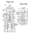
- FIG. 11(a) and 11(b) A seventh embodiment will now be described with reference to Figs. 11(a) and 11(b) .
- Like or the same reference numerals are given to those components that are like or the same as the corresponding components of the sixth embodiment shown in Figs. 9 and 10 .
- the first valve hole 36A and the second valve hole 37A are separated from each other by a separation portion 83, which is a separation member, formed on the circumference of the transmission rod 45A.
- the first valve hole 36A communicates with the control pressure chamber 121 through a passage 65
- the second valve hole 37A communicates with the control pressure chamber 121 through a passage 66.
- the distance H4 between the step 456 and the boundary 396 is less than the distance K4 between the open end 362 of the first valve hole 36A and the seating face 771.
- the seventh embodiment thus provides the same advantages as the sixth embodiment.
- a first valve body 67A is accommodated in the pressure sensing chamber 49.
- the first valve body 67A is slidably fitted around the transmission rod 45A.
- a step 457 is formed on the transmission rod 45A. The first valve body 67A selectively contacts the step 457.
- a second valve body 68A is integrally formed with (fixed to) the transmission rod 45A.
- the second valve body 68A includes a cylindrical portion 684 and a tapered portion 685.
- the diameter of the tapered portion 685 is increased in a direction from the first valve hole 36A to the second valve hole 37A.
- the cylindrical portion 684 of the second valve body 68A is configured to enter and close the second valve hole 37A, while the first valve body 67A is configured to contact a seating face 772 of the valve hole forming portion 77 and close the first valve hole 36A.
- a compression spring 84 is located between the end wall 51 and the first valve body 67A.
- the compression spring 84 urges the first valve body 67A toward a closing position at which the first valve body 67A closes the first valve hole 36A (a position where the first valve body 67A contacts the seating face 772).
- the first valve body 67A is urged toward the step 457 by the force of the compression spring 84.
- a distance H5 (see Fig. 12(b) ) between the step 457 and a boundary 686 between the cylindrical portion 684 of the second valve body 68A and the tapered portion 685 is less than a distance K5 (see Fig. 12(b) ) between an open end 372 of the second valve hole 37A and the seating face 772.
- the duty ratio is set to 100% in the control of current to the solenoid 41A.
- the step 457 of the transmission rod 45A is separated from the first valve body 67A, and the first valve body 67A contacts the seating face 772. That is, the first valve hole 36A is closed.
- the cylindrical portion 684 of the second valve body 68A is out of the second valve hole 37A so that the second valve hole 37A is open. Therefore, the pressure in the control pressure chamber 121 is reduced, and the inclination angle of the swash plate 22 (see Fig. 1 ) is maximized. Accordingly, the variable displacement compressor 10 (see Fig. 1 ) operates at the maximum displacement.
- the duty ratio control is being executed at a relatively high duty ratio.
- the step 457 of the transmission rod 45A is separated from the first valve body 67A, and the first valve hole 36A is closed by the first valve body 67A.
- the cylindrical portion 684 of the second valve body 68A is out of the second valve hole 37A so that the second valve hole 37A is open.
- the opening degree of the second valve hole 37A in the state of Fig. 12(c) is less than that in the state of Fig. 12(b) .
- an intermediate displacement operation is performed in which the inclination angle of the swash plate 22 is less than the maximum inclination angle.
- the duty ratio control is being executed at a duty ratio that is less than that of the state shown in Fig. 12(c) .
- the step 457 of the transmission rod 45A is separated from the first valve body 67A, and the cylindrical portion 684 of the second valve body 68A is in the second valve hole 37A (the boundary 686 is in the second valve hole 37A).
- the first valve body 67A is in a position where it contacts the seating face 772 (a closing position for the first valve hole 36A). That is, the first valve hole 36A is closed by the first valve body 67A.
- the duty ratio control is being executed at a duty ratio that is less than that of the state shown in Fig. 13(a) .
- the step 457 of the transmission rod 45A contacts the first valve body 67A, and the cylindrical portion 684 of the second valve body 68A is in the second valve hole 37A (the boundary 686 is in the second valve hole 37A).
- the first valve body 67A is in a position where it contacts the seating face 772 (a closing position for closing the first valve hole 36A). That is, the first valve hole 36A is closed by the first valve body 67A.
- the cylindrical portion 684 of the second valve body 68A is in the second valve hole 37A, and the first valve body 67A is in a closing position for closing the first valve hole 36A.
- the electromagnetic force of the solenoid 41A is reduced from the state of Fig. 13(a) (a state in which the end face 455 of the transmission rod 45A is in a position W3), the end face 455 of the transmission rod 45A is moved away from the first valve hole 36A, so that the step 457 approaches the first valve body 67A.
- the electromagnetic force of the solenoid 41A is increased from the state of Fig.
- the displacement range [W3, W4] is a predetermined range of a double closing state of the transmission rod 45A, in which the first valve body 67A closes the first valve hole 36A, and the second valve body 68A closes the second valve hole 37A.
- the transmission rod 45A which is a reciprocating body
- the double closing state occurs, in which the first valve body 67A closes the first valve hole 36A, and the second valve body 68A closes the second valve hole 37A.
- This state is obtained because the distance H5 between the step 457 and the boundary 686 is less than the distance K5 between the seating face 772 and the open end 372 of the second valve hole 37A.
- the state shown in Fig. 13(c) is obtained (including a case where the duty ratio is zero).
- the step 457 of the transmission rod 45A contacts the first valve body 67A, and the first valve body 67A is in the position where it is separated from the seating face 772 (the position opening the first valve hole 36A).
- the cylindrical portion 684 of the second valve body 68A is in the second valve hole 37A so that the second valve hole 37A is closed. Therefore, the pressure in the control pressure chamber 121 is high, and the inclination angle of the swash plate 22 is minimized. Accordingly, the variable displacement compressor 10 operates at the minimum displacement.
- the opening degree of the first valve hole 36A is determined by the balance of the electromagnetic force produced by the solenoid 41A, the force of the urging spring 80, the force of the compression spring 84, and the force of the pressure sensing member 54A.
- the opening degree of the second valve hole 37A is determined by the balance of the electromagnetic force produced by the solenoid 41A, the force of the urging spring 80, and the force of the pressure sensing member 54A.
- the eighth embodiment has the same advantages as the advantages (1-1) and (1-5) of the first embodiment. Further, the eighth embodiment provides the following advantages.
- FIG. 14 A ninth embodiment will now be described with reference to Fig. 14 .
- Like or the same reference numerals are given to those components that are like or the same as the corresponding components of the eighth embodiment shown in Figs. 12 and 13 .
- the first valve hole 36A and the second valve hole 37A are separated from each other by a separation portion 83 formed on the circumference of the transmission rod 45A.
- the first valve hole 36A communicates with the control pressure chamber 121 through a passage 65
- the second valve hole 37A communicates with the control pressure chamber 121 through a passage 66.
- the distance H5 between the step 457 and the boundary 686 is less than the distance K5 between the seating face 772 and the open end 372 of the second valve hole 37A.
- the ninth embodiment thus provides the same advantages as the eighth embodiment.
- FIG. 15(a) and 15(b) A tenth embodiment will now be described with reference to Figs. 15(a) and 15(b) .
- Like or the same reference numerals are given to those components that are like or the same as the corresponding components of the sixth embodiment shown in Figs. 9 and 10 and the eighth embodiment shown in Figs. 12 and 13 .
- first valve body 39A of the sixth embodiment and the second valve body 68A of the eighth embodiment are used together. That is, the first valve body 39A and the second valve body 68A are both integrally formed with (fixed to) the transmission rod 45A.
- a distance H6 between the boundary 396 of the first valve body 39A and the boundary 686 of the second valve body 68A is less than a distance K6 between the open end 362 of the first valve hole 36A and the open end 372 of the second valve hole 37A.
- the tenth embodiment has the same advantages as the advantages (1-1) and (1-5) of the first embodiment, advantages (6-1) to (6-4) of the sixth embodiment, and the advantages (8-1) to (8-4) of the eighth embodiment.
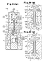
- a pair of valve seats 85, 35 are formed in a valve housing 33 that forms part of a displacement control valve 32.
- a first valve hole 36 is formed in the valve seat 85, and a second valve hole 37 is formed in the valve seat 35.
- the transmission rod 45 extends through the chamber 46 and the second valve hole 37.
- a shared chamber 38 is defined between the valve seat 85 and the valve seat 35 (between the first valve hole 36 and the second valve hole 37).
- a first valve body 67 and a second valve body 40 are accommodated in the shared chamber 38.
- the first valve body 67 and the second valve body 40 are slidably fitted around the transmission rod 45.
- the first valve body 67 is configured to contact the valve seat 85 and close the first valve hole 36, while the second valve body 40 is configured to contact the valve seat 35 and close the second valve hole 37.
- An auxiliary rod 87 is attached to the movable body 52 of the pressure sensing member 54 at a coupling face 872.
- An end face 871 of the auxiliary rod 87 always contacts an end face 452 of the transmission rod 45.
- the diameter of the end face 871 of the auxiliary rod 87, which forms a reciprocating body with the transmission rod 45, is greater than the diameter of the end face 452 of the transmission rod 45.
- the end face 871 which functions as a first displacement transmission portion, selectively contacts the first valve body 67.
- the end face 871 contacts the second valve body 40 to transmit displacement of the transmission rod 45, thereby moving the second valve body 40, which functions as a sliding valve body, from the closing position to the opening position.
- a compression spring 99 is located between the first valve body 67 and the valve seat 35, and a compression spring 86 is located between the first valve body 67 and the second valve body 40.
- the compression spring 99 urges the first valve body 67 toward a closing position at which the first valve body 67 closes the first valve hole 36 (a position where the first valve body 67 contacts the valve seat 85).
- the compression spring 86 urges the first valve body 67 toward a closing position at which the first valve body 67 closes the first valve hole 36 (a position where the first valve body 67 contacts the valve seat 85).
- the compression spring 86 also urges the second valve body 40 toward a closing position at which the second valve body 40 closes the second valve hole 37 (a position where the second valve body 67 contacts the valve seat 35).
- the first valve body 67 is urged toward the end face 871 by the force of the compression spring 99.
- the second valve body 40 is urged toward the step 451, which functions as a second displacement transmission portion, by the force of the compression spring 86.
- the compression spring 99 functions as a first urging member that urges the first valve body 67 toward a position at which the first valve body 67 contacts the end face 871.
- the compression spring 86 functions as a second urging member that urges the second valve body 40 toward a position at which the second valve body 40 contacts the step 451.
- the displacement control valve 32 has a seating face 851 in which the first valve hole 36 opens and a seating face 351 in which the second valve hole 37 opens.
- a distance K7 between the seating face 851 of the valve seat 85 and the seating face 351 of the valve seat 35 is less than a distance H7 (shown in Fig. 16(b) ) between the end face 871 and the step 451. That is, to ensure that the predetermined displacement range [W1, W2] be created, the distance K7 between the seating faces 851, 351 is different from the distance H7 between the first displacement transmission portion (end face 871) and the second displacement transmission portion (the step 451).
- the duty ratio is set to 100% in the control of current to the solenoid 41.
- the end face 871 is separated from the first valve body 67, and the step 451 contacts the second valve body 40. That is, the first valve hole 36 is open, and the second valve hole 37 is closed. Therefore, the pressure in the control pressure chamber 121 is reduced, and the inclination angle of the swash plate 22 (see Fig. 1 ) is maximized. Accordingly, the variable displacement compressor 10 (see Fig. 1 ) operates at the maximum displacement.
- the duty ratio control is being executed at a relatively high duty ratio.
- the end face 871 is separated from the first valve body 67, and the first valve body 67 contacts the seating face 851.
- the step 451 contacts the second valve body 40, and the second valve body 40 is separated from the seating face 351. That is, the first valve hole 36 is closed, and the second valve hole 37 is open.
- the opening degree of the second valve hole 37 in the state of Fig. 16(c) is less than that in the state of Fig. 16(b) .
- an intermediate displacement operation is performed in which the inclination angle of the swash plate 22 is less than the maximum inclination angle.
- the duty ratio control is being executed at a duty ratio that is less than that of the state shown in Fig. 16(c) .
- the end face 871 is separated from the first valve body 67, and the step 451 contacts the second valve body 40.
- the first valve body 67 closes the first valve hole 36
- the second valve body 40 closes the second valve hole 37.
- the duty ratio control is being executed at a duty ratio that is less than that of the state shown in Fig. 17(a) .
- the end face 871 contacts the first valve body 67, and the step 451 is separated from the second valve body 40.
- the first valve body 67 closes the first valve hole 36, and the second valve body 40 closes the second valve hole 37.
- the displacement range [W5, W6] is a predetermined range of a double closing state of the transmission rod 45, in which the first valve body 67 closes the first valve hole 36, and the second valve body 40 closes the second valve hole 37.
- the transmission rod 45 which is a reciprocating body
- the double closing state occurs, in which the first valve body 67 closes the first valve hole 36, and the second valve body 40 closes the second valve hole 37.
- This state is obtained because the distance H7 between the end face 871 and the step 451 is greater than the distance K7 between the seating face 851 and the seating face 351.
- the end face 871 contacts the first valve body 67, and the first valve body 67 is in the position where it is separated from the seating face 851 (the position opening the first valve hole 36).
- the step 451 is separated from the second valve body 40 so that the second valve hole 37 is closed. Therefore, the pressure in the control pressure chamber 121 is high, and the inclination angle of the swash plate 22 is minimized. Accordingly, the variable displacement compressor 10 operates at the minimum displacement.
- the eleventh embodiment has the same advantages as the advantages (1-1) and (1-5) of the first embodiment. Further, the eleventh embodiment provides the following advantage.
- a first chamber 88 and a second chamber 64 are defined by a separation member 62 between the valve seat 85 and the valve seat 35.
- the first chamber 88 is connected to the first valve hole 36
- the second chamber 64 is connected to the second valve hole 37.
- the first chamber 88 communicates with the control pressure chamber 121 through a passage 65
- the second chamber 64 communicates with the control pressure chamber 121 through a passage 66.
- a compression spring 71 located between the valve seat 85 and the separation member 62 urges the first valve body 67 toward the valve seat 85.
- a compression spring 47 located between the separation member 62 and the second valve body 40 urges the second valve body 40 toward the valve seat 35.
- a distance H7 between the end face 871 and the step 451 is greater than a distance K7 between the seating face 851 and the seating face 351.
- the twelfth embodiment has the same advantages as the advantages (1-1) and (1-4) of the first embodiment. Further, the twelfth embodiment provides the following advantage.
- FIG. 19(a), 19(b), 19(c) , 20(a), 20(b), and 20(c) Like or the same reference numerals are given to those components that are like or the same as the corresponding components of the sixth embodiment shown in Figs. 9 and 10 and the eighth embodiment shown in Figs. 12 and 13 .
- a first valve body 67A is accommodated in the pressure sensing chamber 49.
- the first valve body 67A is slidably fitted around the transmission rod 45A.
- the first valve body 67A is configured to contact the seating face 772 formed on the valve hole forming portion 77 to close the first valve hole 36A.
- a step 457 is formed on the transmission rod 45A.
- the first valve body 67A selectively contacts the step 457.
- a second valve body 40A is accommodated in the accommodation chamber 79.
- the second valve body 40A is slidably fitted around the transmission rod 45A.
- the second valve body 40A is configured to contact the seating face 771 formed on the valve hole forming portion 77 to close the second valve hole 37A.
- a compression spring 84 is located between the end wall 51 and the first valve body 67A.
- the compression spring 84 urges the first valve body 67A toward a closing position at which the first valve body 67A closes the first valve hole 36A (a position where the first valve body 67A contacts the seating face 772).
- the first valve body 67A is urged toward the step 457 by the force of the compression spring 84, which functions as a first urging member.
- a compression spring 82 is located between a spring seat 81 and the second valve body 40A.
- the compression spring 82 which functions as a second urging member, urges the second valve body 40A toward a closing position at which the second valve body 40A closes the second valve hole 37A (a position where the second valve body 40A contacts the seating face 771).
- a step 456 is formed on the transmission rod 45A. The second valve body 40A selectively contacts the step 456. The second valve body 40A is urged toward the step 456 by the force of the compression spring 82.
- a distance H8 (shown in Fig. 19(b) ) between the step 457 and the step 456 is less than a distance K8 (shown in Fig. 19(b) ) between the seating face 772 and the seating face 771.
- the duty ratio is set to 100% in the control of current to the solenoid 41A.
- the step 457 is separated from the first valve body 67A, and the step 456 contacts the second valve body 40A. That is, the first valve hole 36A is closed, and the second valve hole 37A is open. Therefore, the pressure in the control pressure chamber 121 is reduced, and the inclination angle of the swash plate 22 (see Fig. 1 ) is maximized. Accordingly, the variable displacement compressor 10 (see Fig. 1 ) operates at the maximum displacement.
- the duty ratio control is being executed at a relatively high duty ratio.
- the step 457 is separated from the first valve body 67A, and the step 456 contacts the second valve body 40A. That is, the first valve hole 36A is closed, and the second valve hole 37A is open.
- the opening degree of the second valve hole 37 in the state of Fig. 19(c) is less than that in the state of Fig. 19(b) .
- an intermediate displacement operation is performed in which the inclination angle of the swash plate 22 is less than the maximum inclination angle.
- the duty ratio control is being executed at a duty ratio that is less than that of the state shown in Fig. 19(c) .
- the step 457 is separated from the first valve body 67A, and the step 456 contacts the second valve body 40A.
- the first valve body 67A closes the first valve hole 36A
- the second valve body 40A closes the second valve hole 37A.
- the duty ratio control is being executed at a duty ratio that is less than that of the state shown in Fig. 20(a) .
- the step 457 contacts the first valve body 67A, and the step 456 is separated from the second valve body 40A.
- the first valve body 67A closes the first valve hole 36A, and the second valve body 40A closes the second valve hole 37A.
- the step 457 approaches the first valve body 67A, and the step 456 is separated from the second valve body 40A.
- the electromagnetic force of the solenoid 41A is increased from the state of Fig. 20(b) (a state in which the end face 455 of the transmission rod 45A is in a position W8), the step 457 is separated from the first valve body 67A, and the step 456 approaches the second valve body 40A.
- the displacement range [W7, W8] is a predetermined range of a double closing state of the transmission rod 45A, in which the first valve body 67A closes the first valve hole 36A, and the second valve body 68A closes the second valve hole 37A.
- the transmission rod 45A which is a reciprocating body
- the double closing state occurs, in which the first valve body 67A closes the first valve hole 36A, and the second valve body 40A closes the second valve hole 37A.
- This state is obtained because the distance H8 between the step 457 and the step 456 is less than the distance K8 between the seating face 772 and the seating face 771.
- the state shown in Fig. 20(c) is obtained (including a case where the duty ratio is zero).
- the step 457 contacts the first valve body 67A, and the first valve body 67A is in the position where it is separated from the seating face 772 (the position opening the first valve hole 36A).
- the step 456 is separated from the second valve body 40A so that the second valve hole 37A is closed. Therefore, the pressure in the control pressure chamber 121 is high, and the inclination angle of the swash plate 22 is minimized. Accordingly, the variable displacement compressor 10 operates at the minimum displacement.
- the thirteenth embodiment has the same advantages as the advantages (1-1) and (1-5) of the first embodiment. Further, the thirteenth embodiment provides the following advantage.
- the first valve hole 36A and the second valve hole 37A are separated from each other by a separation portion 83 formed on the circumference of the transmission rod 45A.
- the first valve hole 36A communicates with the control pressure chamber 121 through a passage 65
- the second valve hole 37A communicates with the control pressure chamber 121 through a passage 66.
- a distance H8 between the step 457 and the step 456 is less than a distance K8 between the seating face 772 and the seating face 771.
- the first valve body 67A closes the first valve hole 36A
- the second valve body 40A closes the second valve hole 37A.
- the fourteenth embodiment thus provides the same advantages as the thirteenth embodiment.
- FIG. 22(a) and 22(b) A fifteenth embodiment will now be described with reference to Figs. 22(a) and 22(b) .
- Like or the same reference numerals are given to those components that are like or the same as the corresponding components of the eleventh embodiment shown in Figs. 16 and 17 and the thirteenth embodiment shown in Figs. 19 and 20 .
- a first valve body 89 and a second valve body 90 are accommodated in a shared chamber 38 of a displacement control valve 32B.
- the first valve body 89 and the second valve body 90 are slidably fitted around a transmission rod 45B.
- the first valve body 89 is configured to contact a valve seat 91 and close a first valve hole 92
- the second valve body 90 is configured to contact a valve seat 93 and close a second valve hole 94.
- the first valve body 89 has a valve closing face 893
- the valve body 90 has a valve closing face 903.
- a compression spring 95 is located between the first valve body 89 and the second valve body 90.
- the compression spring 95 urges the first valve body 89 toward a closing position at which the first valve body 89 closes the first valve hole 92 (a position where the first valve body 89 contacts the valve seat 91).
- the compression spring 86 also urges the second valve body 90 toward a closing position at which the second valve body 90 closes the second valve hole 94 (a position where the second valve body 90 contacts the valve seat 93).
- the auxiliary rod 87 extends through the valve seat 93 and projects into the second valve hole 94.
- the end face 871 of the auxiliary rod 87 always contacts an end face 452 of the transmission rod 45B.
- a distance K9 between a seating face 911 of the valve seat 91 and a seating face 931 of the valve seat 93 is less than a distance H9 between the end face 871 of the auxiliary rod 87 and the step 451.
- the shared chamber 38 communicates with the control pressure chamber 121 through a passage 58.
- the chamber 46 communicates with the circuit section 28B through the passage 97.
- the chamber 46 communicates with a back pressure space 98 between the movable iron core 44A and the fixed iron core 42A through a passage 441.
- the double closing state occurs, in which the first valve body 89 closes the first valve hole 92, and the second valve body 90 closes the second valve hole 94.
- This state is obtained because the distance H9 between the seating face 911 of the valve seat 91 and the seating face 931 of the valve seat 93 is less than the distance H9 between the end face 871 of the auxiliary rod 87 and the step 451.
- the fifteenth embodiment has the same advantages as the advantages (1-1) and (1-5) of the first embodiment, and the advantage (11-1) of the eleventh embodiment.
- a load F1 acts on the transmission rod 45B by the pressure of refrigerant in the back pressure space 98, which is a first discharge pressure chamber
- a load F2 acts on the auxiliary rod 87 by the pressure of refrigerant in the pressure sensing chamber 48, which is a second discharge pressure chamber.
- the loads F1, F2 act against each other through the transmission rod 45B in between.
- the transmission rod 45 has a first end (the lower end of the rod 45) that extends through the first valve hole 92 and receives the pressure of the first discharge pressure chamber (the back pressure space 98), and a second end (the upper end of the rod 45) that extends through the second valve hole 94 and receives the pressure of the second discharge pressure chamber (the pressure sensing chamber 48).
- the pressure of the first discharge pressure chamber acts against the pressure of the second discharge pressure chamber (the pressure sensing chamber 48) through the transmission rod 45.
- the pressure in the pressure sensing chamber 48 and in the back pressure space 98 is the same as the pressure in the circuit section 28B. Since the diameter D1 of a portion of the transmission rod 45B that is in the chamber 46 and the diameter D2 of the auxiliary rod 87 is substantially equal to each other, the loads F1 and F2 cancel each other. This configuration, in which the loads cancel each other, is effective for preventing the accuracy of the position control of the transmission rod 45B from deteriorating due to fluctuations of the discharge pressure.
- variable displacement compressor 10 uses carbon dioxide, the pressure of which can be significantly higher than that of chlorofluorocarbon gas.
- the configuration, which permits the loads to cancel each other, is suitable for compressors like the compressor 10, which use carbon dioxide.
- FIG. 27(a), 27(b), 27(c), 27(b) , 28(a), 28(b), and 28(c) Like or the same reference numerals are given to those components that are like or the same as the corresponding components of the first embodiment shown in Figs. 1 to 3(c) , the third embodiment shown in Figs. 5(a) to 6(c) , and the fifth embodiment shown in Fig 8 .
- a discharge pressure introducing chamber 103 is defined in the valve housing 33.
- the discharge pressure introducing chamber 103 communicates with a section 28C of the external refrigerant circuit 28 between the discharge chamber 132 and the heat exchanger 29 through a passage 53C.
- a spring seat 101 and a first urging spring 102 are accommodated in the discharge pressure introducing chamber 103.
- the first urging spring 102 is located between the spring seat 101 and the end wall 51.
- the end face 452 of the transmission rod 45 contacts the spring seat 101.
- the first urging spring 102 urges the transmission rod 45, which has the first valve body 39 and the second valve body 68, in a direction from the first valve hole 36 to the second valve hole 37.
- the transmission rod 45 is urged in a direction from the first valve hole 36 to the second valve hole 37 by the urging spring 56 (hereinafter, referred to as a second urging spring 56).
- the chamber 46 communicates with a space 104 between the movable iron core 44 and the fixed iron core 42 through a passage 421.
- the chamber 46 communicates with a back pressure space 98A at the back of the movable iron core 44 through the passages 421 and 442.
- the pressure in the discharge pressure introducing chamber 103 is equal to the pressure in the circuit section 28C (discharge pressure).
- the pressure in the space 104 and the pressure in the back pressure space 98A correspond to the pressure in the suction chamber 131 (suction pressure).
- the chamber 46, the space 104, and the back pressure space 98A form a suction pressure introducing chamber of a pressure zone that corresponds to the suction pressure.
- the discharge pressure introducing chamber 103 and the suction pressure introducing chamber are arranged with the first and second valve holes 36, 37 in between.
- One end of the transmission rod 45 extends through the first valve hole 36 and receives the pressure in the discharge pressure introducing chamber 103.
- the other end of the transmission rod 45 extends through the second valve hole 37 and receives the pressure in the suction pressure introducing chamber.
- the transmission rod 45 receives a load F3 in a direction from the second valve hole 37 to the first valve hole 36 due to the suction pressure.
- the load F3 is obtained by multiplying the cross-sectional area of the first and second valve bodies 39, 68 by the suction pressure.
- the transmission rod 45 also receives a load F4 in a direction from the first valve hole 36 to the second valve hole 37 due to the discharge pressure in the discharge pressure introducing chamber 103.
- the load F4 is obtained by multiplying the cross-sectional area of the first and second valve bodies 39, 68 by the discharge pressure. That is, the load F3, which is applied to the transmission rod 45 by the suction pressure in a direction from the second valve hole 37 to the first valve hole 36, and the load F4, which is applied to the transmission rod 45 by the refrigerant pressure in the discharge pressure introducing chamber 103 in a direction from the first valve hole 36 to the second valve hole 37, oppose each other with the transmission rod 45 in between. Therefore, the transmission rod 45 is urged in a direction from the first valve hole 36 to the second valve hole 37 by the load difference (F4 - F3). That is, the load difference (F4 - F3) acts against the electromagnetic force of the solenoid 41.
- the opening degrees of the first and second valve holes 36, 37 are determined by the balance of the electromagnetic force produced by the solenoid 41, the force of the first urging spring 102, the force of the second urging spring 56, and the force of the load difference (F4 - F3).
- the load difference (F4 - F3) is increased, accordingly.
- the load difference (F4 - F3) is reduced, accordingly.
- the load difference (F4 - F3) is increased, the transmission rod 45 is displaced in a direction from the first valve hole 36 to the second valve hole 37.
- the load difference (F4 - F3) is reduced, the transmission rod 45 is displaced in a direction from the second valve hole 37 to the first valve hole 36.
- the duty ratio is set to 100% in the control of current to the solenoid 41.
- the cylindrical portion 391 of the first valve body 39 is in the first valve hole 36 so that the first valve hole 36 is closed. Since the first valve hole 36 is closed, refrigerant in the discharge pressure introducing chamber 103 does not flow into the shared chamber 38 through the first valve hole 36. Also, refrigerant in the discharge pressure introducing chamber 103 does not flow into the control pressure chamber 121 through the first valve hole 36, the shared chamber 38, and the passage 58.
- the cylindrical portion 681 of the second valve body 68 is out of the second valve hole 37 so that the second valve hole 37 is open.
- a displacement control valve 32C does not allow refrigerant in the circuit section 28C (discharge pressure zone) to flow into the control pressure chamber 121, while permitting refrigerant in the control pressure chamber 121 to flow out to the suction chamber 131. Therefore, the pressure in the control pressure chamber 121 is reduced, and the inclination angle of the swash plate 22 (see Fig. 1 ) is maximized. Accordingly, the variable displacement compressor 10 (see Fig. 1 ) operates at the maximum displacement.
- the duty ratio control is being executed at a relatively high duty ratio.
- the first valve hole 36 is closed, and the second valve hole 37 is open. That is, the displacement control valve 32C allows refrigerant in the circuit section 28C (discharge pressure zone) to flow into the control pressure chamber 121.
- the control valve 32C also allows refrigerant in the control pressure chamber 121 to flow out to the suction chamber 131.
- the opening degree of the second valve hole 37 in the state of Fig. 27(c) is less than that in the state of Fig. 27(b) .
- an intermediate displacement operation is performed in which the inclination angle of the swash plate 22 is less than the maximum inclination angle.
- the duty ratio control is being executed at a duty ratio that is less than that of the state shown in Fig. 27(c) .
- the duty ratio control is being executed at a duty ratio that is less than that of the state shown in Fig. 28(a) .
- the cylindrical portion 391 of the first valve body 39 is in the first valve hole 36 (the boundary 393 is in the first valve hole 36), and the first valve hole 36 is closed by the first valve body 39.
- the cylindrical portion 681 of the second valve body 68 is in the second valve hole 37 (the boundary 683 is in the second valve hole 37), and the second valve hole 37 is closed by the second valve body 68.
- the first valve body 39 is in a position where it closes the first valve hole 36
- the second valve body 68 is in a position where it closes the second valve hole 37. If the end face 452 of the transmission rod 45 is in a displacement range [W1, W2] from the position W1 to the position W2, the cylindrical portion 391 of the first valve body 39 is in the first valve hole 36 (the boundary 393 is in the first valve hole 36), and the cylindrical portion 681 of the second valve body 68 is in the second valve hole 37 (the boundary 683 is in the second valve hole 37).
- the displacement range [W1, W2] is a predetermined range of a double closing state of the transmission rod 45, in which the first valve body 39 closes the first valve hole 36, and the second valve body 68 closes the second valve hole 37.
- the double closing state occurs, in which the first valve body 39 closes the first valve hole 36, and the second valve body 68 closes the second valve hole 37.
- This state is obtained because a distance H3 between the boundary 683 and the boundary 393 is greater than a distance K3 between the open end 361 and the open end 371. That is, to ensure that the predetermined displacement range [W1, W2] be created, the distance H3 between the first initial contact portions (the boundaries 683, 393) is different from the distance K3 between the second initial contact portions (the open ends 361, 371).
- the cylindrical portion 681 of the second valve body 68 is in the second valve hole 37 so that the second valve hole 37 is closed. Therefore, refrigerant in the shared chamber 38 does not flow out to the chamber 46 through the second valve hole 37. That is, refrigerant in the control pressure chamber 121 does not flow out to the suction chamber 131 (suction pressure zone) through the passage 58, the shared chamber 38, the second valve hole 37, the chamber 46, and the passage 57.
- the cylindrical portion 391 of the first valve body 39 is out of the first valve hole 36 so that the first valve hole 36 is open.
- the displacement control valve 32C allows refrigerant in the circuit section 28C (discharge pressure zone) to flow into the control pressure chamber 121, while preventing refrigerant in the control pressure chamber 121 from flowing out to the suction chamber 131. Therefore, the pressure in the control pressure chamber 121 is high, and the inclination angle of the swash plate 22 is minimized. Accordingly, the variable displacement compressor 10 operates at the minimum displacement.
- the sixteenth embodiment provides the following advantages.
- FIG. 29(a), 29(b), and 29(c) A seventeenth embodiment will now be described with reference to Figs. 29(a), 29(b), and 29(c) .
- Like or the same reference numerals are given to those components that are like or the same as the corresponding components of the first embodiment shown in Figs. 1 to 3(c) and the sixteenth embodiment shown in Figs. 27 and 28 .
- a flange 458 is integrally formed with a circumferential surface of the transmission rod 45 in the shared chamber 38.
- a recess 401 is formed in a second valve body 40B. The flange 458 is inserted into the recess 401.
- One end face 459 of the flange 458 selectively contacts a bottom 402 of the recess 401.
- the bottom 402 functions as a displacement receiving face that can contact the end face 459.
- the bottom 402 is separated from the valve closing face 403 with respect to the direction of displacement of the transmission rod 45.
- the open end of the recess 401 forms the valve closing face 403.
- a diameter of the recess 401 is equal to a diameter D5 of the second valve hole 37, and the diameter D5 of the second valve hole 37 is greater than a diameter D6 of the first valve hole 36.
- refrigerant in the discharge pressure introducing chamber 103 does not flow into the control pressure chamber 121 through the first valve hole 36, the shared chamber 38, and the passage 58. That is, in the state shown in Fig. 29(a) , a displacement control valve 32C does not allow refrigerant in the circuit section 28C (discharge pressure zone) to flow into the control pressure chamber 121, while permitting refrigerant in the control pressure chamber 121 to flow out to the suction chamber 131.
- the end face 459 of the flange 458 contacts the bottom 402.
- the second valve body 40B is in a position where it contacts the seating face 351 of the valve seat 35. That is, the second valve hole 37 is closed by the second valve body 40B.
- the cylindrical portion 391 of the first valve body 39 is in the first valve hole 36 (the boundary 393 is in the first valve hole 36).
- the end face 459 of the flange 458 is separated from the bottom 402.
- the second valve body 40B is in a position where it contacts the seating face 351 of the valve seat 35 (a position where the second valve body 40B closes the second valve hole 37). That is, the second valve hole 37 is closed by the second valve body 40B.
- the cylindrical portion 391 of the first valve body 39 is in the first valve hole 36 (the boundary 393 is in the first valve hole 36).
- the first valve body 39 is in a position where it closes the first valve hole 36
- the second valve body 40B is in a position where it closes the second valve hole 37.
- the electromagnetic force of the solenoid 41 is reduced from the state of Fig. 29(b) (a state in which the end face 452 of the transmission rod 45 is in a position W1)
- the end face 452 of the transmission rod 45 is moved from the position W1 toward the first valve hole 36
- the end face 459 is separated from the bottom 402.
- the electromagnetic force of the solenoid 41 is increased from the state of Fig.
- the displacement range [W1, W2] is a predetermined range of a double closing state of the transmission rod 45, in which the first valve body 39 closes the first valve hole 36, and the second valve body 40B closes the second valve hole 37.
- the double closing state occurs, in which the first valve body 39 closes the first valve hole 36, and the second valve body 40B closes the second valve hole 37.
- the seventeenth embodiment has the same advantages as the advantages (16-1) and (16-2) of the sixteenth embodiment.
- the configuration in which the flange 458 is inserted into the recess 401 contributes to increase in a flow passage area of the second valve hole 37 (the cross-sectional area obtained by subtracting the cross-sectional area ⁇ (D7/2) 2 of the transmission rod 45 in the second valve hole 37 from the cross-sectional area ⁇ (D5/2) 2 of the second valve hole 37, or ⁇ ((D5/2) 2 - ⁇ (D7/2) 2 ).
- D7 represents the diameter of the transmission rod 45 in the second valve hole 37.
- the transmission rod 45 is inserted from the second valve hole 37 to pass through the second valve hole 37, the second valve body 40B, and the first valve hole 36. If the diameter D5 of the second valve hole 37 is too large, the sealing effectiveness between the second valve body 40B and the seating face 351 is degraded. Therefore, the diameter D5 of the second valve hole 37 is minimized while permitting the flange 458 to pass therethrough. In this case, if the diameter D7 of the transmission rod 45 in the second valve hole 37 is equal to that of the flange 458, the flow passage area of the second valve hole 37 is significantly reduced. This hinders flow of refrigerant out to the suction chamber 131 from the control pressure chamber 121. This hinders a reliable control for varying the flow passage area.
- the configuration in which the flange 458 is inserted into the recess 401, permits a sufficient flow passage area of the second valve 37 to be obtained, and is thus effective for a reliable control for varying the flow passage area.
- FIG. 30(a), 30(b), and 30(c) An eighteenth embodiment will now be described with reference to Figs. 30(a), 30(b), and 30(c) .
- Like or the same reference numerals are given to those components that are like or the same as the corresponding components of the third embodiment shown in Figs. 5(a) to 6(c) and the sixteenth embodiment shown in Figs. 27 and 28 .
- a recess 671 is formed in a first valve body 67B, and an auxiliary rod 72 is inserted into the recess 671.
- An end face 723 of the auxiliary rod 72 selectively contacts a bottom 672 of the recess 671.
- the end face 723 of the auxiliary rod 72 is separated from the bottom 672.
- the first valve body 67B contacts the seating face 691 of the valve seat 69 so that the first valve hole 36 is closed. Since the first valve hole 36 is closed, refrigerant in the discharge pressure introducing chamber 103 does not flow into the shared chamber 38 through the first valve hole 36. Also, refrigerant in the discharge pressure introducing chamber 103 does not flow into the control pressure chamber 121 through the first valve hole 36, the shared chamber 38, and the passage 58.
- the cylindrical portion 681 of the second valve body 68 is out of the second valve hole 37 so that the second valve hole 37 is open.
- a displacement control valve 32C does not allow refrigerant in the circuit section 28C (discharge pressure zone) to flow into the control pressure chamber 121, while permitting refrigerant in the control pressure chamber 121 to flow out to the suction chamber 131.
- the end face 723 of the auxiliary rod 72 is separated from the bottom 672.
- the first valve body 67B is in a position where it contacts the seating face 691 of the valve seat 69. That is, the first valve hole 36 is closed by the first valve body 67B.
- the cylindrical portion 681 of the second valve body 68 is in the second valve hole 37 (the boundary 683 is in the second valve hole 37), and the second valve hole 37 is closed by the second valve body 68.
- the first valve body 67B is in a position where it closes the first valve hole 36
- the second valve body 68 is in a position where it closes the second valve hole 37.
- the electromagnetic force of the solenoid 41 is reduced from the state of Fig. 30(b) (a state in which the coupling face 722 of the auxiliary rod 72 is in a position W1)
- the coupling face 722 is moved from the position W1 toward the first valve hole 36, and the end face 723 approaches the bottom 672.
- the electromagnetic force of the solenoid 41 is increased from the state of Fig.
- the displacement range [W1, W2] is a predetermined range of a double closing state of the transmission rod 45 and the auxiliary rod 72, in which the first valve body 67B closes the first valve hole 36, and the second valve body 68 closes the second valve hole 37.
- the double closing state occurs, in which the first valve body 67B closes the first valve hole 36, and the second valve body 68 closes the second valve hole 37.
- the eighteenth embodiment has the same advantages as the advantages (16-1) and (16-2) of the sixteenth embodiment.
- FIG. 31(a), 31(b), 31(c) , and 32 Like or the same reference numerals are given to those components that are like or the same as the corresponding components of the first embodiment shown in Figs. 1 to 3(c) and the sixteenth embodiment shown in Figs. 27 and 28 .
- a first valve body 39 and a second valve body 68B are formed on a transmission rod 45.
- the second valve body 68B includes a cylindrical portion 681 and a tapered portion 682. The diameter of the tapered portion 682 is reduced in a direction from the first valve hole 36 to the second valve hole 37.
- the cylindrical portion 681 of the second valve body 68B can enter the second valve hole 37 (the boundary 683 is in the second valve hole 37), thereby closing the second valve hole 37.
- a diameter D4 of the cylindrical portion 681 of the second valve body 68B is greater than a diameter D3 of the cylindrical portion 391 of the first valve body 39. That is, the diameter of the second valve hole 37 is greater than the diameter of the first valve hole 36. Since the diameter of the first valve hole 36 is substantially equal to the diameter D3 of the cylindrical portion 391 of the first valve body 39, the diameter of the first valve hole 36 is assumed to be the diameter D3. Likewise, since the diameter of the second valve hole 37 is substantially equal to the diameter D4 of the cylindrical portion 681 of the second valve body 68B, the diameter of the second valve hole 37 is assumed to be the diameter D4.
- the second valve hole 37 is connected to the suction chamber 131 through a through hole 105 and a communication passage 106 communicating with the through hole 105.
- the transmission rod 45 which is a reciprocating body, extends through the through hole 105.
- the shared chamber 38 and the chamber 46 communicate with each other through a passage 107.
- the chamber 46 communicates with a space 104 between the movable iron core 44 and the fixed iron core 42 through a passage 421.
- the chamber 46 communicates with a back pressure space 98A at the back of the movable iron core 44 through the passages 421 and 442.
- the pressure in the space 104 and the back pressure space 98A is similar to the pressure in the shared chamber 38 (corresponding to the control pressure).
- the shared chamber 38 is a first control pressure introducing zone that is defined between the first valve hole 36 and the second valve hole 37.
- the chamber 46, the space 104, and the back pressure space 98A is a second control pressure introducing zone that is defined to connect the shared chamber 38 (first control pressure introducing zone) with the second valve hole 37.
- the transmission rod 45 extends through the through hole 105 such that the chamber 46, which is part of the second control pressure introducing zone, is shut off from the communication passage 106 when the second valve hole 37 is closed.
- the transmission rod 45 receives a load F5 directed in a direction from the first valve hole 36 to the second valve hole 37 due to the pressure in the first control pressure zone (shared chamber 38).
- the load F5 is obtained by multiplying the pressure in the first control pressure zone by the difference between cross-sectional area of the first valve hole 36 and the cross-sectional area of the second valve hole 37.
- the transmission rod 45 also receives a load F6 in a direction from the second valve hole 37 to the first valve hole 36 due to the pressure in the second control pressure introducing zone.
- the load F6 is obtained by multiplying the cross-sectional area of the second hole 37 by the pressure in the second control pressure introducing zone.
- a load that is resulted from the pressures in the first and second control pressure introducing zones and actually influences the transmission rod 45 is a load (F6 - F5) that is applied to the transmission rod 45 in a direction from the second valve hole 37 to the first valve hole 36.
- S1 in Fig. 32 represents a pressure receiving area of the bellows 50 and the movable body 52 with respect to the displacement direction of the transmission rod 45. Specifically, S1 represents the area of the bellows 50 and the movable body 52 that receives the pressure in the pressure sensing chamber 48.
- S2 represents the cross-sectional area of the first valve hole 36. The cross-sectional area S2 is expressed by a formula ⁇ (D3/2) 2 .
- S3 represents the a cross-sectional area of the second valve hole 37. The cross-sectional area S3 is expressed by a formula ⁇ (D4/2) 2 .
- S4 represents the cross-sectional area of the through hole 105.
- the diameter D5 of the through hole 105 and the diameter D4 of the second valve hole 37 are equal to each other.
- the formula (1) indicates that the influence of the control pressure Pc manifests itself as the difference (PdL - Pc) between the discharge pressure Pd and the control pressure Pc, and the difference (Pc - Ps) between the control pressure Pc and the suction pressure Ps.
- the above mentioned load (F6 - F5) is expressed by a formula (S3 ⁇ Pc - S4 ⁇ Pc).
- the transmission rod 45 receives a load in a direction from the first valve hole 36 to the second valve hole 37 due to the pressure in the pressure sensing chamber 48 (discharge pressure PdH).
- the load is obtained by multiplying the cross-sectional area of the first valve hole 36 and the discharge pressure PdH. This load acts against the load (F6 - F5) and cancel the load (F6 - F5) to a considerable degree by appropriately setting the diameter of the first valve hole 36.
- the transmission rod 45 can pass a desired position when moving in a direction from the first valve hole 36 to the second valve hole 37.
- the present embodiment in which the load F5, which acts on the transmission rod 45 in a direction from the first valve hole 36 to the second valve hole 37 is cancelled, avoids problems in the opening degree control of the first and second valve holes 36, 37 ascribable to the pressure in the shared chamber 38 (corresponding to the control pressure).
- the formula (2) indicates that the influence of the control pressure Pc manifests itself as the difference (PdL - Pc) between the discharge pressure Pd and the control pressure Pc. That is, in the configuration where the cross-sectional area S4 of the through hole 105 is equal to the cross-sectional area S3 of the second valve hole 37, the difference between the control pressure Pc and the suction pressure Ps does not manifest itself as a pressure load acting on the transmission rod 45 (reciprocating body). Since the control pressure Pc is approximate to the suction pressure Ps, a change to (fluctuation of) the control pressure Pc made by the displacement control valve 32C affects the difference (Pc - Ps).
- the flow passage area of the first valve hole 36 is equal to or less than the cross-sectional area [ ⁇ ((D4/2) 2 - ⁇ (D8/2) 2 )], which is obtained by subtracting the cross-sectional area ⁇ (D8/2) 2 of a small diameter portion 45d1 of the transmission rod 45 from the cross-sectional area ⁇ (D3/2) 2 of the first valve hole 36.
- D8 is the diameter of the small diameter portion 45d1.
- the flow passage area of the second valve hole 37 is equal to or less than the cross-sectional area [ ⁇ ((D4/2) 2 - ⁇ (D9/2) 2 )], which is obtained by subtracting the cross-sectional area ⁇ (D9/2) 2 of a middle diameter portion 45d2 of the transmission rod 45 from the cross-sectional area ⁇ (D4/2) 2 of the second valve hole 37.
- D9 is the diameter of the middle diameter portion 45d2.
- the configuration in which the diameter of the second valve hole 37 is greater than the diameter of the first valve hole 36, permits a sufficient flow passage area of the second valve 37, and is thus effective for a reliable control for varying the flow passage area.
- FIG. 33(a) and 33(b) A twentieth embodiment will now be described with reference to Figs. 33(a) and 33(b) .
- Like or the same reference numerals are given to those components that are like or the same as the corresponding components of the nineteenth embodiment shown in Figs. 31 to 32 .
- the twentieth embodiment is the same as the nineteenth embodiment except that a diameter D10 of the second valve hole 37 is different from a diameter D11 of the through hole 105.
- S2 shown in Fig. 33(b) represents the cross-sectional area of the first valve hole 36.
- the cross-sectional area S2 is expressed by a formula ⁇ (D3/2) 2 .
- S5 represents the a cross-sectional area of the second valve hole 37.
- the cross-sectional area S5 is expressed by a formula ⁇ (D10/2) 2 .
- S6 represents the cross-sectional area of the through hole 105.
- the formula (3) indicates that the influence of the control pressure Pc does not manifest itself as a pressure load acting on the transmission rod 45 (reciprocating body). That is, in the configuration where the difference between the cross-sectional area S5 of the second valve hole 37 and the cross-sectional area S6 of the through hole 105 is equal to the cross-sectional area S2 of the first valve hole 36 does not permit the control pressure Pc to manifest itself as a pressure load acting on the transmission rod 45.
- the displacement control valve 32C is configured to control the control pressure Pc, thereby controlling the displacement of the variable displacement compressor 10. Therefore, the configuration in which the control pressure Pc is cancelled so that the control pressure Pc does not affect a pressure load T is more favorable for reliably controlling the opening degrees of the first valve hole 36 and the second valve hole 37 than the nineteenth embodiment.
- the invention may be embodied in the following forms.
Landscapes
- Engineering & Computer Science (AREA)
- Mechanical Engineering (AREA)
- General Engineering & Computer Science (AREA)
- Compressors, Vaccum Pumps And Other Relevant Systems (AREA)
- Control Of Positive-Displacement Pumps (AREA)
- Magnetically Actuated Valves (AREA)
Claims (28)
- Verdrängungssteuerventil (32) für einen Kompressor mit variabler Verdrängung (10), wobei der Kompressor (10) aufweist:eine Auslassdruckzone (132), die dem Druck eines Kühlmittels ausgesetzt ist, das durch den Kompressor (10) verdichtet wurde; eine Saugdruckzone (131), die dem Druck des Kühlmittels ausgesetzt ist, das in den Kompressor (10) eingesaugt wird; eine Steuerdruckkammer (121); einen Zuführdurchgang (26), der die Auslassdruckzone (132) mit der Steuerdruckkammer (121) verbindet; und einem Auslassdurchgang (27), der die Saugdruckzone (131) mit der Steuerdruckkammer (121) verbindet, wobei das Steuerventil (32) den Druck der Steuerdruckkammer (121) einstellt, indem es ein Kühlmittel in der Auslassdruckzone (132) durch den Zuführdurchgang (26) der Steuerdruckkammer (121) zuführt und ein Kühlmittel in der Steuerdruckkammer (121) durch den Auslassdurchgang (27) zu der Saugdruckzone (131) abgibt, wodurch es die Verdrängung des Kompressors steuert, wobei das Steuerventil (32) aufweist:eine erste Ventilöffnung (36; 36A; 92), die einen Teil des Zuführdurchgangs (26) bildet;einen ersten Ventilkörper (39; 39A; 67; 67A; 90), der die erste Ventilöffnung (36; 36A; 92) wahlweise öffnet und schließt;eine zweite Ventilöffnung (37; 37A; 94), die einen Teil des Auslassdurchgangs bildet;einen zweiten Ventilkörper (40; 40A; 68; 68A; 68B; 89), der die zweite Ventilöffnung (37; 37A; 94) wahlweise öffnet und schließt; undeinen hin- und herbeweglichen Körper (45), der dazu imstande ist, versetzt und hin- und herbewegt zu werden, wobei ein Versatz des hin- und herbeweglichen Körpers (45) zu jedem von dem ersten (39; 39A; 68) und dem zweiten (40; 67) Ventilkörper übertragen wird, so dass jeder Ventilkörper die korrespondierende Ventilöffnung öffnet oder schließt;wobei das Steuerventil dadurch gekennzeichnet ist, dassdann, wenn sich der hin- und herbewegliche Körper (45) in einem vorbestimmten Versetzungsbereich befindet, ein Zweifach-Schließzustand auftritt, bei dem der erste Ventilkörper (39; 39A; 67; 67A; 90) die erste Ventilöffnung (36; 36A; 92) schließt und der zweite Ventilkörper (40; 40A; 68; 68A; 68B; 89) die zweite Ventilöffnung (37; 37A; 94) schließt,wobei dann, wenn sich der hin- und herbewegliche Körper (45) außerhalb des Versetzungsbereiches befindet, ein Einfach-Schließzustand auftritt, bei dem nur einer von dem ersten Ventilkörper (39; 39A; 67; 67A; 90) und dem zweiten Ventilkörper (40; 40A; 68; 68A; 68B; 89) die korrespondierende der Ventilöffnungen schließt.
- Steuerventil gemäß Anspruch 1, gekennzeichnet durch
einen Abstandsänderungsmechanismus, der den Abstand zwischen dem ersten Ventilkörper (39; 39A; 67; 67A; 90) und dem zweiten Ventilkörper (40; 40A; 68; 68A; 89) entsprechend der Position des hin- und herbeweglichen Körpers (45) ändert, wenn der hin- und herbewegliche Körper (45) versetzt wird, wodurch er bewirkt, dass der Zweifach-Schließzustand oder der Einfach-Schließzustand auftritt, und wobei dann, wenn sich zumindest einer von dem ersten und dem zweiten Ventilkörper bei einer bestimmten Position befindet und die korrespondierende Ventilöffnung schließt, der Abstandsänderungsmechanismus es dem hin- und herbeweglichen Körper (45) gestattet, bei der bestimmten Position relativ zu dem Ventilkörper versetzt zu werden. - Steuerventil gemäß Anspruch 2, dadurch gekennzeichnet, dass nur einer von dem ersten und dem zweiten Ventilkörper ein befestigter Ventilkörper (39; 39A; 68; 68A) ist, der an dem hin- und herbeweglichen Körper (45) befestigt ist, und wobei dann, wenn sich der hin- und herbewegliche Körper (45) in dem vorbestimmten Versetzungsbereich befindet, der befestigte Ventilkörper (39; 39A; 68; 68A) in die Ventilöffnung (36; 37) eintritt, die zu dem befestigten Ventilkörper (39; 39A; 68; 68A) korrespondiert, um die Ventilöffnung (36; 37) zu schließen.
- Steuerventil gemäß Anspruch 3,
dadurch gekennzeichnet, dass der befestigte Ventilkörper (39; 39A; 68; 68A) einen abgeschrägten Abschnitt (392; 395; 682; 685) aufweist, der in die korrespondierende Ventilöffnung (36; 37) eintritt und aus dieser austritt. - Steuerventil gemäß Anspruch 3,
dadurch gekennzeichnet, dass sich eine Öffnung (363; 364; 373; 374) der Ventilöffnung (36; 37), die zu dem befestigten Ventilkörper (39; 39A; 68; 68A) korrespondiert, zu dem befestigten Ventilkörper (39; 39A; 68; 68A) hin aufweitet. - Steuerventil gemäß einem der Ansprüche 3 bis 5,
dadurch gekennzeichnet, dass einer von dem ersten und dem zweiten Ventilkörper, der nicht der befestigte Ventilkörper (39; 39A; 68; 68A) ist, ein gleitbarer Ventilkörper (40; 40A; 67; 67A; 40B; 67B; 90; 89) ist, der gleitbar an dem hin- und herbeweglichen Körper (45) befestigt ist,
wobei der gleitbare Ventilkörper (40; 40A; 67; 67A; 40B; 67B; 90; 89) dazu imstande ist, zwischen einer Schließposition zum Schließen der korrespondierenden Ventilöffnung (36; 37) und einer Öffnungsposition zum Öffnen der Ventilöffnung (36; 37) bewegt zu werden,
wobei der hin- und herbewegliche Körper (45) einen Versetzungsübertragungsabschnitt (451; 721; 456; 457; 871) aufweist, der den gleitbaren Ventilkörper (40; 40A; 67; 67A; 40B; 67B; 90; 89) berührt, um einen Versatz des hin- und herbeweglichen Körpers (45) zu dem gleitbaren Ventilkörper (40; 40A; 67; 67A; 40B; 67B; 90; 89) zu übertragen, wodurch der gleitbare Ventilkörper (40; 40A; 67; 67A; 40B; 67B; 90; 89) von der Schließposition zu der Öffnungsposition bewegt wird, und
wobei der Abstandsänderungsmechanismus den Versetzungsübertragungsabschnitt (451; 721; 456; 457; 871) und ein Drängbauteil (47; 71; 82; 84; 86) zum Drängen des gleitbaren Ventilkörpers (40; 40A; 67; 67A; 40B; 67B; 90; 89) in Richtung Versetzungsübertragungsabschnitt (451; 721; 456; 457; 871) aufweist. - Steuerventil gemäß Anspruch 6,
gekennzeichnet durch eine Sitzfläche (351; 691; 771; 772; 851; 911; 931), in die eine Ventilöffnung (37; 36) öffnet, die zu dem gleitbaren Ventilkörper (40; 40A; 67; 67A; 40B; 67B; 90; 89) korrespondiert,
wobei der gleitbare Ventilkörper (40; 40A; 67; 67A; 40B; 67B; 90; 89) eine Ventilschließfläche (403; 673; 893; 903) aufweist, die die Sitzfläche (351; 691; 771; 772; 851; 911; 931) berührt, um die korrespondierende Ventilöffnung (37; 36) zu schließen, wobei der Versetzungsübertragungsabschnitt (451; 721; 456; 457; 871) dazu imstande ist, die Ventilschließfläche (403; 673; 893; 903) zu berühren,
wobei der befestigte Ventilkörper (39; 39A; 68; 68A) einen ersten Erstkontaktabschnitt (393; 396; 683; 686) aufweist, und die Umfangsfläche der Ventilöffnung (36; 37), die zu dem befestigten Ventilkörper (39; 39A; 68; 68A) korrespondiert, einen zweiten Erstkontaktabschnitt (361; 371) aufweist, wobei dann, wenn der befestigte Ventilkörper die korrespondierende Ventilöffnung (36; 37) von einem Öffnungszustand in einen Schließzustand umschaltet, der erste Erstkontaktabschnitt (393; 396; 683; 686) die Umfangsfläche der korrespondierenden Ventilöffnung (36; 37) zuerst berührt und der zweite Erstkontaktabschnitt (361; 371) den ersten Erstkontaktabschnitt (393; 396; 683; 686) zuerst berührt, und
wobei, um sicherzustellen, dass ein vorbestimmter Versetzungsbereich erzeugt wird, der Abstand (H1; H2) zwischen dem Versetzungsübertragungsabschnitt (451; 721; 456; 457; 871) und dem ersten Erstkontaktabschnitt (393; 396; 683; 686) von dem Abstand (K1; K2) zwischen dem zweiten Erstkontaktabschnitt (361; 371) und der Sitzfläche (351; 691; 771; 772; 851; 911; 931) unterschiedlich ist. - Steuerventil gemäß Anspruch 6,
gekennzeichnet durch eine Sitzfläche, in die eine Ventilöffnung (37) öffnet, die zu dem gleitbaren Ventilkörper (40B) korrespondiert,
wobei der gleitbare Ventilkörper (40B) eine Ventilschließfläche (403) aufweist, die die korrespondierende Sitzfläche (351) berührt, um die korrespondierende Ventilöffnung (37) zu schließen, und eine Versetzungsaufnahmefläche (402) aufweist, die dazu imstande ist, den Versetzungsübertragungsabschnitt (459) zu berühren, wobei die Ventilschließfläche (403) und die Versetzungsaufnahmefläche (402) bezüglich einer Richtung eines Versatzes des hin- und herbeweglichen Körpers (45) voneinander getrennt sind, wobei der befestigte Ventilkörper (39) einen ersten Erstkontaktabschnitt (393) aufweist und die Umfangsfläche der Ventilöffnung (36), die zu dem befestigten Ventilkörper (39) korrespondiert, einen zweiten Erstkontaktabschnitt (361) aufweist,
wobei dann, wenn der befestigte Ventilkörper (39) die korrespondierende Ventilöffnung (36) von einem Öffnungszustand in einen Schließzustand schaltet, der erste Erstkontaktabschnitt (393) die Umfangsfläche der korrespondierenden Ventilöffnung (36) zuerst berührt, und der zweite Erstkontaktabschnitt (361) den ersten Erstkontaktabschnitt (393) zuerst berührt, und
wobei, um sicherzustellen, dass ein vorbestimmter Versetzungsbereich erzeugt wird, die Summe von dem Abstand (H11) zwischen dem Versetzungsübertragungsabschnitt (459) und dem ersten Erstkontaktabschnitt (393) und der Abstand (H12) zwischen der Ventilschließfläche (403) und der Versetzungsaufnahmefläche (402) unterschiedlich zu dem Abstand (K1) zwischen dem zweiten Erstkontaktabschnitt (361) und der Sitzfläche (351) ist. - Steuerventil gemäß Anspruch 8,
dadurch gekennzeichnet, dass
der gleitbare Ventilkörper eine Vertiefung (401) aufweist, wobei eine Öffnung, durch die sich der hin- und herbewegliche Körper (45) erstreckt, in einem Unterteil der Vertiefung (401) ausgebildet ist, und
wobei ein Öffnungsende der Vertiefung (401) die Ventilschließfläche (403) ausbildet und der Unterteil der Vertiefung die Versetzungsaufnahmefläche (459) ausbildet. - Steuerventil gemäß Anspruch 2,
dadurch gekennzeichnet, dass
der erste Ventilkörper (67) und der zweite Ventilkörper (40) gleitbar an dem hin- und herbeweglichen Körper (45) befestigt sind, und
wobei der hin- und herbewegliche Körper (45) aufweist:einen ersten Versetzungsübertragungsabschnitt (871), der den ersten Ventilkörper (67) berührt, um einen Versatz des hin- und herbeweglichen Körpers (45) zu dem ersten Ventilkörper (67) zu übertragen, wodurch der erste Ventilkörper (67) von der Schließposition zu der Öffnungsposition bewegt wird, undeinen zweiten Versetzungsübertragungsabschnitt (451), der den zweiten Ventilkörper (40) berührt, um einen Versatz des hin- und herbeweglichen Körpers (45) zu dem zweiten Ventilkörper (40) zu übertragen, wodurch der zweite Ventilkörper (40) von der Schließposition zu der Öffnungsposition bewegt wird,wobei der Abstandsänderungsmechanismus den ersten Versetzungsübertragungsabschnitt (871), den zweiten Versetzungsübertragungsabschnitt (451), ein erstes Drängbauteil (99) zum Drängen des ersten Ventilkörpers (67) in Richtung erstem Versetzungsübertragungsabschnitt (871) und ein zweites Drängbauteil (86) zum Drängen des zweiten Ventilkörpers (40) in Richtung zweitem Versetzungsübertragungsabschnitt (451) aufweist. - Steuerventil gemäß Anspruch 10,
gekennzeichnet durch eine Sitzfläche (851), in die die erste Ventilöffnung (36) öffnet, und eine Sitzfläche (351), in die die zweite Ventilöffnung (37) öffnet,
wobei, um sicherzustellen, dass ein vorbestimmter Versetzungsbereich erzeugt wird, der Abstand (K7) zwischen den Sitzflächen(351, 851) unterschiedlich zu dem Abstand (H7) zwischen dem ersten Versetzungsübertragungsabschnitt (871) und dem zweiten Versetzungsübertragungsabschnitt (451) ist. - Steuerventil gemäß Anspruch 1,
dadurch gekennzeichnet, dass der erste Ventilkörper (39A) und der zweite Ventilkörper (68A) an dem hin- und herbeweglichen Körper (45A) befestigt sind, und
wobei dann, wenn der hin- und herbewegliche Körper (45A) sich in dem vorbestimmten Versetzungsbereich befindet, der erste Ventilkörper (39A) in die erste Ventilöffnung (36A) eintritt, um die erste Ventilöffnung (36A) zu schließen, und der zweite Ventilkörper (68A) in die zweite Ventilöffnung (37A) eintritt, um die zweite Ventilöffnung (37A) zu schließen. - Steuerventil gemäß Anspruch 12,
dadurch gekennzeichnet, dass der erste und der zweite Ventilkörper (39A, 68A) je einen ersten Erstkontaktabschnitt (396, 686) aufweisen und die Umfangsfläche von jeder Ventilöffnung (36A, 37A) einen zweiten Erstkontaktabschnitt (362, 372) aufweist,
wobei dann, wenn einer von dem ersten und dem zweiten Ventilkörper (39A, 68A) die korrespondierende Ventilöffnung (36A, 37A) von einem Öffnungszustand in einen Schließzustand schaltet, der erste Erstkontaktabschnitt (396, 686) von dem einen von dem ersten und dem zweiten Ventilkörper (39A, 68A) die Umfangsfläche von den Ventilöffnungen (36A, 37A) zuerst berührt, und der zweite Erstkontaktabschnitt (362, 372) der Ventilöffnung (36, 37), den ersten Erstkontaktabschnitt (396, 686) zuerst berührt, und
wobei, um sicherzustellen, dass ein vorbestimmter Versetzungsbereich erzeugt wird, der Abstand (H6) zwischen den ersten Erstkontaktabschnitten (396, 686) unterschiedlich zu dem Abstand (K6) zwischen den zweiten Erstkontaktabschnitten (362, 372) ist. - Steuerventil gemäß Anspruch 12 oder 13,
dadurch gekennzeichnet, dass der erste und der zweite Ventilkörper (39A, 68A) je einen abgeschrägten Abschnitt (395, 685) haben und wobei jeder abgeschrägte Abschnitt (395, 685) in die korrespondierende Ventilöffnung (36A, 37A) eintritt und aus dieser austritt. - Steuerventil gemäß Anspruch 14,
dadurch gekennzeichnet, dass, um sicherzustellen, dass ein vorbestimmter Versetzungsbereich erzeugt wird, der Abstand zwischen proximalen Enden der abgeschrägten Abschnitte (395, 685) unterschiedlich zu dem Abstand zwischen offenen Enden von der ersten und der zweiten Ventilöffnung (36A, 37A) ist. - Steuerventil gemäß einem der Ansprüche 1 bis 15,
dadurch gekennzeichnet, dass eine gemeinsam verwendete Kammer (38) zwischen der ersten Ventilöffnung (36) und der zweiten Ventilöffnung (37) festgelegt ist,
wobei die erste Ventilöffnung (36) und die zweite Ventilöffnung (37) die gemeinsam verwendete Kammer (38) öffnen,
wobei die gemeinsam verwendete Kammer (38) mit der Steuerdruckkammer (30) in Verbindung steht, die erste Ventilöffnung (36) mit der Auslassdruckzone (132) in Verbindung steht und die zweite Ventilöffnung (37) mit der Saugdruckzone (131) in Verbindung steht, und
wobei dann, wenn der erste Ventilkörper (39) die erste Ventilöffnung (36) öffnet, die gemeinsam verwendete Kammer (38) durch die erste Ventilöffnung (36) mit der Auslassdruckzone (132) in Verbindung steht, und dann, wenn der zweite Ventilkörper (40) die zweite Ventilöffnung (37) öffnet, die gemeinsam verwendete Kammer (38) durch die zweite Ventilöffnung (37) mit der Saugdruckzone (131) in Verbindung steht. - Steuerventil gemäß einem der Ansprüche 1 bis 15, dadurch gekennzeichnet, dass die erste Ventilöffnung (36) mit der zweiten Ventilöffnung (37) verbunden ist,
wobei sich der hin- und herbewegliche Körper (45) durch die erste Ventilöffnung (36) und die zweite Ventilöffnung (37) erstreckt,
wobei der hin- und herbewegliche Körper (45) einen Separationsabschnitt (62) aufweist, der die zweite Ventilöffnung (37) von der ersten Ventilöffnung (36) trennt,
wobei die Steuerdruckkammer (121) durch die erste Ventilöffnung (36) mit der Auslassdruckzone (132) verbunden ist und durch die zweite Ventilöffnung (37) mit der Saugdruckzone (131) verbunden ist, und
wobei dann, wenn der erste Ventilkörper (39) die erste Ventilöffnung (36) öffnet, die Steuerdruckkammer (121) durch die erste Ventilöffnung (36) mit der Auslassdruckzone (132) in Verbindung steht, und dann, wenn der zweite Ventilkörper (40) die zweite Ventilöffnung (37) öffnet, die Steuerdruckkammer (121) durch die zweite Ventilöffnung (37) mit der Saugdruckzone (132) in Verbindung steht. - Steuerventil gemäß Anspruch 16 oder 17,
gekennzeichnet, durch
eine erste Auslassdruckkammer (98) und eine zweite Auslassdruckkammer (48), die mit der ersten (92) und der zweiten (94) Ventilöffnung zwischen diesen angeordnet sind,
wobei der hin- und herbewegliche Körper (45) ein erstes Ende, das sich durch die erste Ventilöffnung (92) erstreckt und den Druck von der ersten Auslassdruckkammer (98) aufnimmt, und ein zweites Ende aufweist, das sich durch die zweite Ventilöffnung (94) erstreckt und den Druck von der zweiten Auslassdruckkammer (48) aufnimmt, und
wobei der Druck von der ersten Auslassdruckkammer (98) durch den hin- und herbeweglichen Körper (45) gegen den Druck der zweiten Auslassdruckkammer (48) wirkt. - Steuerventil gemäß Anspruch 16 oder 17, gekennzeichnet, durch
eine Auslassdruckeinführkammer (103), die dem Druck der Auslassdruckzone (132) ausgesetzt ist; und
einer Saugdruckeinführkammer (46, 104, 98A), die dem Druck der Saugdruckzone (131) ausgesetzt ist,
wobei die erste Ventilöffnung (36) und die zweite Ventilöffnung (37) zwischen der Auslassdruckeinführkammer (103) und der Saugdruckeinführkammer (46, 104, 98A), angeordnet sind,
wobei der hin- und herbewegliche Körper (45) ein erstes Ende, das sich durch die erste Ventilöffnung (36) erstreckt und den Druck von der Auslassdruckeinführkammer (103) aufnimmt, und ein zweites Ende aufweist, das sich durch die zweite Ventilöffnung (32) erstreckt und den Druck von der Saugdruckeinführkammer (46, 104, 98A) aufnimmt, und
wobei der Druck von der Saugdruckeinführkammer (46, 104, 98A) gegen den Druck von der Auslassdruckeinführkammer (103) durch den hin- und herbeweglichen Körper (45) wirkt. - Steuerventil gemäß Anspruch 19,
gekennzeichnet, durch
einen Elektromagneten (41) zum Drängen des hin- und herbeweglichen Körpers (45) von der zweiten Ventilöffnung (37) zu der ersten Ventilöffnung (36) hin; und
eine erste Drängfeder (192) und eine zweite Drängfeder (56), die den hin- und herbeweglichen Körper (45) von der ersten Ventilöffnung (36) zu der zweiten Ventilöffnung (37) hin drängen. - Steuerventil gemäß einem der Ansprüche 1 bis 20, gekennzeichnet, durch
eine Steuerdruckeinführkammer (38), die dem Druck der Steuerdruckkammer (121) ausgesetzt ist,
wobei die Steuerdruckeinführkammer (38) zwischen der ersten Ventilöffnung (36) und der zweiten Ventilöffnung (37) festgelegt ist, wobei die Steuerdruckeinführkammer (38) die erste Ventilöffnung (36) mit der zweiten Ventilöffnung (37) verbindet,
wobei der Durchmesser der ersten Ventilöffnung (36) der gleiche wie der Durchmesser der zweiten Ventilöffnung (37) ist. - Steuerventil gemäß einem der Ansprüche 1 bis 20, gekennzeichnet, durch
eine erste Steuerdruckeinführzone (38) und eine zweite Steuerdruckeinführzone (98A), die dem Druck der Steuerdruckkammer (121) ausgesetzt sind, wobei die erste Steuerdruckeinführzone (38) zwischen der ersten Ventilöffnung (36) und der zweiten Ventilöffnung (37) festgelegt ist,
wobei die erste Ventilöffnung (36) die erste Steuerdruckeinführzone (38) öffnet,
wobei sich die zweite Ventilöffnung (37) zu der ersten Steuerdruckeinführzone (38) und der zweiten Steuerdruckeinführzone (98A) öffnet,
wobei die erste Steuerdruckeinführzone (38) mit der zweiten Steuerdruckeinführzone (98A) verbunden ist,
wobei der Druck der ersten Steuerdruckeinführzone (38) gegen den Druck der zweiten Steuerdruckeinführzone (98A) durch den hin- und herbeweglichen Körper (45) wirkt, und
wobei der Durchmesser von der ersten Ventilöffnung (38) unterschiedlich zu dem Durchmesser der zweiten Ventilöffnung (37) ist. - Steuerventil gemäß Anspruch 22,
dadurch gekennzeichnet, dass der Durchmesser der zweiten Ventilöffnung (37) größer als der Durchmesser der ersten Ventilöffnung (36) ist. - Steuerventil gemäß Anspruch 22 oder 23,
dadurch gekennzeichnet, dass sich die zweite Ventilöffnung (37) zu der Saugdruckzone (131) durch eine Durchgangsöffnung (105), die es dem hin- und herbeweglichen Körper (45) gestattet, sich dort hindurch zu erstrecken, und durch einen Verbindungsdurchgang (106) öffnet, der mit der Durchgangsöffnung (105) in Verbindung steht, und
wobei beim Schließen der zweiten Ventilöffnung (37), der hin- und herbewegliche Körper (45) die zweite Steuerdruckeinführzone (98A) von dem Verbindungsdurchgang (106) trennt. - Steuerventil gemäß Anspruch 24,
dadurch gekennzeichnet, dass die Querschnittsfläche der Durchgangsöffnung (105) die gleiche wie die Querschnittsfläche der zweiten Ventilöffnung (37) ist. - Steuerventil gemäß Anspruch 24,
dadurch gekennzeichnet, dass eine Querschnittsfläche der zweiten Ventilöffnung (37) größer als die Querschnittsfläche der ersten Ventilöffnung (36) ist, und
wobei die Querschnittfläche der Durchgangsöffnung (105) die gleiche wie der Wert ist, der durch Subtrahieren der Querschnittsfläche der ersten Ventilöffnung (36) von der Querschnittfläche der zweiten Ventilöffnung (37) erhalten wird. - Steuerventil gemäß einem der Ansprüche 1 bis 17,
gekennzeichnet, durch einen Elektromagneten (41) zum Betätigen des hin- und herbeweglichen Körpers. - Steuerventil gemäß einem der Ansprüche 1 bis 18 und 27,
gekennzeichnet, durch:ein Druckmessbauteil (54), das eine Druckdifferenz zwischen zwei Punkten in der Auslassdruckzone (132) oder eine Druckdifferenz zwischen zwei Punkten in der Saugdruckzone (131) erfasst, wobei das Druckmessbauteil (54) den hin- und herbeweglichen Körper (45) durch Verwenden der Druckdifferenz versetzt.
Applications Claiming Priority (3)
| Application Number | Priority Date | Filing Date | Title |
|---|---|---|---|
| JP2004190005 | 2004-06-28 | ||
| JP2004253450 | 2004-08-31 | ||
| JP2004291724A JP2006097665A (ja) | 2004-06-28 | 2004-10-04 | 可変容量型圧縮機における容量制御弁 |
Publications (3)
| Publication Number | Publication Date |
|---|---|
| EP1612420A2 EP1612420A2 (de) | 2006-01-04 |
| EP1612420A3 EP1612420A3 (de) | 2006-11-22 |
| EP1612420B1 true EP1612420B1 (de) | 2009-08-19 |
Family
ID=34937617
Family Applications (1)
| Application Number | Title | Priority Date | Filing Date |
|---|---|---|---|
| EP05013509A Not-in-force EP1612420B1 (de) | 2004-06-28 | 2005-06-22 | Regelventil für einen Kompressor mit veränderlicher Verdrängung |
Country Status (4)
| Country | Link |
|---|---|
| US (1) | US20050287014A1 (de) |
| EP (1) | EP1612420B1 (de) |
| JP (1) | JP2006097665A (de) |
| DE (1) | DE602005016046D1 (de) |
Families Citing this family (34)
| Publication number | Priority date | Publication date | Assignee | Title |
|---|---|---|---|---|
| JP4118181B2 (ja) * | 2003-03-28 | 2008-07-16 | サンデン株式会社 | 可変容量斜板式圧縮機の制御弁 |
| JP2006083837A (ja) * | 2004-08-19 | 2006-03-30 | Tgk Co Ltd | 可変容量圧縮機用制御弁 |
| JP2006177300A (ja) * | 2004-12-24 | 2006-07-06 | Toyota Industries Corp | 可変容量型圧縮機における容量制御機構 |
| JP4913734B2 (ja) * | 2005-06-22 | 2012-04-11 | イーグル工業株式会社 | 容量制御弁 |
| US7611335B2 (en) * | 2006-03-15 | 2009-11-03 | Delphi Technologies, Inc. | Two set-point pilot piston control valve |
| DE112014001574T5 (de) * | 2013-03-22 | 2015-12-03 | Sanden Holdings Corporation | Steuerventil und Verdichter mit variabler Verdrängung, der mit dem Steuerventil versehen ist |
| JP6115393B2 (ja) * | 2013-08-08 | 2017-04-19 | 株式会社豊田自動織機 | 可変容量型斜板式圧縮機 |
| JP2015034510A (ja) * | 2013-08-08 | 2015-02-19 | 株式会社豊田自動織機 | 可変容量型斜板式圧縮機 |
| JP2015075054A (ja) * | 2013-10-10 | 2015-04-20 | 株式会社豊田自動織機 | 可変容量型斜板式圧縮機 |
| JP6127994B2 (ja) * | 2014-01-30 | 2017-05-17 | 株式会社豊田自動織機 | 可変容量型斜板式圧縮機 |
| JP6127999B2 (ja) * | 2014-02-03 | 2017-05-17 | 株式会社豊田自動織機 | 可変容量型斜板式圧縮機 |
| JP2015183615A (ja) * | 2014-03-25 | 2015-10-22 | 株式会社豊田自動織機 | 可変容量型斜板式圧縮機 |
| JP2015183614A (ja) * | 2014-03-25 | 2015-10-22 | 株式会社豊田自動織機 | 可変容量型斜板式圧縮機 |
| JP6141930B2 (ja) * | 2015-09-16 | 2017-06-07 | 株式会社豊田自動織機 | 容量制御弁 |
| JP6663227B2 (ja) * | 2016-01-19 | 2020-03-11 | サンデン・オートモーティブコンポーネント株式会社 | 可変容量圧縮機の容量制御弁 |
| JP6504309B2 (ja) * | 2016-02-22 | 2019-04-24 | 株式会社豊田自動織機 | 容量可変型斜板式圧縮機 |
| JP7107490B2 (ja) * | 2018-01-31 | 2022-07-27 | サンデン・オートモーティブコンポーネント株式会社 | 可変容量圧縮機の容量制御弁 |
| JP7220962B2 (ja) | 2018-07-12 | 2023-02-13 | イーグル工業株式会社 | 容量制御弁 |
| EP4148274B1 (de) | 2018-07-12 | 2024-01-17 | Eagle Industry Co., Ltd. | Kapazitätssteuerungsventil |
| WO2020013156A1 (ja) * | 2018-07-12 | 2020-01-16 | イーグル工業株式会社 | 容量制御弁 |
| US11480166B2 (en) * | 2018-07-13 | 2022-10-25 | Eagle Industry Co., Ltd. | Capacity control valve |
| CN112534136A (zh) | 2018-08-08 | 2021-03-19 | 伊格尔工业股份有限公司 | 容量控制阀 |
| US12012948B2 (en) | 2018-08-08 | 2024-06-18 | Eagle Industry Co., Ltd. | Capacity control valve |
| EP3835576B1 (de) | 2018-08-08 | 2024-03-27 | Eagle Industry Co., Ltd. | Kapazitätssteuerungsventil |
| CN113167264B (zh) | 2018-12-04 | 2023-02-28 | 伊格尔工业股份有限公司 | 容量控制阀 |
| WO2020179597A1 (ja) | 2019-03-01 | 2020-09-10 | イーグル工業株式会社 | 容量制御弁 |
| CN113661322B (zh) * | 2019-04-03 | 2023-06-23 | 伊格尔工业股份有限公司 | 容量控制阀 |
| JP7399950B2 (ja) | 2019-04-03 | 2023-12-18 | イーグル工業株式会社 | 容量制御弁 |
| JP7374574B2 (ja) | 2019-04-03 | 2023-11-07 | イーグル工業株式会社 | 容量制御弁 |
| CN113646528B (zh) | 2019-04-03 | 2023-05-26 | 伊格尔工业股份有限公司 | 容量控制阀 |
| WO2020204136A1 (ja) | 2019-04-03 | 2020-10-08 | イーグル工業株式会社 | 容量制御弁 |
| US12031531B2 (en) | 2019-04-24 | 2024-07-09 | Eagle Industry Co., Ltd. | Capacity control valve |
| WO2020218285A1 (ja) * | 2019-04-24 | 2020-10-29 | イーグル工業株式会社 | 容量制御弁 |
| EP4141259A4 (de) | 2020-04-23 | 2024-04-10 | Eagle Industry Co., Ltd. | Mengensteuerventil |
Family Cites Families (18)
| Publication number | Priority date | Publication date | Assignee | Title |
|---|---|---|---|---|
| US4526516A (en) * | 1983-02-17 | 1985-07-02 | Diesel Kiki Co., Ltd. | Variable capacity wobble plate compressor capable of controlling angularity of wobble plate with high responsiveness |
| JPH051330Y2 (de) * | 1987-02-02 | 1993-01-13 | ||
| JPH0599136A (ja) * | 1991-10-23 | 1993-04-20 | Sanden Corp | 可変容量型斜板式圧縮機 |
| EP0536989B1 (de) * | 1991-10-07 | 1995-05-03 | Sanden Corporation | Schiefscheibenverdichter mit Vorrichtung zur Hubänderung |
| US6010312A (en) * | 1996-07-31 | 2000-01-04 | Kabushiki Kaisha Toyoda Jidoshokki Seiksakusho | Control valve unit with independently operable valve mechanisms for variable displacement compressor |
| JP3804294B2 (ja) * | 1998-09-17 | 2006-08-02 | Nok株式会社 | ソレノイド制御弁 |
| JP2000220763A (ja) * | 1999-01-29 | 2000-08-08 | Toyota Autom Loom Works Ltd | 可変容量型圧縮機用の容量制御弁 |
| JP3750397B2 (ja) * | 1999-03-01 | 2006-03-01 | 株式会社豊田自動織機 | 可変容量型圧縮機用の容量制御弁 |
| JP3583951B2 (ja) * | 1999-06-07 | 2004-11-04 | 株式会社豊田自動織機 | 容量制御弁 |
| JP3911937B2 (ja) * | 1999-08-04 | 2007-05-09 | 株式会社豊田自動織機 | 空調装置及び容量可変型圧縮機の制御方法 |
| JP2001073939A (ja) * | 1999-08-31 | 2001-03-21 | Toyota Autom Loom Works Ltd | 容量可変型圧縮機の制御弁及び容量可変型圧縮機 |
| JP2001153044A (ja) * | 1999-09-10 | 2001-06-05 | Toyota Autom Loom Works Ltd | 容量可変型圧縮機の制御弁 |
| KR100340606B1 (ko) * | 1999-09-10 | 2002-06-15 | 이시카와 타다시 | 용량 가변형 압축기의 제어밸브 |
| JP2001132632A (ja) * | 1999-11-10 | 2001-05-18 | Toyota Autom Loom Works Ltd | 容量可変型圧縮機の制御弁 |
| JP3996357B2 (ja) * | 2001-06-06 | 2007-10-24 | 株式会社テージーケー | 可変容量圧縮機および可変容量圧縮機用容量制御弁 |
| JP3943871B2 (ja) * | 2001-07-25 | 2007-07-11 | 株式会社テージーケー | 可変容量圧縮機および可変容量圧縮機用容量制御弁 |
| JP4446026B2 (ja) * | 2002-05-13 | 2010-04-07 | 株式会社テージーケー | 可変容量圧縮機用容量制御弁 |
| US7014428B2 (en) * | 2002-12-23 | 2006-03-21 | Visteon Global Technologies, Inc. | Controls for variable displacement compressor |
-
2004
- 2004-10-04 JP JP2004291724A patent/JP2006097665A/ja active Pending
-
2005
- 2005-06-22 EP EP05013509A patent/EP1612420B1/de not_active Not-in-force
- 2005-06-22 DE DE602005016046T patent/DE602005016046D1/de active Active
- 2005-06-27 US US11/167,708 patent/US20050287014A1/en not_active Abandoned
Also Published As
| Publication number | Publication date |
|---|---|
| US20050287014A1 (en) | 2005-12-29 |
| DE602005016046D1 (de) | 2009-10-01 |
| JP2006097665A (ja) | 2006-04-13 |
| EP1612420A3 (de) | 2006-11-22 |
| EP1612420A2 (de) | 2006-01-04 |
Similar Documents
| Publication | Publication Date | Title |
|---|---|---|
| EP1612420B1 (de) | Regelventil für einen Kompressor mit veränderlicher Verdrängung | |
| US7523620B2 (en) | Displacement control mechanism for variable displacement compressor | |
| EP2182213B1 (de) | Verdichter mit variabler Verdrängung mit Verdrängungssteuerungsmechanismus | |
| US6010312A (en) | Control valve unit with independently operable valve mechanisms for variable displacement compressor | |
| EP2113662B1 (de) | Verdichter mit variabler Verdrängung mit Verdrängungssteuerungsmechanismus | |
| EP0848164B1 (de) | Regelventil für einen Kompressor mit veränderlicher Verdrängung | |
| EP0985823B1 (de) | Kontrollventil für einen variablen Verdrängungskompressor | |
| US7559208B2 (en) | Displacement control mechanism for variable displacement compressor | |
| EP1936192A2 (de) | Elektromagnetisches Hubregelventil für einen kupplungslosen Verdichter mit variabler Verdrängung | |
| US6200105B1 (en) | Control valve in variable displacement compressor and method of manufacture | |
| US20060165534A1 (en) | Displacement control valve for variable displacement compressor | |
| EP1236899B1 (de) | Regelventil für einen Kompressor mit veränderlicher Verdrängung | |
| US6443707B1 (en) | Control valve for variable displacement compressor | |
| EP1429026A2 (de) | Regelventil für einen Kompressor mit veränderlicher Verdrängung | |
| EP1233182B1 (de) | Regelventil für einen Verdichter variabler Verdrängung | |
| US6783332B2 (en) | Control valve of variable displacement compressor with pressure sensing member | |
| EP1033489A2 (de) | Kontrollventil für variable Verdrängungskompressoren | |
| US20160047366A1 (en) | Variable displacement swash plate type compressor | |
| US20170211561A1 (en) | Variable displacement swash plate type compressor | |
| EP1223342B1 (de) | Kompressor mit variabler Fördermenge mit Kontrollventil. | |
| EP1070845A1 (de) | Mechanismus zur regelung desw kurbelgehäusedrucks bei kolbenkompressoren | |
| KR20160100836A (ko) | 용량 가변형 사판식 압축기 | |
| WO2020189604A1 (ja) | 可変容量圧縮機 | |
| CN113677889A (zh) | 活塞式压缩机 |
Legal Events
| Date | Code | Title | Description |
|---|---|---|---|
| PUAI | Public reference made under article 153(3) epc to a published international application that has entered the european phase |
Free format text: ORIGINAL CODE: 0009012 |
|
| 17P | Request for examination filed |
Effective date: 20050622 |
|
| AK | Designated contracting states |
Kind code of ref document: A2 Designated state(s): AT BE BG CH CY CZ DE DK EE ES FI FR GB GR HU IE IS IT LI LT LU MC NL PL PT RO SE SI SK TR |
|
| AX | Request for extension of the european patent |
Extension state: AL BA HR LV MK YU |
|
| PUAL | Search report despatched |
Free format text: ORIGINAL CODE: 0009013 |
|
| AK | Designated contracting states |
Kind code of ref document: A3 Designated state(s): AT BE BG CH CY CZ DE DK EE ES FI FR GB GR HU IE IS IT LI LT LU MC NL PL PT RO SE SI SK TR |
|
| AX | Request for extension of the european patent |
Extension state: AL BA HR LV MK YU |
|
| AKX | Designation fees paid |
Designated state(s): DE FR IT |
|
| 17Q | First examination report despatched |
Effective date: 20071116 |
|
| GRAP | Despatch of communication of intention to grant a patent |
Free format text: ORIGINAL CODE: EPIDOSNIGR1 |
|
| GRAS | Grant fee paid |
Free format text: ORIGINAL CODE: EPIDOSNIGR3 |
|
| GRAA | (expected) grant |
Free format text: ORIGINAL CODE: 0009210 |
|
| AK | Designated contracting states |
Kind code of ref document: B1 Designated state(s): DE FR IT |
|
| REF | Corresponds to: |
Ref document number: 602005016046 Country of ref document: DE Date of ref document: 20091001 Kind code of ref document: P |
|
| PLBE | No opposition filed within time limit |
Free format text: ORIGINAL CODE: 0009261 |
|
| STAA | Information on the status of an ep patent application or granted ep patent |
Free format text: STATUS: NO OPPOSITION FILED WITHIN TIME LIMIT |
|
| 26N | No opposition filed |
Effective date: 20100520 |
|
| REG | Reference to a national code |
Ref country code: FR Ref legal event code: PLFP Year of fee payment: 12 |
|
| PGFP | Annual fee paid to national office [announced via postgrant information from national office to epo] |
Ref country code: DE Payment date: 20160614 Year of fee payment: 12 |
|
| PGFP | Annual fee paid to national office [announced via postgrant information from national office to epo] |
Ref country code: FR Payment date: 20160516 Year of fee payment: 12 |
|
| PGFP | Annual fee paid to national office [announced via postgrant information from national office to epo] |
Ref country code: IT Payment date: 20160621 Year of fee payment: 12 |
|
| REG | Reference to a national code |
Ref country code: DE Ref legal event code: R119 Ref document number: 602005016046 Country of ref document: DE |
|
| REG | Reference to a national code |
Ref country code: FR Ref legal event code: ST Effective date: 20180228 |
|
| PG25 | Lapsed in a contracting state [announced via postgrant information from national office to epo] |
Ref country code: DE Free format text: LAPSE BECAUSE OF NON-PAYMENT OF DUE FEES Effective date: 20180103 |
|
| PG25 | Lapsed in a contracting state [announced via postgrant information from national office to epo] |
Ref country code: FR Free format text: LAPSE BECAUSE OF NON-PAYMENT OF DUE FEES Effective date: 20170630 Ref country code: IT Free format text: LAPSE BECAUSE OF NON-PAYMENT OF DUE FEES Effective date: 20170622 |