EP1612349A2 - Verriegelungseinrichtung für ein Kraftfahrzeugtürschloss - Google Patents
Verriegelungseinrichtung für ein Kraftfahrzeugtürschloss Download PDFInfo
- Publication number
- EP1612349A2 EP1612349A2 EP05011567A EP05011567A EP1612349A2 EP 1612349 A2 EP1612349 A2 EP 1612349A2 EP 05011567 A EP05011567 A EP 05011567A EP 05011567 A EP05011567 A EP 05011567A EP 1612349 A2 EP1612349 A2 EP 1612349A2
- Authority
- EP
- European Patent Office
- Prior art keywords
- housing
- lever
- locking
- locking device
- actuating
- Prior art date
- Legal status (The legal status is an assumption and is not a legal conclusion. Google has not performed a legal analysis and makes no representation as to the accuracy of the status listed.)
- Granted
Links
Images
Classifications
-
- E—FIXED CONSTRUCTIONS
- E05—LOCKS; KEYS; WINDOW OR DOOR FITTINGS; SAFES
- E05B—LOCKS; ACCESSORIES THEREFOR; HANDCUFFS
- E05B85/00—Details of vehicle locks not provided for in groups E05B77/00 - E05B83/00
- E05B85/02—Lock casings
-
- E—FIXED CONSTRUCTIONS
- E05—LOCKS; KEYS; WINDOW OR DOOR FITTINGS; SAFES
- E05B—LOCKS; ACCESSORIES THEREFOR; HANDCUFFS
- E05B77/00—Vehicle locks characterised by special functions or purposes
-
- E—FIXED CONSTRUCTIONS
- E05—LOCKS; KEYS; WINDOW OR DOOR FITTINGS; SAFES
- E05B—LOCKS; ACCESSORIES THEREFOR; HANDCUFFS
- E05B83/00—Vehicle locks specially adapted for particular types of wing or vehicle
- E05B83/36—Locks for passenger or like doors
Definitions
- the invention relates to a locking device for a motor vehicle door lock, with an actuating unit, for. B. acted upon by a key lock cylinder, and arranged in the housing of the motor vehicle door lock actuating and / or locking lever, on which a transmission element between the operating unit and motor vehicle door lock works.
- the actuating and / or locking lever is usually part of an actuating chain and / or locking chain in order to represent different functional states of the motor vehicle door lock. In the case of a locking lever, this is at least a locking function and unlocking function.
- a locking lever is used, this is formed regularly and not restrictive as an external locking lever, thus represents a locking lever, with the aid of a locking mechanism inside the motor vehicle door lock can be converted from the outside into its locking function state or its unlocking function state.
- the first-mentioned functional state corresponds, as usual, to the fact that regularly an outside door handle and a door inner handle go empty or only a release must be made before the locking mechanism can be opened.
- a locking and unlocking request is usually forwarded by a lock cylinder including a key as an actuating unit with the interposition of the transmission element to the locking lever or external locking lever.
- the transmission element can in principle have any configuration, for example be designed as a Bowden cable, linkage, etc.
- the transmission element engages in the form of a connecting shaft or connecting rod in a Wegnuss or lock nut, which is rotatably mounted in the housing of the motor vehicle door lock and transmits their rotational movements into the interior on a connected actuating and / or locking lever.
- the lock nut is designed to be open in comparison with the housing for the motor vehicle door lock, so that the transmission element can engage with a paddle, for example, as explained in further relevant prior art in accordance with EP 1 004 729 A1. Comparably, EP 1 262 616 A2 precedes. To mention is also still the DE 42 22 798 C2.
- the hitherto known state of the art has basically proven itself as far as the connection of the actuation and / or locking lever located in the housing to the transmission element connected from the outside is concerned.
- the lock nut usually ensures a sealed transmission of rotational movements of the paddle to the relevant actuating and / or locking lever, as described in detail in EP 0 364 936 B2, DE 198 23 188 C2 or DE 36 28 376 A1 is explained.
- the connecting shaft usually realized at this point is only capable of being able to compensate for slight differences in height between the one hand of the actuating unit or the lock cylinder and on the other hand the housing or the motor vehicle door lock as a whole. This circumstance means that every application requires special built-in components.
- EP 1 004 729 A1 proposes a cable drive for distance bridging between the lock cylinder and a support member receiving the paddle. - This is again complicated and requires special installation and transmission parts for each application.
- the invention is based on the technical problem of further developing a generic locking device for a motor vehicle door lock so that any height differences between the one hand of the operating unit and the other hand, the motor vehicle door lock can be bridged in a simple and cost-effective manner.
- a generic locking device in the invention is characterized in that the actuating and / or locking lever from the housing of the Has motor vehicle door lock led out coupling element for direct connection with the transmission element. That is, the coupling element is part of the actuating and / or locking lever, wherein actuating and / or locking lever and coupling element advantageous - but not mandatory - are integrally formed.
- the aggregate of actuating and / or locking lever and coupling element usually has a lever flange and a coupling flange as a coupling element, wherein the flanges are interconnected by an axle or shaft. That is, the actuating and / or locking lever and the coupling element are rotatably mounted on this common axis.
- the actuating and / or locking lever and the coupling element are rotatably mounted on this common axis.
- the lever flange are connected within the housing for the motor vehicle door lock to the axle.
- the housing for the motor vehicle door lock can be sealed easily and inexpensively, with comparable advantages as in the known transmission element / locknut combination can be claimed. That is, the lever in question is dust and waterproof connected to the transmission element.
- the special actuating and / or locking lever including coupling element ensures an acoustic decoupling of the one hand operating unit and the other hand motor vehicle door lock or acted upon by the actuating and / or locking lever lock elements in the interior of the associated housing.
- the transmission element or the outer locking bar is formed variable in length to each other depending on the topological position of one hand, motor vehicle door lock and the other operating unit. That is, it is usually a variable-length connecting rod, in particular outer locking bar used. Equally well can be used on modular exchangeable connecting rods or transmission elements to adapt to the particular installation situation.
- lever flange and the coupling flange can be connected to each other in a predetermined axial overlap in a vertical axial projection to the axis connecting them.
- pivotal movements in-phase and substantially in consideration of a comparable pivot angle transmitted directly to the lever flange, which in turn can be connected to a locking lever mechanism or a locking element, for example, a central locking lever in the desired positions "locked” or “unlocked “convicted.
- lever flange and central locking lever can be coupled directly to each other or even form a component under certain circumstances.
- the coupling element or the coupling flange is usually arranged in a pivoting movements limiting receptacle of the lock housing. It is thereby achieved that only one head-side region of the coupling element protrudes relative to the lock housing. This head-side region of the coupling element or the coupling flange usually has a connection eye for connection of the transmission element.
- the receptacle ensures that the coupling element can be reciprocated only within a limited by the receptacle pivoting range.
- Said receptacle is sealed from the interior of the housing, because only the axis is guided through an opening of the housing in the receptacle.
- To seal the axis with respect to the respective opening serves the already mentioned shaft seal or the multiple shaft seals.
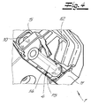
- the housing as such may be formed in two parts with lock housing and lock (housing) cover, although in principle a one-piece version or three-part variants are conceivable and are encompassed by the inventive concept. If lock housing and lock (housing) cover are realized, the axis between the lever flange and coupling flange between the respective bearing shell halves is held. That is, both the lock housing and the lock (housing) cover have bearing shell halves, each taken together with the combined lock housing and lock (housing) lid form a continuous bearing shell for receiving the axis.
- the inventive special actuation and / or locking lever including coupling element can be placed with its axis, for example, in the lock housing and learns automatically after the union of the lock housing with the lock (housing) cover fixing and simultaneous storage in that in this process the respective bearing shell halves are combined to each axis enclosing the bearing cups.
- the respective bearing shell halves are combined to each axis enclosing the bearing cups.
- two correspondingly constructed bearing shells are realized, in the interior of the housing.
- a locking device for a motor vehicle door lock which in a strikingly simple manner couples the actuating unit, for example the lock cylinder acted on by a key, with the actuating and / or locking lever in the interior of the housing of the motor vehicle door lock. Because only two elements are required for this purpose, namely the transmission element and the coupling element as part of the actuating and / or locking lever.
- the transmission element can be directly and easily connected to the coupling element, so that linear movements of the transmission element or at this point mostly realized outer locking bar are implemented in pivotal movements of the coupling element and thus the outer locking lever , These pivotal movements of the coupling element and thus of the outer locking lever lead in a known manner for taking the functional positions "locked” and "unlocked”.
- the actuating and / or locking lever or outer locking lever may act on a central locking lever and this in the transfer these functional positions.
- the actuating and / or locking lever or outer locking lever thus complements or takes over the function of a drive unit, which is usually associated with the central locking lever, as described in detail in DE 102 30 586 A1. Reference should be made at this point to DE 196 32 781 A1. - All this can be done inexpensively and by simple means, wherein the main advantages of the invention can be seen.
- a locking device for a motor vehicle door lock 1 is shown. From the motor vehicle door lock 1 can be seen only the essential elements of the invention. This is a locking element 2 and an actuating and / or locking lever 3, 4, 5, which in the embodiment as a locking lever 3, 4, 5 or outer locking lever 3, 4, 5 is not restrictive.
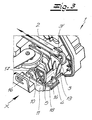
- Pivoting movements of the locking lever 3, 4, 5 and outer locking lever 3, 4, 5 are converted into linear movements of the locking element 2, as indicated in Fig. 3 by a double arrow.
- These linear actuating movements of the locking element 2 cause a with the locking element 2 interacting and merely indicated central locking lever 6 at least its two functional positions or functional states "unlocked” and "locked” occupies. It is insofar referred to the DE 102 30 586 A1 and DE 196 32 781 A1. Thereafter, independently of the locking element 2, an additional drive unit operating on the central locking lever 6 can also "unlock” and "lock” the taking of the functional states described.
- the outer locking lever 3, 4, 5 operates in the present case as the inner locking lever 11 in DE 102 30 586 A1.
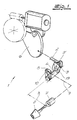
- this actuating unit 7, 8 is a locking cylinder 7, which is acted upon by an associated key 8.
- Rotational movements of the key 8 within the lock cylinder 7 are converted into linear actuating movements of a transmission element 9 connected to the actuation unit 7, 8, in which case it is an outer locking rod 9 in the context of the representation.
- the outer locking bar 9 is connected in the region of a connecting eye 10 to the locking lever 3, 4, 5, in the present case suspended in this. Consequently, rotational movements of the key 8 with respect to the lock cylinder 7 are converted into linear positioning movements of the outer locking bar 9 and subsequently in turn pivotal movements of the locking lever 3, 4, 5 and finally in the linear translational movements of the locking element 2 to the desired locking function state or EntriegelungsfunktionsTalk the central locking lever 6 and Consequently, the motor vehicle door lock 1 as a whole to be able to represent.
- the locking lever 3, 4, 5 has a guided out of a housing 11, 12 of the motor vehicle door lock 1 coupling element 5, which is directly connected to the transmission element 9.
- the locking lever 3, 4, 5 is composed according to the invention of a total of three components, namely a lever flange 3, a coupling flange 5 as a coupling element 5 and an axis or shaft 4 connecting the two flanges 3, 5.
- the lever flange 3, the coupling flange. 5 and finally the axle 4 taken together form a one-piece plastic component.
- the lever flange 3 has a cooperating with the locking element 2 actuating lug 3 ', which engages in a corresponding recess in the locking element 2 for transmitting the rotational movements (see Fig .. 3).
- the lever flange 3 and the coupling flange 5 are rotatably mounted on the common axis 4 and connected to each other with a predetermined overlap in a vertical axial projection to the respective axis 4. That is, in a view from the direction X in Fig. 3 on the locking lever 3, 4, 5, that is, in axial projection, the two flanges 3, 5 have a certain and predetermined overlap.
- the two flanges 3, 5 are connected substantially congruent in this vertical axial projection to the relevant axis 4. This has the consequence that both flanges 3, 5 are pivoted in phase and sweep substantially matching pivoting angle.
- the two flanges 3, 5 are respectively arranged at the end of the axis 4 connecting them, in such a way that the axis 4 connects the two flanges 3, 5 to each other at the foot.
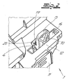
- the coupling flange 5 is shown in FIG. 2 outside the housing 11, 12 of the motor vehicle door lock 1, while the lever flange 3 is located in the interior of the relevant housing 11, 12.
- Respective limiting webs 13 to the Flanges 3, 5 in conjunction with the housing 11, 12 ensure that the locking lever 3, 4, 5 is held in the axial direction as a whole. Because the respective boundary webs 13 abut against associated walls of the housing 11, 12.
- the housing 11, 12 consists of a lock housing 11 and a lock cover 12 together, which form the housing 11, 12 for the motor vehicle door lock 1 in total after their mostly latching association. Both the lock housing 11 and the lock cover 12 now have the mentioned bearing shell halves 14, 15. In this case, the lock housing 11, the bearing shell halves 14, while the lock cover 12 has the bearing shell halves 15.
- the locking lever 3, 4, 5 undergoes both axial support (by the webs 13) and a radial bearing as a result of the bearing shells 14, 15 in the union of the lock housing 11 with the lock cover 12th
- the coupling flange 5 is arranged in a receptacle 16, which has corresponding boundaries 17, 18.
- the pivotal angle swept by the coupling flange 5 is limited to values of approximately 90 °.
- other pivot angle limitations can be realized.
- the receptacle 16 is sealed against the interior of the housing 11, 12. Only the axis 4 is namely through an opening 19 of the housing 11, 12 guided in the receptacle 16 in question. To seal the opening 19 of the housing 11, 12 serves a merely indicated shaft seal 20 (see Fig. 2).
- the transmission element 9 and consequently the outer locking bar 9 can be made variable in length.
- the rod 9 in question in a modular manner or simply to work for different applications with interchangeable rods or transmission elements 9.
- the locking device described can be universally used as long as it is only ensured that the motor vehicle door lock 1 to be actuated with the special locking lever 3, 4, 5 with located inside the housing 11, 12 lever flange 3 and externally arranged coupling flange. 5 equipped.
Landscapes
- Lock And Its Accessories (AREA)
Abstract
Description
- Die Erfindung betrifft eine Verriegelungseinrichtung für ein Kraftfahrzeugtürschloss, mit einer Betätigungseinheit, z. B. von einem Schlüssel beaufschlagbarer Schließzylinder, und mit einem im Gehäuse des Kraftfahrzeugtürschlosses angeordneten Betätigungs- und/oder Verriegelungshebel, auf welchen ein Übertragungselement zwischen Betätigungseinheit und Kraftfahrzeugtürschloss arbeitet. Der Betätigungs- und/oder Verriegelungshebel ist üblicherweise Bestandteil einer Betätigungskette und/oder Verriegelungskette, um verschiedene Funktionszustände des Kraftfahrzeugtürschlosses darstellen zu können. Im Falle eines Verriegelungshebels handelt es sich hier wenigstens um eine Verriegelungsfunktion und Entriegelungsfunktion.
- Sofern ein Verriegelungshebel zum Einsatz kommt, ist dieser regelmäßig und nicht einschränkend als Außenverriegelungshebel ausgebildet, stellt also einen Verriegelungshebel dar, mit dessen Hilfe ein Gesperre im Innern des Kraftfahrzeugtürschlosses von außen her in seinen Verriegelungsfunktionszustand oder seinen Entriegelungsfunktionszustand überführt werden kann. Der erstgenannte Funktionszustand korrespondiert wie üblich dazu, dass regelmäßig ein Türaußengriff sowie ein Türinnengriff leer gehen bzw. erst eine Entriegelung vorgenommen werden muss, bevor das Gesperre geöffnet werden kann. Dabei wird ein Ver- und Entriegelungswunsch üblicherweise von einem Schließzylinder inklusive Schlüssel als Betätigungseinheit unter Zwischenschaltung des Übertragungselementes an den Verriegelungshebel bzw. Außenverriegelungshebel weitergeleitet. Das Übertragungselement kann grundsätzlich jedwede Ausgestaltung besitzen, beispielsweise als Bowdenzug, Gestänge etc. ausgeführt sein.
- Im gattungsbildenden Stand der Technik, wie er beispielsweise in der DE 198 23 188 C2, der EP 0 364 936 B2 oder auch der DE 102 30 586 A1 beschrieben wird, greift das Übertragungselement in Gestalt einer Verbindungswelle oder Verbindungsstange in eine Schaltnuss bzw. Schlossnuss ein, die im Gehäuse des Kraftfahrzeugtürschlosses drehbar gelagert ist und ihre Drehbewegungen ins Innere auf einen angeschlossenen Betätigungs- und/oder Verriegelungshebel überträgt.
- Die Schlossnuss ist im Vergleich zum Gehäuse für das Kraftfahrzeugtürschloss offen gestaltet, so dass das Übertragungselement hierin beispielsweise mit einem Paddel eingreifen kann, wie dies im weiteren einschlägigen Stand der Technik entsprechend der EP 1 004 729 A1 im Detail erläutert wird. Vergleichbar geht die EP 1 262 616 A2 vor. Zu erwähnen ist auch noch die DE 42 22 798 C2.
- Der bisher bekannte Stand der Technik hat sich grundsätzlich bewährt, was die Anbindung des im Gehäuse befindlichen Betätigungs- und/oder Verriegelungshebels an das von außen angeschlossene Übertragungselement angeht. Denn in diesem Zusammenhang sorgt zumeist die Schlossnuss für eine abgedichtete Übertragung von Drehbewegungen des Paddels auf den betreffenden Betätigungs- und/oder Verriegelungshebel, wie dies im Einzelnen in der EP 0 364 936 B2, der DE 198 23 188 C2 oder auch der DE 36 28 376 A1 erläutert wird. Allerdings ist die an dieser Stelle üblicherweise realisierte Verbindungswelle nur in der Lage, geringfügige Höhendifferenzen zwischen einerseits der Betätigungseinheit bzw. dem Schließzylinder und andererseits dem Gehäuse bzw. dem Kraftfahrzeugtürschloss im Ganzen ausgleichen zu können. Dieser Umstand führt dazu, dass jeder Anwendungsfall spezielle Einbauteile erfordert.
- Um auch größere Höhendifferenzen zwischen der Betätigungseinheit und dem Kraftfahrzeugtürschloss überbrücken zu können greift der weiter genannte Stand der Technik nach der EP 1 262 616 A2 ergänzend auf ein Übertragungsteil zwischen Schließzylinder und Schlossmechanismus zurück, welches sich aus drehfest sowohl mit dem Schließzylinder als auch mit dem Schlossmechanismus verbundenen Drehteilen zusammensetzt. Die Drehteile sind zahnradartig aufgebaut und weisen zumindest bereichsweise eine Verzahnung an ihrem Umfang auf.
- Alternativ hierzu schlägt die EP 1 004 729 A1 einen Kabelantrieb zur Distanzüberbrückung zwischen dem Schließzylinder und einem das Paddel aufnehmenden Tragteil vor. - Das ist wiederum aufwendig und erfordert spezielle Einbau- und Übertragungsteile für jeden Anwendungsfall.
- Denn beide zuvor angegebenen Varianten zur Übertragung der Drehbewegung des Schließzylinders bzw. allgemein einer Betätigungseinheit auf den Betätigungs- und/oder Verriegelungshebel im Innern des Gehäuses für das Kraftfahrzeugtürschloss sind mechanisch kompliziert aufgebaut und lassen sich zudem nur mit erheblichen Kosten realisieren. Hinzu kommt, dass das Übertragungselement auf eine Vielzahl von speziellen Einzelbauteilen zurückgreift, deren jeweilige Funktion sowie ihr Zusammenspiel über das Kraftfahrzeugleben gesehen fraglich sind. Neben einer aufwendigen Bauweise kann also auch nicht immer eine sichere Funktionsweise gewährleistet werden. Hier will die Erfindung insgesamt Abhilfe schaffen.
- Der Erfindung liegt das technische Problem zugrunde, eine gattungsgemäße Verriegelungseinrichtung für ein Kraftfahrzeugtürschloss so weiter zu entwickeln, dass auf einfache und kostengünstige Weise beliebige Höhendifferenzen zwischen einerseits der Betätigungseinheit und andererseits dem Kraftfahrzeugtürschloss überbrückt werden können.
- Zur Lösung dieser technischen Problemstellung ist eine gattungsgemäße Verriegelungseinrichtung im Rahmen der Erfindung dadurch gekennzeichnet, dass der Betätigungs- und/oder Verriegelungshebel ein aus dem Gehäuse des Kraftfahrzeugtürschlosses herausgeführtes Koppelelement zur unmittelbaren Verbindung mit dem Übertragungselement aufweist. Das heißt, das Koppelelement ist Bestandteil des Betätigungs- und/oder Verriegelungshebels, wobei Betätigungs- und/oder Verriegelungshebel und Koppelelement vorteilhaft - aber nicht zwingend - einstückig ausgebildet sind.
- In diesem Zusammenhang verfügt das Aggregat aus Betätigungs- und/oder Verriegelungshebel und Koppelelement in der Regel über einen Hebelflansch und einen Koppelflansch als Koppelelement, wobei die Flansche durch eine Achse bzw. Welle miteinander verbunden sind. Das heißt, der Betätigungs- und/oder Verriegelungshebel und das Koppelelement sind auf dieser gemeinsamen Achse drehbar gelagert. Dabei wird in der Regel lediglich die vorgenannte Achse aus dem Gehäuse herausgeführt und kann insofern problemlos abgedichtet werden. In diesem Zusammenhang hat es sich bewährt, wenn jeweils endseitig der Achse einerseits der Koppelflansch außerhalb des Gehäuses und andererseits der Hebelflansch innerhalb des Gehäuses für das Kraftfahrzeugtürschloss an die Achse angeschlossen sind.
- Dadurch muss lediglich die Achse gegenüber dem Gehäuse abgedichtet werden, was problemlos durch beispielsweise eine oder mehrere Wellendichtungen gelingt. Auf diese Weise lässt sich das Gehäuse für das Kraftfahrzeugtürschloss problemlos und kostengünstig abdichten, wobei vergleichbare Vorteile wie bei der bekannten Übertragungselement/Schlossnusskombination geltend gemacht werden können. Das heißt, der betreffende Hebel ist staub- sowie wasserdicht an das Übertragungselement angebunden. Außerdem gewährleistet der spezielle Betätigungs- und/oder Verriegelungshebel inklusive Koppelelement eine akustische Entkopplung von einerseits Betätigungseinheit und andererseits Kraftfahrzeugtürschloss bzw. von dem Betätigungs- und/oder Verriegelungshebel beaufschlagten Schlosselementen im Innern des zugehörigen Gehäuses.
- Ergänzend hat es sich bewährt, wenn der Betätigungs- und/oder Verriegelungshebel und das Koppelelement zusammengenommen ein einstückiges Kunststoffbauteil bilden. Dadurch lassen sich die Fertigungskosten noch einmal deutlich verringern, insbesondere, wenn man die erfindungsgemäße Lösung mit den bekannten Varianten vergleicht. Hinzu kommt, dass mit dem Koppelelement ein einfach und preisgünstig herzustellendes Übertragungselement, beispielsweise eine Außenverriegelungsstange, verbunden werden kann.
- Dabei ist es sogar möglich, dass das Übertragungselement bzw. die Außenverriegelungsstange je nach topologischer Lage von einerseits Kraftfahrzeugtürschloss und andererseits Betätigungseinheit zueinander längenvariabel ausgebildet ist. Das heißt, es kommt üblicherweise eine längenveränderliche Verbindungsstange, insbesondere Außenverriegelungsstange, zum Einsatz. Genauso gut kann auf modular austauschbare Verbindungsstangen bzw. Übertragungselemente zur Anpassung an die jeweilige Einbausituation zurückgegriffen werden.
- Der Hebelflansch und der Koppelflansch können mit vorgegebener Überlappung zueinander in senkrechter axialer Projektion an die sie verbindende Achse angeschlossen sein. Dadurch werden von dem Übertragungselement auf den Koppelflansch übertragene Schwenkbewegungen gleichphasig und im Wesentlichen unter Berücksichtigung eines vergleichbaren Schwenkwinkels unmittelbar auf den Hebelflansch übermittelt, welcher seinerseits an ein Verriegelungshebelwerk angeschlossen sein kann oder über ein Verriegelungselement beispielsweise einen Zentralverriegelungshebel in die gewünschten Positionen "verriegelt" oder "entriegelt" überführt. Ebenso gut können Hebelflansch und Zentralverriegelungshebel unmittelbar miteinander gekoppelt sein oder unter Umständen sogar ein Bauteil formen.
- Das Koppelelement bzw. der Koppelflansch ist üblicherweise in einer seine Schwenkbewegungen begrenzenden Aufnahmewanne des Schlossgehäuses angeordnet. Dadurch wird erreicht, dass nur ein kopfseitiger Bereich des Koppelelementes gegenüber dem Schlossgehäuse vorkragt. Dieser kopfseitige Bereich des Koppelelementes bzw. des Koppelflansches verfügt in der Regel über eine Verbindungsöse zum Anschluss des Übertragungselementes. Die Aufnahmewanne stellt sicher, dass das Koppelelement nur innerhalb eines durch die Aufnahmewanne begrenzten Schwenkbereiches hin- und herbewegt werden kann. Gleiches gilt dann natürlich auch für den Hebelflansch. Dadurch lassen sich Beschädigungen im Innern des Kraftfahrzeugtürschlosses durch übermäßige Schwenkbewegungen des Koppelelementes und folglich des Betätigungs- und/oder Verriegelungshebels im Ganzen zuverlässig verhindern.
- Die genannte Aufnahmewanne ist gegenüber dem Innern des Gehäuses abgedichtet, weil lediglich die Achse durch eine Öffnung des Gehäuses in die Aufnahmewanne geführt wird. Zur Abdichtung der Achse gegenüber der betreffenden Öffnung dient die bereits angesprochene Wellendichtung bzw. die mehreren Wellendichtungen.
- Das Gehäuse als solches kann zweiteilig mit Schlossgehäuse und Schloss(gehäuse)deckel ausgebildet sein, wenngleich grundsätzlich auch eine einteilige Version oder auch dreiteilige Varianten denkbar sind und vom Erfindungsgedanken umfasst werden. Sofern Schlossgehäuse und Schloss(gehäuse)deckel realisiert sind, wird die Achse zwischen Hebelflansch und Koppelflansch zwischen jeweiligen Lagerschalenhälften gehalten. Das heißt, sowohl das Schlossgehäuse als auch der Schloss(gehäuse)deckel verfügen über Lagerschalenhälften, die jeweils zusammengenommen bei vereinigtem Schlossgehäuse und Schloss(gehäuse)deckel eine durchgängige Lagerschale zur Aufnahme der Achse formen.
- Bei der Montage kann folglich der erfindungsgemäße spezielle Betätigungs- und/oder Verriegelungshebel inklusive Koppelelement mit seiner Achse beispielsweise im Schlossgehäuse platziert werden und erfährt automatisch nach der Vereinigung des Schlossgehäuses mit dem Schloss(gehäuse)deckel eine Fixierung und gleichzeitige Lagerung dadurch, dass bei diesem Vorgang die jeweiligen Lagerschalenhälften zu jeweils die Achse insgesamt umgreifenden Lagerschalen vereinigt werden. Meist sind zwei entsprechend aufgebaute Lagerschalen realisiert, und zwar im Innern des Gehäuses.
- Im Ergebnis wird eine Verriegelungseinrichtung für ein Kraftfahrzeugtürschloss zur Verfügung gestellt, die auf frappierend einfache Art und Weise die Betätigungseinheit, beispielsweise den von einem Schlüssel beaufschlagten Schließzylinder, mit dem Betätigungs- und/oder Verriegelungshebel im Innern des Gehäuses des Kraftfahrzeugtürschlosses koppelt. Denn zu diesem Zweck sind lediglich zwei Elemente erforderlich, nämlich das Übertragungselement sowie das Koppelelement als Bestandteil des Betätigungs- und/oder Verriegelungshebels.
- Dadurch, dass das Koppelelement außerhalb des Gehäuses geführt und gelagert ist, lässt sich das Übertragungselement unmittelbar und einfach mit dem Koppelelement verbinden, so dass regelmäßig Linearbewegungen des Übertragungselementes bzw. der an dieser Stelle zumeist realisierten Außenverriegelungsstange in Schwenkbewegungen des Koppelelementes und damit des Außenverriegelungshebels umgesetzt werden. Diese Schwenkbewegungen des Koppelelementes und folglich des Außenverriegelungshebels führen in bekannter Art und Weise zur Einnahme der Funktionsstellungen "verriegelt" und "entriegelt".
- Dazu mag der Betätigungs- und/oder Verriegelungshebel bzw. Außenverriegelungshebel an einem Zentralverriegelungshebel angreifen und diesen in die genannten Funktionsstellungen überführen. In diesem Zusammenhang ergänzt bzw. übernimmt der Betätigungs- und/oder Verriegelungshebel bzw. Außenverriegelungshebel also die Funktion einer dem Zentralverriegelungshebel zumeist zugeordneten Antriebseinheit, wie dies im Detail in der DE 102 30 586 A1 beschrieben wird. Verwiesen sei an dieser Stelle auch auf die DE 196 32 781 A1. - Das alles gelingt preisgünstig und mit einfachen Mitteln, worin die wesentlichen Vorteile der Erfindung zu sehen sind.
- Im Folgenden wird die Erfindung anhand einer lediglich ein Ausführungsbeispiel darstellenden Zeichnung näher erläutert; es zeigen:
- Fig. 1
- die erfindungsgemäße Verriegelungseinrichtung schematisch,
- Fig. 2
- eine Ansicht des Gehäuses für das Kraftfahrzeugtürschloss mit Koppelelement und
- Fig. 3 und 4
- perspektivische Detailansichten des Betätigungs- und/oder Verriegelungshebels inklusive Koppelelement.
- In den Figuren ist eine Verriegelungseinrichtung für ein Kraftfahrzeugtürschloss 1 dargestellt. Von dem Kraftfahrzeugtürschloss 1 erkennt man nur die für die Erfindung wesentlichen Elemente. Hierbei handelt es sich um ein Verriegelungselement 2 und einen Betätigungs- und/oder Verriegelungshebel 3, 4, 5, welcher im Rahmen des Ausführungsbeispiels als Verriegelungshebel 3, 4, 5 bzw. Außenverriegelungshebel 3, 4, 5 nicht einschränkend ausgebildet ist.
- Schwenkbewegungen des Verriegelungshebels 3, 4, 5 bzw. Außenverriegelungshebels 3, 4, 5 werden in Linearbewegungen des Verriegelungselementes 2 umgesetzt, wie dies in Fig. 3 durch einen Doppelpfeil angedeutet ist. Diese Linearstellbewegungen des Verriegelungselementes 2 führen dazu, dass ein mit dem Verriegelungselement 2 wechselwirkender und lediglich angedeuteter Zentralverriegelungshebel 6 zumindest seine beiden Funktionsstellungen bzw. Funktionszustände "entriegelt" und "verriegelt" einnimmt. Es wird insofern verwiesen auf die DE 102 30 586 A1 sowie die DE 196 32 781 A1. Danach kann unabhängig von dem Verriegelungselement 2 eine zusätzliche und auf den Zentralverriegelungshebel 6 arbeitende Antriebseinheit ebenfalls für die Einnahme der beschriebenen Funktionszustände "entriegelt" und "verriegelt" sorgen. Der Außenverriegelungshebel 3, 4, 5 arbeitet vorliegend so wie der Innenverriegelungshebel 11 bei der DE 102 30 586 A1.
- Um nun den Verriegelungshebel 3, 4, 5 zu verschwenken und dadurch die linearen Stellbewegungen des angeschlossenen Verriegelungselementes 2 zu bewirken, ist eine Betätigungseinheit 7, 8 vorgesehen. Bei dieser Betätigungseinheit 7, 8 handelt es sich im Rahmen des Ausführungsbeispiels und nicht einschränkend um einen Schließzylinder 7, welcher von einem zugehörigen Schlüssel 8 beaufschlagt wird.
- Drehbewegungen des Schlüssels 8 innerhalb des Schließzylinders 7 werden in lineare Stellbewegungen eines an die Betätigungseinheit 7, 8 angeschlossenen Übertragungselementes 9 umgewandelt, bei welchem es sich im Rahmen der Darstellung um eine Außenverriegelungsstange 9 handelt. Die Außenverriegelungsstange 9 ist im Bereich einer Verbindungsöse 10 an den Verriegelungshebel 3, 4, 5 angeschlossen, vorliegend in diesen eingehängt. Folglich werden Drehbewegungen des Schlüssels 8 gegenüber dem Schließzylinder 7 in lineare Stellbewegungen der Außenverriegelungsstange 9 umgewandelt und daran anschließend wiederum in Schwenkbewegungen des Verriegelungshebels 3, 4, 5 und schließlich in die linearen Translationsbewegungen des Verriegelungselementes 2, um den gewünschten Verriegelungsfunktionszustand oder Entriegelungsfunktionszustand des Zentralverriegelungshebels 6 und folglich des Kraftfahrzeugtürschlosses 1 im Ganzen darstellen zu können.
- Für die Erfindung von besonderer Bedeutung ist der Umstand, dass der Verriegelungshebel 3, 4, 5 über ein aus einem Gehäuse 11, 12 des Kraftfahrzeugtürschlosses 1 herausgeführtes Koppelelement 5 verfügt, welches unmittelbar mit dem Übertragungselement 9 verbunden ist. Tatsächlich setzt sich der Verriegelungshebel 3, 4, 5 erfindungsgemäß aus insgesamt drei Bestandteilen zusammen, nämlich einem Hebelflansch 3, einem Koppelflansch 5 als Koppelelement 5 sowie einer die beiden Flansche 3, 5 verbindenden Achse bzw. Welle 4. Der Hebelflansch 3, der Koppelflansch 5 und schließlich die Achse 4 bilden zusammengenommen ein einstückiges Kunststoffbauteil. Der Hebelflansch 3 verfügt über eine mit dem Verriegelungselement 2 zusammenwirkende Betätigungsnase 3', welche in eine korrespondierende Ausnehmung im Verriegelungselement 2 zur Übertragung der Drehbewegungen eingreift (vgl. Fig. 3).
- Der Hebelflansch 3 und der Koppelflansch 5 sind auf der gemeinsamen Achse 4 drehbar gelagert und mit vorgegebener Überlappung zueinander in senkrechter axialer Projektion an die betreffende Achse 4 angeschlossen. Das heißt, bei einem Blick aus Richtung X in Fig. 3 auf den Verriegelungshebel 3, 4, 5, das heißt in axialer Projektion, verfügen die beiden Flansche 3, 5 über einen bestimmten und vorgegebenen Überlapp. Im Rahmen des Ausführungsbeispiels sind die beiden Flansche 3, 5 im Wesentlichen deckungsgleich in dieser senkrechten axialen Projektion an die betreffende Achse 4 angeschlossen. Das hat zur Folge, dass beide Flansche 3, 5 gleichphasig verschwenkt werden und im Wesentlichen übereinstimmende Schwenkwinkel überstreichen.
- Man erkennt, dass die beiden Flansche 3, 5 jeweils endseitig der sie verbindenden Achse 4 angeordnet sind, und zwar so, dass die Achse 4 beide Flansche 3, 5 fußseitig miteinander verbindet. Dabei ist der Koppelflansch 5 ausweislich der Fig. 2 außerhalb des Gehäuses 11, 12 des Kraftfahrzeugtürschlosses 1 angeordnet, während sich der Hebelflansch 3 im Innern des betreffenden Gehäuses 11, 12 befindet. Jeweilige Begrenzungsstege 13 an den Flanschen 3, 5 sorgen in Verbindung mit dem Gehäuse 11, 12 dafür, dass der Verriegelungshebel 3, 4, 5 insgesamt in axialer Richtung gehalten wird. Denn die betreffenden Begrenzungsstege 13 liegen an zugehörigen Wänden des Gehäuses 11, 12 an.
- Zur Lagerung des Verriegelungshebels 3, 4, 5 sind Lagerschalenhälften 14, 15 vorgesehen. Tatsächlich setzt sich das Gehäuse 11, 12 aus einem Schlossgehäuse 11 sowie einem Schlossdeckel 12 zusammen, die nach ihrer zumeist rastenden Vereinigung insgesamt das Gehäuse 11, 12 für das Kraftfahrzeugtürschloss 1 formen. Sowohl das Schlossgehäuse 11 als auch der Schlossdeckel 12 verfügen nun über die angesprochenen Lagerschalenhälften 14, 15. Dabei weist das Schlossgehäuse 11 die Lagerschalenhälften 14 auf, während der Schlossdeckel 12 über die Lagerschalenhälften 15 verfügt.
- Beide Lagerschalenhälften 14, 15 zusammengenommen bilden nach der Vereinigung von Schlossgehäuse 11 und Schlossdeckel 12 jeweils eine die Achse 4 vollständig umgreifende Lagerschale 14, 15, wie in Fig. 4 angedeutet ist. Auf diese Weise erfährt der Verriegelungshebel 3, 4, 5 eine sowohl axiale Halterung (durch die Stege 13) als auch eine radiale Lagerung in Folge der Lagerschalen 14, 15 bei der Vereinigung des Schlossgehäuses 11 mit dem Schlossdeckel 12.
- Um übermäßige Schwenkbewegungen des Verriegelungshebels 3, 4, 5 zu unterdrücken, ist der Koppelflansch 5 in einer Aufnahmewanne 16 angeordnet, die über entsprechende Begrenzungen 17, 18 verfügt. Dadurch wird der vom Koppelflansch 5 überstreichbare Schwenkwinkel auf Werte von ca. 90° begrenzt. Gleiches gilt für den Verriegelungsflansch 3. Selbstverständlich lassen sich auch andere Schwenkwinkelbegrenzungen realisieren.
- Die Aufnahmewanne 16 ist gegenüber dem Innern des Gehäuses 11, 12 abgedichtet. Lediglich die Achse 4 wird nämlich durch eine Öffnung 19 des Gehäuses 11, 12 in die betreffende Aufnahmewanne 16 geführt. Zur Abdichtung der Öffnung 19 des Gehäuses 11, 12 dient dabei eine lediglich angedeutete Wellendichtung 20 (vgl. Fig. 2).
- Je nach topologischer Lage von einerseits Kraftfahrzeugtürschloss 1 und andererseits Betätigungseinheit 7, 8 zueinander kann das Übertragungselement 9 und folglich die Außenverriegelungsstange 9 längenvariabel ausgeführt sein. Dazu ist es denkbar, die betreffende Stange 9 beispielsweise modular auszuführen oder schlicht und ergreifend für unterschiedliche Anwendungsfälle mit jeweils austauschbaren Stangen bzw. Übertragungselementen 9 zu arbeiten. Auf diese Weise kann die beschriebene Verriegelungseinrichtung gleichsam universell zum Einsatz kommen, solange nur dafür gesorgt wird, dass das zu betätigende Kraftfahrzeugtürschloss 1 mit dem speziellen Verriegelungshebel 3, 4, 5 mit im Innern des Gehäuses 11, 12 befindlichen Hebelflansch 3 und außerhalb angeordnetem Koppelflansch 5 ausgerüstet ist.
- Die Fig. 1 deutet ergänzend an, dass beliebige Abstände bzw. Höhendifferenzen h zwischen einerseits der Betätigungseinheit 7, 8 und andererseits dem Verriegelungshebel 3, 4, 5 bzw. dessen Achse 4 und mithin dem Kraftfahrzeugtürschloss 1 im Ganzen überbrückt werden können. Denn hierzu verfügen beide vorgenannten Elemente 3, 4, 5; 7, 8 über gleichsam standardisierte Schnittstellen, einerseits in Gestalt des Koppelflansches 5 und andererseits in Gestalt des Schließzylinders 7 bzw. eines dort gegebenenfalls vorgesehenen Hebels oder Anschlusselementes. Immer wird eine Drehbewegung der Betätigungseinheit 7, 8 in eine Linearbewegung des Übertragungselementes 9 umgewandelt. Diese Linearbewegung des Übertragungselementes 9 wird dann wiederum in eine Drehbewegung des Betätigungs- und/oder Verriegelungshebels 3, 4, 5 und folglich eine Drehbewegung dessen Achse bzw. Welle 4 umgesetzt.
- Drehbewegungen der Achse bzw. Welle 4 führen dann zu Linearbewegungen des Verriegelungselementes 2 bzw. Betätigungselementes 2, die im Beispielfall in die gewünschten Funktionsstellungen des Zentralverriegelungshebels 6 münden. Dabei ist von besonderer Bedeutung, dass durch die standardisierten Schnittstellen verschiedene Einbausituationen lediglich ein an den Abstand bzw. die Höhendifferenz h angepasstes Übertragungselement 9 erfordern, welches zudem als Option längenvariabel ausgebildet sein kann. Das heißt, die Bezeichnung h meint eine Abstands- und/oder Höhendifferenz zwischen einerseits der Betätigungseinheit 7, 8 und andererseits dem Kraftfahrzeugtürschloss 1.
Claims (10)
- Verriegelungseinrichtung für ein Kraftfahrzeugtürschloss (1), mit einer Betätigungseinheit (7, 8), und mit einem im Gehäuse (11, 12) des Kraftfahrzeugtürschlosses (1) angeordneten Betätigungs- und/oder Verriegelungshebel (3, 4, 5), auf welchen ein Übertragungselement (9) zwischen Betätigungseinheit (7, 8) und Kraftfahrzeugtürschloss (1) arbeitet, dadurch gekennzeichnet, dass der Betätigungs- und/oder Verriegelungshebel (3, 4, 5) ein aus dem Gehäuse (11, 12) herausgeführtes Koppelelement (5) zur unmittelbaren Verbindung mit dem Übertragungselement (9) aufweist.
- Verriegelungseinrichtung nach Anspruch 1, dadurch gekennzeichnet, dass der Betätigungs- und/oder Verriegelungshebel (3, 4, 5) einen Hebelflansch (3) und einen Koppelflansch (5) als Koppelelement (5) sowie eine die beiden Flansche (3, 5) verbindende Achse (4) aufweist.
- Verriegelungseinrichtung nach Anspruch 1 oder 2, dadurch gekennzeichnet, dass der Hebelflansch (3) und der Koppelflansch (5) mit vorgegebener Überlappung zueinander in senkrechter axialer Projektion an die Achse (4) angeschlossen sind.
- Verriegelungseinrichtung nach einem Ansprüche 1 bis 3, dadurch gekennzeichnet, dass der Hebelflansch (3) und der Koppelflansch (5) in Verbindung mit der Achse (4) zusammengenommen ein einstückiges Kunststoffbauteil bilden.
- Verriegelungseinrichtung nach einem der Ansprüche 1 bis 4, dadurch gekennzeichnet, dass der Koppelflansch (5) außerhalb des Gehäuses (11, 12) angeordnet ist, während sich der Hebelflansch (3) im Innern befindet.
- Verriegelungseinrichtung nach einem der Ansprüche 1 bis 5, dadurch gekennzeichnet, dass der Koppelflansch (5) in einer seine Schwenkbewegungen begrenzenden Aufnahmewanne (16) des Gehäuses (11, 12) angeordnet ist.
- Verriegelungseinrichtung nach einem der Ansprüche 1 bis 6, dadurch gekennzeichnet, dass der Betätigungs- und/oder Verriegelungshebel (3, 4, 5) gegenüber dem Innern des Gehäuses (11, 12) abgedichtet ist, in dem lediglich die Achse (4) durch eine Öffnung (19) geführt wird.
- Verriegelungseinrichtung nach einem der Ansprüche 1 bis 7, dadurch gekennzeichnet, dass der Koppelflansch (5) eine Verbindungsöse (10) zum Anschluss des Übertragungselementes (9) und der Hebelflansch (3) eine mit einem Verriegelungselement (2) zusammenwirkende Betätigungsnase (3') aufweist.
- Verriegelungseinrichtung nach einem der Ansprüche 1 bis 8, dadurch gekennzeichnet, dass das Gehäuse (11, 12) zweiteilig mit Schlossgehäuse (11) und Schlossdeckel (12) ausgebildet ist, wobei die Achse (4) zwischen jeweiligen Lagerschalenhälften (14, 15) gehalten wird.
- Verriegelungseinrichtung nach einem der Ansprüche 1 bis 9, dadurch gekennzeichnet, dass das Übertragungselement (9) je nach topologischer Lage von einerseits Kraftfahrzeugtürschloss (1) und andererseits Betätigungseinheit (7, 8) zueinander längenvariabel ausgebildet ist.
Applications Claiming Priority (1)
| Application Number | Priority Date | Filing Date | Title |
|---|---|---|---|
| DE200410027381 DE102004027381A1 (de) | 2004-06-04 | 2004-06-04 | Verriegelungseinrichtung für ein Kraftfahrzeugtürschloss |
Publications (3)
| Publication Number | Publication Date |
|---|---|
| EP1612349A2 true EP1612349A2 (de) | 2006-01-04 |
| EP1612349A3 EP1612349A3 (de) | 2009-10-28 |
| EP1612349B1 EP1612349B1 (de) | 2015-11-04 |
Family
ID=35240944
Family Applications (1)
| Application Number | Title | Priority Date | Filing Date |
|---|---|---|---|
| EP05011567.4A Expired - Lifetime EP1612349B1 (de) | 2004-06-04 | 2005-05-30 | Verriegelungseinrichtung für ein Kraftfahrzeugtürschloss |
Country Status (2)
| Country | Link |
|---|---|
| EP (1) | EP1612349B1 (de) |
| DE (1) | DE102004027381A1 (de) |
Families Citing this family (2)
| Publication number | Priority date | Publication date | Assignee | Title |
|---|---|---|---|---|
| DE102009028838B4 (de) * | 2009-08-24 | 2023-04-13 | Kiekert Aktiengesellschaft | Ausgleichsgetriebe für Kraftfahrzeugtürschloss und Kraftfahrzeugschloss |
| US11078694B2 (en) | 2016-06-10 | 2021-08-03 | Kiekert Ag | Motor vehicle door lock |
Citations (7)
| Publication number | Priority date | Publication date | Assignee | Title |
|---|---|---|---|---|
| DE3628376A1 (de) | 1986-08-21 | 1988-02-25 | Daimler Benz Ag | Tuergriffanordnung fuer tueren von kraftwagen |
| EP0364936A2 (de) | 1988-10-20 | 1990-04-25 | BOMORO Bocklenberg & Motte GmbH & Co. KG | Kraftfahrzeug-Türschloss |
| DE4222798A1 (de) | 1992-07-10 | 1994-01-13 | Daimler Benz Ag | Baugruppe aus einem Schloß und einem Stellelement |
| DE19823188A1 (de) | 1998-05-23 | 1999-12-02 | Kiekert Ag | Kraftfahrzeugtürverschluß |
| EP1004729A1 (de) | 1998-11-25 | 2000-05-31 | Rover Group Limited | Verriegelung für ein Kraftfahrzeugschliesssystem |
| EP1262616A2 (de) | 2001-06-01 | 2002-12-04 | Huf Hülsbeck & Fürst GmbH & Co. KG | Schliessvorrichtung |
| DE10230586A1 (de) | 2002-07-05 | 2004-01-22 | Kiekert Ag | Kraftfahrzeugtürverschluss |
Family Cites Families (13)
| Publication number | Priority date | Publication date | Assignee | Title |
|---|---|---|---|---|
| GB1296556A (de) * | 1969-02-13 | 1972-11-15 | ||
| JPS5833679A (ja) * | 1981-08-19 | 1983-02-26 | 日産自動車株式会社 | 自動車の防盗装置 |
| US4602887A (en) * | 1985-06-10 | 1986-07-29 | General Motors Corporation | Fastening arrangement for vehicle body door latch system |
| US4885954A (en) * | 1987-12-09 | 1989-12-12 | Wanlass Bert R | Door lock actuator |
| JP2616598B2 (ja) * | 1991-05-14 | 1997-06-04 | 三菱電機株式会社 | モータ式アクチュエータ |
| DE4222051C2 (de) * | 1992-02-20 | 1999-05-27 | Kiekert Ag | Kraftfahrzeugtürverschluß mit spannbarem Öffnungshebel |
| JP2832234B2 (ja) * | 1993-02-05 | 1998-12-09 | 三井金属鉱業株式会社 | 車両用オートドアロック装置 |
| US5715713A (en) * | 1996-01-11 | 1998-02-10 | General Motors Corporation | Door latch locking actuator assembly |
| JP3180028B2 (ja) * | 1996-05-24 | 2001-06-25 | 三井金属鉱業株式会社 | 車両用スライド扉自動開閉装置 |
| EP1105603B1 (de) * | 1998-07-29 | 2003-03-05 | Intier Automotive Closures Inc. | Kraftfahrzeugtürverschluss mit verbesserter diebstahlsicherheit |
| DE10013848B4 (de) * | 2000-03-15 | 2005-09-29 | Brose Fahrzeugteile Gmbh & Co. Kg, Coburg | Schließsystem für eine Kraftfahrzeugtür |
| US6578446B2 (en) * | 2001-08-30 | 2003-06-17 | Delphi Technologies, Inc. | Bell crank assembly and kit |
| FR2860024B1 (fr) * | 2003-09-22 | 2005-11-11 | Valeo Securite Habitacle | Dispositif de condamnation interieure de vehicule automobile a debrayage de la tirette de frise |
-
2004
- 2004-06-04 DE DE200410027381 patent/DE102004027381A1/de not_active Withdrawn
-
2005
- 2005-05-30 EP EP05011567.4A patent/EP1612349B1/de not_active Expired - Lifetime
Patent Citations (7)
| Publication number | Priority date | Publication date | Assignee | Title |
|---|---|---|---|---|
| DE3628376A1 (de) | 1986-08-21 | 1988-02-25 | Daimler Benz Ag | Tuergriffanordnung fuer tueren von kraftwagen |
| EP0364936A2 (de) | 1988-10-20 | 1990-04-25 | BOMORO Bocklenberg & Motte GmbH & Co. KG | Kraftfahrzeug-Türschloss |
| DE4222798A1 (de) | 1992-07-10 | 1994-01-13 | Daimler Benz Ag | Baugruppe aus einem Schloß und einem Stellelement |
| DE19823188A1 (de) | 1998-05-23 | 1999-12-02 | Kiekert Ag | Kraftfahrzeugtürverschluß |
| EP1004729A1 (de) | 1998-11-25 | 2000-05-31 | Rover Group Limited | Verriegelung für ein Kraftfahrzeugschliesssystem |
| EP1262616A2 (de) | 2001-06-01 | 2002-12-04 | Huf Hülsbeck & Fürst GmbH & Co. KG | Schliessvorrichtung |
| DE10230586A1 (de) | 2002-07-05 | 2004-01-22 | Kiekert Ag | Kraftfahrzeugtürverschluss |
Also Published As
| Publication number | Publication date |
|---|---|
| DE102004027381A1 (de) | 2005-12-29 |
| EP1612349B1 (de) | 2015-11-04 |
| EP1612349A3 (de) | 2009-10-28 |
Similar Documents
| Publication | Publication Date | Title |
|---|---|---|
| EP2788567B1 (de) | Kraftfahrzeugtürschloss | |
| EP3201411B1 (de) | Kraftfahrzeugtürverschluss | |
| EP1639218B1 (de) | Schloss für türen oder klappen an fahrzeugen | |
| EP1198652B1 (de) | Kraftfahrzeugtürverschluss | |
| EP3271539B1 (de) | Kraftfahrzeugtür | |
| DE102016124781A1 (de) | Kraftfahrzeugtürschloss | |
| EP3036389A1 (de) | Kraftfahrzeugtürverschluss | |
| WO2016058590A1 (de) | Kraftfahrzeugtürschloss | |
| EP2173955B1 (de) | Kraftfahrzeugtürverschluss | |
| DE202013102505U1 (de) | Zuzieheinrichtung für ein Kraftfahrzeugschloss | |
| EP1629166B1 (de) | Kraftfahrzeugtürverschluss | |
| DE10320445A1 (de) | Mehrfunktionshebel | |
| EP1612349B1 (de) | Verriegelungseinrichtung für ein Kraftfahrzeugtürschloss | |
| DE112010004715T5 (de) | Fahrzeugtürverriegelung | |
| EP4112851B1 (de) | Kraftfahrzeug-schloss, insbesondere kraftfahrzeug-türschloss | |
| WO2016055052A1 (de) | Kraftfahrzeugtürverschluss und verfahren zur montage eines kraftfahrzeugtürverschlussis | |
| DE10339542B4 (de) | Kraftfahrzeugtürverschluss | |
| EP4062016B1 (de) | Kraftfahrzeug-schloss | |
| EP3847328A1 (de) | Antriebseinheit für kraftfahrzeugtechnische anwendungen | |
| EP1619328B1 (de) | Kraftfahrzeugtürverschluss | |
| DE102019116201A1 (de) | Hebelanordnung für kraftfahrzeugtechnische Anwendungen | |
| EP2499315B1 (de) | Kraftfahrzeugtürverschluss | |
| EP2227614B1 (de) | Kraftfahrzeugtürverschluss | |
| EP3901399B1 (de) | Kraftfahrzeugschloss | |
| EP4086413B1 (de) | Verriegelungsvorrichtung |
Legal Events
| Date | Code | Title | Description |
|---|---|---|---|
| PUAI | Public reference made under article 153(3) epc to a published international application that has entered the european phase |
Free format text: ORIGINAL CODE: 0009012 |
|
| AK | Designated contracting states |
Kind code of ref document: A2 Designated state(s): AT BE BG CH CY CZ DE DK EE ES FI FR GB GR HU IE IS IT LI LT LU MC NL PL PT RO SE SI SK TR |
|
| AX | Request for extension of the european patent |
Extension state: AL BA HR LV MK YU |
|
| PUAL | Search report despatched |
Free format text: ORIGINAL CODE: 0009013 |
|
| AK | Designated contracting states |
Kind code of ref document: A3 Designated state(s): AT BE BG CH CY CZ DE DK EE ES FI FR GB GR HU IE IS IT LI LT LU MC NL PL PT RO SE SI SK TR |
|
| AX | Request for extension of the european patent |
Extension state: AL BA HR LV MK YU |
|
| RIC1 | Information provided on ipc code assigned before grant |
Ipc: E05B 65/12 20060101AFI20051114BHEP Ipc: E05B 65/20 20060101ALI20090921BHEP Ipc: E05B 17/04 20060101ALI20090921BHEP |
|
| AKX | Designation fees paid |
Designated state(s): AT BE BG CH CY LI |
|
| 17P | Request for examination filed |
Effective date: 20100415 |
|
| RAP1 | Party data changed (applicant data changed or rights of an application transferred) |
Owner name: KIEKERT AKTIENGESELLSCHAFT |
|
| RBV | Designated contracting states (corrected) |
Designated state(s): AT BE BG CH CY CZ DE DK EE ES FI FR GB GR HU IE IS IT LI LT LU MC NL PL PT RO SE SI SK TR |
|
| REG | Reference to a national code |
Ref country code: DE Ref legal event code: 8566 |
|
| REG | Reference to a national code |
Ref country code: DE Ref legal event code: R079 Ref document number: 502005014993 Country of ref document: DE Free format text: PREVIOUS MAIN CLASS: E05B0065120000 Ipc: E05B0077000000 |
|
| RIC1 | Information provided on ipc code assigned before grant |
Ipc: E05B 85/02 20140101ALI20150325BHEP Ipc: E05B 83/36 20140101ALI20150325BHEP Ipc: E05B 77/00 20140101AFI20150325BHEP |
|
| GRAP | Despatch of communication of intention to grant a patent |
Free format text: ORIGINAL CODE: EPIDOSNIGR1 |
|
| INTG | Intention to grant announced |
Effective date: 20150703 |
|
| GRAS | Grant fee paid |
Free format text: ORIGINAL CODE: EPIDOSNIGR3 |
|
| GRAA | (expected) grant |
Free format text: ORIGINAL CODE: 0009210 |
|
| AK | Designated contracting states |
Kind code of ref document: B1 Designated state(s): AT BE BG CH CY CZ DE DK EE ES FI FR GB GR HU IE IS IT LI LT LU MC NL PL PT RO SE SI SK TR |
|
| REG | Reference to a national code |
Ref country code: GB Ref legal event code: FG4D Free format text: NOT ENGLISH |
|
| REG | Reference to a national code |
Ref country code: CH Ref legal event code: EP |
|
| REG | Reference to a national code |
Ref country code: AT Ref legal event code: REF Ref document number: 759316 Country of ref document: AT Kind code of ref document: T Effective date: 20151115 |
|
| REG | Reference to a national code |
Ref country code: IE Ref legal event code: FG4D Free format text: LANGUAGE OF EP DOCUMENT: GERMAN |
|
| REG | Reference to a national code |
Ref country code: DE Ref legal event code: R096 Ref document number: 502005014993 Country of ref document: DE |
|
| REG | Reference to a national code |
Ref country code: NL Ref legal event code: MP Effective date: 20151104 |
|
| REG | Reference to a national code |
Ref country code: LT Ref legal event code: MG4D |
|
| PG25 | Lapsed in a contracting state [announced via postgrant information from national office to epo] |
Ref country code: LT Free format text: LAPSE BECAUSE OF FAILURE TO SUBMIT A TRANSLATION OF THE DESCRIPTION OR TO PAY THE FEE WITHIN THE PRESCRIBED TIME-LIMIT Effective date: 20151104 Ref country code: NL Free format text: LAPSE BECAUSE OF FAILURE TO SUBMIT A TRANSLATION OF THE DESCRIPTION OR TO PAY THE FEE WITHIN THE PRESCRIBED TIME-LIMIT Effective date: 20151104 Ref country code: IT Free format text: LAPSE BECAUSE OF FAILURE TO SUBMIT A TRANSLATION OF THE DESCRIPTION OR TO PAY THE FEE WITHIN THE PRESCRIBED TIME-LIMIT Effective date: 20151104 Ref country code: IS Free format text: LAPSE BECAUSE OF FAILURE TO SUBMIT A TRANSLATION OF THE DESCRIPTION OR TO PAY THE FEE WITHIN THE PRESCRIBED TIME-LIMIT Effective date: 20160304 Ref country code: ES Free format text: LAPSE BECAUSE OF FAILURE TO SUBMIT A TRANSLATION OF THE DESCRIPTION OR TO PAY THE FEE WITHIN THE PRESCRIBED TIME-LIMIT Effective date: 20151104 |
|
| REG | Reference to a national code |
Ref country code: FR Ref legal event code: PLFP Year of fee payment: 12 |
|
| PG25 | Lapsed in a contracting state [announced via postgrant information from national office to epo] |
Ref country code: FI Free format text: LAPSE BECAUSE OF FAILURE TO SUBMIT A TRANSLATION OF THE DESCRIPTION OR TO PAY THE FEE WITHIN THE PRESCRIBED TIME-LIMIT Effective date: 20151104 Ref country code: SE Free format text: LAPSE BECAUSE OF FAILURE TO SUBMIT A TRANSLATION OF THE DESCRIPTION OR TO PAY THE FEE WITHIN THE PRESCRIBED TIME-LIMIT Effective date: 20151104 Ref country code: PT Free format text: LAPSE BECAUSE OF FAILURE TO SUBMIT A TRANSLATION OF THE DESCRIPTION OR TO PAY THE FEE WITHIN THE PRESCRIBED TIME-LIMIT Effective date: 20160304 Ref country code: PL Free format text: LAPSE BECAUSE OF FAILURE TO SUBMIT A TRANSLATION OF THE DESCRIPTION OR TO PAY THE FEE WITHIN THE PRESCRIBED TIME-LIMIT Effective date: 20151104 Ref country code: GR Free format text: LAPSE BECAUSE OF FAILURE TO SUBMIT A TRANSLATION OF THE DESCRIPTION OR TO PAY THE FEE WITHIN THE PRESCRIBED TIME-LIMIT Effective date: 20160205 |
|
| REG | Reference to a national code |
Ref country code: DE Ref legal event code: R097 Ref document number: 502005014993 Country of ref document: DE |
|
| PG25 | Lapsed in a contracting state [announced via postgrant information from national office to epo] |
Ref country code: BE Free format text: LAPSE BECAUSE OF NON-PAYMENT OF DUE FEES Effective date: 20160531 Ref country code: EE Free format text: LAPSE BECAUSE OF FAILURE TO SUBMIT A TRANSLATION OF THE DESCRIPTION OR TO PAY THE FEE WITHIN THE PRESCRIBED TIME-LIMIT Effective date: 20151104 Ref country code: SK Free format text: LAPSE BECAUSE OF FAILURE TO SUBMIT A TRANSLATION OF THE DESCRIPTION OR TO PAY THE FEE WITHIN THE PRESCRIBED TIME-LIMIT Effective date: 20151104 Ref country code: DK Free format text: LAPSE BECAUSE OF FAILURE TO SUBMIT A TRANSLATION OF THE DESCRIPTION OR TO PAY THE FEE WITHIN THE PRESCRIBED TIME-LIMIT Effective date: 20151104 Ref country code: RO Free format text: LAPSE BECAUSE OF FAILURE TO SUBMIT A TRANSLATION OF THE DESCRIPTION OR TO PAY THE FEE WITHIN THE PRESCRIBED TIME-LIMIT Effective date: 20151104 |
|
| PLBE | No opposition filed within time limit |
Free format text: ORIGINAL CODE: 0009261 |
|
| STAA | Information on the status of an ep patent application or granted ep patent |
Free format text: STATUS: NO OPPOSITION FILED WITHIN TIME LIMIT |
|
| 26N | No opposition filed |
Effective date: 20160805 |
|
| PG25 | Lapsed in a contracting state [announced via postgrant information from national office to epo] |
Ref country code: SI Free format text: LAPSE BECAUSE OF FAILURE TO SUBMIT A TRANSLATION OF THE DESCRIPTION OR TO PAY THE FEE WITHIN THE PRESCRIBED TIME-LIMIT Effective date: 20151104 |
|
| PG25 | Lapsed in a contracting state [announced via postgrant information from national office to epo] |
Ref country code: LU Free format text: LAPSE BECAUSE OF FAILURE TO SUBMIT A TRANSLATION OF THE DESCRIPTION OR TO PAY THE FEE WITHIN THE PRESCRIBED TIME-LIMIT Effective date: 20160530 |
|
| REG | Reference to a national code |
Ref country code: CH Ref legal event code: PL |
|
| GBPC | Gb: european patent ceased through non-payment of renewal fee |
Effective date: 20160530 |
|
| PG25 | Lapsed in a contracting state [announced via postgrant information from national office to epo] |
Ref country code: LI Free format text: LAPSE BECAUSE OF NON-PAYMENT OF DUE FEES Effective date: 20160531 Ref country code: CH Free format text: LAPSE BECAUSE OF NON-PAYMENT OF DUE FEES Effective date: 20160531 |
|
| REG | Reference to a national code |
Ref country code: IE Ref legal event code: MM4A |
|
| REG | Reference to a national code |
Ref country code: FR Ref legal event code: PLFP Year of fee payment: 13 |
|
| PG25 | Lapsed in a contracting state [announced via postgrant information from national office to epo] |
Ref country code: IE Free format text: LAPSE BECAUSE OF NON-PAYMENT OF DUE FEES Effective date: 20160530 Ref country code: GB Free format text: LAPSE BECAUSE OF NON-PAYMENT OF DUE FEES Effective date: 20160530 |
|
| REG | Reference to a national code |
Ref country code: AT Ref legal event code: MM01 Ref document number: 759316 Country of ref document: AT Kind code of ref document: T Effective date: 20160530 |
|
| PG25 | Lapsed in a contracting state [announced via postgrant information from national office to epo] |
Ref country code: AT Free format text: LAPSE BECAUSE OF NON-PAYMENT OF DUE FEES Effective date: 20160530 |
|
| REG | Reference to a national code |
Ref country code: FR Ref legal event code: PLFP Year of fee payment: 14 |
|
| PG25 | Lapsed in a contracting state [announced via postgrant information from national office to epo] |
Ref country code: CY Free format text: LAPSE BECAUSE OF FAILURE TO SUBMIT A TRANSLATION OF THE DESCRIPTION OR TO PAY THE FEE WITHIN THE PRESCRIBED TIME-LIMIT Effective date: 20151104 Ref country code: HU Free format text: LAPSE BECAUSE OF FAILURE TO SUBMIT A TRANSLATION OF THE DESCRIPTION OR TO PAY THE FEE WITHIN THE PRESCRIBED TIME-LIMIT; INVALID AB INITIO Effective date: 20050530 |
|
| PG25 | Lapsed in a contracting state [announced via postgrant information from national office to epo] |
Ref country code: MC Free format text: LAPSE BECAUSE OF FAILURE TO SUBMIT A TRANSLATION OF THE DESCRIPTION OR TO PAY THE FEE WITHIN THE PRESCRIBED TIME-LIMIT Effective date: 20151104 Ref country code: TR Free format text: LAPSE BECAUSE OF FAILURE TO SUBMIT A TRANSLATION OF THE DESCRIPTION OR TO PAY THE FEE WITHIN THE PRESCRIBED TIME-LIMIT Effective date: 20151104 |
|
| PG25 | Lapsed in a contracting state [announced via postgrant information from national office to epo] |
Ref country code: BG Free format text: LAPSE BECAUSE OF FAILURE TO SUBMIT A TRANSLATION OF THE DESCRIPTION OR TO PAY THE FEE WITHIN THE PRESCRIBED TIME-LIMIT Effective date: 20151104 |
|
| P01 | Opt-out of the competence of the unified patent court (upc) registered |
Effective date: 20230529 |
|
| PGFP | Annual fee paid to national office [announced via postgrant information from national office to epo] |
Ref country code: DE Payment date: 20240517 Year of fee payment: 20 |
|
| PGFP | Annual fee paid to national office [announced via postgrant information from national office to epo] |
Ref country code: CZ Payment date: 20240517 Year of fee payment: 20 |
|
| PGFP | Annual fee paid to national office [announced via postgrant information from national office to epo] |
Ref country code: FR Payment date: 20240522 Year of fee payment: 20 |
|
| REG | Reference to a national code |
Ref country code: DE Ref legal event code: R071 Ref document number: 502005014993 Country of ref document: DE |
|
| PG25 | Lapsed in a contracting state [announced via postgrant information from national office to epo] |
Ref country code: CZ Free format text: LAPSE BECAUSE OF EXPIRATION OF PROTECTION Effective date: 20250530 |