EP1609417B1 - Stechhilfevorrichtung mit Tiefenverstellung - Google Patents
Stechhilfevorrichtung mit Tiefenverstellung Download PDFInfo
- Publication number
- EP1609417B1 EP1609417B1 EP05020687.9A EP05020687A EP1609417B1 EP 1609417 B1 EP1609417 B1 EP 1609417B1 EP 05020687 A EP05020687 A EP 05020687A EP 1609417 B1 EP1609417 B1 EP 1609417B1
- Authority
- EP
- European Patent Office
- Prior art keywords
- sticking
- housing
- plunger
- blood
- lancet
- Prior art date
- Legal status (The legal status is an assumption and is not a legal conclusion. Google has not performed a legal analysis and makes no representation as to the accuracy of the status listed.)
- Expired - Lifetime
Links
- 230000007246 mechanism Effects 0.000 claims description 86
- 230000004323 axial length Effects 0.000 claims description 4
- 210000001124 body fluid Anatomy 0.000 description 58
- 239000010839 body fluid Substances 0.000 description 58
- 238000010241 blood sampling Methods 0.000 description 55
- 239000008280 blood Substances 0.000 description 50
- 210000004369 blood Anatomy 0.000 description 50
- 238000007689 inspection Methods 0.000 description 38
- 238000003825 pressing Methods 0.000 description 37
- 238000000034 method Methods 0.000 description 33
- 230000008569 process Effects 0.000 description 27
- 238000012360 testing method Methods 0.000 description 20
- 239000000463 material Substances 0.000 description 16
- 239000005060 rubber Substances 0.000 description 8
- 229920001971 elastomer Polymers 0.000 description 7
- 210000003128 head Anatomy 0.000 description 7
- 238000005259 measurement Methods 0.000 description 7
- 206010044565 Tremor Diseases 0.000 description 6
- 239000013013 elastic material Substances 0.000 description 6
- 230000000740 bleeding effect Effects 0.000 description 5
- 239000004615 ingredient Substances 0.000 description 5
- 238000000926 separation method Methods 0.000 description 5
- 230000005540 biological transmission Effects 0.000 description 4
- 239000003086 colorant Substances 0.000 description 4
- 238000013016 damping Methods 0.000 description 4
- 210000000624 ear auricle Anatomy 0.000 description 4
- 238000009434 installation Methods 0.000 description 4
- 239000003153 chemical reaction reagent Substances 0.000 description 3
- 238000012790 confirmation Methods 0.000 description 3
- 239000000470 constituent Substances 0.000 description 3
- 238000005192 partition Methods 0.000 description 3
- 230000002093 peripheral effect Effects 0.000 description 3
- 238000002360 preparation method Methods 0.000 description 3
- 230000009467 reduction Effects 0.000 description 3
- 239000011347 resin Substances 0.000 description 3
- 229920005989 resin Polymers 0.000 description 3
- 238000005070 sampling Methods 0.000 description 3
- 238000007789 sealing Methods 0.000 description 3
- 230000035939 shock Effects 0.000 description 3
- 230000000007 visual effect Effects 0.000 description 3
- WQZGKKKJIJFFOK-GASJEMHNSA-N Glucose Natural products OC[C@H]1OC(O)[C@H](O)[C@@H](O)[C@@H]1O WQZGKKKJIJFFOK-GASJEMHNSA-N 0.000 description 2
- 239000005062 Polybutadiene Substances 0.000 description 2
- PPBRXRYQALVLMV-UHFFFAOYSA-N Styrene Chemical compound C=CC1=CC=CC=C1 PPBRXRYQALVLMV-UHFFFAOYSA-N 0.000 description 2
- 210000001015 abdomen Anatomy 0.000 description 2
- 238000006243 chemical reaction Methods 0.000 description 2
- 238000013500 data storage Methods 0.000 description 2
- 230000000994 depressogenic effect Effects 0.000 description 2
- 238000013461 design Methods 0.000 description 2
- 239000008103 glucose Substances 0.000 description 2
- 230000003287 optical effect Effects 0.000 description 2
- 229920002857 polybutadiene Polymers 0.000 description 2
- 229920002725 thermoplastic elastomer Polymers 0.000 description 2
- 238000012546 transfer Methods 0.000 description 2
- 210000000689 upper leg Anatomy 0.000 description 2
- 241000272525 Anas platyrhynchos Species 0.000 description 1
- 108090000790 Enzymes Proteins 0.000 description 1
- 102000004190 Enzymes Human genes 0.000 description 1
- 229920000181 Ethylene propylene rubber Polymers 0.000 description 1
- YCKRFDGAMUMZLT-UHFFFAOYSA-N Fluorine atom Chemical compound [F] YCKRFDGAMUMZLT-UHFFFAOYSA-N 0.000 description 1
- 108010015776 Glucose oxidase Proteins 0.000 description 1
- 239000004366 Glucose oxidase Substances 0.000 description 1
- 244000043261 Hevea brasiliensis Species 0.000 description 1
- 239000004952 Polyamide Substances 0.000 description 1
- 229920006311 Urethane elastomer Polymers 0.000 description 1
- 229920000800 acrylic rubber Polymers 0.000 description 1
- 229920005549 butyl rubber Polymers 0.000 description 1
- 230000015556 catabolic process Effects 0.000 description 1
- 230000008859 change Effects 0.000 description 1
- 238000010276 construction Methods 0.000 description 1
- 238000006731 degradation reaction Methods 0.000 description 1
- 238000010586 diagram Methods 0.000 description 1
- 239000006185 dispersion Substances 0.000 description 1
- 238000006073 displacement reaction Methods 0.000 description 1
- 230000000694 effects Effects 0.000 description 1
- 229940088598 enzyme Drugs 0.000 description 1
- 230000003203 everyday effect Effects 0.000 description 1
- 239000011737 fluorine Substances 0.000 description 1
- 229910052731 fluorine Inorganic materials 0.000 description 1
- 229940116332 glucose oxidase Drugs 0.000 description 1
- 235000019420 glucose oxidase Nutrition 0.000 description 1
- 230000002452 interceptive effect Effects 0.000 description 1
- 229920003049 isoprene rubber Polymers 0.000 description 1
- 230000031700 light absorption Effects 0.000 description 1
- 238000004519 manufacturing process Methods 0.000 description 1
- 239000002184 metal Substances 0.000 description 1
- 229910052751 metal Inorganic materials 0.000 description 1
- 239000007769 metal material Substances 0.000 description 1
- 150000002739 metals Chemical class 0.000 description 1
- 229920003052 natural elastomer Polymers 0.000 description 1
- 229920001194 natural rubber Polymers 0.000 description 1
- 230000007935 neutral effect Effects 0.000 description 1
- 239000004745 nonwoven fabric Substances 0.000 description 1
- 230000000149 penetrating effect Effects 0.000 description 1
- 230000035515 penetration Effects 0.000 description 1
- 239000004033 plastic Substances 0.000 description 1
- 229920003023 plastic Polymers 0.000 description 1
- 229920001084 poly(chloroprene) Polymers 0.000 description 1
- 229920000058 polyacrylate Polymers 0.000 description 1
- 229920002647 polyamide Polymers 0.000 description 1
- 229920000728 polyester Polymers 0.000 description 1
- 229920000098 polyolefin Polymers 0.000 description 1
- 229920002635 polyurethane Polymers 0.000 description 1
- 239000004814 polyurethane Substances 0.000 description 1
- 229920000915 polyvinyl chloride Polymers 0.000 description 1
- 239000004800 polyvinyl chloride Substances 0.000 description 1
- 229920002379 silicone rubber Polymers 0.000 description 1
- 239000004945 silicone rubber Substances 0.000 description 1
- 239000007779 soft material Substances 0.000 description 1
- 230000004936 stimulating effect Effects 0.000 description 1
- 230000000638 stimulation Effects 0.000 description 1
- 229920003048 styrene butadiene rubber Polymers 0.000 description 1
- 238000009423 ventilation Methods 0.000 description 1
Images


Classifications
-
- A—HUMAN NECESSITIES
- A61—MEDICAL OR VETERINARY SCIENCE; HYGIENE
- A61B—DIAGNOSIS; SURGERY; IDENTIFICATION
- A61B5/00—Measuring for diagnostic purposes; Identification of persons
- A61B5/15—Devices for taking samples of blood
- A61B5/150007—Details
- A61B5/150175—Adjustment of penetration depth
- A61B5/15019—Depth adjustment mechanism using movable stops located inside the piercing device housing and limiting the travel of the drive mechanism
-
- G—PHYSICS
- G01—MEASURING; TESTING
- G01N—INVESTIGATING OR ANALYSING MATERIALS BY DETERMINING THEIR CHEMICAL OR PHYSICAL PROPERTIES
- G01N33/00—Investigating or analysing materials by specific methods not covered by groups G01N1/00 - G01N31/00
- G01N33/48—Biological material, e.g. blood, urine; Haemocytometers
- G01N33/50—Chemical analysis of biological material, e.g. blood, urine; Testing involving biospecific ligand binding methods; Immunological testing
- G01N33/53—Immunoassay; Biospecific binding assay; Materials therefor
-
- A—HUMAN NECESSITIES
- A61—MEDICAL OR VETERINARY SCIENCE; HYGIENE
- A61B—DIAGNOSIS; SURGERY; IDENTIFICATION
- A61B5/00—Measuring for diagnostic purposes; Identification of persons
- A61B5/15—Devices for taking samples of blood
- A61B5/150007—Details
- A61B5/150015—Source of blood
- A61B5/150022—Source of blood for capillary blood or interstitial fluid
-
- A—HUMAN NECESSITIES
- A61—MEDICAL OR VETERINARY SCIENCE; HYGIENE
- A61B—DIAGNOSIS; SURGERY; IDENTIFICATION
- A61B5/00—Measuring for diagnostic purposes; Identification of persons
- A61B5/15—Devices for taking samples of blood
- A61B5/150007—Details
- A61B5/150053—Details for enhanced collection of blood or interstitial fluid at the sample site, e.g. by applying compression, heat, vibration, ultrasound, suction or vacuum to tissue; for reduction of pain or discomfort; Skin piercing elements, e.g. blades, needles, lancets or canulas, with adjustable piercing speed
- A61B5/150061—Means for enhancing collection
- A61B5/150099—Means for enhancing collection by negative pressure, other than vacuum extraction into a syringe by pulling on the piston rod or into pre-evacuated tubes
-
- A—HUMAN NECESSITIES
- A61—MEDICAL OR VETERINARY SCIENCE; HYGIENE
- A61B—DIAGNOSIS; SURGERY; IDENTIFICATION
- A61B5/00—Measuring for diagnostic purposes; Identification of persons
- A61B5/15—Devices for taking samples of blood
- A61B5/150007—Details
- A61B5/150053—Details for enhanced collection of blood or interstitial fluid at the sample site, e.g. by applying compression, heat, vibration, ultrasound, suction or vacuum to tissue; for reduction of pain or discomfort; Skin piercing elements, e.g. blades, needles, lancets or canulas, with adjustable piercing speed
- A61B5/150106—Means for reducing pain or discomfort applied before puncturing; desensitising the skin at the location where body is to be pierced
- A61B5/150114—Means for reducing pain or discomfort applied before puncturing; desensitising the skin at the location where body is to be pierced by tissue compression, e.g. with specially designed surface of device contacting the skin area to be pierced
-
- A—HUMAN NECESSITIES
- A61—MEDICAL OR VETERINARY SCIENCE; HYGIENE
- A61B—DIAGNOSIS; SURGERY; IDENTIFICATION
- A61B5/00—Measuring for diagnostic purposes; Identification of persons
- A61B5/15—Devices for taking samples of blood
- A61B5/150007—Details
- A61B5/150175—Adjustment of penetration depth
- A61B5/150183—Depth adjustment mechanism using end caps mounted at the distal end of the sampling device, i.e. the end-caps are adjustably positioned relative to the piercing device housing for example by rotating or screwing
-
- A—HUMAN NECESSITIES
- A61—MEDICAL OR VETERINARY SCIENCE; HYGIENE
- A61B—DIAGNOSIS; SURGERY; IDENTIFICATION
- A61B5/00—Measuring for diagnostic purposes; Identification of persons
- A61B5/15—Devices for taking samples of blood
- A61B5/150007—Details
- A61B5/150358—Strips for collecting blood, e.g. absorbent
-
- A—HUMAN NECESSITIES
- A61—MEDICAL OR VETERINARY SCIENCE; HYGIENE
- A61B—DIAGNOSIS; SURGERY; IDENTIFICATION
- A61B5/00—Measuring for diagnostic purposes; Identification of persons
- A61B5/15—Devices for taking samples of blood
- A61B5/150007—Details
- A61B5/150374—Details of piercing elements or protective means for preventing accidental injuries by such piercing elements
- A61B5/150381—Design of piercing elements
- A61B5/150412—Pointed piercing elements, e.g. needles, lancets for piercing the skin
-
- A—HUMAN NECESSITIES
- A61—MEDICAL OR VETERINARY SCIENCE; HYGIENE
- A61B—DIAGNOSIS; SURGERY; IDENTIFICATION
- A61B5/00—Measuring for diagnostic purposes; Identification of persons
- A61B5/15—Devices for taking samples of blood
- A61B5/151—Devices specially adapted for taking samples of capillary blood, e.g. by lancets, needles or blades
- A61B5/15101—Details
- A61B5/15103—Piercing procedure
- A61B5/15107—Piercing being assisted by a triggering mechanism
- A61B5/15113—Manually triggered, i.e. the triggering requires a deliberate action by the user such as pressing a drive button
-
- A—HUMAN NECESSITIES
- A61—MEDICAL OR VETERINARY SCIENCE; HYGIENE
- A61B—DIAGNOSIS; SURGERY; IDENTIFICATION
- A61B5/00—Measuring for diagnostic purposes; Identification of persons
- A61B5/15—Devices for taking samples of blood
- A61B5/151—Devices specially adapted for taking samples of capillary blood, e.g. by lancets, needles or blades
- A61B5/15101—Details
- A61B5/15115—Driving means for propelling the piercing element to pierce the skin, e.g. comprising mechanisms based on shape memory alloys, magnetism, solenoids, piezoelectric effect, biased elements, resilient elements, vacuum or compressed fluids
- A61B5/15117—Driving means for propelling the piercing element to pierce the skin, e.g. comprising mechanisms based on shape memory alloys, magnetism, solenoids, piezoelectric effect, biased elements, resilient elements, vacuum or compressed fluids comprising biased elements, resilient elements or a spring, e.g. a helical spring, leaf spring, or elastic strap
-
- A—HUMAN NECESSITIES
- A61—MEDICAL OR VETERINARY SCIENCE; HYGIENE
- A61B—DIAGNOSIS; SURGERY; IDENTIFICATION
- A61B5/00—Measuring for diagnostic purposes; Identification of persons
- A61B5/15—Devices for taking samples of blood
- A61B5/151—Devices specially adapted for taking samples of capillary blood, e.g. by lancets, needles or blades
- A61B5/15186—Devices loaded with a single lancet, i.e. a single lancet with or without a casing is loaded into a reusable drive device and then discarded after use; drive devices reloadable for multiple use
- A61B5/15188—Constructional features of reusable driving devices
- A61B5/1519—Constructional features of reusable driving devices comprising driving means, e.g. a spring, for propelling the piercing unit
-
- A—HUMAN NECESSITIES
- A61—MEDICAL OR VETERINARY SCIENCE; HYGIENE
- A61B—DIAGNOSIS; SURGERY; IDENTIFICATION
- A61B5/00—Measuring for diagnostic purposes; Identification of persons
- A61B5/15—Devices for taking samples of blood
- A61B5/157—Devices characterised by integrated means for measuring characteristics of blood
-
- A—HUMAN NECESSITIES
- A61—MEDICAL OR VETERINARY SCIENCE; HYGIENE
- A61B—DIAGNOSIS; SURGERY; IDENTIFICATION
- A61B2562/00—Details of sensors; Constructional details of sensor housings or probes; Accessories for sensors
- A61B2562/02—Details of sensors specially adapted for in-vivo measurements
- A61B2562/0295—Strip shaped analyte sensors for apparatus classified in A61B5/145 or A61B5/157
Definitions
- the present invention relates to a sticking tool.
- US. Patent No. 5,279,294 discloses a system in which conventional sticking tool and blood-sugar measuring device are provided as an integral part.
- the following means are installed in a housing: a sticking means, a means for transporting blood to a chemical reagent for use in blood and a means for carrying out optical measurements on the chemical reagent for use in blood and for displaying the results thereof.
- a sticking means a means for transporting blood to a chemical reagent for use in blood
- the patient since the amount of blood is not sufficient even if the sticking operation is carried out, the patient has to squeeze blood out by pressing the stuck portion with the fingers, etc. after the sticking operation; this fails to make any improvements in the operability as compared with the conventional devices.
- the body-fluid inspection device tends to become longer in its entire length; however, it is possible to shorten the entire length by making both or either of the sticking-device housing 22 and the suction housing 23 thicker and shorter, and adjusting the respective components to be housed in the respective housings to corresponding sizes.
- the reduced-pressure releasing means In the normal state or the reduced-pressure state ( FIG. 3 ) of the suction housing 23, the reduced-pressure releasing means is maintained in a reduced-pressure state since the reversal stopping valve and its opening are sealed with the driver 31 a. Thereafter, when the suction process of the skin becomes unnecessary, the reduced-pressure releasing button 7 is depressed. This allows the driver 31 a and the wedge member 31 b to open the non-return valve 32 in a reverse direction, with the result that air flows into the sticking-device housing 22 and the suction housing 23 from the vent hole 33 via the communicating hole 19, thereby releasing the reduced-pressure state.
- the photoemmissive element 57 when driven by a signal from the control device, projects light having a given wavelength onto test paper (not shown) which has absorbed blood, and reflected light is received by the photoelectric element 58.
- the received light is amplified by an amplifier 60, and inputted to the control device through an A/D converter 61; thus, the control device 51 calculates the blood-sugar value from the input signal based upon data stored in the data storage section 55, and allows the display device 52 to display the results.
- the lancet holder 12 After the lancet 11 has been attached to the lancet holder 12, the lancet holder 12 is pushed into the sticking-device housing 22 until the engaging section 13 is engaged by the side hole 18. At this time, the first spring 24 is maintained in a compressed state.
- the blood-sampling chip 10 is attached to the blood-sampling chip connecting section 8 in the main body casing 2. Then, the power switch 4 of the body-fluid inspection device 1 is turned on.
- the power switch may be turned on before the blood-sampling chip 10 has been attached.
- a switch may be designed so as to automatically turn on the power upon attaching the blood-sampling chip 10, and in this case, the power switch 4 is not required.
- the non-return valve 32 is opened by the pressure so that air corresponding to the excessive pressure is released from the communicating hole 19 via the vent hole 33.
- the lancet holder 12 to which the lancet 11 is attached is allowed to return to its original position corresponding to the natural length of the spring by the damping function of the spring.
- a body-fluid inspection device in which a sticking tool and a measuring device for a body-fluid ingredient (for example, blood-sugar value) are formed into an integral device.
- the body-fluid inspection device carries out a suction operation on the periphery of a portion to be stuck on the skin of the subject, with the inside of the device being maintained in a reduced-pressure state so as to accelerate the flow of body fluids; therefore, even with superficial sticking with less pain, an amount of body fluids required for an inspection, etc., can be readily obtained, and measured.
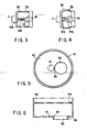
- the housing 102 is constituted by a cylinder-shaped housing main body 121 and a cap 122 that is attached to the tip end of the housing main body 121 so as to be freely detached.
- the housing main body 121 and the cap 122 are made of a material that virtually does not transmit air.
- the cap 122 which is a tube-shaped member, has a taper section 122b that narrows its inner and outer diameters toward the tip end.
- the outer edge of the tip end of the cap 122 is formed into a shape that is suitable for stimulating the periphery of the portion to be stuck and for alleviating pain at the time of sticking when it is pressed onto the surface of a living body (the skin).
- the shape is also suitable for preventing air from flowing into the housing 102 between the cap 122 and the surface of a living body when the housing 102 is in a reduced-pressure state.
- the cap 122 is preferably made of a transparent or translucent material.
- An opening 124 through which the suction plunger 105 is inserted is formed at the base end of the housing main body 121.
- side holes 125 and 126 which respectively correspond to a sticking- and suction-use operation button 184 and an air-releasing-use operation button 186 that will be described later, are formed in the side wall of the housing main body 121.
- a partition plate 127 is placed inside the housing main body 121.
- the partition plate 127 is fixedly secured to the side wall of the housing main body 121, or is integrally formed therewith.
- a guide groove 128 is formed in the side-wall inner surface of the housing main body 121 in the length direction of the housing main body 121.
- a stopper 129 with which a protruding portion 134 comes into contact is formed at the tip end of the guide groove 128 (see FIG. 9 ).
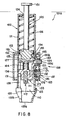
- the sticking plunger 103 is constituted by a needle holder (lancet holder) 131 to which the lancet 111 having the sticking needle 112 is detachably attached, an elastic member 132 that is integrally formed with the needle holder 131 with a first engaging section 133 provided at its end (on the base-end side), and a protruding portion 134 that is integrally formed with the needle holder 131.
- the protruding portion 134 is inserted into the guide groove 128, and allowed to slide in the length directions of the guide groove 128.
- the sticking plunger 103 is shifted inside the housing 102.
- the protruding portion 134 comes into contact with the stopper 129, thereby restricting the sticking plunger 103 in its shift toward the tip end.
- the coil spring 104 is properly set so as to have an appropriate elastic coefficient (spring constant) so as not to again stick the surface of a living body during its damping movements after the sticking needle 112 has stuck the surface of the living body.
- a suction mechanism (negative-pressure generation mechanism), which is constituted by the suction plunger 105 and the coil spring 106 for pressing the suction plunger 105 toward the base end, is installed in the housing main body 121.
- the suction plunger 105 is a rod-shaped member, and provided with a handling section 151 on its base end and a gasket 152 on its tip end.
- the gasket 152 has a seal ring (sealing member) 153 made of an elastic material along its peripheral portion.
- the seal ring 153 contacts the inner circumferential face of the housing main body 121 in an air-sealed state, and when the suction plunger 105 is shifted in a length direction of the housing main body 121, the seal ring 153 also shifts in the same direction along the inner circumferential face of the housing main body 121 in an air-sealed state.
- the seal ring 153 is preferably set to exhibit a sliding resistance to a degree not to disturb the expansion and shrinkage of the coil spring 106.
- An elastic member 154 which is elastically deformable, is formed on the side face of the gasket 152 in a protruding manner, and a second engaging section 155 is formed on its tip end.
- the second engaging section 155 is pressed to the right in FIG. 8 by the elastic force of the elastic member 154, and is engaged by the edge of the side hole 125; thus, the suction plunger 105 is restricted in its shift toward the base end.
- the respective ends of the coil spring 106 are fixed to the base end of the housing main body 121 and the gasket 152.
- the coil spring 106 is in an extended state so that the suction plunger 105 is pressed toward the base end by its elastic force.
- the air-releasing valve.107 is constituted by a disc-shaped valve member 171 that is connected to or integrally formed with the shaft 186a of the operation button 186, an elastic member 172 which has a C-letter shape (a shape of a ring with a cut-out in its one portion) and presses the operation button 186 and the valve member 171 to the right in FIG. 1 , and a ring-shaped seal pad (seal member) 173 which is secured to the valve member 171 and made of an elastic material.
- the constituent material of the elastic member 172 for example, the following materials are listed: various rubber materials, such as natural rubber, isoprene rubber, butadiene rubber, styrene-butadiene rubber, nitril rubber, chloroprene rubber, butyl rubber, acrylic rubber, ethylene-propylene rubber, hydrine rubber, urethane rubber, silicone rubber and fluorine-containing rubber, and various elastmers, such as styrene, polyolefin, polyvinyl-chloride, polyurethane, polyester, polyamide, polybutadiene and fluorinated elastmers. Further, various springs such as coil springs may be used as the elastic member 172.
- various rubber materials such as natural rubber, isoprene rubber, butadiene rubber, styrene-butadiene rubber, nitril rubber, chloroprene rubber, butyl rubber, acrylic rubber, ethylene-propylene rubber, hydrine rubber, urethan
- the operation means 108 carries out the following operations: (1) a sticking operation which is made by the sticking needle 112 on the surface of a living body through the operation of the sticking plunger 103; (2) a pressure-reducing operation applied to the space 110 by the operation of the suction plunger 105; and (3) a releasing operation applied to the space 110 so as to release the reduced-pressure state to the atmospheric pressure.
- It is constituted by a cover (case) 181 for housing the housing main body 121, the sticking- and suction-use operation button 184, the pressing member 185 and the air-releasing operation button 186.
- the pressing member 185 placed on the backside of the operation button 184, is constituted by a plate-shape member made of an elastic material such as a rubber material, and is fixedly bonded from the outside of the housing 121 in a manner so as to seal the side hole 125 in an air-sealed manner. Therefore, the pressing member 185 also has a function as a sealing member.
- first protruding portion 185a Inside the pressing member 185 are formed a first protruding portion 185a and a second protruding portion 185b that protrude toward the inside of the side hole 125.
- the first protruding portion 185a contacts the first engaging section 133, and the second protruding portion 185b contacts the second engaging section 155.
- the height (the length of protrusion) of the first protruding portion 185a is set to be greater than the height (the length of protrusion) of the second protruding portion 185b.
- the pressing direction of the operation button 184 that is, the operation direction in which the sticking plunger 103 is operated and allowed to stick
- the shifting direction (the sticking direction) of the sticking plunger 103 are set in different directions (directions virtually orthogonal to each other). This makes it possible to alleviate fear of the sticking operation, and also to keep unchanged the contact pressure of the tip end of the cap 122 onto the surface of a living body applied by the pressing force of the operation button 184, thereby ensuring a predetermined depth of the sticking operation.
- the coil spring 104 is returned to its original length through damping movements, the sticking needle 112 is pulled out of the surface of the living body and stored in the housing 102 (see FIG. 10 ).
- the sticking needle 112 is designed so as not to protrude from the tip opening 122a of the cap 122 except the sticking operation; thus, it is possible to avoid the possibility of erroneously hurting the skin, etc., and also to prevent contagion, ensuring a highly safety device.
- the coil spring which has been in an extended state is allowed to shrink by its elastic force, thereby allowing the suction plunger 105 to slide toward the base end.
- the space 110 inside the housing 102 is increased in its volume, and gradually reduced in its pressure so that blood is sucked out through the portion that has been stuck.
- bleeding is further accelerated; thus, it becomes possible to ensure to suck an amount of blood required in a short time.
- the portion of the outer air flow is considerably apart from the blood on the portion that has been stuck, and the flow of the outer air is not so rapid; therefore, no scattering occurs in the blood on the portion that has been stuck.
- FIGS. 14 through 17 are cross-sectional side views that respectively show another embodiment of the sticking tool
- FIGS. 18 through 21 are cross-sectional views that respectively show a structural example of an air-releasing means.
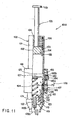
- the air-releasing valve (air-releasing means) 109 is installed in the suction plunger 105.
- the air-releasing valve 109 is constituted by an operation member 191 having an inverted letter C-shape when viewed from the top, a seal member 192 secured to one end of the operation member 191 and a tube body 193 having a vent inlet 193d.
- a head portion 191 a is attached to the other end of the operation member 191, and a slanting slope 191 b is formed in the head portion 191 a.
- the seal member 192 is made of an elastic material as described earlier, and a vent path 192a having a narrow-diameter section is formed in the center thereof. As illustrated in FIG. 18 , the upper end of the vent path 192a communicates with an inner space 156 formed in the suction plunger 105 on the base-end side from the flange 157.
- a fitting section 192b is formed in the seal member 192, and the fitting section 192b is fitted to one end of the operation member 191 and fixedly bonded thereto.
- any of hard materials such as a hard resin and a metal material, soft materials such as a soft resin and elastic materials as described earlier, may be applied; however, it is preferable to use hard or soft resin materials.
- the inner spaces 156 at the respective ends of the air-releasing valve 109 are allowed to communicate with each other through the vent path 193a, the vent opening 193d and the inside of the tube body 193 so that air flow is available.
- the air-releasing valve 109 is opened in a reduced-pressure state of the space 110, air flows into the space 110 through paths indicated by arrows in FIG. 20 .
- the air-releasing valve 109 also serves as a relief valve which, upon having a pressurized state in the space 110 due to the shifting operation of the suction plunger 105 toward the tip end, releases air corresponding to the excessive pressure.
- the air-releasing valve 109 being closed (a state shown in FIG. 18 and FIG. 19 )
- the air inside the space 110 is externally released through the fine flow-path 193e of the tube body 193 little by little.
- a slanting face (cam face) 121 a which engages the slanting face 191 b of the head section 191 a, is formed in the inner face on the base-end side of the housing main body 121.
- a step-gap section 121 b is formed in the inner face on the base-end side of the housing main body 121, which is the side opposite to the slanting face 121 a.
- the step-gap section 121 b engages the outer circumferential portion on the base-end side of the gasket 152 so as to restrict the shift of the suction plunger 105 toward the base end.
- the opening of the air-releasing valve 109 which is made when the slanting face 191 b passes through the slanting face 121 a, takes place immediately before the gasket 152 is engaged by the step-gap section 121 b, that is, immediately before the suction plunger 105 has arrived at the limit position of shift on the base-end side.
- the time that is taken from the release of the engaging section 155 from the edge of the side hole 125 to the opening of the air-releasing valve 109 is set as a time period that sufficiently allows an amount of blood required to be sucked through the portion that has been stuck by the sticking needle 112; and, for example, this is preferably set in the range of 3 to 10 seconds.
- This time can be set appropriately by selecting factors, such as the spring elasticity of the coil spring 106, the sliding resistance of the seal ring 153 against the inner face of the housing main body 121, the shift stroke of the suction plunger 105 and the installation position of the slanting face 121a.
- the time can also be adjusted by exchanging the coil spring 106 and/or the seal ring 153.
- a stopper 129a with which the tip face of the needle holder 131 comes into contact is formed in the inner face of the tip end of the housing main body 121.
- the stopper 129a is secured to the inner surface of the housing main body 121, for example, by means of threads, and can be adjusted in its position in the length direction with respect to the housing main body 121 by the amount of revolutions of the threads. In this manner, the amount of protrusion of the sticking needle 112, that is, the depth of sticking into the surface of a living body, can be adjusted depending on individual differences in the person whose blood is to be sampled (the subject) and differences in the portion to be stuck.
- the gear structure of a micrometer may be adopted.
- the suction plunger 105 is shifted toward the tip end by pressing the handling section 151 of the suction plunger 105, the second engaging section 155 is again engaged by the edge of the side hole 125, and the tip end of the cap 122 is pressed onto the surface of the living body with the space 110 being in an air-sealed state in the same manner as described earlier; thereafter, the operation button 184 is pressed, thereby releasing the engagement of the second engaging section 155 so that the space 110 is brought to a reduced-pressure state so as to suck blood through the portion that has been stuck, and the pressure of the space 110 is automatically returned to the atmospheric pressure.
- the suction plunger 105 when the suction plunger 105 is pressed and shifted toward the tip end with the tip end of the cap 122 being pressed onto the surface of a living body, the pressure in the space 110 is raised from the atmospheric pressure, making a pressurized state in the space 110, since the space 110 is tightly sealed.
- the air-releasing valve 109 also serves as a relief valve as described earlier, air corresponding to the excessive pressure is externally released through the fine flow-path 193e of the tube body 193.
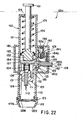
- FIGS. 22 through 25 are cross-sectional side views that respectively show another embodiment of a sticking tool.
- sticking tool 101C shown in these drawings based upon distinctions from the above-mentioned sticking tool 101 A, and with respect to the same operations, the description thereof is omitted.
- base end the upper side
- tip end the lower side
- a lever 184a is attached to the operation button 184 in a manner so as to stick in a direction orthogonal to the shifting direction of the operation button 184.
- the mechanism for releasing the inside of the housing so as to return the pressure to the atmospheric pressure after the suction process is provided; therefore, it is possible to prevent scattering of the body fluids due to a rapid air flow occurring in the proximity of the portion that has been stuck.
- an air-releasing operation is carried out without the need for the shift of the sticking needle (coming close to the surface of a living body), it is possible to prevent an erroneous sticking recurring on the surface of the living body, and consequently to provide a highly safe device.
- the sticking operation and the suction operation are carried out in this order or at the same time, and the air-releasing operation is then carried out successively.
- the depth of sticking can be appropriately adjusted depending on various conditions, such as individual differences and differences in the portion to be stuck, and every time a body-fluid sampling (blood sampling) operation is performed, a constant depth of sticking is provided.
- preparation operations prior to use that is, operations for setting the sticking plunger and suction plunger in an operative state, are simple and easy; this is advantageous when the device is used regularly or repeatedly.
- the sticking needle is designed not to protrude from the tip opening except for the sticking operation, it is possible to prevent accidents such as an erroneous sticking; this ensures a highly safe device.
- the sticking needle is not directly visible, it is possible to alleviate fear of sticking.
- the sticking tool has a simple structure and is suitable for mass production.
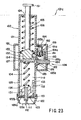
- a sticking tool 201 whose cross-section is shown in FIG. 26 is mainly used for sampling a fine amount of body fluids, such as blood, from the surface of a living body.
- the sticking tool 201 is constituted by a housing 202, a plunger 203 which slides inside the housing 202, a lancet 204 which is attached to the tip end of the plunger 203 and has a sticking needle 241 that extends toward the tip end, a stopper 205 connected to the rear end of the plunger 203, an adjusting mechanism 210 that contacts the stopper 205, and a sticking-use spring 206 used for shifting the plunger 203, the lancet 204 and the stopper 205 toward the tip.
- An engaging section 8 is installed on the inner face of the housing 202, and a stopping section 207, which engages the engaging section 208 so as to stop the plunger 203, the lancet 204 and the stopper 205 at a first position, is installed in the plunger 203.
- the shape of the housing 202 is not particularly limited as long as it has a cylindrical shape as shown in FIG. 26 ; however, from the viewpoint of ease of gripping, it is preferable to provide it as a cylinder. Moreover, it is more preferable to provide a flat section 221 shown in a plan view of FIG. 29 on the periphery of the engaging section 208, because the engagement between the stopping section 207 and the engaging section 208 can be easily released without the need for observing it, merely by sliding the finger along the flat section 221.
- the sticking-use spring 206 one end of which is connected to the plunger 203 and the other end of which is connected to a sticking-use spring fixing base 209 installed inside the housing, is inserted in a compressed state.
- the present invention is not intended to be limited to this structure, and one end may be connected to the lancet 204 or the stopper 205, while the other end may be directly connected to the inner face of the housing 202.
- the engaging section 208 is not particularly limited as long as it engages the stopping section 207 installed on the inner face of the housing 202; however, it is preferable to provide it as a hole penetrating the housing 202 from the inner face to the outer face as is shown in the present embodiment. With this structure, it is possible to ensure the engagement with the stopping section 207, and also to easily release the engagement by pushing the stopping section 207.
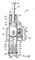
- the stopper 205 is connected to the rear end of the plunger 203 and provided with a stopper-side shift restriction mechanism 251.
- the stopper-side shift restriction mechanism 251 engages an adjustment-mechanism-side shift restriction mechanism 210a so that the plunger 203, the lancet 204 and the stopper 205, which have shifted from the first position, are stopped at the second position.
- a shock which is transmitted to the lancet when the plunger 203, the lancet 204 and the stopper 205 have been stopped at the second position from the first position, can be damped by the stopper 205.
- the shock is not directly transmitted to the lancet; therefore, it is possible to prevent an accidental separation of the sticking tool 1 from the hand of the operator by the shock, trembling of the sticking operation and unnecessary pain being given to the person whose body fluids are sampled.
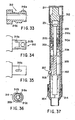
- the adjustment mechanism 210 has a structure whose front view is shown in FIG. 30 and whose plan view is shown in FIG. 31 . Specifically, a helical groove 210d is formed on the peripheral portion thereof. This groove 210d allows a protruding member 212b installed in a connecting section which will be described later to relatively move along the inside thereof.
- the adjustment mechanism 210 extends in the rear-end direction from the sticking-use spring fixing base 209 installed on the inner face of the housing 202, and is fitted to the connecting section 212 which has a cylinder shape so as to allow the stopper 205 to slide therein.
- the shift range of the stopper 205, etc. from the first position to the second position is indicated by the position of the adjustment mechanism 210 in the length direction and distance X (see FIG. 26 ) from plane A (see FIG. 26 ) of the stopper-side shift restriction mechanism 51 and plane B (see FIG. 26 ) of the adjustment-mechanism-side shift restriction mechanism 210a.
- FIG. 37 shows a state in which the shift range from the first position to the second position is small
- FIG. 38 shows a state in which the shift range from the first position to the second position is large.
- the position of the adjustment mechanism 210 in the length direction is determined by the position of the protruding member 212b of the connecting section 212 inside the helical groove 210d of the adjustment mechanism 210, which is given by axially rotating the adjustment mechanism 210.
- distance X is adjusted and determined by axially rotating the adjustment mechanism 210.
- distance X can be adjusted not at equal intervals, but at predetermined values such as 0.1 mm, 0.2 mm, 0.3 mm and 0.4 mm.
- a mark 210f on the uninserted portion 210b so as to allow visual confirmation of a set value that is to be adjusted by the adjustment mechanism 210.
- the connecting section 212 is preferably provided with one or two or more slits 212a that extend in the length direction.
- the installation of the slits 212a makes it possible to accept a distortion that occurs inside the adjustment mechanism 210 when the stopper-side shift restriction mechanism 251 and the adjustment-mechanism-side shift restriction mechanism 210a come into contact with each other.
- the connecting section 212 is not necessarily provided, and another structure may be provided in which a protruding member corresponding to the protruding member 212b is attached to either one of the inner face of the housing 202 and the outer face of the adjustment mechanism 210 and a helical groove corresponding to the helical groove 210d is formed in the other so that the position of the adjustment mechanism 210 is adjusted by axially rotating the adjustment mechanism.
- a cap 214 on the tip end of the housing 202.
- the installation method of the cap 214 and the housing 202 is not particularly limited, and a snap-in method and a screwing method by using threads are listed so as to allow easy removal.
- an opening 214a is formed in the contact face to the surface of a living body of the cap 214, and its diameter is set in the range of not less than 1 mm to not more than 10 mm, and more preferably in the range of not less than 1 mm to not more than 6 mm, so as to carry out the sticking operation without limiting the portion to be stuck.
- the cap may have another structure as indicated by a cap 214b whose cross-sectional view of the tip portion is shown in FIG. 39 .
- the cap 214b houses a lancet 204b which can slide inside thereof and to which a sticking needle 241 b is connected.
- the cap 214b makes it possible to connect the other end of the lancet 204 to the plunger 203 when the cap 214b is connected to the housing 202b; thus, the same application as described in an explanation of the application of the present embodiment that will be given later is available.
- the plunger 203 it is preferable to respectively provide an axial direction groove 222 in the inner face of the housing 202 and a tremble-preventing protrusion 231 on the plunger 203.
- the tremble-preventing protrusion 231 shifts along the axial direction groove 222 so that the plunger 203 is allowed to move only in the axial direction in a stable manner without trembling in the axial rotation direction; therefore, this allows the sticking needle 241 to stick at an accurate position.
- the materials of the above-mentioned constituent parts are not particularly limited, and they are appropriately selected from hard plastics, metals, etc.
- a material such as a thermoplastic elastomer and rubber, which can maintain the sliding face in an air-sealed state.
- a suction means may be preliminarily provided so that the space inside the housing 202, formed by the plunger 203 and the tip end sealed by the surface of a living body, is brought to a reduced-pressure state, thereby making the surface of the living body swell into the housing 202. Then, the swelled surface may be stuck with the sticking needle 241 so as to effectively suck body fluids to be sampled.
- the operator removes the protection cover 211, and sets the second position of the plunger 203, the lancet 204 and the stopper 205 which allows to suck a minimum amount of body fluids such as blood required for an inspection, that is, the shift distance of the sticking needle 241.
- a minimum amount of body fluids such as blood required for an inspection
- the adjustment mechanism 210 it is not necessary to frequently reset the setting; therefore, the use of the protection cover 11 makes it possible to prevent the sticking needle from being stuck deeper due to an erroneous change in the depth of sticking, erroneous blood sampling, and other misoperations.
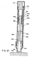
- the lancet 204 having the sticking needle 241 is attached to the tip end of the plunger 203, and the plunger 203 with the lancet 204 attached thereto is pushed toward the rear end against the elastic force of the sticking-use spring 206 so that the stopping section 207 is engaged by the edge of the engaging section 208.
- the sticking-use spring 206 is maintained in a compressed state.
- the opening 214a of the tip end of the cap 214 is pressed onto the surface of a living body such as the finger tip, and the stopping section 207 protruding from the engaging section 208 is pressed.
- the stopper 205 slides inside the housing 202 together with the plunger 203, the stopper-side shift restriction mechanism 251 of the stopper 205 comes into contact with the adjustment-mechanism-side shift restriction mechanism 210a of the adjustment mechanism 210 so that the shift of the plunger 203 toward the tip end is restricted; thus, the depth of sticking by the sticking needle 241 of the lancet 204 onto the surface of a living body is adjusted to a predetermined depth.
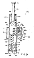
- the sticking-use spring 208 returns to its natural length through damping movements, and the sticking needle is drawn from the surface of the living body and stored in the housing 202 (see FIG. 28 ).
- the sticking tool 201 is designed so that the lancet 204 does not protrude from the opening 214a of the tip end of the cap 214 except that it is used for the sticking operation; therefore, it is possible to prevent the sticking needle from erroneously hurt the skin, etc., to prevent contagion, etc., and also to provide a highly safe device.
- the sticking operation can be performed onto the predetermined sticking position with high reproducibility.
- the sticking tool of the present invention is provided with the mechanism for adjusting the depth of sticking by the lancet; this allows the operator to set the depth of sticking suitable for obtaining a minimum amount of blood required for an inspection, and makes it possible to reduce a pain accompanying the sticking operation to a minimum level required.
Landscapes
- Health & Medical Sciences (AREA)
- Life Sciences & Earth Sciences (AREA)
- Engineering & Computer Science (AREA)
- Molecular Biology (AREA)
- Hematology (AREA)
- Biomedical Technology (AREA)
- Physics & Mathematics (AREA)
- General Health & Medical Sciences (AREA)
- Pathology (AREA)
- Heart & Thoracic Surgery (AREA)
- Medical Informatics (AREA)
- Surgery (AREA)
- Animal Behavior & Ethology (AREA)
- Biophysics (AREA)
- Public Health (AREA)
- Veterinary Medicine (AREA)
- Dermatology (AREA)
- Pain & Pain Management (AREA)
- Immunology (AREA)
- Urology & Nephrology (AREA)
- Chemical & Material Sciences (AREA)
- Cell Biology (AREA)
- Microbiology (AREA)
- Biotechnology (AREA)
- Food Science & Technology (AREA)
- Medicinal Chemistry (AREA)
- Analytical Chemistry (AREA)
- Biochemistry (AREA)
- General Physics & Mathematics (AREA)
- Measurement Of The Respiration, Hearing Ability, Form, And Blood Characteristics Of Living Organisms (AREA)
- Measuring And Recording Apparatus For Diagnosis (AREA)
- Sampling And Sample Adjustment (AREA)
Claims (2)
- Einstechinstrument (201) zum Einstechen in eine Oberfläche eines Körpers, umfassend:- ein Gehäuse (202) mit einem vorderen Ende, welches offen ist;- einen Kolben (203), an dem eine Lanzette (204) mit einer Einstechnadel (241), die sich zum vorderen Ende hin erstreckt, befestigt ist, wobei sich der Kolben (203) im Inneren des Gehäuses (202) bewegen kann,- einen Stopper (205), der in Richtung des hinteren Endes des Kolbens (203) verbunden ist, und- eine dem Einstechen dienende Feder (206) zum Schieben der Lanzette (204), des Kolbens (203) und des Stoppers (205) in Richtung des vorderen Endes des Gehäuses (202), wobei die dem Einstechen dienende Feder (206) mit dem Kolben (203) oder mit dem Stopper (205) verbunden ist,
wobei: die Lanzette (204) so in einer Kappe (214) untergebracht ist, dass sie in einer axialen Längsrichtung verschoben werden kann, wobei die Kappe (214) die Einstechnadel (241) abdeckt und mit dem vorderen Ende des Gehäuses (202) verbunden werden kann, und, wenn die Kappe (214) mit dem vorderen Ende des Gehäuses (202) verbunden ist, die Lanzette (204) mit dem Kolben (203) in einem Zustand verbunden ist, in dem sie sich in der Kappe (214) befindet,- ein Eingriffsabschnitt (208) in der Innenfläche des Gehäuses (202) vorgesehen ist,- ein Stoppabschnitt (207) in wenigstens einem von der Lanzette (204), dem Kolben (203) und dem Stopper (205) ausgebildet ist,
dadurch gekennzeichnet, dass
das Einstechinstrument (201) ferner einen Verbindungsabschnitt (212), der an dem Gehäuse (202) befestigt ist und sich in der axialen Richtung innerhalb des Gehäuses (202) erstreckt, einen Einstellmechanismus (210), der den Stopper (205) berührt und in einer Weise ausgebildet ist, dass er den Verbindungsabschnitt (212) abdeckt, eine in wenigstens einem von dem Einstellmechanismus (210) und dem Verbindungsabschnitt (212) vorgesehene schraubenförmige Nut und einen auf dem anderen so ausgebildeten Vorsprung (212b) umfasst, dass er sich entlang der schraubenförmigen Nut (210d) verschiebt, und dass eine zweite Position durch axiales Drehen des auf einer Längsachse im Inneren des Gehäuses (202) zentrierten Einstellmechanismus (210) unter Verwendung des Vorsprungs (212b), der sich entlang der Nut verschiebt, eingestellt wird, und dass
der Stoppabschnitt (207) den Eingriffsabschnitt (208) belegen kann, um die Lanzette (204), den Kolben (203) und den Stopper (205) in einer ersten Position anzuhalten, und dass nach dem Verschieben der Lanzette (204), des Kolbens (203) und des Stoppelementes (205) in Richtung des vorderen Endes aus der ersten Position durch die Feder (206), die aus dem Eingriff zwischen dem Eingriffsabschnitt (208) und dem Anschlagabschnitt (207) gelöst wurde, der Stopper (205) mit dem Einstellmechanismus in Kontakt kommt, so dass die Verschiebung der Lanzette (204), des Kolbens (203) und des Stoppers (205) in einer zweiten Position angehalten wird. - Einstechinstrument (201) nach Anspruch 1, dadurch gekennzeichnet, dass zumindest nicht weniger als ein Befestigungsmittel (212c) in dem Einstellmechanismus (210) und dem Gehäuse (202) vorgesehen ist, wobei das Befestigungsmittel den Einstellmechanismus (210) in einer vorgegebenen zweiten Position anhalten kann, wenn die zweite Position durch axiales Drehen des auf einer Längsachse zentrierten Einstellmechanismus (210) eingestellt ist.
Applications Claiming Priority (7)
| Application Number | Priority Date | Filing Date | Title |
|---|---|---|---|
| JP10025091A JPH11206742A (ja) | 1998-01-22 | 1998-01-22 | 穿刺具 |
| JP2509198 | 1998-01-22 | ||
| JP18379498 | 1998-06-30 | ||
| JP10183794A JP2000014662A (ja) | 1998-01-22 | 1998-06-30 | 体液検査装置 |
| JP29632598 | 1998-10-19 | ||
| JP29632598A JP3902875B2 (ja) | 1998-10-19 | 1998-10-19 | 穿刺器具 |
| EP99400147A EP0931507B1 (de) | 1998-01-22 | 1999-01-22 | Vorrichtung zur Untersuchung von Körperflüssigkeit |
Related Parent Applications (2)
| Application Number | Title | Priority Date | Filing Date |
|---|---|---|---|
| EP99400147A Division EP0931507B1 (de) | 1998-01-22 | 1999-01-22 | Vorrichtung zur Untersuchung von Körperflüssigkeit |
| EP99400147.7 Division | 1999-01-22 |
Publications (3)
| Publication Number | Publication Date |
|---|---|
| EP1609417A2 EP1609417A2 (de) | 2005-12-28 |
| EP1609417A3 EP1609417A3 (de) | 2014-06-25 |
| EP1609417B1 true EP1609417B1 (de) | 2015-09-02 |
Family
ID=27284890
Family Applications (3)
| Application Number | Title | Priority Date | Filing Date |
|---|---|---|---|
| EP99400147A Expired - Lifetime EP0931507B1 (de) | 1998-01-22 | 1999-01-22 | Vorrichtung zur Untersuchung von Körperflüssigkeit |
| EP05020687.9A Expired - Lifetime EP1609417B1 (de) | 1998-01-22 | 1999-01-22 | Stechhilfevorrichtung mit Tiefenverstellung |
| EP05020686.1A Withdrawn EP1609416A3 (de) | 1998-01-22 | 1999-01-22 | Vorrichtung zur Untersuchung von Körperflüssigkeit |
Family Applications Before (1)
| Application Number | Title | Priority Date | Filing Date |
|---|---|---|---|
| EP99400147A Expired - Lifetime EP0931507B1 (de) | 1998-01-22 | 1999-01-22 | Vorrichtung zur Untersuchung von Körperflüssigkeit |
Family Applications After (1)
| Application Number | Title | Priority Date | Filing Date |
|---|---|---|---|
| EP05020686.1A Withdrawn EP1609416A3 (de) | 1998-01-22 | 1999-01-22 | Vorrichtung zur Untersuchung von Körperflüssigkeit |
Country Status (8)
| Country | Link |
|---|---|
| US (1) | US6261245B1 (de) |
| EP (3) | EP0931507B1 (de) |
| JP (1) | JP2000014662A (de) |
| KR (1) | KR100301308B1 (de) |
| CN (1) | CN1167382C (de) |
| DE (1) | DE69932191T2 (de) |
| SG (1) | SG89273A1 (de) |
| TW (1) | TW376309B (de) |
Families Citing this family (158)
| Publication number | Priority date | Publication date | Assignee | Title |
|---|---|---|---|---|
| US7828749B2 (en) | 1996-05-17 | 2010-11-09 | Roche Diagnostics Operations, Inc. | Blood and interstitial fluid sampling device |
| US20020010406A1 (en) | 1996-05-17 | 2002-01-24 | Douglas Joel S. | Methods and apparatus for expressing body fluid from an incision |
| US7235056B2 (en) | 1996-05-17 | 2007-06-26 | Amira Medical | Body fluid sampling device and methods of use |
| US7666150B2 (en) | 1996-05-17 | 2010-02-23 | Roche Diagnostics Operations, Inc. | Blood and interstitial fluid sampling device |
| EP1579814A3 (de) | 1996-05-17 | 2006-06-14 | Roche Diagnostics Operations, Inc. | Verfahren und Vorrichtung zur Probenahme und Analyse von Körperflüssigkeit |
| US6036924A (en) | 1997-12-04 | 2000-03-14 | Hewlett-Packard Company | Cassette of lancet cartridges for sampling blood |
| US6391005B1 (en) | 1998-03-30 | 2002-05-21 | Agilent Technologies, Inc. | Apparatus and method for penetration with shaft having a sensor for sensing penetration depth |
| US6187000B1 (en) * | 1998-08-20 | 2001-02-13 | Endius Incorporated | Cannula for receiving surgical instruments |
| US6591125B1 (en) | 2000-06-27 | 2003-07-08 | Therasense, Inc. | Small volume in vitro analyte sensor with diffusible or non-leachable redox mediator |
| DE10010694A1 (de) * | 2000-03-04 | 2001-09-06 | Roche Diagnostics Gmbh | Blutlanzette mit hygienischen Spitzenschutz |
| WO2003026506A1 (en) | 2001-09-19 | 2003-04-03 | Terumo Kabushiki Kaisha | Apparatus for measuring component and chip |
| US7780610B2 (en) * | 2000-05-01 | 2010-08-24 | Terumo Kabushiki Kaisha | Component measuring instrument and chip |
| DE60135692D1 (de) * | 2000-07-26 | 2008-10-16 | Terumo Corp | Kombination aus einer Vorrichtung und einem Chip zum Messen von Körperflüssigkeitsbestandteilen |
| JP4493172B2 (ja) * | 2000-07-26 | 2010-06-30 | テルモ株式会社 | 成分測定装置 |
| JP4493181B2 (ja) * | 2000-08-18 | 2010-06-30 | テルモ株式会社 | 成分測定装置 |
| JP4493180B2 (ja) * | 2000-08-18 | 2010-06-30 | テルモ株式会社 | 成分測定装置 |
| US20020137999A1 (en) * | 2000-08-11 | 2002-09-26 | Bandeian John J. | Medical alarm system |
| JP4536890B2 (ja) * | 2000-09-12 | 2010-09-01 | テルモ株式会社 | 成分測定装置用チップおよび成分測定システム |
| DE10053974A1 (de) | 2000-10-31 | 2002-05-29 | Roche Diagnostics Gmbh | System zur Blutentnahme |
| US8641644B2 (en) | 2000-11-21 | 2014-02-04 | Sanofi-Aventis Deutschland Gmbh | Blood testing apparatus having a rotatable cartridge with multiple lancing elements and testing means |
| US7691071B2 (en) | 2001-01-19 | 2010-04-06 | Panasonic Corporation | Lancet-integrated sensor, measurer for lancet-integrated sensor, and cartridge |
| US6866675B2 (en) | 2001-01-22 | 2005-03-15 | Roche Diagnostics Operations, Inc. | Lancet device having capillary action |
| KR100893275B1 (ko) * | 2001-03-29 | 2009-04-17 | 라이프스캔 스코트랜드 리미티드 | 일체식 샘플 시험용 계측기 |
| US20020188223A1 (en) | 2001-06-08 | 2002-12-12 | Edward Perez | Devices and methods for the expression of bodily fluids from an incision |
| DE60213822T2 (de) | 2001-06-08 | 2007-08-02 | Roche Diagnostics Gmbh | Entnahmevorrichtung für körperflüssigkeiten und testmedienskassette |
| EP1404232B1 (de) | 2001-06-12 | 2009-12-02 | Pelikan Technologies Inc. | Gerät und verfahren zur entnahme von blutproben |
| US8337419B2 (en) | 2002-04-19 | 2012-12-25 | Sanofi-Aventis Deutschland Gmbh | Tissue penetration device |
| JP4149911B2 (ja) | 2001-06-12 | 2008-09-17 | ペリカン テクノロジーズ インコーポレイテッド | 電気式ランセットアクチュエータ |
| WO2002100461A2 (en) | 2001-06-12 | 2002-12-19 | Pelikan Technologies, Inc. | Method and apparatus for improving success rate of blood yield from a fingerstick |
| US7981056B2 (en) | 2002-04-19 | 2011-07-19 | Pelikan Technologies, Inc. | Methods and apparatus for lancet actuation |
| US7041068B2 (en) | 2001-06-12 | 2006-05-09 | Pelikan Technologies, Inc. | Sampling module device and method |
| JP4209767B2 (ja) * | 2001-06-12 | 2009-01-14 | ペリカン テクノロジーズ インコーポレイテッド | 皮膚の性状の一時的変化に対する適応手段を備えた自動最適化形切開器具 |
| AU2002315179A1 (en) * | 2001-06-12 | 2002-12-23 | Pelikan Technologies, Inc. | Blood sampling device with diaphragm actuated lancet |
| US9795747B2 (en) | 2010-06-02 | 2017-10-24 | Sanofi-Aventis Deutschland Gmbh | Methods and apparatus for lancet actuation |
| US9226699B2 (en) | 2002-04-19 | 2016-01-05 | Sanofi-Aventis Deutschland Gmbh | Body fluid sampling module with a continuous compression tissue interface surface |
| US9427532B2 (en) | 2001-06-12 | 2016-08-30 | Sanofi-Aventis Deutschland Gmbh | Tissue penetration device |
| WO2002100254A2 (en) | 2001-06-12 | 2002-12-19 | Pelikan Technologies, Inc. | Method and apparatus for lancet launching device integrated onto a blood-sampling cartridge |
| US7344507B2 (en) | 2002-04-19 | 2008-03-18 | Pelikan Technologies, Inc. | Method and apparatus for lancet actuation |
| DE10142232B4 (de) | 2001-08-29 | 2021-04-29 | Roche Diabetes Care Gmbh | Verfahren zur Herstellung eines analytischen Hilfsmittels mit Lanzette und Testelement |
| JP2005501591A (ja) | 2001-08-29 | 2005-01-20 | エフ ホフマン−ラ ロッシュ アクチェン ゲゼルシャフト | 体液をサンプリングする際に使用するための滲出方法および構造体 |
| US6645219B2 (en) | 2001-09-07 | 2003-11-11 | Amira Medical | Rotatable penetration depth adjusting arrangement |
| JP4320255B2 (ja) * | 2001-09-26 | 2009-08-26 | エフ ホフマン−ラ ロッシュ アクチェン ゲゼルシャフト | 体液を採取するための携帯型器具 |
| US20040098010A1 (en) * | 2001-10-22 | 2004-05-20 | Glenn Davison | Confuser crown skin pricker |
| JP4299667B2 (ja) * | 2001-10-31 | 2009-07-22 | アークレイ株式会社 | 穿刺装置 |
| US6659966B2 (en) * | 2001-11-15 | 2003-12-09 | Roche Diagnostics Corporation | Fluid sampling apparatus |
| AU2002359620A1 (en) * | 2001-12-07 | 2003-06-23 | Micronix, Inc. | Consolidated body fluid testing device and method |
| US7297122B2 (en) | 2002-04-19 | 2007-11-20 | Pelikan Technologies, Inc. | Method and apparatus for penetrating tissue |
| US7374544B2 (en) | 2002-04-19 | 2008-05-20 | Pelikan Technologies, Inc. | Method and apparatus for penetrating tissue |
| US8221334B2 (en) | 2002-04-19 | 2012-07-17 | Sanofi-Aventis Deutschland Gmbh | Method and apparatus for penetrating tissue |
| US7331931B2 (en) | 2002-04-19 | 2008-02-19 | Pelikan Technologies, Inc. | Method and apparatus for penetrating tissue |
| US7485128B2 (en) | 2002-04-19 | 2009-02-03 | Pelikan Technologies, Inc. | Method and apparatus for penetrating tissue |
| US7909778B2 (en) | 2002-04-19 | 2011-03-22 | Pelikan Technologies, Inc. | Method and apparatus for penetrating tissue |
| US7582099B2 (en) | 2002-04-19 | 2009-09-01 | Pelikan Technologies, Inc | Method and apparatus for penetrating tissue |
| US7491178B2 (en) | 2002-04-19 | 2009-02-17 | Pelikan Technologies, Inc. | Method and apparatus for penetrating tissue |
| US8784335B2 (en) | 2002-04-19 | 2014-07-22 | Sanofi-Aventis Deutschland Gmbh | Body fluid sampling device with a capacitive sensor |
| US7901362B2 (en) | 2002-04-19 | 2011-03-08 | Pelikan Technologies, Inc. | Method and apparatus for penetrating tissue |
| US8360992B2 (en) | 2002-04-19 | 2013-01-29 | Sanofi-Aventis Deutschland Gmbh | Method and apparatus for penetrating tissue |
| US7232451B2 (en) * | 2002-04-19 | 2007-06-19 | Pelikan Technologies, Inc. | Method and apparatus for penetrating tissue |
| US9248267B2 (en) | 2002-04-19 | 2016-02-02 | Sanofi-Aventis Deustchland Gmbh | Tissue penetration device |
| US8579831B2 (en) | 2002-04-19 | 2013-11-12 | Sanofi-Aventis Deutschland Gmbh | Method and apparatus for penetrating tissue |
| US7410468B2 (en) | 2002-04-19 | 2008-08-12 | Pelikan Technologies, Inc. | Method and apparatus for penetrating tissue |
| US7674232B2 (en) | 2002-04-19 | 2010-03-09 | Pelikan Technologies, Inc. | Method and apparatus for penetrating tissue |
| US9795334B2 (en) | 2002-04-19 | 2017-10-24 | Sanofi-Aventis Deutschland Gmbh | Method and apparatus for penetrating tissue |
| US7371247B2 (en) * | 2002-04-19 | 2008-05-13 | Pelikan Technologies, Inc | Method and apparatus for penetrating tissue |
| US8372016B2 (en) | 2002-04-19 | 2013-02-12 | Sanofi-Aventis Deutschland Gmbh | Method and apparatus for body fluid sampling and analyte sensing |
| US7547287B2 (en) | 2002-04-19 | 2009-06-16 | Pelikan Technologies, Inc. | Method and apparatus for penetrating tissue |
| US9314194B2 (en) | 2002-04-19 | 2016-04-19 | Sanofi-Aventis Deutschland Gmbh | Tissue penetration device |
| US7717863B2 (en) | 2002-04-19 | 2010-05-18 | Pelikan Technologies, Inc. | Method and apparatus for penetrating tissue |
| US7708701B2 (en) | 2002-04-19 | 2010-05-04 | Pelikan Technologies, Inc. | Method and apparatus for a multi-use body fluid sampling device |
| US7229458B2 (en) | 2002-04-19 | 2007-06-12 | Pelikan Technologies, Inc. | Method and apparatus for penetrating tissue |
| US7648468B2 (en) | 2002-04-19 | 2010-01-19 | Pelikon Technologies, Inc. | Method and apparatus for penetrating tissue |
| US7563232B2 (en) | 2002-04-19 | 2009-07-21 | Pelikan Technologies, Inc. | Method and apparatus for penetrating tissue |
| US7976476B2 (en) | 2002-04-19 | 2011-07-12 | Pelikan Technologies, Inc. | Device and method for variable speed lancet |
| US7291117B2 (en) | 2002-04-19 | 2007-11-06 | Pelikan Technologies, Inc. | Method and apparatus for penetrating tissue |
| US8702624B2 (en) | 2006-09-29 | 2014-04-22 | Sanofi-Aventis Deutschland Gmbh | Analyte measurement device with a single shot actuator |
| US8267870B2 (en) | 2002-04-19 | 2012-09-18 | Sanofi-Aventis Deutschland Gmbh | Method and apparatus for body fluid sampling with hybrid actuation |
| US7258693B2 (en) * | 2002-04-19 | 2007-08-21 | Pelikan Technologies, Inc. | Device and method for variable speed lancet |
| US7892183B2 (en) | 2002-04-19 | 2011-02-22 | Pelikan Technologies, Inc. | Method and apparatus for body fluid sampling and analyte sensing |
| US7244265B2 (en) | 2002-04-19 | 2007-07-17 | Pelikan Technologies, Inc. | Method and apparatus for penetrating tissue |
| DE10223558A1 (de) | 2002-05-28 | 2003-12-11 | Roche Diagnostics Gmbh | Blutentnahmesystem |
| CN100361623C (zh) * | 2002-11-01 | 2008-01-16 | 佩利坎技术公司 | 用于体液采样的方法和装置 |
| US7731900B2 (en) * | 2002-11-26 | 2010-06-08 | Roche Diagnostics Operations, Inc. | Body fluid testing device |
| US7582258B2 (en) * | 2002-12-23 | 2009-09-01 | Roche Diagnostics Operations, Inc. | Body fluid testing device |
| DK1578271T3 (da) | 2002-12-23 | 2011-09-12 | Hoffmann La Roche | Kropsfluidumtestapparat |
| US8574895B2 (en) | 2002-12-30 | 2013-11-05 | Sanofi-Aventis Deutschland Gmbh | Method and apparatus using optical techniques to measure analyte levels |
| US20040132167A1 (en) * | 2003-01-06 | 2004-07-08 | Peter Rule | Cartridge lance |
| US6983177B2 (en) | 2003-01-06 | 2006-01-03 | Optiscan Biomedical Corporation | Layered spectroscopic sample element with microporous membrane |
| AU2004200523A1 (en) * | 2003-02-19 | 2004-09-09 | Bayer Healthcare, Llc | Endcap for Lancing Device and Method of Use |
| ATE447361T1 (de) * | 2003-03-17 | 2009-11-15 | Arkray Inc | Punktionsvorrichtung |
| DE602004028463D1 (de) | 2003-05-30 | 2010-09-16 | Pelikan Technologies Inc | Verfahren und vorrichtung zur injektion von flüssigkeit |
| ES2490740T3 (es) | 2003-06-06 | 2014-09-04 | Sanofi-Aventis Deutschland Gmbh | Aparato para toma de muestras de fluido sanguíneo y detección de analitos |
| WO2006001797A1 (en) | 2004-06-14 | 2006-01-05 | Pelikan Technologies, Inc. | Low pain penetrating |
| US8282576B2 (en) | 2003-09-29 | 2012-10-09 | Sanofi-Aventis Deutschland Gmbh | Method and apparatus for an improved sample capture device |
| US9351680B2 (en) | 2003-10-14 | 2016-05-31 | Sanofi-Aventis Deutschland Gmbh | Method and apparatus for a variable user interface |
| US7179233B2 (en) * | 2003-10-31 | 2007-02-20 | Yu-Hong Chang | Compact structure of a new biosensor monitor |
| US7822454B1 (en) | 2005-01-03 | 2010-10-26 | Pelikan Technologies, Inc. | Fluid sampling device with improved analyte detecting member configuration |
| US8668656B2 (en) | 2003-12-31 | 2014-03-11 | Sanofi-Aventis Deutschland Gmbh | Method and apparatus for improving fluidic flow and sample capture |
| EP1726259B1 (de) * | 2004-03-15 | 2011-10-05 | Terumo Kabushiki Kaisha | Vorrichtung zum auffangen von körperflüssigkeiten |
| BRPI0509527A (pt) * | 2004-04-01 | 2007-09-18 | Bayer Healthcare Llc | ponteira para dispositivo de lancetagem a vácuo |
| GB0409354D0 (en) * | 2004-04-27 | 2004-06-02 | Owen Mumford Ltd | Removal of needles |
| US8828203B2 (en) | 2004-05-20 | 2014-09-09 | Sanofi-Aventis Deutschland Gmbh | Printable hydrogels for biosensors |
| EP1765194A4 (de) | 2004-06-03 | 2010-09-29 | Pelikan Technologies Inc | Verfahren und gerät für eine flüssigkeitsentnahmenvorrichtung |
| US9775553B2 (en) | 2004-06-03 | 2017-10-03 | Sanofi-Aventis Deutschland Gmbh | Method and apparatus for a fluid sampling device |
| US7695676B2 (en) * | 2004-08-11 | 2010-04-13 | Hans Kloepfer | Methods and apparatus for analyzing an analysis fluid |
| US8652831B2 (en) | 2004-12-30 | 2014-02-18 | Sanofi-Aventis Deutschland Gmbh | Method and apparatus for analyte measurement test time |
| ES2621230T3 (es) | 2005-04-28 | 2017-07-03 | Panasonic Healthcare Holdings Co., Ltd. | Cartucho de aguja de punción |
| US20060247671A1 (en) * | 2005-05-02 | 2006-11-02 | Levaughn Richard W | Compact, multi-use micro-sampling device |
| GB0524604D0 (en) * | 2005-12-02 | 2006-01-11 | Owen Mumford Ltd | Injection method and apparatus |
| GB2434103B (en) * | 2006-01-12 | 2009-11-25 | Owen Mumford Ltd | Lancet firing device |
| US7914547B2 (en) * | 2006-06-15 | 2011-03-29 | Abbott Diabetes Care Inc. | Adjustable lancing devices and methods |
| EP2103256B1 (de) * | 2007-01-19 | 2019-03-27 | Terumo Kabushiki Kaisha | Komponentenmessvorrichtung |
| WO2008105373A1 (ja) * | 2007-02-26 | 2008-09-04 | National Institute Of Advanced Industrial Science And Technology | センサデバイス |
| JP2008206721A (ja) * | 2007-02-26 | 2008-09-11 | National Institute Of Advanced Industrial & Technology | センサデバイス |
| WO2008145625A2 (en) * | 2007-05-29 | 2008-12-04 | Roche Diagnostics Gmbh | Test system for measuring the concentration of an analyte in a body fluid |
| FR2924325B1 (fr) | 2007-12-03 | 2010-11-26 | Trophy | Appareil de radiologie dentaire et procede associe. |
| CN101902962A (zh) * | 2007-12-19 | 2010-12-01 | 爱科来株式会社 | 刺血针设备及穿刺装置 |
| US9386944B2 (en) | 2008-04-11 | 2016-07-12 | Sanofi-Aventis Deutschland Gmbh | Method and apparatus for analyte detecting device |
| DE502008003439D1 (de) | 2008-10-02 | 2011-06-16 | Eyesense Ag | Implantationsvorrichtung für Metabolitsensoren |
| GB2465390A (en) | 2008-11-17 | 2010-05-19 | Owen Mumford Ltd | Syringe needle cover remover |
| EP2356939B1 (de) * | 2008-12-09 | 2014-01-22 | Panasonic Corporation | Druckminderungsmechanismus, punktionsvorrichtung, blutanalysegerät und sensormontagemechanismus |
| US9375169B2 (en) | 2009-01-30 | 2016-06-28 | Sanofi-Aventis Deutschland Gmbh | Cam drive for managing disposable penetrating member actions with a single motor and motor and control system |
| EP2218392B1 (de) * | 2009-02-16 | 2016-11-16 | Roche Diabetes Care GmbH | Stechsystem |
| US20100256524A1 (en) | 2009-03-02 | 2010-10-07 | Seventh Sense Biosystems, Inc. | Techniques and devices associated with blood sampling |
| WO2010109461A1 (en) * | 2009-03-23 | 2010-09-30 | Sindolor Medical Ltd. | A painlessly hand-held apparatus useful for piercing, detection and quantization of an analyte and methods thereof |
| US8485991B2 (en) | 2010-01-19 | 2013-07-16 | Christopher A. Jacobs | Vacuum assisted lancing system with system and method for blood extraction and masking pain |
| US8657763B2 (en) | 2010-01-19 | 2014-02-25 | Christopher A. Jacobs | Vacuum assisted lancing system with elective vacuum release and method for blood extraction with minimal pain |
| US8965476B2 (en) | 2010-04-16 | 2015-02-24 | Sanofi-Aventis Deutschland Gmbh | Tissue penetration device |
| US20130158482A1 (en) | 2010-07-26 | 2013-06-20 | Seventh Sense Biosystems, Inc. | Rapid delivery and/or receiving of fluids |
| ES2565805T3 (es) | 2010-11-09 | 2016-04-07 | Seventh Sense Biosystems, Inc. | Sistemas e interfaces para el muestreo de sangre |
| EP3087919B2 (de) | 2011-04-29 | 2022-04-13 | Seventh Sense Biosystems, Inc. | Aufnahme von flüssigkeiten |
| EP2701598A1 (de) | 2011-04-29 | 2014-03-05 | Seventh Sense Biosystems, Inc. | Systeme und verfahren zur flüssigkeitsentnahme aus einer person |
| CN103874461B (zh) * | 2011-04-29 | 2017-05-10 | 第七感生物系统有限公司 | 收集和/或操纵血斑或其他体液的装置 |
| EP2802260B1 (de) * | 2012-01-10 | 2015-12-09 | Sanofi-Aventis Deutschland GmbH | Vorrichtung zur abnahme einer blutprobe |
| US9204833B2 (en) | 2012-03-27 | 2015-12-08 | Phlebotics, Inc. | Cartridge for automated blood sampling system |
| WO2014019198A1 (zh) * | 2012-08-02 | 2014-02-06 | Zhang Jianming | 具有针尖保护的针筒式真空采血器 |
| CN105122056A (zh) * | 2013-04-22 | 2015-12-02 | 天津天合众生医疗科技有限公司 | 基于试纸的检测装置 |
| TW201507699A (zh) * | 2013-08-19 | 2015-03-01 | Az Instr Corp | 具避震結構之採血裝置 |
| US10939861B2 (en) * | 2014-08-13 | 2021-03-09 | Simplexity Product Development Inc. | Dried blood spot collection device |
| EP4035762B1 (de) | 2015-09-09 | 2023-11-01 | Drawbridge Health, Inc. | Vorrichtungen zur probeentnahme, stabilisierung und konservierung |
| CN105836240B (zh) * | 2016-03-14 | 2018-08-21 | 上海快灵生物科技有限公司 | 破管机构、包含有该破管机构的密封性试管组件及其应用 |
| CN105852883B (zh) * | 2016-04-12 | 2018-10-30 | 李懿莎 | 一种负压吸盘式血样自动采集器 |
| KR102735712B1 (ko) | 2017-01-10 | 2024-11-28 | 드로브릿지 헬스, 인크. | 샘플 수집을 위한 장치, 시스템, 및 방법 |
| CN109567827B (zh) * | 2018-11-20 | 2019-12-13 | 陈欣 | 一种检验科智能指血检查装置 |
| CN109567824B (zh) * | 2019-01-18 | 2021-09-14 | 姬梅真 | 一种便携式血糖检测仪及其检测方法 |
| CN113040767A (zh) * | 2019-12-26 | 2021-06-29 | 郝云玲 | 一种末梢血采集装置 |
| CN111012457B (zh) * | 2020-01-08 | 2021-04-16 | 浙江省人民医院 | 一种安全型骨肿瘤活检器 |
| ES2955458T3 (es) * | 2020-10-29 | 2023-12-01 | Homedicus Gmbh | Mecanismo accionador de operación manual |
| US11510602B1 (en) * | 2021-11-08 | 2022-11-29 | Satio, Inc. | Dermal patch for collecting a physiological sample |
| US12178979B2 (en) | 2021-10-13 | 2024-12-31 | Satio, Inc. | Dermal patch for delivering a pharmaceutical |
| US12023156B2 (en) | 2021-10-13 | 2024-07-02 | Satio, Inc. | Dermal patch for collecting a physiological sample |
| US12214346B2 (en) | 2021-10-13 | 2025-02-04 | Satio, Inc. | Dermal patch with a diagnostic test strip |
| US12048543B2 (en) | 2021-11-08 | 2024-07-30 | Satio, Inc. | Dermal patch for collecting a physiological sample with removable vial |
| US12053284B2 (en) | 2021-11-08 | 2024-08-06 | Satio, Inc. | Dermal patch for collecting a physiological sample |
| US12029562B2 (en) | 2021-04-14 | 2024-07-09 | Satio, Inc. | Dermal patch system |
| US11877848B2 (en) | 2021-11-08 | 2024-01-23 | Satio, Inc. | Dermal patch for collecting a physiological sample |
| US11964121B2 (en) | 2021-10-13 | 2024-04-23 | Satio, Inc. | Mono dose dermal patch for pharmaceutical delivery |
| CN113243938B (zh) * | 2021-05-13 | 2022-05-17 | 高美龄 | 一种柱塞阀式过滤的医用吸嘴头 |
| USD1009226S1 (en) * | 2023-02-13 | 2023-12-26 | Xinhong Xu | Bath drain stopper |
Family Cites Families (17)
| Publication number | Priority date | Publication date | Assignee | Title |
|---|---|---|---|---|
| DE459483C (de) * | 1928-05-07 | Ehrhard Henke | Vorrichtung zur Entnahme von Blutproben aus dem menschlichen oder tierischen Koerper | |
| FR567627A (fr) * | 1923-06-20 | 1924-03-07 | Lancette mécanique à usages vétérinaires | |
| USRE32922E (en) * | 1983-01-13 | 1989-05-16 | Paul D. Levin | Blood sampling instrument |
| US5279294A (en) * | 1985-04-08 | 1994-01-18 | Cascade Medical, Inc. | Medical diagnostic system |
| US4787398A (en) * | 1985-04-08 | 1988-11-29 | Garid, Inc. | Glucose medical monitoring system |
| US4627445A (en) * | 1985-04-08 | 1986-12-09 | Garid, Inc. | Glucose medical monitoring system |
| US5029583A (en) * | 1986-07-22 | 1991-07-09 | Personal Diagnostics, Inc. | Optical analyzer |
| US4895147A (en) * | 1988-10-28 | 1990-01-23 | Sherwood Medical Company | Lancet injector |
| DE4212315A1 (de) * | 1992-04-13 | 1993-10-14 | Boehringer Mannheim Gmbh | Blutlanzettenvorrichtung zur Entnahme von Blut für Diagnosezwecke |
| JP2630197B2 (ja) * | 1993-04-28 | 1997-07-16 | 株式会社ニッショー | 血液吸出器具 |
| DE4320463A1 (de) * | 1993-06-21 | 1994-12-22 | Boehringer Mannheim Gmbh | Blutlanzettenvorrichtung zur Entnahme von Blut für Diagnosezwecke |
| JP2723048B2 (ja) * | 1994-06-24 | 1998-03-09 | 株式会社ニッショー | 血液吸出器具 |
| US5628764A (en) * | 1995-03-21 | 1997-05-13 | Schraga; Steven | Collar lancet device |
| JP3729553B2 (ja) | 1996-04-09 | 2005-12-21 | 大日本印刷株式会社 | 体液分析装置 |
| JP3494660B2 (ja) * | 1996-05-17 | 2004-02-09 | アミラ メディカル | 切開部から体液を絞り出す装置 |
| DE19758808B4 (de) * | 1996-05-17 | 2009-11-26 | Roche Diagnostics Operations Inc. (N.D.Ges.D.Staates Delaware), Indianapolis | Probenentnahmevorrichtung für Körperflüssigkeit |
| US6093156A (en) * | 1996-12-06 | 2000-07-25 | Abbott Laboratories | Method and apparatus for obtaining blood for diagnostic tests |
-
1998
- 1998-06-30 JP JP10183794A patent/JP2000014662A/ja active Pending
-
1999
- 1999-01-16 TW TW088100639A patent/TW376309B/zh not_active IP Right Cessation
- 1999-01-21 SG SG9900132A patent/SG89273A1/en unknown
- 1999-01-21 KR KR1019990001761A patent/KR100301308B1/ko not_active Expired - Lifetime
- 1999-01-22 EP EP99400147A patent/EP0931507B1/de not_active Expired - Lifetime
- 1999-01-22 EP EP05020687.9A patent/EP1609417B1/de not_active Expired - Lifetime
- 1999-01-22 EP EP05020686.1A patent/EP1609416A3/de not_active Withdrawn
- 1999-01-22 DE DE69932191T patent/DE69932191T2/de not_active Expired - Lifetime
- 1999-01-22 US US09/236,009 patent/US6261245B1/en not_active Expired - Lifetime
- 1999-01-22 CN CNB991012674A patent/CN1167382C/zh not_active Expired - Lifetime
Also Published As
| Publication number | Publication date |
|---|---|
| EP1609417A2 (de) | 2005-12-28 |
| SG89273A1 (en) | 2002-06-18 |
| CN1223847A (zh) | 1999-07-28 |
| EP1609417A3 (de) | 2014-06-25 |
| KR19990068045A (ko) | 1999-08-25 |
| EP0931507A1 (de) | 1999-07-28 |
| EP1609416A2 (de) | 2005-12-28 |
| DE69932191D1 (de) | 2006-08-17 |
| EP0931507B1 (de) | 2006-07-05 |
| JP2000014662A (ja) | 2000-01-18 |
| DE69932191T2 (de) | 2007-06-14 |
| TW376309B (en) | 1999-12-11 |
| EP1609416A3 (de) | 2014-03-26 |
| KR100301308B1 (ko) | 2001-09-22 |
| US6261245B1 (en) | 2001-07-17 |
| CN1167382C (zh) | 2004-09-22 |
Similar Documents
| Publication | Publication Date | Title |
|---|---|---|
| EP1609417B1 (de) | Stechhilfevorrichtung mit Tiefenverstellung | |
| EP2258267B1 (de) | Lanzette | |
| JP4536890B2 (ja) | 成分測定装置用チップおよび成分測定システム | |
| JP3902875B2 (ja) | 穿刺器具 | |
| US6027459A (en) | Method and apparatus for obtaining blood for diagnostic tests | |
| AU2001266766B2 (en) | Cap for a lancing device | |
| US8092476B2 (en) | Adjustable cap and lancing device and method of use | |
| KR101178548B1 (ko) | 피부 천자용 란셋 장치 | |
| JP3697100B2 (ja) | 穿刺具 | |
| US20070185515A1 (en) | Low cost safety lancet | |
| GB2421439A (en) | Skin pricking apparatus requiring a predetermined force to operate | |
| JPH03141929A (ja) | ランセツト押し出し機構 | |
| JP2003265609A (ja) | 針アセンブリ | |
| JPH11206742A (ja) | 穿刺具 | |
| EP4541263A1 (de) | Einführvorrichtung für analytüberwachungsvorrichtung | |
| US20140073992A1 (en) | Apparatus and method for manually powered bodily fluid extraction | |
| US8123772B2 (en) | Cap for lancing device with adjustable mode of operation | |
| US20030050627A1 (en) | Adjustable depth lancing device | |
| JP4145943B2 (ja) | 体液サンプリングのための切開装置 | |
| JP2000225110A (ja) | 穿刺具 | |
| JP4145313B2 (ja) | 穿刺器具 | |
| JP3154960U (ja) | 穿刺具 | |
| JP2006255432A (ja) | 穿刺器具 | |
| JP2008099999A (ja) | 穿刺具 |
Legal Events
| Date | Code | Title | Description |
|---|---|---|---|
| PUAI | Public reference made under article 153(3) epc to a published international application that has entered the european phase |
Free format text: ORIGINAL CODE: 0009012 |
|
| 17P | Request for examination filed |
Effective date: 20050922 |
|
| AC | Divisional application: reference to earlier application |
Ref document number: 0931507 Country of ref document: EP Kind code of ref document: P |
|
| AK | Designated contracting states |
Kind code of ref document: A2 Designated state(s): BE CH DE DK ES FR GB IT LI NL SE |
|
| PUAL | Search report despatched |
Free format text: ORIGINAL CODE: 0009013 |
|
| AK | Designated contracting states |
Kind code of ref document: A3 Designated state(s): BE CH DE DK ES FR GB IT LI NL SE |
|
| RIC1 | Information provided on ipc code assigned before grant |
Ipc: A61B 5/00 20060101AFI20140519BHEP Ipc: A61B 5/151 20060101ALI20140519BHEP Ipc: A61B 5/157 20060101ALI20140519BHEP Ipc: A61B 5/15 20060101ALI20140519BHEP |
|
| RBV | Designated contracting states (corrected) |
Designated state(s): BE CH DE DK ES FR GB IT LI NL SE |
|
| REG | Reference to a national code |
Ref country code: DE Ref legal event code: R079 Ref document number: 69945397 Country of ref document: DE Free format text: PREVIOUS MAIN CLASS: A61B0005150000 Ipc: A61B0005000000 |
|
| AKX | Designation fees paid |
Designated state(s): BE CH DE DK ES FR GB IT LI NL SE |
|
| GRAP | Despatch of communication of intention to grant a patent |
Free format text: ORIGINAL CODE: EPIDOSNIGR1 |
|
| RIC1 | Information provided on ipc code assigned before grant |
Ipc: A61B 5/157 20060101ALI20150302BHEP Ipc: A61B 5/15 20060101ALI20150302BHEP Ipc: A61B 5/151 20060101ALI20150302BHEP Ipc: A61B 5/00 20060101AFI20150302BHEP |
|
| INTG | Intention to grant announced |
Effective date: 20150317 |
|
| RIN1 | Information on inventor provided before grant (corrected) |
Inventor name: KAWAI, EIJI Inventor name: NISHIKAWA, HISAO Inventor name: TAKINAMI, MASAO Inventor name: SONODA, KOUICHI |
|
| RIN1 | Information on inventor provided before grant (corrected) |
Inventor name: SONODA, KOUICHI Inventor name: KAWAI, EIJI Inventor name: NISHIKAWA, HISAO Inventor name: TAKINAMI, MASAO |
|
| GRAS | Grant fee paid |
Free format text: ORIGINAL CODE: EPIDOSNIGR3 |
|
| GRAA | (expected) grant |
Free format text: ORIGINAL CODE: 0009210 |
|
| AC | Divisional application: reference to earlier application |
Ref document number: 0931507 Country of ref document: EP Kind code of ref document: P |
|
| AK | Designated contracting states |
Kind code of ref document: B1 Designated state(s): BE CH DE DK ES FR GB IT LI NL SE |
|
| REG | Reference to a national code |
Ref country code: GB Ref legal event code: FG4D |
|
| REG | Reference to a national code |
Ref country code: DE Ref legal event code: R082 Ref document number: 69945397 Country of ref document: DE Representative=s name: CBDL PATENTANWAELTE, DE |
|
| REG | Reference to a national code |
Ref country code: CH Ref legal event code: EP |
|
| REG | Reference to a national code |
Ref country code: DE Ref legal event code: R096 Ref document number: 69945397 Country of ref document: DE |
|
| REG | Reference to a national code |
Ref country code: NL Ref legal event code: MP Effective date: 20150902 |
|
| PG25 | Lapsed in a contracting state [announced via postgrant information from national office to epo] |
Ref country code: SE Free format text: LAPSE BECAUSE OF FAILURE TO SUBMIT A TRANSLATION OF THE DESCRIPTION OR TO PAY THE FEE WITHIN THE PRESCRIBED TIME-LIMIT Effective date: 20150902 Ref country code: ES Free format text: LAPSE BECAUSE OF FAILURE TO SUBMIT A TRANSLATION OF THE DESCRIPTION OR TO PAY THE FEE WITHIN THE PRESCRIBED TIME-LIMIT Effective date: 20150902 |
|
| PG25 | Lapsed in a contracting state [announced via postgrant information from national office to epo] |
Ref country code: NL Free format text: LAPSE BECAUSE OF FAILURE TO SUBMIT A TRANSLATION OF THE DESCRIPTION OR TO PAY THE FEE WITHIN THE PRESCRIBED TIME-LIMIT Effective date: 20150902 |
|
| REG | Reference to a national code |
Ref country code: DE Ref legal event code: R097 Ref document number: 69945397 Country of ref document: DE |
|
| PLBE | No opposition filed within time limit |
Free format text: ORIGINAL CODE: 0009261 |
|
| STAA | Information on the status of an ep patent application or granted ep patent |
Free format text: STATUS: NO OPPOSITION FILED WITHIN TIME LIMIT |
|
| 26N | No opposition filed |
Effective date: 20160603 |
|
| PG25 | Lapsed in a contracting state [announced via postgrant information from national office to epo] |
Ref country code: DK Free format text: LAPSE BECAUSE OF FAILURE TO SUBMIT A TRANSLATION OF THE DESCRIPTION OR TO PAY THE FEE WITHIN THE PRESCRIBED TIME-LIMIT Effective date: 20150902 |
|
| REG | Reference to a national code |
Ref country code: CH Ref legal event code: PL |
|
| GBPC | Gb: european patent ceased through non-payment of renewal fee |
Effective date: 20160122 |
|
| REG | Reference to a national code |
Ref country code: FR Ref legal event code: ST Effective date: 20160930 |
|
| PG25 | Lapsed in a contracting state [announced via postgrant information from national office to epo] |
Ref country code: CH Free format text: LAPSE BECAUSE OF NON-PAYMENT OF DUE FEES Effective date: 20160131 Ref country code: LI Free format text: LAPSE BECAUSE OF NON-PAYMENT OF DUE FEES Effective date: 20160131 Ref country code: GB Free format text: LAPSE BECAUSE OF NON-PAYMENT OF DUE FEES Effective date: 20160122 |
|
| PG25 | Lapsed in a contracting state [announced via postgrant information from national office to epo] |
Ref country code: FR Free format text: LAPSE BECAUSE OF NON-PAYMENT OF DUE FEES Effective date: 20160201 |
|
| PGFP | Annual fee paid to national office [announced via postgrant information from national office to epo] |
Ref country code: BE Payment date: 20171213 Year of fee payment: 20 |
|
| PGFP | Annual fee paid to national office [announced via postgrant information from national office to epo] |
Ref country code: DE Payment date: 20180110 Year of fee payment: 20 |
|
| PGFP | Annual fee paid to national office [announced via postgrant information from national office to epo] |
Ref country code: IT Payment date: 20180122 Year of fee payment: 20 |
|
| REG | Reference to a national code |
Ref country code: DE Ref legal event code: R071 Ref document number: 69945397 Country of ref document: DE |
|
| REG | Reference to a national code |
Ref country code: BE Ref legal event code: FP Effective date: 20151117 Ref country code: BE Ref legal event code: MK Effective date: 20190122 |