EP1606784B1 - A device for detection of road surface condition - Google Patents
A device for detection of road surface condition Download PDFInfo
- Publication number
- EP1606784B1 EP1606784B1 EP04720588A EP04720588A EP1606784B1 EP 1606784 B1 EP1606784 B1 EP 1606784B1 EP 04720588 A EP04720588 A EP 04720588A EP 04720588 A EP04720588 A EP 04720588A EP 1606784 B1 EP1606784 B1 EP 1606784B1
- Authority
- EP
- European Patent Office
- Prior art keywords
- light
- sensor device
- detector
- output
- vehicle
- Prior art date
- Legal status (The legal status is an assumption and is not a legal conclusion. Google has not performed a legal analysis and makes no representation as to the accuracy of the status listed.)
- Expired - Lifetime
Links
- 238000001514 detection method Methods 0.000 title claims abstract description 18
- 230000010287 polarization Effects 0.000 claims abstract description 38
- XLYOFNOQVPJJNP-UHFFFAOYSA-N water Substances O XLYOFNOQVPJJNP-UHFFFAOYSA-N 0.000 claims abstract description 14
- 230000005540 biological transmission Effects 0.000 claims description 16
- 238000004891 communication Methods 0.000 claims description 9
- 238000005406 washing Methods 0.000 claims description 9
- 230000005855 radiation Effects 0.000 claims description 8
- 238000010521 absorption reaction Methods 0.000 claims description 6
- 238000011010 flushing procedure Methods 0.000 claims description 4
- 238000012795 verification Methods 0.000 claims description 4
- 230000000694 effects Effects 0.000 claims description 3
- 230000000007 visual effect Effects 0.000 claims description 3
- 230000002123 temporal effect Effects 0.000 claims description 2
- 238000005259 measurement Methods 0.000 description 13
- 238000000926 separation method Methods 0.000 description 6
- 238000001914 filtration Methods 0.000 description 3
- 239000007788 liquid Substances 0.000 description 3
- 239000013589 supplement Substances 0.000 description 3
- 239000010426 asphalt Substances 0.000 description 2
- 239000013078 crystal Substances 0.000 description 2
- 239000002245 particle Substances 0.000 description 2
- 230000035945 sensitivity Effects 0.000 description 2
- 230000001413 cellular effect Effects 0.000 description 1
- 238000004140 cleaning Methods 0.000 description 1
- 238000011109 contamination Methods 0.000 description 1
- 238000012937 correction Methods 0.000 description 1
- 230000008878 coupling Effects 0.000 description 1
- 238000010168 coupling process Methods 0.000 description 1
- 238000005859 coupling reaction Methods 0.000 description 1
- 238000011161 development Methods 0.000 description 1
- 238000010586 diagram Methods 0.000 description 1
- 238000009434 installation Methods 0.000 description 1
- 238000012423 maintenance Methods 0.000 description 1
- 238000000034 method Methods 0.000 description 1
- 238000010295 mobile communication Methods 0.000 description 1
- 230000005236 sound signal Effects 0.000 description 1
- 238000002834 transmittance Methods 0.000 description 1
Images

Classifications
-
- G—PHYSICS
- G08—SIGNALLING
- G08G—TRAFFIC CONTROL SYSTEMS
- G08G1/00—Traffic control systems for road vehicles
- G08G1/09—Arrangements for giving variable traffic instructions
- G08G1/0962—Arrangements for giving variable traffic instructions having an indicator mounted inside the vehicle, e.g. giving voice messages
- G08G1/0967—Systems involving transmission of highway information, e.g. weather, speed limits
- G08G1/096766—Systems involving transmission of highway information, e.g. weather, speed limits where the system is characterised by the origin of the information transmission
- G08G1/096791—Systems involving transmission of highway information, e.g. weather, speed limits where the system is characterised by the origin of the information transmission where the origin of the information is another vehicle
-
- B—PERFORMING OPERATIONS; TRANSPORTING
- B60—VEHICLES IN GENERAL
- B60T—VEHICLE BRAKE CONTROL SYSTEMS OR PARTS THEREOF; BRAKE CONTROL SYSTEMS OR PARTS THEREOF, IN GENERAL; ARRANGEMENT OF BRAKING ELEMENTS ON VEHICLES IN GENERAL; PORTABLE DEVICES FOR PREVENTING UNWANTED MOVEMENT OF VEHICLES; VEHICLE MODIFICATIONS TO FACILITATE COOLING OF BRAKES
- B60T8/00—Arrangements for adjusting wheel-braking force to meet varying vehicular or ground-surface conditions, e.g. limiting or varying distribution of braking force
- B60T8/17—Using electrical or electronic regulation means to control braking
- B60T8/172—Determining control parameters used in the regulation, e.g. by calculations involving measured or detected parameters
-
- G—PHYSICS
- G01—MEASURING; TESTING
- G01N—INVESTIGATING OR ANALYSING MATERIALS BY DETERMINING THEIR CHEMICAL OR PHYSICAL PROPERTIES
- G01N21/00—Investigating or analysing materials by the use of optical means, i.e. using sub-millimetre waves, infrared, visible or ultraviolet light
- G01N21/17—Systems in which incident light is modified in accordance with the properties of the material investigated
- G01N21/21—Polarisation-affecting properties
-
- G—PHYSICS
- G06—COMPUTING; CALCULATING OR COUNTING
- G06V—IMAGE OR VIDEO RECOGNITION OR UNDERSTANDING
- G06V20/00—Scenes; Scene-specific elements
- G06V20/50—Context or environment of the image
- G06V20/56—Context or environment of the image exterior to a vehicle by using sensors mounted on the vehicle
-
- G—PHYSICS
- G08—SIGNALLING
- G08G—TRAFFIC CONTROL SYSTEMS
- G08G1/00—Traffic control systems for road vehicles
- G08G1/01—Detecting movement of traffic to be counted or controlled
- G08G1/048—Detecting movement of traffic to be counted or controlled with provision for compensation of environmental or other condition, e.g. snow, vehicle stopped at detector
-
- G—PHYSICS
- G08—SIGNALLING
- G08G—TRAFFIC CONTROL SYSTEMS
- G08G1/00—Traffic control systems for road vehicles
- G08G1/09—Arrangements for giving variable traffic instructions
-
- B—PERFORMING OPERATIONS; TRANSPORTING
- B60—VEHICLES IN GENERAL
- B60T—VEHICLE BRAKE CONTROL SYSTEMS OR PARTS THEREOF; BRAKE CONTROL SYSTEMS OR PARTS THEREOF, IN GENERAL; ARRANGEMENT OF BRAKING ELEMENTS ON VEHICLES IN GENERAL; PORTABLE DEVICES FOR PREVENTING UNWANTED MOVEMENT OF VEHICLES; VEHICLE MODIFICATIONS TO FACILITATE COOLING OF BRAKES
- B60T2210/00—Detection or estimation of road or environment conditions; Detection or estimation of road shapes
- B60T2210/10—Detection or estimation of road conditions
- B60T2210/12—Friction
Definitions
- the present invention relates to detection of surface properties or conditions, in particular detection of water, snow and ice and in particular to road surfaces by means of detector means mounted on individual vehicles.
- the detected properties are according to one aspect of the invention transmitted from the vehicle, preferably together with position data of the vehicle, to be used by drivers of other vehicles for warning of slippery road conditions ahead of the vehicle.
- Detectors for determining the properties of a road surface are well known in the art, including stationary detectors arranged along the roadside and above the surface, detectors arranged beneath the road surface as well as detectors arranged on the vehicles.
- Sensors mounted on the vehicle measure from above close to the road surface, but provide only information about the road surface properties at the position of the vehicle, which often is too late for the driver of the vehicle to take measures, in particular under changing properties of the road surfaces and during weather conditions where only local areas of the road surfaces have slippery conditions.
- a system of a plurality of mobile sensors may be provided which are arranged very close to the part of the road surface on which the vehicles drive, and they may therefore determine the relevant properties of the road surface from the most advantageous position.
- These very reliable data are transmitted and received, so that the system as a whole holds reliable data for at least a part of the road surfaces of an area and may distribute these data to the drivers of the vehicles before they enter the area where the data were determined without the requirement for a central stationary unit as disclosed in EP 0 720 137 to process the transmitted data and transmit the results to the individual units in the vehicles.
- Another problem of the known surface conditions sensors for mounting e.g. on a vehicle is that they are very sensitive to the distance between the sensor and the surface because the light emitted towards the surface has an angle to the surface normal. Also, in the case of sensors detecting the mirror reflected light and the scattered or diffuse reflected light a vertical distance between the detectors for the two types of reflection is necessary to obtain the spatial separation between the two and a compact sensor device cannot be obtained.
- sensor devices based on detection of mirror reflected light as well as diffuse reflected light suffer from the drawback that water as well as ice enhances mirror reflection, and the distinguishing between the two is rather uncertain, and it is therefore an object of the present invention to provide a sensor device, where this uncertainty is reduced.
- This is provided by an aspect of the present invention as claimed in claim 23, wherein such sensor device is combined with one or more other measurement devices which by themselves are simple and insufficient to provide reliable data for the surface properties, but which in combination with a device detecting the mirror and diffuse reflected light can produce data of the surface properties of a high certainty.
- the present invention relates in one aspect to a road surface property device for mounting in a vehicle as defined in claim 20.
- the radiation may, as discussed previously, be sonic or electromagnetic or a combination thereof, and it is preferred that radiation in the infrared range is used, as the reflection and scattering of infrared light is particularly sensitive to the occurrence of ice particles.
- Another preferred embodiment includes a plurality of receivers, such as a linear or two-dimensional CCD (Charge-Coupled Device) camera or other camera device, where the pattern of the output from the receivers is analysed.
- CCD Charge-Coupled Device
- the transmitter may be any type of radio based transmitter, but it is preferred to use a public wireless data communication network as the ones used for cellular telephones and data transmission, such as the GSM (Global System for Mobile Communications) or GPRS (General Packet Radio Service).
- GSM Global System for Mobile Communications
- GPRS General Packet Radio Service
- the device will, together with devices in one or more vehicles on the same road or in the same area or optionally also stationary device constitute a network for collection and distribution of road surface property data, and the quality of the output from the network will be improved for each extra participant. It is also important to notice that the collection of data is continuous and that useful data are collected from devices in vehicles that are moving slowly or are at a stand still, which is often the situation when the roads are slippery.
- the device comprises position means for generating position data for estimation of the current position of the device, and that the transmission means is arranged to transmit said position data.
- the coupling of the road surface property data and the position data may be made immediately.
- Another use of the position data is to filter data from other devices of the system to obtain data relevant to receive and display for the individual device. This filtering may take place locally in the device itself, which e.g. receives data from all similar devices, or the filtering may be performed centrally based on position data received from the devices.
- the time of determining the road surface property data are generated and associated with said data.
- the position means may be one of a number of different known position determining means, such as means for generating said position data from communication with a wireless data communication network constituted by a plurality of stationary transceiver stations.
- Another known position determining means comprises means for satellite based position estimation such as the GPS (Global Positioning System).
- the position may be determined by a system exterior to the device, e.g. based on triangulation from a number of transceiver stations of a wireless data transmission network.
- the transmitted data from the device may be received and used in various different ways as discussed previously.
- the device comprises wireless receiver means and data output means for receiving an input from said receiver means and presenting an output perceivable by the driver of the vehicle based thereon.
- the receiver means may receive data from other, similar devices or from a central, stationary transmitter that receives and transmits data from a plurality of such devices.
- Another advantage of including a wireless receiver means is that the device and the system may be employed to transmit information from e.g. the police authorities or the road authorities to the drivers of the vehicles, preferably in a particular area or driving towards a particular road section. The driver will also receive the relevant information from the network even if the device of the vehicle is out of order or too clogged with dirt to function correctly.
- the data output means may further be arranged for receiving an input from the detector means and presenting an output perceivable by the driver of the vehicle based thereon.
- a further feature of the device is preferably that the transmission means of the device are adapted to transmit operational data of the vehicle, such as indication of an emergency breaking, output from an antilock braking system (ABS) of the vehicle and/or the output from an accelerometer of the vehicle.
- ABS antilock braking system
- the purpose is to provide warnings to other drivers of operational conditions that indicate slippery conditions or emergency situations.
- a system for distributing data from the ABS or similar systems of the vehicles to other vehicles is disclosed in Japanese patent application JP 2001-107041 by Yukio and Hiroshi , and the disclosed system and many of the details thereof may be used as a supplement to the system of the present invention.
- JP 2001-107041 only provides signals when a wheel of a vehicle actually slips relatively to the road surface, it cannot replace the system of the present invention, which provides data of the actual condition of the road surface, regardless of whether the wheels of a vehicle have slipped on the surface or not and also from vehicle moving slowly or are stopped, as often occurs during periods with slippery road conditions.
- the present invention relates furthermore to the system as defined in claim 24.
- system comprises position determination means for determining the position of each of said devices.
- the position data may be obtained from the individual devices or may be obtained from a central system, e.g. from triangulation based on a number of transceiver stations of a wireless data transmission network.
- the triangulation may be performed from the devices in the vehicles or from the stationary system.
- the means for distributing the received data may preferably comprise wireless data transmission means for transmitting the data to e.g. receivers in vehicles and/or to receivers in stationary signs arranged along the roads.
- the means for distributing the received data may in one embodiment be adapted to distribute the associated position data together with the road surface property data associated thereto, so that the filtering of the distributed data is performed at the receiving parts.
- the means for distributing the received data may additionally or alternatively be adapted to distribute data dedicated to receiver means of individual ones of said devices in accordance with position data of said individual devices.
- the means for distributing the received data comprises a plurality of visual communication devices, i.e. signs with display means, arranged along roads for distributing information to the drives of vehicles on said roads based on the received road surface property data.
- the present invention relates to a sensor device as defined in claim 1.
- the light may be emitted close to or parallel to the road surface normal.
- the light may be emitted in a direction substantially perpendicularly, i.e. within 15-20° from the surface normal, preferably within 10° from the surface normal, such as within 6°, and the paths of the reflected light to the detectors may be as close as a suitable arrangement requires and even coincident with each other as well as with the path of the emitted light.
- the sensor device may therefore be very compact, which allows for an easy installation, adjustment and maintenance of the device on a vehicle. Also, the sensitivity of the sensor device towards variations in the distance from the device to the road surface may be reduced.
- the direction of polarization of the second filter is parallel to the direction of polarization of the first filter.
- the first and the second filter may in one embodiment be the same filter as demonstrated below with reference to the figures.
- a beam splitter is arranged between the first polarization filter and the light source for the diversion of a portion of the light reflected from the surface into said detector.
- the second filter may be perpendicular to the direction of polarization of the first filter so that the detector receives the mirror reflection plus about half of the diffuse reflection.
- the sensor device may comprise a third polarization filter arranged in the path of the light between said surface and the other one of the first detector and the second detector, wherein the direction of polarization of the third filter is perpendicular to the direction of polarization of the first and the second filter.
- a third polarization filter arranged in the path of the light between said surface and the other one of the first detector and the second detector, wherein the direction of polarization of the third filter is perpendicular to the direction of polarization of the first and the second filter.
- the paths of emitted and reflected light are coincident and the sensor device comprises a first beam splitter arranged in the path of the light from the first linear polarization filter and to the surface for the diversion of a portion of the light reflected from the surface, including mirror reflected light as well as diffuse reflected light, into a second path, and a second beam splitter arranged in the second path for the diversion of a portion of the light in the second path into the first detector and the transmission of a portion of the light in the second path into the second detector.
- the first and the second beam splitters should be substantially insensitive to polarization of the light.
- a reference light source may advantageously be included, which is arranged to emit light substantially in the direction and path of the first light source, wherein the reference light source emits light of a wavelength, such as infrared light, on which said polarization filters of the device have substantially no effect, so that the detection of the light from the reference light source by the first and second detector may be used for verification of the function of the system.
- a wavelength such as infrared light
- the sensor device may further comprise a light source for emitting light within the wavelength range of 930 nm to 970 nm towards the surface and an absorption detector for receiving the reflection of said emitted light and producing an output to the control means accordingly.
- the absorption of infrared light in this wavelength range by water is high, in particularly about 950 nm, but not as significantly high as about 1450 nm.
- equipment for measuring the absorption about 950 nm only costs a fraction of the equipment for measuring the absorption about 1450 nm, and when used in combination with the disclosed sensor device, the reliability of the measurements of absorption about 950 nm is sufficient to obtain a reliable result for the surface properties.
- the sensor device may furthermore be combined with a retro-reflection device comprising a light source for emitting light towards the surface, the path of the light having an angle in the range of 15° to 70°, preferably in the range of 25° to 60° to the surface normal and a retro-reflection detector arranged for receiving the retro-reflection of said emitted light in said path and producing an output to the control means accordingly.
- the retro-reflection sensor is used for the detection of ice crystals on the surface, i.e. mainly the presence of snow or rime.
- the sensor device may in yet another embodiment be combined with a sensor device for colour separation of reflected polychromatic light, comprising a source of polychromatic visible light, such as white light, and two or preferably three detectors for detection of the amount of light in various wavelength range, preferably within the red, green and blue range, respectively, of the reflected light and providing outputs to the control means.
- the results may be used to verify the measurements of the mirror and diffuse reflected light and may also be used to correct these measurements due to the features of the surface that are detected by the colour separation, e.g. whether the surface is made from concrete or asphalt, is painted etc.
- the wavelength ranges each comprises a range within the visible wavelength range.
- the sensor device may in yet another embodiment be combined with a noise sensor for receiving the noise from the vehicle travelling along a road and producing an output to the control means accordingly.
- the analysis of the noise collected by e.g. a microphone is performed by the control means and an example of how this analysis may be conducted is disclosed in US 5,852,243 by Chang et al .
- the sensor device may furthermore comprise washing means for one or more of the light sources and the at least one detector for recurrently flushing thereof.
- the purpose of the washing means is to improve the reliability of the device by removing dirt that prevents the transmitter and the receiver from operating at optimal visual contact with the road surface.
- the washing means may be actuated by a surveillance device that supervises the operation of the detector means. It is particularly preferred that said washing means is connected to and operates concurrently with a windshield washer system of the vehicle. Thereby, the driver of the vehicle functions as the surveillance device, as the windshield will be unclear to an extent and at a rate that is parallel to the same conditions for the detector means.
- the output is provided substantially constantly, and it is preferred that the device comprises a self-check circuit that provides an "Out-of-order" output if the device is not operating properly.
- the output may be used to control the operation of separate washing means for flushing the transmitter and the at least one receiver recurrently.
- one detector of the sensor device comprises a shutter device for allowing a temporal access of radiation to the receiver for a period of 1/10 to 1/50,000 seconds, preferably of 1/50 to 1/10,000 seconds.
- the purpose of providing the detector with a shutter device is to enhance the sharpness of the reflection and/or the scattering received from the road when the vehicle moves at high velocity. A similar enhancement of the sharpness is not achieved by pulsing the radiation transmitter as known in the art.
- the system shown in Fig. 1 comprises a device 1 for mounting in a vehicle, comprising a standard GPS device 2 used e.g. for a navigation system, a display unit 3, which also may be used for other purposes, e.g. for the navigation system, a radio 4 for receiving TMC, and a standard sensor device 5, communicating with the GPS device 2 and the display unit 3 via a wireless Bluetooth data connection 6.
- the standard sensor device 5 may also be used at stationary roadside measurement stations 5'.
- a radio transmitter 7 of the standard sensor device 5 communicates road surface property data achieved from the road surface detector means 8, from the GPS device 2 and other possible sources 9, such as the ABS, to the stationary part 10 of the system as well as to similar devices 1 mounted in other vehicles by means of transmitting the data as data packages on a common communication channel.
- the mutual direct exchange of data between similar devices 1 will normally be limited in distance, but the data being most interesting for the driver of a given vehicle are normally data obtained by nearby vehicles, and in one, simple embodiment of the system, the stationary part 10 is not established and the mutual exchange of data between devices 1 takes place only by means of direct exchange of data and not via the stationary part 10.
- the stationary part 10 includes a central unit 11 that receives data from the devices 1 in vehicles, from stationary devices 5' and from various sources, 12, such as the police department and the meteorological institution providing whether forecasts.
- the data are distributed to a plurality of users 13, such as roadside signs, radio receivers 4 in vehicles, an Internet home page, etc.
- the GPS device 2 may be replaced by a position estimation system based on the radio transmitter 7 and triangulation from a plurality of transceiver stations constituting a data communication system with which the radio transmitter 7 communicates.
- the triangulation may be performed from the device 1 or from the stationary part 10 of the system.
- Another alternative for estimating the position is to perform a short-range radio communication between the device 1 and a plurality of stationary stations arranged along the roadside, e.g. equipped with signs for providing alerts to the drives of the passing vehicles of ice on the road surface ahead. This short-range communication may be used to communicate road surface property data to the stationary system and simultaneous provide information about the position of the vehicle when the data were obtained.
- the radio 4 which is used to receive road surface property data from the stationary part 10 of the system may be replaced by a radio receiver, e.g. a mobile phone device, which constantly receives road property data transmitted either from other devices of other vehicles or from a stationary system, and filter the data based on the position data included in the received data and vehicle position data received from the position estimation system of the device.
- the road surface property data may be filtered at the stationary part 10 of the system based on vehicle position data received from the device 1 and only the relevant road surface property data are transmitted with a unique user identification to the device 1, where a receiver filter the received data based on the user identification included in the received data.
- the received, relevant data is then presented to the driver, preferably by means of the display unit 3 and/or an audio signal in case the road condition requires a warning to the driver.
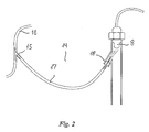
- a road surface detector means 8 mounted on a vehicle for contact-less detection of the surface properties of the road surface and providing an output accordingly is shown in Fig. 2.
- the detector means 8 comprises a radiation transmitter directed to the road surface and at least one receiver for receiving the radiation returned from the road surface and providing an output accordingly.
- the detector means 8 comprises washing means 14 for the transmitter and the at least one receiver for recurrently flushing thereof, comprising a Y-branch 15 in the tube 16 connecting the pump of the windshield washer system of the vehicle and the nozzles for distributing the cleaning liquid onto the windshield.
- a second tube 17 directs a part of this liquid to a nozzle 18 that flushes the detector means 8 every time the driver of the vehicle actuates the windshield washer system.
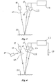
- Figs. 3-6 Various embodiments of sensor devices according to the present invention are shown in Figs. 3-6. They all comprises a light source 19 that emits light in the visible range towards a surface 20, in particularly the surface of a road, and two detectors 21, 22 for detecting the reflection of the emitted light from the surface 20 and providing an output accordingly to a control unit 23, a linear polarization filter 24 between the light source 19 and the surface 20, so that the light that meets the surface 20 is polarized, and a linear polarization filter 25 in front of one of the detectors 21, 22, so that the variation in the output from the two detectors 21, 22 will be representative for the variation in mirror reflected light and diffuse reflected light from the surface 20, as the mirror reflected light will preserve its original polarization whereas the diffuse reflected light substantially will become depolarized.
- a light source 19 that emits light in the visible range towards a surface 20, in particularly the surface of a road
- two detectors 21, 22 for detecting the reflection of the emitted light from the surface 20 and providing an
- the light source 19 and the detectors 21, 22 may be situated very closely together and the angle between the incoming and reflected light is normally within the range of 0° to 15°, and the angle between the incoming light and the surface normal will normally be within the range of 0° to 6°.
- the angles on the figures are exaggerated in order to illustrate the principles more clearly.
- the sensor is quite insensitive to the actual vertical distance between the sensor and the road surface 20 so that the same sensor may be installed in different types of vehicles and the quality of the output will not be deteriorated by the variations in the vertical distance during operation of the vehicle.
- the sensor device shown in Fig. 3 has a very simple configuration, in that the light source 19 and the two detectors 21, 22 are arranged side by side so that the light follows a separate path for each of the three. However, due to the small angles between the paths, the two detectors 21, 22 will be subjected to substantially the same intensity of mirror reflected light and diffuse reflected light.
- a linear polarization filter 25 is arranged in the path of the reflected light to one of the detectors 21 and the filter 25 has a direction of polarization perpendicular to the polarization direction of the filter 24 in front of the light source 19, so that the detector 21 will receive the diffuse reflected light and produce an output to the control means 23 accordingly, whereas the other detector 22 will receive the mirror reflected light as well as the diffuse reflected light and produce an output to the control means 23 accordingly.
- the difference between the two outputs will be a measure of the intensity of the mirror reflected light.
- the configuration may be improved with another linear polarization filter 26 arranged in front of the other detector 22 and with a polarization direction parallel to the one of the filter 24 in front of the light source 19 as shown in Fig. 4.
- the other detector 22 will receive the mirror reflected light plus only about half of the diffuse reflected light and produce an output to the control means 23 accordingly.
- the amplitude variation of the output from the other detector 22 due to the presence of mirror reflection will be enhanced which improves the signal-to-noise ratio of the device.
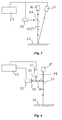
- the configuration has been improved with the presence of two extra features, an infrared light source 27 used as a reference light for verification of the function of the system, and a microphone 28 for receiving the noise form the vehicle travelling along a road and producing an output to the control means accordingly.
- Both features may be implemented either alone or in combination, into each of the shown embodiments of the invention as well as other embodiments thereof.
- the infrared reference light source 27 is arranged to emit light substantially in the direction and path of the first light source 19 by means of a beam splitter 29 arranged in that path.
- the polarization filters 24, 25, 26 have substantially no effect on the infrared light, so that the detection of the light from the reference light source by the first and second detector may be used for verification of the function of the system, correction for temporarily reduced transmittance of the light e.g. due to soiling of lenses or transparent covers, etc.
- the infrared reference light source 27 emits light within the wavelength range of 930 nm to 970 nm, which is one of the wavelength areas where water in particular absorbs radiation, and the light source 27 may be used for spectroscopic measurement of whether liquid water is present on the surface, which in combination with the measurements of diffuse and mirror reflected light may give a precise indication of the surface conditions of the road.
- the control means 23 may thereby distinguish between mirror reflection from water and from ice, which does not absorb infrared light to the same degree.
- the analysis of the noise collected by the microphone 28 is performed by the control means 23 and an example of how this analysis may be conducted is disclosed in US 5,852,243 by Chang et al . This analysis is likewise used as a supplement to the measurement of the diffuse and mirror reflected light to distinguish between the presence of ice or water on the road surface.
- FIG. 5 yet another configuration of the sensor device is shown, in which only one and the same linear polarization filter 24, 25 is used for the light emitted from the light source 19 towards the surface 20 and the light reflected from the surface towards one of the detectors 22.
- the light source 19 is directed perpendicularly towards the surface 20 and a beam splitter 29 is arranged in the path of the reflected light towards the detector 22, which in this configuration is identical to the path of the light from the light source 19 towards the surface 20.
- Fig. 5 yet another configuration of the sensor device is shown, in which only one and the same linear polarization filter 24, 25 is used for the light emitted from the light source 19 towards the surface 20 and the light reflected from the surface towards one of the detectors 22.
- the light source 19 is directed perpendicularly towards the surface 20 and a beam splitter 29 is arranged in the path of the reflected light towards the detector 22, which in this configuration is identical to the path of the light from the light source 19 towards the surface 20.
- another beam splitter 30 is added for dividing the light from the first beam splitter 29 for both detectors 21, 22 so that all light to and from the sensor device may be passed through a small opening or thin tube, which is easy to maintain clean, and the sensitivity to the distance between the sensor device and the surface 20 may be substantially completely eliminated.
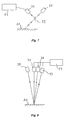
- FIGs. 7 and 8 Two other devices that may be used a supplement to the measurement of the diffuse and mirror reflected light to distinguish between the presence of ice or water on the road surface are shown in Figs. 7 and 8.
- a retro-reflection sensor is shown in Fig. 7, comprising a light source 31, which emits light at an angle of 45° towards the surface and a detector 32 arranged to receive the retro-reflected light by means of a beam splitter 33 and producing an output accordingly to the control means 23.
- the retro-reflection sensor is used for the detection of ice crystals on the surface, i.e. mainly the presence of snow or rime.
- a sensor device for colour separation of reflected polychromatic light comprising a source 34 of polychromatic visible light, such as white light, and three detectors 35, 36, 37 for detection of the amount of light within the red, green and blue range, respectively, of the reflected light and providing outputs to the control means 23.
- the results may be used to verify the measurements of the mirror and diffuse reflected light and may also be used to correct these measurements due to the features of the surface that are detected by the colour separation, e.g. whether the surface is made from concrete or asphalt, is painted etc.
Landscapes
- Physics & Mathematics (AREA)
- General Physics & Mathematics (AREA)
- Engineering & Computer Science (AREA)
- Life Sciences & Earth Sciences (AREA)
- Atmospheric Sciences (AREA)
- Biochemistry (AREA)
- Multimedia (AREA)
- Health & Medical Sciences (AREA)
- Chemical & Material Sciences (AREA)
- Analytical Chemistry (AREA)
- Transportation (AREA)
- General Health & Medical Sciences (AREA)
- Immunology (AREA)
- Pathology (AREA)
- Mechanical Engineering (AREA)
- Theoretical Computer Science (AREA)
- Investigating Or Analysing Materials By Optical Means (AREA)
- Vehicle Body Suspensions (AREA)
- Length Measuring Devices With Unspecified Measuring Means (AREA)
- Accessory Devices And Overall Control Thereof (AREA)
- Arrangements For Transmission Of Measured Signals (AREA)
- Traffic Control Systems (AREA)
Priority Applications (3)
| Application Number | Priority Date | Filing Date | Title |
|---|---|---|---|
| PL04720588T PL1606784T3 (pl) | 2003-03-14 | 2004-03-15 | Urządzenie do wykrywania stanu nawierzchni drogi |
| EP07019752A EP1890128B1 (en) | 2003-03-14 | 2004-03-15 | A device for detection of road surface condition |
| DK07019752.0T DK1890128T3 (da) | 2003-03-14 | 2004-03-15 | Anordning til detektering af vejoverfladetilstand |
Applications Claiming Priority (3)
| Application Number | Priority Date | Filing Date | Title |
|---|---|---|---|
| DKPA200300386 | 2003-03-14 | ||
| DK200300386 | 2003-03-14 | ||
| PCT/DK2004/000168 WO2004081897A2 (en) | 2003-03-14 | 2004-03-15 | A device for detection of road surface condition |
Related Child Applications (1)
| Application Number | Title | Priority Date | Filing Date |
|---|---|---|---|
| EP07019752A Division EP1890128B1 (en) | 2003-03-14 | 2004-03-15 | A device for detection of road surface condition |
Publications (2)
| Publication Number | Publication Date |
|---|---|
| EP1606784A2 EP1606784A2 (en) | 2005-12-21 |
| EP1606784B1 true EP1606784B1 (en) | 2007-10-10 |
Family
ID=32981681
Family Applications (2)
| Application Number | Title | Priority Date | Filing Date |
|---|---|---|---|
| EP04720588A Expired - Lifetime EP1606784B1 (en) | 2003-03-14 | 2004-03-15 | A device for detection of road surface condition |
| EP07019752A Expired - Lifetime EP1890128B1 (en) | 2003-03-14 | 2004-03-15 | A device for detection of road surface condition |
Family Applications After (1)
| Application Number | Title | Priority Date | Filing Date |
|---|---|---|---|
| EP07019752A Expired - Lifetime EP1890128B1 (en) | 2003-03-14 | 2004-03-15 | A device for detection of road surface condition |
Country Status (17)
| Country | Link |
|---|---|
| US (2) | US7652584B2 (zh) |
| EP (2) | EP1606784B1 (zh) |
| JP (1) | JP4492883B2 (zh) |
| KR (1) | KR20050109565A (zh) |
| CN (1) | CN1809853B (zh) |
| AT (2) | ATE534896T1 (zh) |
| AU (2) | AU2004219513B2 (zh) |
| CA (1) | CA2518386A1 (zh) |
| DE (1) | DE602004009422T2 (zh) |
| DK (2) | DK1606784T3 (zh) |
| EA (1) | EA008399B1 (zh) |
| ES (1) | ES2295838T3 (zh) |
| HK (1) | HK1117903A1 (zh) |
| NO (1) | NO20054213D0 (zh) |
| NZ (2) | NZ542080A (zh) |
| PL (1) | PL1606784T3 (zh) |
| WO (1) | WO2004081897A2 (zh) |
Cited By (3)
| Publication number | Priority date | Publication date | Assignee | Title |
|---|---|---|---|---|
| DE102008038037A1 (de) | 2008-08-16 | 2010-02-18 | Wabco Gmbh | Verfahren und Vorrichtung zur fahrdynamischen Regelung eines Fahrzeugs |
| DE102011015457A1 (de) | 2010-06-30 | 2012-01-05 | Wabco Gmbh | Verfahren und Vorrichtung zur Erkennung einer Fahrzeugbewegung |
| DE102013021797A1 (de) | 2013-12-23 | 2015-06-25 | Hella Kgaa Hueck & Co. | Verfahren zur Abgabe eines Warnhinweises auf einen gefährlichen Fahrbahnzustand und Vorrichtung |
Families Citing this family (87)
| Publication number | Priority date | Publication date | Assignee | Title |
|---|---|---|---|---|
| US8983771B2 (en) | 1997-10-22 | 2015-03-17 | Intelligent Technologies International, Inc. | Inter-vehicle information conveyance system and method |
| JP4492883B2 (ja) * | 2003-03-14 | 2010-06-30 | エルイダヴルトヴェエエーエス エーペーエス | 表面状態データの検出用デバイス |
| DE10353001A1 (de) * | 2003-11-13 | 2005-06-16 | Conti Temic Microelectronic Gmbh | Vorrichtung und Verfahren zur Objekterkennung für eine Kraftfahrzeug-Sicherheitseinrichtung |
| EP1770669B1 (en) * | 2004-07-16 | 2009-12-30 | Fourie | Road condition informing apparatus, system and method |
| US20070040683A1 (en) * | 2005-08-22 | 2007-02-22 | Neal Oliver | Light-activated RFID tag |
| US20070131851A1 (en) * | 2005-12-14 | 2007-06-14 | Nevine Holtz | Polarimetric detection of road signs |
| FR2897950B1 (fr) * | 2006-02-24 | 2008-05-30 | Peugeot Citroen Automobiles Sa | Procede de caracterisation d'une surface routiere |
| FR2897949B1 (fr) * | 2006-02-24 | 2008-05-30 | Peugeot Citroen Automobiles Sa | Systeme de caracterisation d'une surface routiere |
| FR2897938B1 (fr) * | 2006-02-24 | 2008-04-18 | Peugeot Citroen Automobiles Sa | Procede d'estimation de l'adherence d'une surface |
| DE102006046109A1 (de) * | 2006-09-28 | 2008-04-03 | Carl Zeiss Microimaging Gmbh | Laser-Scanning-Mikroskop und Laser-Scanning-Mikroskopierverfahren zur Messung von diffus reflektierter Beleuchtungsstrahlung |
| US8180518B2 (en) * | 2008-04-15 | 2012-05-15 | Robert Bosch Gmbh | System and method for determining microenvironment conditions external to a vehicle |
| EP2138352B1 (de) * | 2008-06-24 | 2010-04-07 | SMR PATENTS S.à.r.l. | Optisches System und Verfahren zur Erkennung von optischer Verschleierung in einem Fahrzeug |
| US7986408B2 (en) * | 2008-11-05 | 2011-07-26 | Rosemount Aerospace Inc. | Apparatus and method for in-flight detection of airborne water droplets and ice crystals |
| DE102009032314A1 (de) | 2009-07-09 | 2011-01-13 | Wabco Gmbh | Verfahren zur korrekten Durchführung von autonomen Notbremsungen bei einem Straßenfahrzeug |
| CN102753818A (zh) * | 2009-07-23 | 2012-10-24 | 利瓦斯有限责任公司 | 翼形件上的冰的检测 |
| US8144325B2 (en) | 2009-07-23 | 2012-03-27 | Rosemount Aerospace, Inc. | In-flight multiple field of view detector for supercooled airborne water droplets |
| FI122084B (fi) | 2009-12-03 | 2011-08-15 | Teconer Oy | Päätelaiteperusteinen tieolosuhteiden kartoitusmenetelmä ja -järjestelmä |
| DE102010020537A1 (de) * | 2010-05-14 | 2011-11-17 | H&S Robotic Solutions GbR (vertretungsberechtigter Gesellschafter: Bernd-Helge Schäfer, 67661 Kaiserslautern) | Wasserdetektor |
| GB2480716A (en) * | 2010-05-18 | 2011-11-30 | Per Magnussen | Road surface and tyre condition monitoring apparatus |
| DE102010023856A1 (de) * | 2010-06-15 | 2011-12-22 | Wabco Gmbh | Sensor zur berührungslosen Bestimmung der Fahrbahnbeschaffenheit und dessen Verwendung |
| DE102011015527A1 (de) * | 2010-06-15 | 2011-12-15 | Wabco Gmbh | Sensor zur berührungslosen Bestimmung der Fahrbahnbeschaffenheit und dessen Verwendung |
| DE102010025703A1 (de) * | 2010-06-30 | 2012-01-05 | Wabco Gmbh | Verfahren und Vorrichtung zur Ausbringung von Streugut auf eine Fahrbahn und mit einer solchen Vorrichtung ausgerüstetes Fahrzeug |
| DE102011015510A1 (de) * | 2010-06-30 | 2012-01-05 | Wabco Gmbh | Verfahren und Vorrichtung zur Steuerung einer Traktionshilfe eines Fahrzeuges |
| DE102011015509A1 (de) | 2010-06-30 | 2012-01-05 | Wabco Gmbh | Verfahren und Vorrichtung zur Steuerung zumindest eines Fahrerassistenzsystems eines Fahrzeuges und damit ausgestattetes Fahrzeug |
| DE102010025719A1 (de) | 2010-06-30 | 2012-05-16 | Wabco Gmbh | Vorrichtung und Verfahren zur Ausgabe eines Signals bei gefährlichem Untergrund unter einem Fahrzeug |
| DE102010050634A1 (de) * | 2010-11-05 | 2012-05-10 | Wabco Gmbh | Steuereinrichtung für ein Fahrzeug-Regelsystem und Verfahren zur Ermittlung von Reifenzuständen von Fahrzeugreifen |
| JP5272042B2 (ja) * | 2011-05-12 | 2013-08-28 | 富士重工業株式会社 | 環境認識装置および環境認識方法 |
| JP5892876B2 (ja) * | 2011-07-28 | 2016-03-23 | クラリオン株式会社 | 車載用環境認識装置 |
| DE102011082123A1 (de) * | 2011-09-05 | 2013-03-07 | Robert Bosch Gmbh | Verfahren zum Betreiben eines Fahrzeuges |
| CN102982304B (zh) | 2011-09-07 | 2016-05-25 | 株式会社理光 | 利用偏光图像检测车辆位置的方法和系统 |
| KR101326991B1 (ko) * | 2011-12-01 | 2013-11-13 | 현대자동차주식회사 | 노면의 성질 감지 장치 및 그 방법 |
| WO2013110072A1 (en) * | 2012-01-20 | 2013-07-25 | University Of Alaska | Surface feature detection by radiation analysis |
| JP5907271B2 (ja) * | 2012-08-08 | 2016-04-26 | 日産自動車株式会社 | 路面状態検出装置及び路面状態検出方法 |
| WO2014031870A2 (en) | 2012-08-22 | 2014-02-27 | University Of Alaska | Management of tax information based on topographical information |
| CN102890881B (zh) * | 2012-10-17 | 2015-04-08 | 湖州金博电子技术有限公司 | 一种拖拉机田间作业考试系统 |
| DE102012219721A1 (de) * | 2012-10-29 | 2014-04-30 | Robert Bosch Gmbh | Fahrassistenzverfahren und Fahrassistenzsystem zur Erhöhung des Fahrkomforts |
| CN102967561B (zh) * | 2012-12-11 | 2015-07-15 | 河南中原光电测控技术有限公司 | 一种后向多波长红外光谱非接触式路面状况检测方法 |
| US9082201B2 (en) | 2013-01-04 | 2015-07-14 | International Business Machines Corporation | Surface contamination determination system |
| DE102013201741A1 (de) * | 2013-02-04 | 2014-08-21 | Robert Bosch Gmbh | System zur Erfassung einer Fahrbahnbeschaffenheit |
| CN103197355A (zh) * | 2013-04-01 | 2013-07-10 | 苏州盖娅智能科技有限公司 | 一种积雪探测器 |
| JP6105371B2 (ja) * | 2013-04-25 | 2017-03-29 | 株式会社荏原製作所 | 研磨方法および研磨装置 |
| CN109114489A (zh) * | 2013-05-07 | 2019-01-01 | 飞利浦灯具控股公司 | 具有传感器的用于道路照明的照明器 |
| CN103366580B (zh) * | 2013-06-28 | 2015-08-12 | 苏州奥特福环境科技有限公司 | 非接触式路况检测系统 |
| CN103389075B (zh) * | 2013-07-22 | 2015-07-22 | 北京理工大学 | 基于可见光偏振成像的实时非接触水面波纹测量方法 |
| DE102013220250A1 (de) * | 2013-10-08 | 2014-09-11 | Schaeffler Technologies Gmbh & Co. Kg | Vorrichtung für ein Fahrzeug zum Erkennen der Beschaffenheit einer Oberfläche und Verfahren zum Erkennen der Beschaffenheit einer Oberfläche beim Betrieb eines Fahrzeugs |
| WO2015060910A1 (en) * | 2013-10-24 | 2015-04-30 | The Regents Of The University Of Michigan | Ice and water detection system |
| BR112016009205B1 (pt) * | 2013-10-24 | 2021-03-30 | The Regents Of The University Of Michigan | Sistema de detecção de gelo e água super-resfriada |
| WO2015070873A1 (en) | 2013-11-13 | 2015-05-21 | Drugster Aps | Detection of substances in liquids, in particular psychoactive substances |
| DE102014106939A1 (de) * | 2014-05-16 | 2015-11-19 | Huf Hülsbeck & Fürst Gmbh & Co. Kg | Elektronische Baugruppe zum Beleuchten eines einen Detektionsbereich eines Sensors markierenden Zielbereiches |
| DE102014107358A1 (de) * | 2014-05-26 | 2015-11-26 | Dr. Ing. H.C. F. Porsche Aktiengesellschaft | Vorrichtung und Verfahren zum Erfassen von Nässe auf einer Fahrbahn |
| US9090264B1 (en) * | 2014-06-12 | 2015-07-28 | GM Global Technology Operations LLC | Vision-based wet road surface detection |
| US20160052644A1 (en) * | 2014-08-20 | 2016-02-25 | Elwha Llc | Unmanned aerial vehicle having an onboard cleaning device |
| US9993852B2 (en) | 2014-08-20 | 2018-06-12 | Elwha Llc | Surface cleaning unmanned aerial vehicle |
| CN104477122A (zh) * | 2014-11-19 | 2015-04-01 | 柳州航盛科技有限公司 | 车辆行车安全系统 |
| CN104537209B (zh) * | 2014-12-09 | 2017-04-05 | 上海交通大学 | 基于隐马尔科夫模型的车辆行驶道路类型的判断方法 |
| US9453941B2 (en) * | 2014-12-22 | 2016-09-27 | GM Global Technology Operations LLC | Road surface reflectivity detection by lidar sensor |
| DE102015208429A1 (de) | 2015-05-06 | 2016-11-10 | Continental Teves Ag & Co. Ohg | Verfahren und Vorrichtung zur Erkennung und Bewertung von Fahrbahnreflexionen |
| DE102015214834A1 (de) * | 2015-08-04 | 2017-02-09 | Robert Bosch Gmbh | Konzept zum Lokalisieren eines sich innerhalb eines Parkplatzes befindenden gegenständlichen Körpers |
| US10336465B2 (en) | 2016-01-08 | 2019-07-02 | The Regents Of The University Of Michigan | Ice crystals and volcanic ash detection system |
| US10360459B2 (en) * | 2016-04-06 | 2019-07-23 | Panasonic Intellectual Property Management Co., Ltd. | Detection device, detection method, and non-transitory computer-readable recording medium storing detection program |
| JP6776614B2 (ja) * | 2016-05-18 | 2020-10-28 | 株式会社リコー | 路面状態判別システムおよび移動体 |
| DE102016210379A1 (de) * | 2016-06-13 | 2017-12-14 | Robert Bosch Gmbh | Sensorvorrichtung für ein Fahrzeug |
| US11137519B2 (en) * | 2016-07-21 | 2021-10-05 | Rosemount Aerospace Inc. | Multi-fiber optical sensor for icing |
| US9802545B1 (en) * | 2017-01-18 | 2017-10-31 | Ford Global Technologies, Llc | Motor vehicle ice sensor assembly and method of operation |
| WO2018140822A1 (en) * | 2017-01-26 | 2018-08-02 | Tallyho! Inc. | System for object detection |
| JP6837690B2 (ja) * | 2017-01-27 | 2021-03-03 | マサチューセッツ インスティテュート オブ テクノロジー | 表面貫通レーダーを用いた乗物位置特定方法およびシステム |
| CN107103775B (zh) * | 2017-05-18 | 2020-01-14 | 西安理工大学 | 一种基于群智计算的道路质量检测方法 |
| CN109094566A (zh) * | 2017-06-21 | 2018-12-28 | 奥迪股份公司 | 车辆驾驶辅助系统和方法 |
| RU2671385C1 (ru) * | 2017-08-28 | 2018-10-30 | АКЦИОНЕРНОЕ ОБЩЕСТВО "Моринформсистема-Агат-КИП" (АО "Моринсис-Агат-КИП") | Устройство для оценки состояния дорожного покрытия |
| JP6664360B2 (ja) * | 2017-09-08 | 2020-03-13 | 本田技研工業株式会社 | 判定装置および車両 |
| DE102017122979A1 (de) * | 2017-10-04 | 2019-04-04 | HELLA GmbH & Co. KGaA | Verfahren zur Erfassung von Feuchtigkeit auf einer Fahrbahn |
| EP3701417A1 (en) * | 2017-10-27 | 2020-09-02 | 3M Innovative Properties Company | Optical sensor systems |
| DE102017219610A1 (de) * | 2017-11-06 | 2019-05-09 | Robert Bosch Gmbh | Verfahren zur Bestimmung eines Typus eines Hydrometeors |
| US10435020B2 (en) | 2017-12-01 | 2019-10-08 | Robert Bosch Gmbh | Lane keeping support on roads covered by snow |
| EP3536574A1 (en) * | 2018-03-06 | 2019-09-11 | Pablo Alvarez Troncoso | Vehicle control system |
| DE102018203807A1 (de) * | 2018-03-13 | 2019-09-19 | Continental Teves Ag & Co. Ohg | Verfahren und Vorrichtung zur Erkennung und Bewertung von Fahrbahnzuständen und witterungsbedingten Umwelteinflüssen |
| US10621865B2 (en) | 2018-03-29 | 2020-04-14 | The Regents Of The University Of Michigan | Road condition monitoring system |
| CN109752774A (zh) * | 2018-06-05 | 2019-05-14 | 启迪云控(北京)科技有限公司 | 基于车辆行为数据的气象预测方法、系统 |
| JP2020030175A (ja) * | 2018-08-24 | 2020-02-27 | 株式会社システック | 水と氷を分別した降水量測定装置 |
| JP6731020B2 (ja) * | 2018-09-03 | 2020-07-29 | 株式会社Subaru | 車外環境認識装置および車外環境認識方法 |
| US10508952B1 (en) | 2018-10-31 | 2019-12-17 | The Regents Of The University Of Michigan | Optimum spectral bands for active vision systems |
| DE102019208881A1 (de) * | 2019-06-19 | 2020-12-24 | Robert Bosch Gmbh | Vorrichtung und Verfahren zur Ermittlung eines Oberflächenzustands einer von einem Fahrzeug befahrenen oder zu befahrenden Fahrbahn |
| CN110396903A (zh) * | 2019-08-05 | 2019-11-01 | 廊坊市交通公路工程有限公司 | 粉质土路基压实度检测方法 |
| US11035982B1 (en) * | 2019-12-06 | 2021-06-15 | CEM Products, LLC | Snow sensors and assemblies for use with same |
| US11885661B2 (en) | 2020-02-17 | 2024-01-30 | Wiliot, LTD. | Detecting material type using low-energy sensing |
| CN113362518B (zh) * | 2020-03-06 | 2022-04-26 | 杭州海康威视数字技术股份有限公司 | 道闸状态控制方法、装置及电子设备 |
| US20220282436A1 (en) * | 2021-03-04 | 2022-09-08 | Nec Corporation Of America | Infrared retroreflective spheres for enhanced road marks |
Family Cites Families (43)
| Publication number | Priority date | Publication date | Assignee | Title |
|---|---|---|---|---|
| US3836846A (en) * | 1971-09-09 | 1974-09-17 | Monsanto Co | Ice detection apparatus employing microwave reflectance |
| DE2712199C2 (de) | 1977-03-19 | 1979-05-03 | Peter Dipl.-Ing. Dr.-Ing. 8000 Muenchen Decker | Vorrichtung zum Warnen vor Straßenglätte |
| US4274091A (en) * | 1978-03-09 | 1981-06-16 | Decker Peter W | Road surface ice detector and method for vehicles |
| DE3023444C2 (de) | 1979-06-29 | 1985-07-11 | Omron Tateisi Electronics Co., Kyoto | Einrichtung zur Ermittlung des witterungsbedingten Straßenzustandes |
| JPS6015015B2 (ja) * | 1979-06-29 | 1985-04-17 | 株式会社 レオ技研 | 路面水分検知装置 |
| DE3205129C2 (de) | 1982-02-12 | 1984-10-04 | Happel GmbH & Co, 4690 Herne | Vorrichtung zum Erkennen von Eis- und/oder Reifbildung |
| US4844584A (en) * | 1986-06-26 | 1989-07-04 | Fuji Photo Film Co., Ltd. | Semiconductor laser beam splitting device |
| US4786815A (en) * | 1987-02-12 | 1988-11-22 | K. J. Law Engineers, Inc. | Non-contact sensor with particular utility for measurement of road profile |
| US4884584A (en) * | 1987-08-14 | 1989-12-05 | National Coupling Company, Inc. | Internally preloaded metal-to-metal seal hydraulic connector |
| JPH0820238B2 (ja) | 1989-09-26 | 1996-03-04 | 日産自動車株式会社 | 路面状態検出装置 |
| DE4008280A1 (de) * | 1990-03-15 | 1991-09-19 | Tzn Forschung & Entwicklung | Verfahren zur ermittlung des fahrbahnoberflaechenzustandes |
| FR2665959B1 (fr) * | 1990-08-16 | 1994-01-14 | Oreal | Appareil destine a permettre d'evaluer la brillance d'une surface, en particulier de la peau. |
| US5428544A (en) * | 1990-11-05 | 1995-06-27 | Norm Pacific Automation Corporation | Traffic information inter-vehicle transference and navigation system |
| DE4205629A1 (de) | 1992-02-25 | 1993-08-26 | Tzn Forschung & Entwicklung | Verfahren zur beruehrungslosen messung des tausalzgehaltes und vorrichtung zur durchfuehrung des verfahrens |
| US5541413A (en) * | 1992-04-24 | 1996-07-30 | Thiokol Corporation | Acousto-optic tunable filter-based surface scanning system and process |
| US5243185A (en) * | 1992-07-31 | 1993-09-07 | Loral Aerospace Corp. | Apparatus and method for ice detection |
| US5589822A (en) * | 1992-10-20 | 1996-12-31 | Robotic Vision Systems, Inc. | System for detecting ice or snow on surface which specularly reflects light |
| US5475370A (en) * | 1992-10-20 | 1995-12-12 | Robotic Vision Systems, Inc. | System for detecting ice or snow on surface which specularly reflects light |
| DE4300896C1 (de) * | 1993-01-15 | 1994-04-21 | Holger Dipl Ing Oldenettel | Verfahren und Vorrichtung zur Ermittlung des Fahrbahnoberflächenzustandes |
| JPH06307838A (ja) | 1993-04-28 | 1994-11-04 | Isuzu Motors Ltd | 路面状態検知装置 |
| US5652655A (en) * | 1993-06-29 | 1997-07-29 | Omron Corporation | Road surface discriminator and apparatus applying same |
| JP3358099B2 (ja) * | 1994-03-25 | 2002-12-16 | オムロン株式会社 | 光学式センサ装置 |
| CA2156892A1 (en) * | 1994-08-25 | 1996-02-26 | Andrew S. Inenaga | Method and apparatus for precipitation detection and differentiation |
| EP0720137B1 (en) * | 1994-12-28 | 2007-02-21 | Omron Corporation | Traffic information system |
| DE19506550A1 (de) * | 1995-02-24 | 1996-08-29 | Inst Chemo Biosensorik | Verfahren zur verzugsfreien Feststellung von und zur Warnung vor durch Glättebildung bedingte Gefahren und Vorrichtung zur Durchführung des Verfahrens |
| US5650610A (en) * | 1995-03-15 | 1997-07-22 | National Research Council Of Canada | Apparatus and method for remote detection of ice or other birefringent material on a surface |
| JPH08263784A (ja) * | 1995-03-23 | 1996-10-11 | Honda Motor Co Ltd | 道路状況認識装置 |
| US6370475B1 (en) * | 1997-10-22 | 2002-04-09 | Intelligent Technologies International Inc. | Accident avoidance system |
| US6720920B2 (en) * | 1997-10-22 | 2004-04-13 | Intelligent Technologies International Inc. | Method and arrangement for communicating between vehicles |
| US6535141B1 (en) * | 1996-06-07 | 2003-03-18 | John A. Doherty | Vehicle mounted travel surface and weather condition monitoring system |
| US5652522A (en) * | 1995-09-21 | 1997-07-29 | Hughes Electronics | Dielectric-loaded surface-condition sensor and method |
| US5710554A (en) * | 1996-02-01 | 1998-01-20 | Pettler; Peter R. | Pavement ice detector |
| DE19643454C2 (de) * | 1996-10-10 | 2003-08-21 | Mannesmann Ag | Verfahren und Vorrichtung zur Übermittlung von Daten zur Verkehrslagebeurteilung |
| US5852243A (en) * | 1997-07-21 | 1998-12-22 | J-Squared, Llc | Method and apparatus for detecting a road pavement surface condition |
| US7271737B1 (en) * | 1998-01-27 | 2007-09-18 | Hoffberg Steven M | Mobile communication device |
| GB9802473D0 (en) * | 1998-02-06 | 1998-04-01 | British Gas Plc | Method and apparatus to detect the presence of water on a surface |
| US6166645A (en) * | 1999-01-13 | 2000-12-26 | Blaney; Kevin | Road surface friction detector and method for vehicles |
| US6173231B1 (en) * | 2000-01-31 | 2001-01-09 | Navigation Technologies Corp. | Method and system for collecting data concerning thermal properties of roads for a geographic database and use thereof in a vehicle safety system |
| CN1264824A (zh) * | 2000-03-20 | 2000-08-30 | 华中理工大学 | 用于表面形貌测量的位移传感器 |
| JP3811366B2 (ja) | 2000-04-21 | 2006-08-16 | 住友ゴム工業株式会社 | 路面情報配信システム、車両の情報集約配信システムおよび車両の情報発信装置、ならびに車両制御プログラム |
| EP1213569B1 (de) * | 2000-12-08 | 2006-05-17 | Gretag-Macbeth AG | Vorrichtung zur bildelementweisen Ausmessung eines flächigen Messobjekts |
| JP4492883B2 (ja) * | 2003-03-14 | 2010-06-30 | エルイダヴルトヴェエエーエス エーペーエス | 表面状態データの検出用デバイス |
| US7119336B2 (en) * | 2003-06-20 | 2006-10-10 | The Boeing Company | Method of measuring coating using two-wavelength infrared reflectance |
-
2004
- 2004-03-15 JP JP2006504327A patent/JP4492883B2/ja not_active Expired - Fee Related
- 2004-03-15 AT AT07019752T patent/ATE534896T1/de active
- 2004-03-15 EP EP04720588A patent/EP1606784B1/en not_active Expired - Lifetime
- 2004-03-15 DK DK04720588T patent/DK1606784T3/da active
- 2004-03-15 NZ NZ542080A patent/NZ542080A/en unknown
- 2004-03-15 EP EP07019752A patent/EP1890128B1/en not_active Expired - Lifetime
- 2004-03-15 US US10/549,354 patent/US7652584B2/en not_active Expired - Fee Related
- 2004-03-15 NZ NZ568833A patent/NZ568833A/en unknown
- 2004-03-15 AT AT04720588T patent/ATE375585T1/de active
- 2004-03-15 DE DE602004009422T patent/DE602004009422T2/de not_active Expired - Lifetime
- 2004-03-15 CN CN2004800069887A patent/CN1809853B/zh not_active Expired - Fee Related
- 2004-03-15 PL PL04720588T patent/PL1606784T3/pl unknown
- 2004-03-15 ES ES04720588T patent/ES2295838T3/es not_active Expired - Lifetime
- 2004-03-15 DK DK07019752.0T patent/DK1890128T3/da active
- 2004-03-15 CA CA002518386A patent/CA2518386A1/en not_active Abandoned
- 2004-03-15 EA EA200501458A patent/EA008399B1/ru not_active IP Right Cessation
- 2004-03-15 AU AU2004219513A patent/AU2004219513B2/en not_active Ceased
- 2004-03-15 WO PCT/DK2004/000168 patent/WO2004081897A2/en active IP Right Grant
- 2004-03-15 KR KR1020057017102A patent/KR20050109565A/ko active IP Right Grant
-
2005
- 2005-09-12 NO NO20054213A patent/NO20054213D0/no not_active Application Discontinuation
-
2008
- 2008-07-25 HK HK08108271.5A patent/HK1117903A1/xx not_active IP Right Cessation
-
2009
- 2009-11-27 AU AU2009240864A patent/AU2009240864A1/en not_active Abandoned
- 2009-12-09 US US12/634,386 patent/US8040248B2/en not_active Expired - Fee Related
Cited By (4)
| Publication number | Priority date | Publication date | Assignee | Title |
|---|---|---|---|---|
| DE102008038037A1 (de) | 2008-08-16 | 2010-02-18 | Wabco Gmbh | Verfahren und Vorrichtung zur fahrdynamischen Regelung eines Fahrzeugs |
| DE102011015457A1 (de) | 2010-06-30 | 2012-01-05 | Wabco Gmbh | Verfahren und Vorrichtung zur Erkennung einer Fahrzeugbewegung |
| WO2012000603A1 (de) | 2010-06-30 | 2012-01-05 | Wabco Gmbh | Verfahren und vorrichtung zur erkennung einer fahrzeugbewegung |
| DE102013021797A1 (de) | 2013-12-23 | 2015-06-25 | Hella Kgaa Hueck & Co. | Verfahren zur Abgabe eines Warnhinweises auf einen gefährlichen Fahrbahnzustand und Vorrichtung |
Also Published As
Similar Documents
| Publication | Publication Date | Title |
|---|---|---|
| EP1606784B1 (en) | A device for detection of road surface condition | |
| US8384555B2 (en) | Method and system for automated detection of mobile phone usage | |
| US7615750B2 (en) | Device for determining the surface condition of a roadway | |
| US5249027A (en) | Inter-vehicle distance measuring system | |
| JP3613275B2 (ja) | 交通情報システム | |
| CA2881241A1 (en) | Device and method for detecting an axle of a vehicle | |
| US20210110712A1 (en) | Device for detecting road surface water | |
| KR101760819B1 (ko) | 도로의 낙하물 신고 관리 시스템 및 낙하물 신고 방법 | |
| KR20140120284A (ko) | 도로의 낙하물 신고 관리 시스템 및 낙하물 신고 방법 | |
| KR100355160B1 (ko) | 무선 통신을 이용한 과속차량 탐지장치 | |
| KR102483121B1 (ko) | 스마트 도로조명시스템 | |
| KR102479392B1 (ko) | 차량용 블랙아이스 감지시스템 | |
| KR20010027668A (ko) | 광섬유 센서를 통한 차량감지및 교통정보 수집원리 | |
| KR20110008698A (ko) | 자동차 속도 감지 시스템 | |
| Duckworth et al. | Comparative study of nonintrusive traffic monitoring sensors | |
| FR2871915A1 (fr) | Procede actif de signalisation, a plusieurs centaines de metres de distance, de detresse et de danger. il est destine aux vehicules et aux usagers de la route | |
| JPH11144188A (ja) | 車載ビーコン受信機 |
Legal Events
| Date | Code | Title | Description |
|---|---|---|---|
| PUAI | Public reference made under article 153(3) epc to a published international application that has entered the european phase |
Free format text: ORIGINAL CODE: 0009012 |
|
| 17P | Request for examination filed |
Effective date: 20050830 |
|
| AK | Designated contracting states |
Kind code of ref document: A2 Designated state(s): AT BE BG CH CY CZ DE DK EE ES FI FR GB GR HU IE IT LI LU MC NL PL PT RO SE SI SK TR |
|
| AX | Request for extension of the european patent |
Extension state: AL LT LV MK |
|
| DAX | Request for extension of the european patent (deleted) | ||
| 17Q | First examination report despatched |
Effective date: 20051205 |
|
| GRAP | Despatch of communication of intention to grant a patent |
Free format text: ORIGINAL CODE: EPIDOSNIGR1 |
|
| RIN1 | Information on inventor provided before grant (corrected) |
Inventor name: FRIDTHJOF, JACK |
|
| GRAS | Grant fee paid |
Free format text: ORIGINAL CODE: EPIDOSNIGR3 |
|
| GRAA | (expected) grant |
Free format text: ORIGINAL CODE: 0009210 |
|
| AK | Designated contracting states |
Kind code of ref document: B1 Designated state(s): AT BE BG CH CY CZ DE DK EE ES FI FR GB GR HU IE IT LI LU MC NL PL PT RO SE SI SK TR |
|
| REG | Reference to a national code |
Ref country code: GB Ref legal event code: FG4D |
|
| REG | Reference to a national code |
Ref country code: CH Ref legal event code: EP |
|
| REG | Reference to a national code |
Ref country code: IE Ref legal event code: FG4D |
|
| REF | Corresponds to: |
Ref document number: 602004009422 Country of ref document: DE Date of ref document: 20071122 Kind code of ref document: P |
|
| REG | Reference to a national code |
Ref country code: SE Ref legal event code: TRGR |
|
| REG | Reference to a national code |
Ref country code: CH Ref legal event code: NV Representative=s name: TROESCH SCHEIDEGGER WERNER AG |
|
| REG | Reference to a national code |
Ref country code: DK Ref legal event code: T3 |
|
| REG | Reference to a national code |
Ref country code: PL Ref legal event code: T3 |
|
| REG | Reference to a national code |
Ref country code: ES Ref legal event code: FG2A Ref document number: 2295838 Country of ref document: ES Kind code of ref document: T3 |
|
| PG25 | Lapsed in a contracting state [announced via postgrant information from national office to epo] |
Ref country code: PT Free format text: LAPSE BECAUSE OF FAILURE TO SUBMIT A TRANSLATION OF THE DESCRIPTION OR TO PAY THE FEE WITHIN THE PRESCRIBED TIME-LIMIT Effective date: 20080310 Ref country code: BG Free format text: LAPSE BECAUSE OF FAILURE TO SUBMIT A TRANSLATION OF THE DESCRIPTION OR TO PAY THE FEE WITHIN THE PRESCRIBED TIME-LIMIT Effective date: 20080110 |
|
| ET | Fr: translation filed | ||
| PG25 | Lapsed in a contracting state [announced via postgrant information from national office to epo] |
Ref country code: CZ Free format text: LAPSE BECAUSE OF FAILURE TO SUBMIT A TRANSLATION OF THE DESCRIPTION OR TO PAY THE FEE WITHIN THE PRESCRIBED TIME-LIMIT Effective date: 20071010 |
|
| PLBE | No opposition filed within time limit |
Free format text: ORIGINAL CODE: 0009261 |
|
| STAA | Information on the status of an ep patent application or granted ep patent |
Free format text: STATUS: NO OPPOSITION FILED WITHIN TIME LIMIT |
|
| PG25 | Lapsed in a contracting state [announced via postgrant information from national office to epo] |
Ref country code: SK Free format text: LAPSE BECAUSE OF FAILURE TO SUBMIT A TRANSLATION OF THE DESCRIPTION OR TO PAY THE FEE WITHIN THE PRESCRIBED TIME-LIMIT Effective date: 20071010 Ref country code: RO Free format text: LAPSE BECAUSE OF FAILURE TO SUBMIT A TRANSLATION OF THE DESCRIPTION OR TO PAY THE FEE WITHIN THE PRESCRIBED TIME-LIMIT Effective date: 20071010 |
|
| 26N | No opposition filed |
Effective date: 20080711 |
|
| PG25 | Lapsed in a contracting state [announced via postgrant information from national office to epo] |
Ref country code: MC Free format text: LAPSE BECAUSE OF NON-PAYMENT OF DUE FEES Effective date: 20080331 |
|
| PG25 | Lapsed in a contracting state [announced via postgrant information from national office to epo] |
Ref country code: GR Free format text: LAPSE BECAUSE OF FAILURE TO SUBMIT A TRANSLATION OF THE DESCRIPTION OR TO PAY THE FEE WITHIN THE PRESCRIBED TIME-LIMIT Effective date: 20080111 Ref country code: EE Free format text: LAPSE BECAUSE OF FAILURE TO SUBMIT A TRANSLATION OF THE DESCRIPTION OR TO PAY THE FEE WITHIN THE PRESCRIBED TIME-LIMIT Effective date: 20071010 |
|
| PG25 | Lapsed in a contracting state [announced via postgrant information from national office to epo] |
Ref country code: FI Free format text: LAPSE BECAUSE OF FAILURE TO SUBMIT A TRANSLATION OF THE DESCRIPTION OR TO PAY THE FEE WITHIN THE PRESCRIBED TIME-LIMIT Effective date: 20071010 |
|
| PG25 | Lapsed in a contracting state [announced via postgrant information from national office to epo] |
Ref country code: SI Free format text: LAPSE BECAUSE OF FAILURE TO SUBMIT A TRANSLATION OF THE DESCRIPTION OR TO PAY THE FEE WITHIN THE PRESCRIBED TIME-LIMIT Effective date: 20071010 |
|
| PG25 | Lapsed in a contracting state [announced via postgrant information from national office to epo] |
Ref country code: CY Free format text: LAPSE BECAUSE OF FAILURE TO SUBMIT A TRANSLATION OF THE DESCRIPTION OR TO PAY THE FEE WITHIN THE PRESCRIBED TIME-LIMIT Effective date: 20071010 |
|
| PGFP | Annual fee paid to national office [announced via postgrant information from national office to epo] |
Ref country code: IE Payment date: 20100308 Year of fee payment: 7 |
|
| PGFP | Annual fee paid to national office [announced via postgrant information from national office to epo] |
Ref country code: PL Payment date: 20100310 Year of fee payment: 7 |
|
| PG25 | Lapsed in a contracting state [announced via postgrant information from national office to epo] |
Ref country code: LU Free format text: LAPSE BECAUSE OF NON-PAYMENT OF DUE FEES Effective date: 20080315 Ref country code: HU Free format text: LAPSE BECAUSE OF FAILURE TO SUBMIT A TRANSLATION OF THE DESCRIPTION OR TO PAY THE FEE WITHIN THE PRESCRIBED TIME-LIMIT Effective date: 20080411 |
|
| PGFP | Annual fee paid to national office [announced via postgrant information from national office to epo] |
Ref country code: DK Payment date: 20110324 Year of fee payment: 8 |
|
| PGFP | Annual fee paid to national office [announced via postgrant information from national office to epo] |
Ref country code: SE Payment date: 20110328 Year of fee payment: 8 Ref country code: AT Payment date: 20110328 Year of fee payment: 8 |
|
| PGFP | Annual fee paid to national office [announced via postgrant information from national office to epo] |
Ref country code: ES Payment date: 20110328 Year of fee payment: 8 Ref country code: CH Payment date: 20110427 Year of fee payment: 8 |
|
| PGFP | Annual fee paid to national office [announced via postgrant information from national office to epo] |
Ref country code: BE Payment date: 20110414 Year of fee payment: 8 Ref country code: NL Payment date: 20110401 Year of fee payment: 8 |
|
| PGFP | Annual fee paid to national office [announced via postgrant information from national office to epo] |
Ref country code: IT Payment date: 20110330 Year of fee payment: 8 |
|
| PGFP | Annual fee paid to national office [announced via postgrant information from national office to epo] |
Ref country code: TR Payment date: 20110915 Year of fee payment: 8 |
|
| REG | Reference to a national code |
Ref country code: IE Ref legal event code: MM4A |
|
| PG25 | Lapsed in a contracting state [announced via postgrant information from national office to epo] |
Ref country code: IE Free format text: LAPSE BECAUSE OF NON-PAYMENT OF DUE FEES Effective date: 20110315 |
|
| REG | Reference to a national code |
Ref country code: PL Ref legal event code: LAPE |
|
| PG25 | Lapsed in a contracting state [announced via postgrant information from national office to epo] |
Ref country code: PL Free format text: LAPSE BECAUSE OF NON-PAYMENT OF DUE FEES Effective date: 20110315 |
|
| BERE | Be: lapsed |
Owner name: LIWAS APS Effective date: 20120331 |
|
| REG | Reference to a national code |
Ref country code: NL Ref legal event code: V1 Effective date: 20121001 |
|
| REG | Reference to a national code |
Ref country code: SE Ref legal event code: EUG |
|
| PG25 | Lapsed in a contracting state [announced via postgrant information from national office to epo] |
Ref country code: SE Free format text: LAPSE BECAUSE OF NON-PAYMENT OF DUE FEES Effective date: 20120316 |
|
| REG | Reference to a national code |
Ref country code: CH Ref legal event code: PL |
|
| REG | Reference to a national code |
Ref country code: DK Ref legal event code: EBP |
|
| REG | Reference to a national code |
Ref country code: AT Ref legal event code: MM01 Ref document number: 375585 Country of ref document: AT Kind code of ref document: T Effective date: 20120315 |
|
| PG25 | Lapsed in a contracting state [announced via postgrant information from national office to epo] |
Ref country code: CH Free format text: LAPSE BECAUSE OF NON-PAYMENT OF DUE FEES Effective date: 20120331 Ref country code: BE Free format text: LAPSE BECAUSE OF NON-PAYMENT OF DUE FEES Effective date: 20120331 Ref country code: LI Free format text: LAPSE BECAUSE OF NON-PAYMENT OF DUE FEES Effective date: 20120331 Ref country code: AT Free format text: LAPSE BECAUSE OF NON-PAYMENT OF DUE FEES Effective date: 20120315 |
|
| PG25 | Lapsed in a contracting state [announced via postgrant information from national office to epo] |
Ref country code: IT Free format text: LAPSE BECAUSE OF NON-PAYMENT OF DUE FEES Effective date: 20120315 |
|
| PG25 | Lapsed in a contracting state [announced via postgrant information from national office to epo] |
Ref country code: NL Free format text: LAPSE BECAUSE OF NON-PAYMENT OF DUE FEES Effective date: 20121001 |
|
| PG25 | Lapsed in a contracting state [announced via postgrant information from national office to epo] |
Ref country code: DK Free format text: LAPSE BECAUSE OF NON-PAYMENT OF DUE FEES Effective date: 20120331 |
|
| REG | Reference to a national code |
Ref country code: ES Ref legal event code: FD2A Effective date: 20130710 |
|
| PG25 | Lapsed in a contracting state [announced via postgrant information from national office to epo] |
Ref country code: ES Free format text: LAPSE BECAUSE OF NON-PAYMENT OF DUE FEES Effective date: 20120316 |
|
| PG25 | Lapsed in a contracting state [announced via postgrant information from national office to epo] |
Ref country code: TR Free format text: LAPSE BECAUSE OF NON-PAYMENT OF DUE FEES Effective date: 20120315 |
|
| REG | Reference to a national code |
Ref country code: DE Ref legal event code: R082 Ref document number: 602004009422 Country of ref document: DE Representative=s name: SAMSON & PARTNER, PATENTANWAELTE, DE |
|
| REG | Reference to a national code |
Ref country code: DE Ref legal event code: R082 Ref document number: 602004009422 Country of ref document: DE Representative=s name: SAMSON & PARTNER, PATENTANWAELTE, DE Effective date: 20140409 Ref country code: DE Ref legal event code: R081 Ref document number: 602004009422 Country of ref document: DE Owner name: LIWAS APS, DK Free format text: FORMER OWNER: LIWAS APS, BRABRAND, DK Effective date: 20140409 Ref country code: DE Ref legal event code: R082 Ref document number: 602004009422 Country of ref document: DE Representative=s name: SAMSON & PARTNER PATENTANWAELTE MBB, DE Effective date: 20140409 |
|
| REG | Reference to a national code |
Ref country code: GB Ref legal event code: 732E Free format text: REGISTERED BETWEEN 20140515 AND 20140521 |
|
| REG | Reference to a national code |
Ref country code: FR Ref legal event code: CD Owner name: LIWAS APS, DK Effective date: 20140528 Ref country code: FR Ref legal event code: TP Owner name: LIWAS APS, DK Effective date: 20140528 |
|
| REG | Reference to a national code |
Ref country code: FR Ref legal event code: PLFP Year of fee payment: 12 |
|
| PGFP | Annual fee paid to national office [announced via postgrant information from national office to epo] |
Ref country code: DE Payment date: 20150310 Year of fee payment: 12 |
|
| PGFP | Annual fee paid to national office [announced via postgrant information from national office to epo] |
Ref country code: FR Payment date: 20150309 Year of fee payment: 12 Ref country code: GB Payment date: 20150311 Year of fee payment: 12 |
|
| REG | Reference to a national code |
Ref country code: DE Ref legal event code: R119 Ref document number: 602004009422 Country of ref document: DE |
|
| GBPC | Gb: european patent ceased through non-payment of renewal fee |
Effective date: 20160315 |
|
| REG | Reference to a national code |
Ref country code: FR Ref legal event code: ST Effective date: 20161130 |
|
| PG25 | Lapsed in a contracting state [announced via postgrant information from national office to epo] |
Ref country code: DE Free format text: LAPSE BECAUSE OF NON-PAYMENT OF DUE FEES Effective date: 20161001 Ref country code: FR Free format text: LAPSE BECAUSE OF NON-PAYMENT OF DUE FEES Effective date: 20160331 Ref country code: GB Free format text: LAPSE BECAUSE OF NON-PAYMENT OF DUE FEES Effective date: 20160315 |