EP1605691A2 - Vibrationreduzierungsvorrichtung mit Rückkopplungspfad für Bewegungssignal und Kamerasystem - Google Patents
Vibrationreduzierungsvorrichtung mit Rückkopplungspfad für Bewegungssignal und Kamerasystem Download PDFInfo
- Publication number
- EP1605691A2 EP1605691A2 EP05012157A EP05012157A EP1605691A2 EP 1605691 A2 EP1605691 A2 EP 1605691A2 EP 05012157 A EP05012157 A EP 05012157A EP 05012157 A EP05012157 A EP 05012157A EP 1605691 A2 EP1605691 A2 EP 1605691A2
- Authority
- EP
- European Patent Office
- Prior art keywords
- vibration
- vibration reduction
- reference value
- feedback
- frame rate
- Prior art date
- Legal status (The legal status is an assumption and is not a legal conclusion. Google has not performed a legal analysis and makes no representation as to the accuracy of the status listed.)
- Withdrawn
Links
- 230000033001 locomotion Effects 0.000 title claims abstract description 186
- 230000009467 reduction Effects 0.000 title claims abstract description 142
- 238000001514 detection method Methods 0.000 claims abstract description 38
- 230000007246 mechanism Effects 0.000 claims abstract description 20
- 238000004364 calculation method Methods 0.000 claims description 46
- 230000007423 decrease Effects 0.000 claims description 31
- 230000001629 suppression Effects 0.000 claims description 28
- 238000003384 imaging method Methods 0.000 claims description 9
- 230000008859 change Effects 0.000 claims description 4
- 239000013598 vector Substances 0.000 description 91
- 230000003287 optical effect Effects 0.000 description 44
- 238000000034 method Methods 0.000 description 37
- 238000006243 chemical reaction Methods 0.000 description 25
- 230000008569 process Effects 0.000 description 16
- 230000008901 benefit Effects 0.000 description 15
- 238000012937 correction Methods 0.000 description 13
- 238000006073 displacement reaction Methods 0.000 description 12
- 238000004091 panning Methods 0.000 description 11
- 238000005070 sampling Methods 0.000 description 11
- 238000012545 processing Methods 0.000 description 8
- 230000000694 effects Effects 0.000 description 4
- 238000009825 accumulation Methods 0.000 description 3
- 238000007796 conventional method Methods 0.000 description 3
- 230000003247 decreasing effect Effects 0.000 description 3
- 230000004044 response Effects 0.000 description 3
- 239000000725 suspension Substances 0.000 description 3
- 238000012935 Averaging Methods 0.000 description 2
- 230000001133 acceleration Effects 0.000 description 2
- 230000003321 amplification Effects 0.000 description 2
- 238000013459 approach Methods 0.000 description 2
- 238000003199 nucleic acid amplification method Methods 0.000 description 2
- 238000004088 simulation Methods 0.000 description 2
- YBJHBAHKTGYVGT-ZKWXMUAHSA-N (+)-Biotin Chemical compound N1C(=O)N[C@@H]2[C@H](CCCCC(=O)O)SC[C@@H]21 YBJHBAHKTGYVGT-ZKWXMUAHSA-N 0.000 description 1
- 230000009471 action Effects 0.000 description 1
- 238000004458 analytical method Methods 0.000 description 1
- 230000000052 comparative effect Effects 0.000 description 1
- 238000005094 computer simulation Methods 0.000 description 1
- 230000004069 differentiation Effects 0.000 description 1
- 238000002474 experimental method Methods 0.000 description 1
- 239000000284 extract Substances 0.000 description 1
- 238000000605 extraction Methods 0.000 description 1
- 230000010354 integration Effects 0.000 description 1
- 230000010355 oscillation Effects 0.000 description 1
- 230000011514 reflex Effects 0.000 description 1
- 230000035945 sensitivity Effects 0.000 description 1
- 238000004904 shortening Methods 0.000 description 1
- 239000013589 supplement Substances 0.000 description 1
- FEPMHVLSLDOMQC-UHFFFAOYSA-N virginiamycin-S1 Natural products CC1OC(=O)C(C=2C=CC=CC=2)NC(=O)C2CC(=O)CCN2C(=O)C(CC=2C=CC=CC=2)N(C)C(=O)C2CCCN2C(=O)C(CC)NC(=O)C1NC(=O)C1=NC=CC=C1O FEPMHVLSLDOMQC-UHFFFAOYSA-N 0.000 description 1
Images


Classifications
-
- H—ELECTRICITY
- H04—ELECTRIC COMMUNICATION TECHNIQUE
- H04N—PICTORIAL COMMUNICATION, e.g. TELEVISION
- H04N23/00—Cameras or camera modules comprising electronic image sensors; Control thereof
- H04N23/60—Control of cameras or camera modules
- H04N23/68—Control of cameras or camera modules for stable pick-up of the scene, e.g. compensating for camera body vibrations
-
- G—PHYSICS
- G03—PHOTOGRAPHY; CINEMATOGRAPHY; ANALOGOUS TECHNIQUES USING WAVES OTHER THAN OPTICAL WAVES; ELECTROGRAPHY; HOLOGRAPHY
- G03B—APPARATUS OR ARRANGEMENTS FOR TAKING PHOTOGRAPHS OR FOR PROJECTING OR VIEWING THEM; APPARATUS OR ARRANGEMENTS EMPLOYING ANALOGOUS TECHNIQUES USING WAVES OTHER THAN OPTICAL WAVES; ACCESSORIES THEREFOR
- G03B2205/00—Adjustment of optical system relative to image or object surface other than for focusing
- G03B2205/0007—Movement of one or more optical elements for control of motion blur
-
- G—PHYSICS
- G03—PHOTOGRAPHY; CINEMATOGRAPHY; ANALOGOUS TECHNIQUES USING WAVES OTHER THAN OPTICAL WAVES; ELECTROGRAPHY; HOLOGRAPHY
- G03B—APPARATUS OR ARRANGEMENTS FOR TAKING PHOTOGRAPHS OR FOR PROJECTING OR VIEWING THEM; APPARATUS OR ARRANGEMENTS EMPLOYING ANALOGOUS TECHNIQUES USING WAVES OTHER THAN OPTICAL WAVES; ACCESSORIES THEREFOR
- G03B2217/00—Details of cameras or camera bodies; Accessories therefor
- G03B2217/005—Blur detection
Definitions
- the present invention relates to a vibration reduction apparatus for reducing an image vibration and a camera system.
- a vibration of a camera is detected by an angular velocity sensor. Based on a detected angular velocity, the camera moves an optical vibration reduction system so as to cancel out a movement of an object image.
- Patent document 1 Japanese Unexamined Patent Application Publication Nos. Hei 10-322585 (hereinafter referred to as "Patent document 1") and Hei 10 -145662 (hereinafter referred to as "Patent document 2”) disclose a technique for suppressing an image vibration in a video camera.
- the video camera detects motion signals from shot images. Then, the video camera increases the sampling rate by interpolating the motion signals. The video camera increases the anti-vibration performance of the vibration reduction by feeding back an interpolated motion signal to a target drive position of an optical vibration reduction system.
- a sensor output of an angular velocity sensor contains such a component (hereinafter referred to as "reference value”) as a DC offset or a drift in addition to an angular velocity.
- reference value a component that is necessary to eliminate the reference value from the sensor output carefully.
- a method of separating and extracting a reference value from an output of the angular velocity sensor is employed.
- a camera shake caused by a human has dominant frequency components of 2-7 Hz.
- dominant frequency components of a reference value such as a DC offset or a drift are lower than about 1 Hz. Therefore, a reference value of a sensor output can be estimated by extracting low-frequency components that are lower than 1 Hz from the sensor output of the angular velocity sensor.
- a true vibration component can be determined by eliminating (subtracting) the thus-estimated reference value from the sensor output.
- this conventional method has various problems. For example, to extract low-frequency components of lower than 1 Hz from a sensor output, it is necessary to average a past sensor output for a very long period. Extracted low-frequency components have a long delay. Therefore, it is difficult to determine a reference value such as a DC offset or a drift in real time.
- part of the vibration component of a camera shake is not eliminated and remains as an error in extracted low-frequency components. If the low-frequency components including such an error are extracted from a sensor output as a reference value of the sensor output, an error is added to the true vibration component.
- vibration reduction is performed so as to cancel out such an error-added vibration component, the image drifts due to, for example, accumulation of errors. Or errors may cause a vibration.
- the anti-vibration performance of the vibration reduction depends on how to determine a reference value of a sensor output correctly.
- Patent documents 1 and 2 a high-pass filter is provided on a motion signal feedback path. Low-frequency components corresponding to a drift or an offset are cut by the high-pass filter. Therefore, in Patent documents 1 and 2, as a matter of fact, it is impossible to correct for a drift or an offset in a low-frequency range.
- the present inventors realized that the anti-vibration performance is lowered if a motion signal is fed back unconditionally.
- the exposure time of shot images (what is called through images or the like) varies to a large extent depending on the field brightness.
- the shooting interval also varies, as a result of which motion signals vary.
- An object of the present invention is therefore to provide a vibration reduction technique that is less prone to be influenced by a variation (disorder) of motion signals.
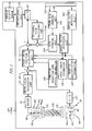
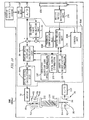
- Fig. 1 shows a camera system 190 (including an objective lens 190a and a vibration reduction apparatus) having an optical vibration reduction mechanism.
- an image vibration is reduced in directions of two axes, that is, the horizontal and vertical axes.
- Fig. 1 shows only a one-axis part of the optical vibration reduction mechanism.
- An angular velocity sensor 10 detects a vibration of the camera system 190 as an angular velocity utilizing a Coriolis force or the like.
- An amplification unit 20 amplifies an output of the angular velocity sensor 10.
- a low-pass filter may be added to reduce high-frequency noise in the sensor output.
- An A/D conversion unit 30 converts an output of the amplification unit 20 to digital angular velocity data.
- a reference value calculation unit 40 extracts low-frequency components from the angular velocity data that is output from the A/D conversion unit 30, and estimates an angular velocity reference value (i.e., angular velocity data in a stationary state that is free of a vibration). Further, the reference value calculation unit 40 corrects the reference value using a motion vector feedback path (described later).
- a target drive position calculation unit 50 calculates a true angular velocity as a cause of an image vibration by subtracting the reference value from the angular velocity data.
- the target drive position calculation unit 50 calculates an optical axis angle of the objective lens 190a by integrating the true angular velocity.
- the target drive position calculation unit 50 determines a target drive position on the basis of the optical axis angle.
- the target drive position is the position of a optical vibration reduction system 100 for canceling out a displacement of an object image in a state that the objective lens 190a has the above optical axis angle.
- the target drive position calculation unit 50 uses focal length information 120, shooting magnification information 130, and optical information 140 of the optical vibration reduction system 100.
- the focal length information 120 is information that is obtained when necessary from an encoder output of a zoom ring of the objective lens 190a.
- the shooting magnification information 130 is information that is obtained when necessary from a lens position of the objective lens 190a and an AF driving mechanism.
- a position detection unit 90 detects a position of the optical vibration reduction system 100.
- the position detection unit 90 is equipped with an infrared LED 92, a PSD (position-sensitive detector (or device)) 98, and a slit plate 94.
- Light emitted from the infrared LED 92 passes through a slit hole 96 of the slit plate 94 that is attached to a lens barrel 102 of the optical vibration reduction system 100, and is thereby converted to a narrow light beam, which reaches the PSD 98.
- the PSD 98 outputs a signal that represents a reception position of the light beam. This signal is converted to digital data by an A/D conversion unit 110, whereby position data of the optical vibration reduction system 100 is obtained.
- a drive signal calculation unit 60 calculates a deviation between the position data and the target drive position and calculates a drive signal in accordance with the deviation.
- a drive signal is calculated by a PID control in which a proportionality term, an integration term, and a differentiation term of the deviation are added together with a prescribed ratio.
- a driver 70 causes a drive current corresponding to the calculated drive signal (digital signal) to flow through a driving mechanism 80.
- the driving mechanism 80 is composed of a yoke 82, a magnet 84, and a coil 86.
- the coil 86 is fixed to the lens barrel 102 of the optical vibration reduction system 100 and is disposed in a magnetic circuit that is formed by the yoke 82 and the magnet 84.
- the optical vibration reduction system 100 can be moved perpendicularly to the optical axis by causing the drive current of the driver 70 to flow through the coil 86.
- the optical vibration reduction system 100 is part of the image forming optical system of the objective lens 190a.
- An image vibration of an object image can be suppressed by shifting the image forming position of the object image by moving the optical vibration reduction system 100 to the target drive position.
- the imaging surface of the image sensor 150 is disposed in the image space of the objective lens 190a.
- the image sensor 1 50 shoots an object image formed on the imaging surface.
- the shot image is displayed on a monitor screen (not shown) and output to a motion vector detection unit 160.
- the motion vector detection unit 160 detects a motion vector including a residual vibration by detecting a motion of shot images in the time-axis direction.
- a motion vector conversion unit 170 converts the motion vector so that it is expressed in the same scale as the reference value using the focal length information 120 and the shooting magnification information 130.
- a resulting motion vector is converted by a gain changing unit 220 (feedback control unit) to a feedback vector, which is fed back to the reference value of the reference value calculation unit 40.
- the gain changing unit 220 changes a feedback gain G in accordance with information on a frame rate F of shot images that is acquired by a frame rate changing unit 210.
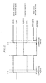
- Fig. 2 illustrates operation timing of optical vibration reduction.
- Fig. 3 is a flowchart showing a motion vector calculation procedure.
- Step S1 The image sensor 150 successively reads out shot images by thinning out read lines. These shot images are used for monitor display, exposure and focal point controls and a white balance adjustment control, moving image recording, etc.
- the frame rate changing unit 210 keeps the output signal level of the image sensor 150 in a prescribed, proper range by controlling the exposure time of a shot image on a frame-by-frame basis by increasing or decreasing the frame rate F of shot images in a range of 10-60 frames/sec.
- the exposure time per frame is set longer and the frame rate F of shot images are made lower.
- the exposure time per frame is set shorter and the frame rate F of shot images are made higher.
- the frame rate F of shot images varies halfway from a time interval Timg 1 to a time interval Timg2 as the luminance of an object varies.
- Step S2 The motion vector detection unit 160 determines a motion vector from, for example, an inter-frame difference between shot images.
- Examples of the motion vector detection method are a space/time gradient method and a block matching method.
- Step S3 The motion vector conversion unit 170 acquires focal length information 120 of the objective lens 190a.
- Step S4 The motion vector conversion unit 170 acquires shooting magnification information 130 of the objective lens 190a.
- Step S5 A motion vector that is output from the motion vector detection unit 160 is information on a displacement on the image surface. Therefore, the motion vector conversion unit 170 converts the motion vector so as to be expressed in the same scale (angular velocity scale) as the reference value.
- V' Z ⁇ tan -1 [V/ ⁇ f( 1 + ⁇ ) 2 ⁇ ] ⁇ Z ⁇ [V/ ⁇ f( 1 + ⁇ ) 2 ⁇ ]
- V is the motion vector before the conversion
- V' is the motion vector after the conversion
- f the focal length
- ⁇ the shooting magnification
- Z is a constant corresponding to the pixel interval of the image sensor 150.
- the above motion vector calculation processing is completed after a delay of a calculation time Tcal from each shooting time point.
- Step S6 The gain changing unit 220 acquires information on a current frame rate F from the frame rate changing unit 210.
- the gain changing unit 220 determines a feedback gain G corresponding to this frame rate F according to a prescribed conversion formula or a corresponding relationship. The details of the conversion formula or the corresponding relationship will be described later.
- Step S7 The gain changing unit 220 calculates a feedback vector GV' by multiplying the motion vector V' that is output from the motion vector conversion unit 170 by the feedback gain G.
- Step S8 The gain changing unit 220 updates, to the latest feedback vector GV' that was calculated at step S7, a feedback vector that it holds for reference value correction. After completion of the update operation, the gain changing unit 220 causes the process to return to step S1.
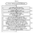
- Fig. 4 is a flowchart showing a control operation for the optical vibration reduction.
- Step S11 The A/D conversion unit 30 A/D-converts an angular velocity output of the angular velocity sensor 10 at a sampling interval Topt.
- Step S12 The reference value calculation unit 40 estimates a reference value Wo of angular velocity data obtained by the A/D conversion by subjecting it to moving averaging and low-pass filter processing.
- a corrected reference value Wo' has an error
- a residual vibration occurs in a shot image that has been subjected to the vibration reduction.
- the error in the reference value Wo' is decreased by detecting the residual vibration in the form of a motion vector V' and feeding back it to the reference value according to Equation (2).
- the motion vector V' decreases gradually.
- the reference value Wo' becomes a value that correctly includes a drift output or a DC offset of the angular velocity sensor 10.
- the target drive position and the reference value are updated at the sampling interval Topt which is shorter than the shooting interval Timg (see Fig. 2).
- a new motion vector cannot be used every time the reference value is corrected. Therefore, it is preferable to correct the reference value using one motion vector V' repeatedly until the next motion vector is acquired.
- Step S 14 The target drive position calculation unit 50 calculates true angular velocity data, which is a cause of an image vibration, by subtracting the corrected reference value Wo' from the angular velocity data that is output from the A/D conversion unit 30.
- Step S15 The target drive position calculation unit 50 calculates a displacement of the optical axis angle of the objective lens 190a by integrating the true angular velocity data.
- the target drive position calculation unit 50 calculates, from this optical axis angle value, a position of the optical vibration reduction system 100 (i.e., target drive position) that is necessary for canceling out a displacement of the image forming position of the object image.
- Step S16 The drive signal calculation unit 60 acquires information on the target drive position from the target drive position calculation unit 50 and controls the optical vibration reduction system 100 to follow the target drive position.
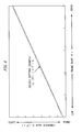
- a solid-line curve shown in Fig. 5 represents a first example of setting of a feedback gain G characteristic.
- the horizontal axis represents the frame rate F and the vertical axis represents the feedback gain G.
- the feedback gain G characteristic represented by the solid-line curve of Fig. 5 is set by an experiment or a simulation (calculation) according to the following procedure:
- the feedback gain G varies approximately in proportion to the frame rate F in a range where the frame rate F is relatively high (see Fig. 5). This makes it possible to cancel out a variation (increase or decrease) of the motion vector V' that is in inverse proportion to the frame rate F and to thereby keep the feedback vector GV' stable. As a result, even if the frame rate F decreases in a state that an image drift exists, the loop gain of the motion vector V' does not become too large and over-correction of the reference value is prevented, whereby the reference value is caused to converge more quickly.
- the feedback gain G characteristic is such that its curve is gentler as the frame rate F decreases.
- the probability that an image vibration is shot at positions excluding peak positions becomes higher, in which case a detected width of the image vibration is smaller than a true value.
- the curve of the feedback gain G characteristic of Fig. 5 decreases so as to cancel out such a reduction in detection sensitivity.
- an insufficient loop gain of the motion vector V' that is caused by the lowering of the frame rate F is compensated for and the speed of convergence of the reference value can be increased.
- the frame rate F varies halfway from F1 to F2 because the object luminance varies during a vibration reduction operation.
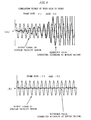
- Figs. 6[A] and 6[B] show a comparative example in which the feedback gain is fixed to G2 (> G1) irrespective of the frame rate variation.
- G2 > G1
- the apparent signal level of the motion vector V' increases and hence the feedback amount becomes excessive.
- the reference value is over-corrected as shown in Fig. 6[A] and finally diverges.
- Figs. 7[A] and 7[B] show an example in which the feedback gain G is changed as the frame rate F is varied from F1 to F2.
- the gains G1 and G2 are ones obtained by referring to the feedback gain G characteristic of Fig. 5. Changing the feedback gain G in this manner makes it possible to keep the reference value at a proper level stably.
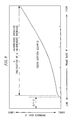
- a solid line Fig. 8 represents a second example of setting of a feedback gain G characteristic.
- the feedback gain G varies approximately in proportion to the frame rate F in a range where the frame rate F is sufficiently high.
- This proportional relationship between the frame rate F and the feedback gain G can cancel out a phenomenon that the motion signal varies in inverse proportion to the frame rate F.
- the feedback gain G of Equation (5) finally reaches the lower limit gain b instead of zero. That is, even if the frame rate F becomes very low, the lowering of the feedback gain G stops at the lower limit gain b.
- the setting of the lower limit gain b can compensate for a phenomenon that as the frame rate F decreases the feedback amount of the motion signal becomes insufficient because ends (peak positions) of an image vibration are not detected.
- a solid-line curve shown in Fig. 9 represents a third example of setting of a feedback gain G characteristic.
- This characteristic is based on the characteristic of the first setting example (Fig. 5) and is different from the latter in that a portion where the frame rate F is very low is replaced by a characteristic G ⁇ 0.
- the feedback gain G is forcibly set at zero. Setting the feedback gain G at zero in this manner makes it possible to prevent mixing of a low-reliability motion signal into the reference value and to thereby prevent lowering of the anti-vibration performance.
- the feedback gain G varies approximately in proportion to the frame rate F with the proportionality constant a.
- This approximately proportional relationship between the frame rate F and the feedback gain G can suppress a phenomenon that the motion signal varies in inverse proportion to the frame rate F in a state that an image drift occurs.
- the feedback gain G of Equation (5) finally reaches the lower limit gain b instead of zero. That is, even if the frame rate F becomes very low, the lowering of the feedback gain G stops at the lower limit gain b and excessive lowering of the feedback gain G can be prevented.
- the setting of the lower limit gain b can compensate for a phenomenon that as the frame rate F decreases the feedback amount of the motion signal becomes insufficient because ends (peak positions) of an image vibration are not detected.
- Fig. 10 shows a camera system 390 (including a vibration reduction apparatus) having a vibration reduction mechanism. Units and components having the same ones in the first embodiment (Fig. 1) will not be described below redundantly.
- the camera system 390 is equipped with a control unit 320 and a feedback suppression unit (feedback control unit) 330.
- the control unit 320 controls operation of the image sensor 150 and the feedback suppression unit 330.
- the feedback suppression unit 330 feeds back a motion vector to the reference value of the reference value calculation unit 40 while adjusting its feedback amount.
- a range implemented by a microprocessor 500 is indicated by a broken line in Fig. 10.
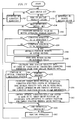
- Fig. 11 is a flowchart showing a control operation for the vibration reduction.
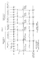
- Fig. 12 illustrates the timing of a motion vector feedback operation.
- Step S51 The control unit 320 judges the state of a main switch (not shown) of the camera system 390.
- control unit 320 causes the process to move to step S52.
- control unit 320 causes the process to move to step S53.
- Step S52 The control unit 320 stops the driving of the vibration reduction system according to the following procedure:
- control unit 320 After stopping the driving according to the above procedure, the control unit 320 causes the process to return to step S51.
- Step S53 When detecting the on-state of the main switch, the control unit 320 starts supplying power to the angular velocity sensor 10 etc. An angular velocity signal of the angular velocity sensor 10 is converted to digital data by the A/D conversion unit 30 at a prescribed sampling interval.
- Step S54 The control unit 320 judges the state of a half-depression switch (not shown) of the camera system 390.
- control unit 320 causes the process to move to step S51.
- control unit 320 causes the process to move to step S55.
- Step S55 The reference value calculation unit 40 estimates a reference value Wo of angular velocity data obtained by the A/D conversion by subjecting it to moving averaging and low-pass filter processing.
- Step S56 An interrupt occurs every time a new motion vector is calculated by the motion vector detection unit 160, and the motion vector values are updated.
- the motion vector detection unit 160 calculates a motion vector according to the following procedure:
- Step S57 The control unit 320 judges whether the vibration reduction is under driving or under suspension.
- control unit 320 causes the process to move to step S61.
- control unit 320 causes the process to move to step S58.
- Step S58 The control unit 320 measures an elapsed time from a start of driving for the vibration reduction and judges whether a prescribed suppression period has elapsed.
- control unit 320 causes the process to move to step S59.
- control unit 320 causes the process to move to step S60.
- the suppression period be one of the following periods:
- Step S59 The control unit 320 suppresses the feedback amounts of motion vectors during the suppression period.
- Step S60 The reference value calculation unit 40 feeds back, to the reference value Wo, a motion vector B that has been processed by the feedback suppression unit 330.
- Step S61 The target drive position calculation unit 50 calculates true angular velocity data, which is a cause of an image vibration, by subtracting a corrected reference value Wo' from angular velocity data that is output from the A/D conversion unit 30.
- Step S62 The target drive position calculation unit 50 makes a panning judgment.
- the panning judgment whether or not the camera system 390 is moving continuously in one direction is judged on the basis of the angular velocity data.
- the method of the panning judgment is not limited to this method; for example, the panning judgment may be made on the basis of motion vectors.
- step S63 If a judgment result "panning" is produced, the process moves to step S63.
- step S64 if a judgment result "panning" is not produced, the process moves to step S64.
- Step S63 The camera system 390 is panning. Therefore, the target drive position calculation unit 50 stops the driving of the optical vibration reduction system in the panning direction by keeping the target drive position constant. The process moves to step S66 with the driving of the optical vibration reduction system stopped.
- Step S64 The camera system 390 is not in a panning state. Therefore, the following vibration reduction operation is performed.
- the target drive position calculation unit 50 calculates an inclination angle of the optical axis of the objective lens 390a by integrating the true angular velocity data.
- the target drive position calculation unit 50 calculates a position (i.e., target drive position) of the optical vibration reduction system 100 that is necessary for canceling out a displacement of the image forming position of the object image.
- Step S65 The drive signal calculation unit 60 acquires information on the target drive position from the target drive position calculation unit 50, and calculates a deviation between the target drive position and a current position of the optical vibration reduction system 100 that is acquired from the position detection unit 90.
- the drive signal calculation unit 60 outputs a drive signal for canceling out the deviation.
- the driver 70 generates a drive current from the drive signal and causes it to flow through the driving mechanism 80. Because of this drive control, the optical vibration reduction system 100 is caused to follow the target drive position.
- Step S66 The control unit 320 judges the state of a full-depression switch (not shown) of the camera system 390.
- control unit 320 causes the process to return to step S51.
- control unit 320 causes the process to move to step S67.
- Step S67 The control unit 320 shoots a still image by driving the image sensor 150 while continuing the above vibration reduction. After completion of this shooing operation, the control unit 320 causes the process to return to step S51.
- the image sensor 150 sequentially outputs shot images Im1-Im8 at a shooting interval 1/FR.
- the motion vector detection unit 160 sequentially outputs motion vectors V1-V7; that is, the motion vector detection unit 160 captures immediately preceding two frames of shot images and outputs each motion vector after a lapse of a calculation waiting time DLY.
- driving for the vibration reduction is started after the output of the shot image lm2.
- the vibration-reduced shot image lm3 is output after a lapse of a time T1 from the start of the driving for the vibration reduction.
- the motion vector V1 reflects a camera shake or the like that occurred before the vibration reduction's taking effect.
- the motion vector V2 reflects a transitional variation of the vibration that bridges periods before and after the start of the driving for the vibration reduction.
- the motion vector V3 and the following motion vectors reflect a residual vibration occurring in the vibration reduction state.
- the period from the time point t1 (or t4) of the start of the driving for the vibration reduction to the acquisition of the motion vector V3 that reflects the residual vibration is equal to (T1 + DLY + 1 /FR).
- suppressing the feedback amount of each motion vector at least during the period (T1 + DLY + 1 /FR) makes it possible to prevent a large image motion occurring before the start of the driving for the vibration reduction from being mixed into the reference value and to thereby prevent the reference value from being disordered.
- the above-mentioned time T1 varies every time depending on the timing of the start of driving for the vibration reduction.
- the maximum value 1 /FR that the time T1 can take may be employed as a safety value instead of the time T1.
- a motion vector V4 that reflects a residual vibration can be obtained reliably by waiting for a lapse of a constant period (DLY + 2/FR).
- Figs. 14[A]-14[C] are graphs obtained by computer simulations and showing reference value pull-in operations. Advantages of setting the suppression period will be described below with reference to Figs. 14[A]-14[C].
- Fig. 14[A] shows a case that no suppression period is set. That is, feeding-back of motion vectors are started immediately after a start of driving for the vibration reduction.
- the reference value instantaneously deviates to a large extent due to motion vectors that are produced before the start of the driving for the vibration reduction.
- pulling-in of the reference value takes long time.
- the advantages of the vibration reduction are not obtained and the vibration is made worse contrary to the intention.
- Fig. 14[B] shows a case that the feedback amount is suppressed in the period from a start of driving for the vibration reduction to a lapse of the waiting time DLY from it.
- a motion vector reflects a transitional variation that bridges periods before and after the start of the driving for the vibration reduction. Therefore, also in this case, the reference value deviates and pulling-in of the reference value takes long time. During the reference value pull-in period, the advantages of the vibration reduction are not obtained and the vibration is made worse contrary to the intention.
- Fig. 14[C] shows a case that the suppression period is set at (DLY + 2/FR).
- a motion vector has small values reflecting a residual vibration of the vibration reduction.
- the reference values does not deviate much and the reference value pull-in time can be shortened very much. The advantages of the vibration reduction can be obtained quickly.
- the feedback path of the second embodiment is superior in the fundamental performance of the control system and is expected to provide a stable and proper control response.
- a motion vector is generated on the basis of shot images of the image sensor 150.
- shot images may be generated by performing photoelectric conversion by means of a divisional photometric mechanism, a focal point detection mechanism, a colorimetric mechanism, or a finder mechanism of a camera system.
- the invention can be implemented in a (silver-halide) film camera or a single-lens reflex electronic camera by generating a motion vector from such shot images.
- the invention can be applied to a type of camera in which optical vibration reduction is performed continuously while continuous shooting is performed.
- the objective lens and the camera system may be integral with each other. Alternatively, they may be detachable from each other. In the latter case, the block for generating a motion signal may be provided in either the objective lens or the camera system.
- the block for generating a motion signal is provided in the camera system and the block for converting a motion signal to a signal in the same scale as the reference value is provided in the objective lens.
- an angular velocity is detected as a vibration detection signal.
- the invention is not limited to such a case; it is satisfactory to detect a vibration component that enables estimation of a displacement of the image forming position of an object image.
- it is satisfactory to detect, as a vibration detection signal, acceleration, angular acceleration, centrifugal force, or inertial force that acts on the camera system.
- the vibration reduction is performed by shifting or tilting a light beam (light image) of the objective lens.
- the invention is not limited to such a case.
- the vibration reduction may be performed by shifting the image sensor.
- a motion vector is detected from two frames of shot images.
- the invention is not limited to such a case.
- a motion vector may be detected from an image flow in one frame.
- a motion vector may be detected by comparing three or more frames of shot images with each other.
- the feedback amount of a motion signal may be controlled by using both of the frame rate and the suppression period.
- the frame rate or periods before and after a start of vibration reduction are monitored as an analytical condition of a motion signal and the feedback amount of a motion signal is changed in accordance with a difference in the analytical condition.
- the analytical condition is not limited to the above ones.
- the feedback amount of a motion signal may be suppressed adaptively by detecting, from the analytical condition, a situation that motion signals are disordered or increase unduly. This kind of operation can also realize a vibration reduction apparatus that is less prone to be influenced by a variation (disorder) of motion signals.
- the suppression of the feedback amount may be canceled at any time after a lapse of the suppression period.
Landscapes
- Engineering & Computer Science (AREA)
- Multimedia (AREA)
- Signal Processing (AREA)
- Studio Devices (AREA)
- Control Of Position Or Direction (AREA)
Applications Claiming Priority (4)
| Application Number | Priority Date | Filing Date | Title |
|---|---|---|---|
| JP2004170380 | 2004-06-08 | ||
| JP2004170380A JP4595394B2 (ja) | 2004-06-08 | 2004-06-08 | ブレ補正装置、およびカメラシステム |
| JP2004248984 | 2004-08-27 | ||
| JP2004248984A JP4556560B2 (ja) | 2004-08-27 | 2004-08-27 | ブレ補正装置、およびカメラシステム |
Publications (2)
| Publication Number | Publication Date |
|---|---|
| EP1605691A2 true EP1605691A2 (de) | 2005-12-14 |
| EP1605691A3 EP1605691A3 (de) | 2007-04-18 |
Family
ID=34981262
Family Applications (1)
| Application Number | Title | Priority Date | Filing Date |
|---|---|---|---|
| EP05012157A Withdrawn EP1605691A3 (de) | 2004-06-08 | 2005-06-06 | Vibrationreduzierungsvorrichtung mit Rückkopplungspfad für Bewegungssignal und Kamerasystem |
Country Status (2)
| Country | Link |
|---|---|
| US (1) | US7522188B2 (de) |
| EP (1) | EP1605691A3 (de) |
Cited By (3)
| Publication number | Priority date | Publication date | Assignee | Title |
|---|---|---|---|---|
| EP1816857A2 (de) * | 2006-02-01 | 2007-08-08 | Sony Corporation | Verfahren und Gerät zur Kompensation von Signalverzerrungen einer Bildaufnahme, Bildaufnahmeverfahren und -gerät |
| EP2187626A1 (de) | 2008-11-14 | 2010-05-19 | Canon Kabushiki Kaisha | Bildaufnahmevorrichtung und zugehöriges Steuerungsverfahren |
| CN102289130A (zh) * | 2010-06-03 | 2011-12-21 | 安森美半导体贸易公司 | 环路增益调整电路 |
Families Citing this family (20)
| Publication number | Priority date | Publication date | Assignee | Title |
|---|---|---|---|---|
| JP5061444B2 (ja) * | 2005-09-20 | 2012-10-31 | ソニー株式会社 | 撮像装置及び撮像方法 |
| JP4916513B2 (ja) * | 2006-07-20 | 2012-04-11 | パナソニック株式会社 | 撮像装置 |
| TWI423665B (zh) * | 2006-10-10 | 2014-01-11 | Pentax Ricoh Imaging Co Ltd | 角速度偵測設備 |
| US8395672B2 (en) * | 2007-07-13 | 2013-03-12 | Panasonic Corporation | Imaging device that detects inclination of image and apparatus in a rolling direction |
| JP4982341B2 (ja) * | 2007-11-30 | 2012-07-25 | オンセミコンダクター・トレーディング・リミテッド | 撮像装置の防振制御回路 |
| JP5183518B2 (ja) * | 2008-03-11 | 2013-04-17 | キヤノン株式会社 | 像振れ補正装置およびそれを備える光学機器、撮像装置 |
| JP5178250B2 (ja) * | 2008-03-11 | 2013-04-10 | キヤノン株式会社 | 像ブレ補正装置およびそれを備える光学機器、撮像装置、像ブレ補正装置の制御方法 |
| CN101645641B (zh) * | 2008-08-08 | 2012-09-05 | 鸿富锦精密工业(深圳)有限公司 | 致动器 |
| JP5810307B2 (ja) * | 2010-05-10 | 2015-11-11 | パナソニックIpマネジメント株式会社 | 撮像装置 |
| JP5600516B2 (ja) * | 2010-08-09 | 2014-10-01 | キヤノン株式会社 | 撮像装置 |
| JP5572031B2 (ja) | 2010-08-09 | 2014-08-13 | キヤノン株式会社 | 撮像装置及びその制御方法 |
| US8488010B2 (en) * | 2010-09-21 | 2013-07-16 | Hewlett-Packard Development Company, L.P. | Generating a stabilized video sequence based on motion sensor data |
| JP5959850B2 (ja) * | 2011-12-27 | 2016-08-02 | キヤノン株式会社 | 撮像装置及びその制御方法 |
| KR101436984B1 (ko) * | 2012-10-04 | 2014-09-04 | 한국기계연구원 | 공작기계 진동 저감 장치 및 방법 |
| JP2014176034A (ja) * | 2013-03-12 | 2014-09-22 | Ricoh Co Ltd | 映像伝送装置 |
| JP6165052B2 (ja) * | 2013-12-26 | 2017-07-19 | キヤノン株式会社 | 振れ補正装置、それを有する撮像装置、振れ補正方法、およびプログラム |
| KR20160062379A (ko) * | 2014-11-25 | 2016-06-02 | 삼성전기주식회사 | 필터 전처리 회로 및 광학 이미지 안정화 모듈 |
| JP2019106655A (ja) * | 2017-12-14 | 2019-06-27 | ルネサスエレクトロニクス株式会社 | 半導体装置および電子機器 |
| JP2020148999A (ja) * | 2019-03-15 | 2020-09-17 | キヤノン株式会社 | 制御装置、撮像装置、レンズ装置、制御方法、および、プログラム |
| JP2023040890A (ja) * | 2021-09-10 | 2023-03-23 | キヤノン株式会社 | 像ブレ抑制装置およびその制御方法 |
Citations (2)
| Publication number | Priority date | Publication date | Assignee | Title |
|---|---|---|---|---|
| JPH10145662A (ja) | 1996-11-15 | 1998-05-29 | Canon Inc | 撮像装置、記憶媒体、レンズユニット及びぶれ補正装置 |
| JPH10322585A (ja) | 1997-05-20 | 1998-12-04 | Canon Inc | 撮像装置及び撮像システム |
Family Cites Families (10)
| Publication number | Priority date | Publication date | Assignee | Title |
|---|---|---|---|---|
| JP3052250B2 (ja) | 1990-01-05 | 2000-06-12 | キヤノン株式会社 | 画像ぶれ補正装置 |
| JP2803072B2 (ja) * | 1990-10-18 | 1998-09-24 | 富士写真フイルム株式会社 | 手振れ補正装置 |
| JP3860844B2 (ja) * | 1994-05-10 | 2006-12-20 | オリンパス株式会社 | 手ぶれ検出装置及び手ぶれ検出方法 |
| JPH09322057A (ja) * | 1996-05-28 | 1997-12-12 | Canon Inc | 撮像装置 |
| US6573930B2 (en) * | 1996-11-15 | 2003-06-03 | Canon Kabushiki Kaisha | Image pickup apparatus for storing, reading-out and processing a signal during predetermined time periods |
| US6429895B1 (en) | 1996-12-27 | 2002-08-06 | Canon Kabushiki Kaisha | Image sensing apparatus and method capable of merging function for obtaining high-precision image by synthesizing images and image stabilization function |
| US6734901B1 (en) * | 1997-05-20 | 2004-05-11 | Canon Kabushiki Kaisha | Vibration correction apparatus |
| JP4436442B2 (ja) * | 1997-12-19 | 2010-03-24 | キヤノン株式会社 | 撮像装置及びカメラユニット及びレンズユニット |
| JP3466895B2 (ja) * | 1997-12-12 | 2003-11-17 | キヤノン株式会社 | 振れ補正装置、撮像装置、撮像システム、カメラユニット、及びレンズユニット |
| US20050018051A1 (en) | 2003-07-25 | 2005-01-27 | Nikon Corporation | Shooting lens having vibration reducing function and camera system for same |
-
2005
- 2005-06-06 US US11/144,657 patent/US7522188B2/en not_active Expired - Fee Related
- 2005-06-06 EP EP05012157A patent/EP1605691A3/de not_active Withdrawn
Patent Citations (2)
| Publication number | Priority date | Publication date | Assignee | Title |
|---|---|---|---|---|
| JPH10145662A (ja) | 1996-11-15 | 1998-05-29 | Canon Inc | 撮像装置、記憶媒体、レンズユニット及びぶれ補正装置 |
| JPH10322585A (ja) | 1997-05-20 | 1998-12-04 | Canon Inc | 撮像装置及び撮像システム |
Cited By (10)
| Publication number | Priority date | Publication date | Assignee | Title |
|---|---|---|---|---|
| EP1816857A2 (de) * | 2006-02-01 | 2007-08-08 | Sony Corporation | Verfahren und Gerät zur Kompensation von Signalverzerrungen einer Bildaufnahme, Bildaufnahmeverfahren und -gerät |
| EP1816857A3 (de) * | 2006-02-01 | 2008-11-05 | Sony Corporation | Verfahren und Gerät zur Kompensation von Signalverzerrungen einer Bildaufnahme, Bildaufnahmeverfahren und -gerät |
| US8009872B2 (en) | 2006-02-01 | 2011-08-30 | Sony Corporation | Taken-image signal-distortion compensation method, taken-image signal-distortion compensation apparatus, image taking method and image-taking apparatus |
| CN101123684B (zh) * | 2006-02-01 | 2012-02-01 | 索尼株式会社 | 拍摄图像信号失真补偿方法和装置及图像拍摄方法和装置 |
| USRE45231E1 (en) | 2006-02-01 | 2014-11-04 | Sony Corporation | Taken-image signal-distortion compensation method, taken-image signal-distortion compensation apparatus, image taking method and image-taking apparatus |
| EP2187626A1 (de) | 2008-11-14 | 2010-05-19 | Canon Kabushiki Kaisha | Bildaufnahmevorrichtung und zugehöriges Steuerungsverfahren |
| US8279290B2 (en) | 2008-11-14 | 2012-10-02 | Canon Kabushiki Kaisha | Blur correcting image pickup apparatus and control method |
| CN101742098B (zh) * | 2008-11-14 | 2013-07-24 | 佳能株式会社 | 摄像装置及其控制方法 |
| CN102289130A (zh) * | 2010-06-03 | 2011-12-21 | 安森美半导体贸易公司 | 环路增益调整电路 |
| CN102289130B (zh) * | 2010-06-03 | 2014-03-05 | 半导体元件工业有限责任公司 | 环路增益调整电路 |
Also Published As
| Publication number | Publication date |
|---|---|
| US7522188B2 (en) | 2009-04-21 |
| EP1605691A3 (de) | 2007-04-18 |
| US20050270380A1 (en) | 2005-12-08 |
Similar Documents
| Publication | Publication Date | Title |
|---|---|---|
| US7522188B2 (en) | Vibration reduction apparatus having feedback path for motion signal, and camera system | |
| US7932926B2 (en) | Shooting lens having vibration reducing function and camera system for same | |
| EP1507408B1 (de) | Objektiv mit Funktion zur Verminderung von Vibrationen und zugehöriges Kamerasystem | |
| EP2200276B1 (de) | Abbildungsvorrichtung für optische Stabilisierung während des Schwenkens der Kamera | |
| CN101742098B (zh) | 摄像装置及其控制方法 | |
| KR101497534B1 (ko) | 흔들림 보정장치, 흔들림 보정제어 방법, 및 촬상장치 및 그 제어 방법 | |
| US10812722B2 (en) | Imaging apparatus, shake correction method, lens unit, and body unit | |
| JP4419466B2 (ja) | 撮影レンズ、およびカメラシステム | |
| US10250808B2 (en) | Imaging apparatus and control method therefor | |
| JP4869579B2 (ja) | ブレ補正装置、およびカメラシステム | |
| JP4360147B2 (ja) | 撮影レンズ、およびカメラシステム | |
| JP4556560B2 (ja) | ブレ補正装置、およびカメラシステム | |
| US10873701B2 (en) | Image pickup apparatus and control method thereof | |
| JP4415596B2 (ja) | 撮影レンズ、およびカメラシステム | |
| JP2005351984A (ja) | ブレ補正装置、およびカメラシステム | |
| US11736819B2 (en) | Imaging apparatus and image scaling timing in relation to thinned-out frame | |
| US20210075976A1 (en) | Imaging apparatus | |
| JP2005141207A (ja) | ブレ補正装置、およびカメラシステム | |
| JP4400322B2 (ja) | ブレ補正装置、およびカメラシステム | |
| WO2019203147A1 (ja) | 撮像装置 | |
| JP4329133B2 (ja) | 手振れ補正機能付き撮影装置及び手振れ補正方法 | |
| JP2009063664A (ja) | 撮影装置 |
Legal Events
| Date | Code | Title | Description |
|---|---|---|---|
| PUAI | Public reference made under article 153(3) epc to a published international application that has entered the european phase |
Free format text: ORIGINAL CODE: 0009012 |
|
| AK | Designated contracting states |
Kind code of ref document: A2 Designated state(s): AT BE BG CH CY CZ DE DK EE ES FI FR GB GR HU IE IS IT LI LT LU MC NL PL PT RO SE SI SK TR |
|
| AX | Request for extension of the european patent |
Extension state: AL BA HR LV MK YU |
|
| PUAL | Search report despatched |
Free format text: ORIGINAL CODE: 0009013 |
|
| AK | Designated contracting states |
Kind code of ref document: A3 Designated state(s): AT BE BG CH CY CZ DE DK EE ES FI FR GB GR HU IE IS IT LI LT LU MC NL PL PT RO SE SI SK TR |
|
| AX | Request for extension of the european patent |
Extension state: AL BA HR LV MK YU |
|
| 17P | Request for examination filed |
Effective date: 20071015 |
|
| AKX | Designation fees paid |
Designated state(s): AT BE BG CH CY CZ DE DK EE ES FI FR GB GR HU IE IS IT LI LT LU MC NL PL PT RO SE SI SK TR |
|
| 17Q | First examination report despatched |
Effective date: 20080222 |
|
| RAP1 | Party data changed (applicant data changed or rights of an application transferred) |
Owner name: NIKON CORPORATION |
|
| RAP1 | Party data changed (applicant data changed or rights of an application transferred) |
Owner name: NIKON CORPORATION |
|
| GRAP | Despatch of communication of intention to grant a patent |
Free format text: ORIGINAL CODE: EPIDOSNIGR1 |
|
| INTG | Intention to grant announced |
Effective date: 20190924 |
|
| STAA | Information on the status of an ep patent application or granted ep patent |
Free format text: STATUS: THE APPLICATION IS DEEMED TO BE WITHDRAWN |
|
| 18D | Application deemed to be withdrawn |
Effective date: 20200205 |