EP1605162A2 - Kompakte Verdichtereinheit - Google Patents
Kompakte Verdichtereinheit Download PDFInfo
- Publication number
- EP1605162A2 EP1605162A2 EP05011262A EP05011262A EP1605162A2 EP 1605162 A2 EP1605162 A2 EP 1605162A2 EP 05011262 A EP05011262 A EP 05011262A EP 05011262 A EP05011262 A EP 05011262A EP 1605162 A2 EP1605162 A2 EP 1605162A2
- Authority
- EP
- European Patent Office
- Prior art keywords
- piston
- groove
- compact
- ring seal
- cylinder chamber
- Prior art date
- Legal status (The legal status is an assumption and is not a legal conclusion. Google has not performed a legal analysis and makes no representation as to the accuracy of the status listed.)
- Granted
Links
Images


Classifications
-
- B—PERFORMING OPERATIONS; TRANSPORTING
- B29—WORKING OF PLASTICS; WORKING OF SUBSTANCES IN A PLASTIC STATE IN GENERAL
- B29C—SHAPING OR JOINING OF PLASTICS; SHAPING OF MATERIAL IN A PLASTIC STATE, NOT OTHERWISE PROVIDED FOR; AFTER-TREATMENT OF THE SHAPED PRODUCTS, e.g. REPAIRING
- B29C73/00—Repairing of articles made from plastics or substances in a plastic state, e.g. of articles shaped or produced by using techniques covered by this subclass or subclass B29D
- B29C73/16—Auto-repairing or self-sealing arrangements or agents
- B29C73/166—Devices or methods for introducing sealing compositions into articles
-
- F—MECHANICAL ENGINEERING; LIGHTING; HEATING; WEAPONS; BLASTING
- F04—POSITIVE - DISPLACEMENT MACHINES FOR LIQUIDS; PUMPS FOR LIQUIDS OR ELASTIC FLUIDS
- F04B—POSITIVE-DISPLACEMENT MACHINES FOR LIQUIDS; PUMPS
- F04B35/00—Piston pumps specially adapted for elastic fluids and characterised by the driving means to their working members, or by combination with, or adaptation to, specific driving engines or motors, not otherwise provided for
- F04B35/04—Piston pumps specially adapted for elastic fluids and characterised by the driving means to their working members, or by combination with, or adaptation to, specific driving engines or motors, not otherwise provided for the means being electric
-
- F—MECHANICAL ENGINEERING; LIGHTING; HEATING; WEAPONS; BLASTING
- F04—POSITIVE - DISPLACEMENT MACHINES FOR LIQUIDS; PUMPS FOR LIQUIDS OR ELASTIC FLUIDS
- F04B—POSITIVE-DISPLACEMENT MACHINES FOR LIQUIDS; PUMPS
- F04B35/00—Piston pumps specially adapted for elastic fluids and characterised by the driving means to their working members, or by combination with, or adaptation to, specific driving engines or motors, not otherwise provided for
- F04B35/06—Mobile combinations
-
- B—PERFORMING OPERATIONS; TRANSPORTING
- B29—WORKING OF PLASTICS; WORKING OF SUBSTANCES IN A PLASTIC STATE IN GENERAL
- B29L—INDEXING SCHEME ASSOCIATED WITH SUBCLASS B29C, RELATING TO PARTICULAR ARTICLES
- B29L2030/00—Pneumatic or solid tyres or parts thereof
Definitions
- the present invention relates to a compact simplified compressor apparatus which has a high performance and excellent reliability, and can be easily activated even under a low temperature, and more particularly to a compact simplified compressor apparatus which can be preferably employed as a flat tire emergency repair kit filling an air together with a sealing agent in a flat tire so as to allow an emergency travel.
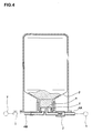
- kit S for repairing the flat tire in an emergent manner for example, as shown in Figs. 3 and 4, there has been a structure constituted by a compact simplified compressor apparatus 1, and a seal pump-up apparatus 3 having a sealing can 2 filled with a puncture seal agent.
- the kit S can charge an internal pressure after feeding the sealing agent in the sealing can 2 to a flat tire T.
- the compact simplified compressor apparatus 1 is connected to the seal pump-up apparatus 3 by a hose 4A having a joint 5a, and the seal pump-up apparatus 3 is connected to a valve of the tire T by a hose 4B having a joint 5b. Further, as shown in Fig. 4, a high-pressure air from the compact simplified compressor apparatus 1 is supplied to a sealed chamber f formed in a lower lid c of the sealing can 2, and breaks the lower lid c due to the pressure. Thereafter, the sealing agent is supplied to the tire T by opening a switch valve i in a downstream side. The tire can be pumped up at a predetermined internal pressure by continuously operating the compact simplified compressor apparatus 1 even after the supply of the sealing agent is finished.
- the puncture hole is closed by the sealing agent by immediately running for about ten minutes. Thereafter, the emergency repair is finished by again inspecting the internal pressure.
- a check valve j is provided in a leading end of the hose 4A, thereby preventing the sealing agent from flowing backward.
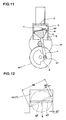
- the compact compressor is provided with a motor m, a wheel m1 driven at a reduced speed by the motor m so as to rotate, a crank k attached to the wheel m1, a rod n pivoted by a crank pin k1 of the crank k, and a piston q attached to a leading end portion of the rod n.
- the rod n and the piston q are integrally formed, and a ring seal s such as an O-ring or the like fitted to a peripheral groove y of an outer peripheral surface qs of the piston q is arranged in the piston q.
- the piston q integrally works with the rod n in accordance with a rotation of the crank k so as to vertically slide within a cylinder chamber u. Further, when the piston q moves downward, an intake valve v provided in an upper surface of the piston q is opened so as to suck an air. Further, when moving upward, the intake valve v is closed so as to compress the air within the cylinder chamber u, and can discharge the compressed air from an air supply port z in an upper end.
- the piston q becomes in a state q1 of being perpendicular to a center line of the cylinder chamber u at a top dead center and a bottom dead center of the piston q as shown by a solid line in Fig. 12.
- the piston q becomes in a maximum inclined state q2 of being inclined to the center line of the cylinder chamber u to the maximum.
- a gap g2 between an outer peripheral surface qs of the piston q and an inner peripheral surface u1 of the cylinder chamber u in the maximum inclined state q2 becomes larger than a gap g1 in the perpendicular state q1.
- Reference symbol d2 denotes a longer diameter of the oval in the maximum inclined state q2.
- An object of the present invention is to provide a compact simplified compressor apparatus which can secure a sufficient seal effect even in the case that a piston is inclined with respect to a cylinder chamber and the case that the apparatus is used under a low temperature environment, can increase a pump efficiency while intending a weight saving and a compact structure, and can improve a reliability.
- a compact simplified compressor apparatus comprising:
- a compact simplified compressor apparatus 1 in accordance with the present embodiment is employed in a puncture emergency repairing kit S shown in Figs. 3 and 4.
- the kit S repairs a flat tire in an emergent manner, and makes it possible to run up to a tire repair facility such as an automobile repair shop or the like.
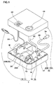
- the compact simplified compressor apparatus 1 is provided with a rotating shaft 11 rotationally driven by a motor M, a compact compressor 10 activated by the rotating shaft 11, an air feeding means 18 for feeding a high-pressure air from the compact compressor 10 to the tire, and a power source plug 19 for supplying an electricity to the motor M.
- the motor M, the rotating shaft 11, the compact compressor 10 and the air feeding means 18 are received within a case 20 constituted by housings 20A and 20B which can be separated into upper and lower parts.
- a hose 4A provided with a joint 5a connectable to a seal pump-up apparatus 3 (shown in Figs. 3 and 4) in a leading end is connected to the air feeding means 18.
- An electric cord 6A provided with the power source plug 19 in a leading end is connected to the motor M.
- An on-off switch 22 provided in an upper surface of the upper housing 20A is interposed in the electric cord 6A.
- a DC motor activated by a 12V direct-current power source of an automobile is used as the motor M.
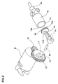
- the compact compressor 10 and the air feeding means 18 are assembled in a frame 23 so as to construct an integral air discharging unit 24.
- the frame 23 is provided with a support wall 23B rotatably supporting an inner end portion of the rotating shaft 11.
- a gear 22 engaging with a pinion 21 of an output shaft in the motor M and a crank 12 with balance are fixed to an outer end portion of the rotating shaft 11 so as to be integrally rotatable.
- the motor M is also fixed by bolt to the support wall 23B.
- the rotation of the motor M is reduced to about one third to one eighth by a speed reduction mechanism constituted by the pinion 21 and the gear 22 so as to be transmitted to the rotating shaft 11.
- the support wall 23B of the frame 23 is provided with a covering portion 23A surrounding an operating portion such as the speed reduction mechanism, the crank 12, a rod 13 and the like, for protection.
- the compact compressor 10 is provided with the crank 12 fixed to the rotating shaft 11, the rod 13 rotatably coupled to the crank 12 via a crank pin 26, a piston 14 provided in the leading end of the rod 13, and a cylinder 16 receiving the piston 14 so as to freely reciprocate forward and backward.
- the rod 13 and the piston 14 are molded as one integral component and formed of fiber reinforced plastics (FRP) so as to be formed firmly and light in weight.
- a ring seal 30 is attached to an outer peripheral surface 14a of the piston 14.
- an intake valve 31 constituted by a ventilation hole 31A passing forward and backward through the piston 14, thereby communicating with a cylinder chamber 15, and a valve body 31B closing the ventilation hole 31A.
- the valve body 31B is constituted by a thin plate made of an elastic material such as a rubber, a synthetic resin, a metal or the like, or a thin plate energized by a coil spring, in the present embodiment, is attached to a front end of the piston 14, and can close an opening portion of the ventilation hole 31A with a spring property.
- the cylinder 16 is fixed to the frame 23.
- the piston 14 can reciprocate forward and backward from a bottom dead center (shown in Fig. 5B) at which the piston 14 is farthest apart from a bottom wall 15w of the cylinder chamber 15 to a top dead center (not shown) at which the piston 14 is closest to the bottom wall 15w, in accordance with the rotation of the crank 12. Further, at a time of moving forward (compression), the intake valve 31 is closed, whereby compressing the air in the cylinder chamber 15 and generating the high-pressure air. At a time of moving backward (sucking the air), the intake valve 31 is opened, thereby sucking the air into the cylinder chamber 15.
- the piston 14 and the rod 13 are integrally formed, at an intermediate position at a time of the compression reaching the top dead center from the bottom dead center, as shown in Fig. 5C, the piston 14 becomes in a maximum inclined state q2a inclined to one side to the maximum, with respect to center of an axis of the cylinder chamber 15. Further, at an intermediate position at a time of the intake reaching the bottom dead center from the top dead center, as shown in Fig. 5A, the piston 14 becomes in a maximum inclined state q2b inclined to the other side to the maximum, with respect to center of the axis of the cylinder chamber 15.
- a gap G between an outer peripheral surface 14a of the piston 14 and an inner peripheral surface 15a of the cylinder chamber 15 is increased in comparison with a gap G in the state of the top dead center and the bottom dead center.
- the ring seal 30 is fitted to a peripheral groove 33 provided in the outer peripheral surface 14a of the piston 14.
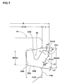
- the peripheral groove 33 is provided with a groove bottom surface 33A which is in parallel to a central axis of the piston 14, and groove side surfaces 33B and 33C, each of which extends from an end edge in a rod side and an end edge in an opposite rod side, as shown in Fig. 7.
- Each of the groove side surfaces 33B and 33C is inclined in a direction in which a groove width is increased toward the outer peripheral surface 14a.
- Angles ⁇ 1 and ⁇ 2 which the groove side surfaces 33B and 33C form with respect to a radial line perpendicular to the groove bottom surface 33A are preferably within a range between 5° and 20°.
- angles ⁇ 1 and ⁇ 2 may be made equal to each other, or the angle ⁇ 1 of the groove side surface 33B in the rod side may be made smaller so as to increase a resisting force of the piston 14 at a time of the compression.
- the angles ⁇ 1 and ⁇ 2 are both set to 10°.
- a width W33a of the groove bottom surface 33A of the peripheral groove 33 is preferably within a range between 0.9 and 3.6 mm, and further preferably within a range between 1.5 and 2.5 mm. In the present embodiment, it is set to 1.8 mm.
- a groove depth H33 from the outer peripheral surface 14a is preferably within a range between 1.0 and 4.0 mm, and further preferably within a range between 1.6 and 2.3 mm. In the present embodiment, it is set to 2.0 mm.
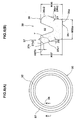
- the ring seal 30 mentioned above is constituted by a circular ring body as shown in Fig. 6(A). Further, as a horizontal cross section including a central axis of the ring seal 30 is shown in Fig. 6 (B), the ring seal 30 comprises a base portion 35 formed in an approximately rectangular cross sectional shape and having a flat base surface 35a seating on the rod side groove side surface 33B of the peripheral groove 33, and inner and outer lip portions 36 and 37, each extending from the base portion 35 toward radially inside and outside so as to be opened toward the opposite rod side. Accordingly, the V-shaped groove 32 is formed between the lip portions 36 and 37. In this case, the base surface 35a forms a right angle with respect to the central axis of the ring seal 30, in the present embodiment.
- the inner lip portion 36 and the outer lip portion 37 are formed so as to have an approximately equal thickness to each other in a root portion. Further, in a free state of the ring seal 30, an inner peripheral surface 36s (a side surface in an opposite side to the V-shaped groove 32) of the inner lip portion 36 is formed by an inclined surface 36c1 which is inclined at an angle ⁇ 1 with respect to a line perpendicular to the base surface 35a, and a convex circular arc shaped curved surface 36c2 in a leading end side.
- an outer peripheral surface 37s (a side surface in an opposite side to the V-shaped groove 32) of the outer lip portion 37 is formed by an inclined surface 37c1 which is inclined at an angle ⁇ 2 with respect to the line perpendicular to the base surface 35a, and an inclined surface 37c2 in a leading end side which intersects the inclined surface 37c1 at an angle ⁇ between 80 and 140°.
- a height H37c of the inclined surfaces 37c1 and 37c2 from a leading end of an intersecting point 37c is set to a range which is 5 to 15 % of an entire height H37 of the outer lip portion 37.
- the angles ⁇ 1 and ⁇ 2 are set to a range between 10° and 40°, and preferably a range between 15 and 30°. In the present embodiment, the angles ⁇ 1 and ⁇ 2 are both set to 22°.
- a width W35a of the base surface 35a is set to be equal to a length extending along the side surface of the rod side groove side surface 33B of the peripheral groove 33, and the base surface 35a is seated on the grove side surface 33B, as shown in Fig. 7. Further, it is preferable that the inner lip portion 36 is brought into contact with the groove bottom surface 33A of the peripheral groove 33 in a state in which the base surface 35a is seated. Accordingly, the angle ⁇ 1 is set to a range which is equal to or more than the angle ⁇ 1 of the peripheral groove 33 and is equal to or less than ( ⁇ 1 + 15°), thereby preventing the outer lip portion 37 from collapsing onto an inner side in a radial direction.
- an entire height H36 of the inner lip portion 36 is set larger in a range between 2 and 10 % than the width of the portion of the peripheral groove 33.
- the groove side surface 33C in the opposite rod side of the peripheral groove 33 is inclined to the opposite rod side at the angle ⁇ 2 mentioned above, and the outer lip portion 37 is also inclined to an outer side in the radial direction at the angle ⁇ 2 with respect to the base surface 35a.
- the height H37 is made equal to the height H36 of the inner lip portion 36
- the leading end of the outer lip portion 37 can be apart from the groove side surface 33C in the opposite rod side at a distance N (shown in Fig. 7). Accordingly, even in the case that the outer lip portion 37 is bent inward in the radial direction, it is possible to prevent a collision with the groove side surface 33C in the opposite rod side.
- the intersecting point 37c of the outer lip portion 37 protrudes to an outer side in the radial direction at the distance L from the outer peripheral surface 14a of the piston 14.
- an outer diameter R of the outer lip portion 37 is obtained by adding a diameter d14a of the outer peripheral surface 14a of the piston 14 to a double of the distance L, in accordance with the following expression.
- R d14a + 2•L
- the angle ⁇ between the inclined surfaces 37c1 and 37c2 of the outer lip portion 37 is preferably set to a range between 90 and 130° in a free state, and is preferably set such that a bisector of the angle ⁇ is perpendicular to the inner peripheral surface 15a of the cylinder chamber 15, in the inserted state. Accordingly, the contact with the inner peripheral surface 15a can be equalized at a time of reciprocating, and it is possible to improve a smoothness of a slide motion.
- the outer diameter d14a of the outer peripheral surface 14a of the piston 14 can secure the gap G between the outer peripheral surface 14a of the piston 14 and the inner peripheral surface 15a of the cylinder chamber 15 even in the maximum inclined state q2 of the piston 14, whereby the collision is not generated. Accordingly, the outer diameter d14a of the outer peripheral surface 14a is set while taking into consideration a thickness of the piston 14, a chamfer of the peripheral edge portion and the like (Fig. 8A).
- an outline b obtained by connecting the intersecting point 37c of the ring seal 30 and a contact point with which the inner peripheral surface 15a of the cylinder chamber 15 is brought into contact forms an oval.
- the outer diameter R of the outer lip portion 37 is set to 1.02 to 1.15 times of the longer diameter d2. Therefore, even in the maximum inclined state q2, as shown in Fig. 8(A), a leak of the compressed air is reduced.
- the outer diameter R is preferably between 1.03 and 1.08 times of the longer diameter d2.
- the outer lip portion 37 is elastically deformed in the radial direction even in the case that the gap G is changed on the basis of the incline of the piston 14, whereby it is possible to seal the gap G.
- the compressed air within the cylinder chamber 15 is applied to the outer lip portion 37.
- the pressure of the compressed air is applied in a direction of pressing out the outer lip portion 37 to an outer side in the radial direction, thereby improving a contact property with the cylinder chamber 15. Therefore, it is possible to prevent an evagination of the outer lip portion 37 and an air leak from the gap.
- the ring seal 30 is formed by using a rubber material such as a hydrogenated nitrile rubber (HNBR), a nitrile rubber (NBR), a butadiene rubber (BR), a styrene-butadiene rubber (SBR), a chloroprene rubber (CR), an ethylene propylene rubber (EPDM) and the like.
- HNBR hydrogenated nitrile rubber
- NBR nitrile rubber
- BR butadiene rubber
- SBR styrene-butadiene rubber
- CR chloroprene rubber
- EPDM ethylene propylene rubber
- the hydrogenated nitrile rubber (HNBR) and the nitrile rubber (NBR) are excellent in an elasticity and a heat resistance, it is possible to stably achieve a sealing property over a long period of time even in a wide temperature environment between -30°C and 80°C, and they can be preferably used in the ring seal 30 having an approximately V-shaped cross section and having the inner and outer lip portions 36 and 37.
- a rubber hardness (durometer A hardness) is set, for example, in a range between 65° and 80°.
- the rubber hardness 74° is employed.
- a lower limit value of the rubber hardness is preferably equal to or more than 70°
- an upper limit value is preferably equal to or less than 75°. In this case, if it is more than 80°, a frictional resistance of the ring seal 30 becomes too large, and on the contrary, if it is less than 65°, the seal pressure with respect to the inner peripheral surface 15a of the cylinder chamber 15 comes short so as to cause a pressure reduction of the high-pressure air.
- a grease such as a synthetic hydrocarbon oil (PAO), a mineral oil, a fluorine-contained synthetic oil, a diester, a polyol ester, a polyglycol, a phenyl ether, a silicone or the like is used as a lubricant.
- PAO synthetic hydrocarbon oil
- the synthetic hydrocarbon oil (PAO) achieves an excellent durability, for example, in a temperature range from a low temperature of - 30°C to a high temperature of 80°C. Accordingly, it can be preferably employed as the grease for the compact simplified compressor apparatus 1 for the puncture emergency repair kit S used in the wide temperature range.
- the air discharging unit 24 is integrally structured, as mentioned above, by incorporating the compact compressor 10 and the air feeding means 18 into the frame 23.
- the air feeding means 18 forms a compressed air inlet 15e provided in the bottom wall 15w of the cylinder chamber 15, and a surrounding wall 43 forming a surge tank 42 communicating with the inlet 15e, as shown in Fig. 5(A).
- the surge tank 42 absorbs a pulsation of the high-pressure air from the cylinder chamber 15.
- an attaching port 43a for connecting the hose 4A In the surrounding wall 43, as shown in Figs. 1 and 5 (A), there are formed an attaching port 43a for connecting the hose 4A, an attaching port 43b for connecting the relief valve 17, and an attaching port 43c for connecting the hose 4C communicating with a pressure gauge 44 provided in the upper housing 20A.
- the relief valve 17 is provided with a conical valve seat 50a formed in an air inflow side of the attaching port 43b, a screw portion 50b formed in an air outflow side, a valve shaft 51 having a seal brought into contact with the valve seat 50a, an adjusting screw 52 screwed with the screw portion 50b, and a pressing spring 53 pressing the valve shaft 51 to the valve seat 50a, as shown in Fig. 9(A). Further, as shown in Fig. 9 (B), a seal strength is adjusted by screwing forward and backward the adjusting screw 52, and an internal pressure of the surge tank 42 gets over a predetermined value, whereby the valve is opened and the internal pressure is relieved.
- the relief valve 17 when the pressure gets over a set relief pressure (350 kPa in the present embodiment) of the relief valve 17, the relief valve 17 is opened, whereby it is possible to prevent the members from the compact compressor 10 to the tire T from being damaged due to an overpressure, and it is possible to set a tire filling internal pressure.
- a set relief pressure 350 kPa in the present embodiment
- the pressing spring 53 is formed by using a stainless steel including SUS304 or the like, a piano wire, a spring steel, a tool steel or the like.
- a stainless steel including SUS304 or the like, a piano wire, a spring steel, a tool steel or the like.
- the stainless steel it is preferable to employ a hardened stainless steel. Accordingly, it is possible to reduce a deterioration of the spring force applied to a repeated load, and it is possible to maintain a relief pressure constant even by using a long time use.
- the relief valve 17 is placed about 10 cm apart from the bottom wall 5w of the cylinder 16, it is possible to prevent the pressing spring 53 from being deteriorated due to the heat applied from the cylinder 16 which is going to be a high temperature.
- the power source plug 19 is connected to a cigar lighter socket communicating with a battery of a motor vehicle, in the present embodiment.
- the power source plug 19 is provided with a plug main body 55 to which the electric cord 6A is connected, a + side terminal pin 56 conducted with the electric cord 6A and provided in a leading end of the plug main body 55, and a - side terminal connection spring 57 provided in an inner side of the + side terminal pin 56, as shown in Fig. 10(A).
- The-side terminal connection spring 57 is provided with a plurality of (four in the present embodiment) leg pieces 57b bending perpendicularly from a coupling piece 57a and extending in parallel to a central axis of the plug main body 55.
- Each of the leg pieces 57b is provided with a terminal portion 57c protruding from a surface of the plug main body 55 so as to be exposed, and forms a V-shaped portion 57c1 bent in a V-shaped cross sectional shape along a width center line of the leg piece 57b in the terminal portion 57c, as shown in Fig. 10(C).
- a top portion of the V-shaped portion 57c1 is curved in a convex circular arc shape in a direction of protruding from the surface of the plug main body 55.
- the V-shaped portion 57c1 of the - side terminal connection spring 57 is smoothly pressure contacted with the inner peripheral surface of the cigar lighter socket at a time of inserting the power source plug 19 to the cigar lighter socket. Accordingly, it is possible to make an operation such as an insertion to the cigar lighter socket and a drawing therefrom, a rotation for fixing a torsion of the electric cord 6A and the like smooth, and it is possible to prevent the power source plug from falling out.
- the - side terminal connection spring 57 is formed by using a phosphor bronze, a copper, a stainless steel or the like, however, particularly in the - side terminal connection spring 57 using the phosphor bronze metal plated by Ni on the basis of JISC5191, an electric conductivity is high, a high strength and excellent spring property and abrasion resistance can be achieved, a strong chemical corrosion is obtained, and it is possible to optimize a resistance at a time of drawing. Accordingly, this structure is preferable.
- a pump performance is compared between the case (examples 1 and 2) of using the V-shaped ring seal shown in Figs. 4 to 6 in accordance with the present invention, and the case (a comparative example 1) using a conventional solid O-ring.
- the ring seal in accordance with the example 1 employs an NBR (a rubber hardness 74°), and the ring seal in accordance with the example 2 employs a silicone rubber.
- the compressors using the ring seals are operated under two kinds of environments of 25°C and -30°C, and a time until the internal pressure of 250 kPa is filled in the tire having a tire size of 225/60R16 is measured.
- the ring seal used in the examples 1 and 2 is structured such that the width W33a of the groove bottom surface 33A of the peripheral groove 33 is 1.8 mm, the width W33d of the opening portion is 2.5 mm, a ratio R/d2 is 1.05 and the maximum angle of incline of the piston is 20°.
- Ring seal Example 1 Example 2 Comparative Example 1 Ring seal shape V shape V shape O type Ring seal material NBR Silicone rubber NBR Pressure increasing performance 25°C 5' 56" 6'05" 5' 57" -30°C 6' 43" 8'21" 8'42"
- a durability test is executed by using compressors in accordance with reference examples 1 to 3 respectively employing the synthetic hydrocarbon oil, the mineral oil and the fluorine synthetic oil as the grease, on the basis of the specification in Table 2, and repeating an operation (five minutes) and a stop (twenty five minutes) at 250 kPa until the total test time becomes 100 hours, under two kinds of environments of 80°C and -30°C. As a result, no damage is recognized in the reference example 1 under any environments of high temperature and low temperature.
Landscapes
- Engineering & Computer Science (AREA)
- Mechanical Engineering (AREA)
- General Engineering & Computer Science (AREA)
- Compressor (AREA)
- Compressors, Vaccum Pumps And Other Relevant Systems (AREA)
- Sealing With Elastic Sealing Lips (AREA)
Applications Claiming Priority (2)
| Application Number | Priority Date | Filing Date | Title |
|---|---|---|---|
| JP2004163526 | 2004-06-01 | ||
| JP2004163526A JP4392292B2 (ja) | 2004-06-01 | 2004-06-01 | 小型簡易コンプレッサ装置 |
Publications (3)
| Publication Number | Publication Date |
|---|---|
| EP1605162A2 true EP1605162A2 (de) | 2005-12-14 |
| EP1605162A3 EP1605162A3 (de) | 2006-11-29 |
| EP1605162B1 EP1605162B1 (de) | 2008-07-16 |
Family
ID=34936895
Family Applications (1)
| Application Number | Title | Priority Date | Filing Date |
|---|---|---|---|
| EP05011262A Active EP1605162B1 (de) | 2004-06-01 | 2005-05-24 | Kompakte Verdichtereinheit |
Country Status (5)
| Country | Link |
|---|---|
| US (1) | US7547201B2 (de) |
| EP (1) | EP1605162B1 (de) |
| JP (1) | JP4392292B2 (de) |
| CN (1) | CN100368684C (de) |
| DE (1) | DE602005008137D1 (de) |
Cited By (17)
| Publication number | Priority date | Publication date | Assignee | Title |
|---|---|---|---|---|
| WO2008035191A2 (en) * | 2006-09-21 | 2008-03-27 | Tek Global S.R.L. | Kit, comprising an improved compressor assembly, for repairing and inflating inflatable articles |
| EP2353848A1 (de) * | 2010-02-09 | 2011-08-10 | Wen-San Jhou | Vorrichtung zum Versiegeln und Aufpumpen eines aufpumpbaren Objekts |
| WO2012094413A2 (en) * | 2011-01-04 | 2012-07-12 | Bell Automotive Products, Inc. | Portable tire inflator and reflective device |
| EP2497627A1 (de) * | 2009-11-04 | 2012-09-12 | Sumitomo Rubber Industries, Ltd. | Punktionsreparaturkit |
| EP2497629A1 (de) * | 2009-11-04 | 2012-09-12 | Sumitomo Rubber Industries, Ltd. | Reifenflickset |
| EP2497628A1 (de) * | 2009-11-04 | 2012-09-12 | Sumitomo Rubber Industries, Ltd. | Reifenflickset |
| WO2013120261A1 (zh) | 2012-02-16 | 2013-08-22 | Jhou Wen-San | 车载用空气压缩机装置 |
| WO2013143778A1 (de) * | 2012-03-28 | 2013-10-03 | Continental Reifen Deutschland Gmbh | Vorrichtung zum abdichten und aufpumpen eines aufpumpbaren objekts |
| US8925594B2 (en) | 2011-01-04 | 2015-01-06 | Bell Automotive Products, Inc. | Portable tire inflator and reflective device |
| EP3090864A1 (de) * | 2013-01-25 | 2016-11-09 | Illinois Tool Works, Inc. | Vorrichtung zur erzeugung eines drucks |
| CN107244195A (zh) * | 2017-05-22 | 2017-10-13 | 宁波高新区甬航工业设计有限公司 | 一种便携式并带有照明功能的打气筒 |
| EP3418567A1 (de) * | 2017-06-21 | 2018-12-26 | Walmsley Developments Pty Ltd | Tragbare pumpe |
| US10731637B2 (en) | 2015-07-27 | 2020-08-04 | Walmsley Developments Pty Ltd | Portable pump |
| EP3698991A4 (de) * | 2018-12-26 | 2020-11-25 | Pacific Industrial Co., Ltd. | Füllverfahren für flüssigen brennstoff und schmiermittel |
| EP4074969A4 (de) * | 2019-12-11 | 2023-12-27 | NTN Corporation | Wellendichtung |
| US11890900B2 (en) | 2018-12-26 | 2024-02-06 | Pacific Industrial Co., Ltd. | Transmitter |
| WO2024032855A1 (de) * | 2022-08-09 | 2024-02-15 | Continental Reifen Deutschland Gmbh | Kompressorsysteme für pannenhilfesets |
Families Citing this family (41)
| Publication number | Priority date | Publication date | Assignee | Title |
|---|---|---|---|---|
| TWI235790B (en) * | 2004-02-29 | 2005-07-11 | Wen-Shan Chou | Miniature simple air filling device |
| CN2851637Y (zh) * | 2005-06-17 | 2006-12-27 | 杨琪 | 便携式轮胎充气机 |
| DE102005060320A1 (de) * | 2005-12-16 | 2007-06-21 | Continental Aktiengesellschaft | Kompressoreinheit |
| JP5004672B2 (ja) * | 2006-05-31 | 2012-08-22 | 株式会社日立産機システム | 揺動型圧縮機 |
| AU2007257159B2 (en) * | 2006-06-08 | 2013-08-22 | Larry Alvin Schuetzle | Reciprocating compressor or pump and a portable tool powering system including a reciprocating compressor |
| GB2439384B (en) * | 2006-06-19 | 2009-08-12 | Allan Hopkins | Pump Apparatus |
| US20090010774A1 (en) * | 2007-07-02 | 2009-01-08 | Fish Robert D | Air Compressor and Reservoir For Topping Off Low Pressure Tires |
| CN101429935B (zh) * | 2007-11-07 | 2012-03-07 | 周文三 | 空气压缩机的活塞体结构 |
| JP5230995B2 (ja) * | 2007-11-09 | 2013-07-10 | 周 文三 | 改良されたシールリングを有する空気圧縮機 |
| WO2009119317A1 (ja) * | 2008-03-25 | 2009-10-01 | 住友ゴム工業株式会社 | タイヤのパンク修理装置 |
| JP4369981B2 (ja) * | 2008-04-30 | 2009-11-25 | 住友ゴム工業株式会社 | コンプレッサ装置 |
| JP2010261556A (ja) * | 2009-05-11 | 2010-11-18 | Bridgestone Corp | 安全弁及びコンプレッサ |
| JP5285536B2 (ja) * | 2009-08-18 | 2013-09-11 | 周 文三 | 空気圧縮機 |
| IT1395661B1 (it) * | 2009-08-21 | 2012-10-16 | Tek Global Srl | Contenitore per un liquido sigillante e kit di riparazione comprendente tale contenitore |
| JP5285539B2 (ja) * | 2009-08-24 | 2013-09-11 | 住友ゴム工業株式会社 | コンプレッサ装置 |
| KR101187377B1 (ko) | 2010-03-03 | 2012-10-04 | 웬-산 초우 | 공기 주입식 타이어 수리용 공기 압축기 |
| JP5731799B2 (ja) * | 2010-11-10 | 2015-06-10 | 住友ゴム工業株式会社 | パンク修理キット |
| JP5353873B2 (ja) * | 2010-12-25 | 2013-11-27 | マックス株式会社 | 圧縮機の制御装置 |
| JP5374524B2 (ja) * | 2011-01-26 | 2013-12-25 | 住友ゴム工業株式会社 | コンプレッサ装置 |
| CN102619726B (zh) * | 2011-01-28 | 2015-08-05 | 周文三 | 空气压缩机 |
| CN104564605B (zh) * | 2011-01-28 | 2017-07-28 | 周文三 | 一种空气压缩机 |
| JP5681550B2 (ja) * | 2011-04-13 | 2015-03-11 | 住友ゴム工業株式会社 | コンプレッサ装置 |
| US20110252960A1 (en) * | 2011-04-27 | 2011-10-20 | Flight Medical Innovations Ltd. | Mechanical ventilator |
| US8733270B2 (en) * | 2011-11-28 | 2014-05-27 | Chi-Wen Chen | Pressure indication device of inflation machine |
| EP2918834B1 (de) * | 2012-10-26 | 2017-12-13 | Sumitomo Rubber Industries, Ltd. | Verdichter und diesen verwendendes reparaturkit für platte reifen |
| EP2955383B1 (de) * | 2013-02-07 | 2019-05-01 | Chou, Wen-san | Konstruktion eines luftkompressors |
| US9057656B2 (en) * | 2013-04-25 | 2015-06-16 | Chi-Wen Chen | Pressure indication device of inflation machine with safety pressure relief |
| DE102013105217A1 (de) * | 2013-05-22 | 2014-11-27 | Illinois Tool Works Inc. | Kompressor zum Erzeugen eines Druckmediums |
| CN103470471A (zh) * | 2013-08-05 | 2013-12-25 | 厉煊 | 一种便携式充气泵 |
| TW201507900A (zh) * | 2013-08-27 | 2015-03-01 | Active Tools Int Hk Ltd | 輪胎修補機之空壓機的汽缸機座 |
| GB201402528D0 (en) * | 2014-02-13 | 2014-04-02 | Delphi Int Operations Luxembourg Sarl | High pressure fuel pump |
| DE102014205071A1 (de) * | 2014-03-19 | 2015-09-24 | Continental Reifen Deutschland Gmbh | Vorrichtung zum Abdichten und Aufpumpen aufblasbarer Gegenstände |
| TWI575159B (zh) * | 2014-05-26 | 2017-03-21 | 周文三 | 可攜式打氣機設備組 |
| TWI577889B (zh) * | 2014-10-07 | 2017-04-11 | 周文三 | 改良之空氣壓縮機構造 |
| CN104454442B (zh) * | 2014-12-31 | 2018-03-06 | 东莞瑞柯电子科技股份有限公司 | 一种微型空压机 |
| JP5867637B1 (ja) | 2015-02-23 | 2016-02-24 | 横浜ゴム株式会社 | パンク修理液収容容器 |
| DE102015203970A1 (de) * | 2015-03-05 | 2016-09-08 | Continental Reifen Deutschland Gmbh | Tragbare Kompressor-Einrichtung |
| EP3329123A4 (de) * | 2015-09-02 | 2019-03-27 | Active Tools International (HK) Ltd. | Luftfüllvorrichtung und reifenreparaturmaschine damit |
| DE102016209302A1 (de) * | 2016-05-30 | 2017-12-14 | Continental Reifen Deutschland Gmbh | Verfahren zum Abdichten und Aufpumpen aufblasbarer Gegenstände |
| JP1572080S (de) * | 2016-10-03 | 2017-03-21 | ||
| US10933844B2 (en) * | 2018-06-21 | 2021-03-02 | Illinois Tool Works Inc. | Vehicle tire inflation compressor for powered data ports |
Citations (8)
| Publication number | Priority date | Publication date | Assignee | Title |
|---|---|---|---|---|
| US2081040A (en) * | 1932-06-17 | 1937-05-18 | J S Abercrombie | Packing |
| US4027816A (en) * | 1975-04-18 | 1977-06-07 | Bowen Tools, Inc. | Seal assembly |
| DE3319729A1 (de) * | 1982-06-04 | 1983-12-08 | Volvo Flymotor AB, 46181 Trollhättan | Kolbenringanordnung fuer hydraulikanwendungen, insbesondere fuer sehr hohe betriebsdrucke |
| WO1986004128A1 (en) * | 1985-01-11 | 1986-07-17 | The Secretary Of State For Trade And Industry In H | Piston and connecting rod combination |
| US5064359A (en) * | 1990-07-16 | 1991-11-12 | Ingersoll-Rand Company | Annular support for a seal for a tilt piston |
| US6152014A (en) * | 1989-03-17 | 2000-11-28 | Willimczik; Wolfhart | Rotary piston machines |
| JP3082724U (ja) * | 2001-06-15 | 2001-12-26 | 文三 周 | 空気圧縮機 |
| EP1358996A1 (de) * | 2002-05-03 | 2003-11-05 | Adam Opel Ag | Reifenreparatursystem |
Family Cites Families (22)
| Publication number | Priority date | Publication date | Assignee | Title |
|---|---|---|---|---|
| US2360731A (en) * | 1942-08-15 | 1944-10-17 | Maytag Co | Wedge-ring seal |
| US3040712A (en) * | 1959-04-17 | 1962-06-26 | Firco Inc | Cylinder, piston and rod assembly |
| DE2951112C2 (de) * | 1979-12-19 | 1983-10-13 | Messerschmitt-Bölkow-Blohm GmbH, 8000 München | Aus faserverstärktem Kunststoff gefertigte Pleuelstange für Kraftmaschinen |
| FR2532994B1 (fr) * | 1982-09-11 | 1988-02-26 | Becker Erich | Pompe a piston oscillant |
| DE3233854A1 (de) * | 1982-09-11 | 1984-03-15 | Erich 7812 Bad Krozingen Becker | Pendelkolbenpumpe |
| JPS62251568A (ja) * | 1986-04-24 | 1987-11-02 | Mitsubishi Rayon Co Ltd | 繊維強化樹脂製小型ピストンの製造方法 |
| US5092125A (en) * | 1987-10-29 | 1992-03-03 | Automotive Products Plc | Seal |
| KR920001704Y1 (ko) | 1989-11-15 | 1992-03-09 | 이상우 | 형광등용 안정기의 보호회로 |
| DE4339652C2 (de) * | 1992-12-17 | 2003-10-30 | Zf Sachs Ag | Hydraulisch betätigbare Ausrücker-Nehmerzylinder für eine Kraftfahrzeug-Reibungskupplung |
| US5509670A (en) * | 1994-10-28 | 1996-04-23 | The Texacone Company | Packing member with reduced friction |
| DE19518875A1 (de) * | 1995-05-23 | 1996-11-28 | Lothar Wanzke | Kolben mit Pleuelstange |
| DE19549592C5 (de) * | 1995-07-11 | 2006-12-14 | Sumitomo Rubber Industries Ltd., Kobe | Vorrichtung zum Abdichten und Aufpumpen von Reifen bei Pannen |
| JPH11325245A (ja) * | 1998-05-18 | 1999-11-26 | Aisin Seiki Co Ltd | スイングピストン |
| JP3802987B2 (ja) * | 1998-08-06 | 2006-08-02 | 自動車電機工業株式会社 | 携帯用電動エアーポンプ |
| JP2000238144A (ja) * | 1999-02-17 | 2000-09-05 | Sumitomo Rubber Ind Ltd | タイヤのシール・ポンプアップ装置 |
| US6189894B1 (en) * | 1999-04-19 | 2001-02-20 | The Texacone Company | Urethane packing member with improved geometric configuration |
| JP2001271744A (ja) * | 2000-03-24 | 2001-10-05 | Denso Corp | エアコンプレッサ |
| CN2526603Y (zh) * | 2001-08-20 | 2002-12-18 | 李勇涛 | 半装甲式密封装置 |
| DE10151542B4 (de) * | 2001-10-23 | 2006-12-28 | Carl Freudenberg Kg | Komplett-Kolben |
| DE60224302T2 (de) * | 2001-11-15 | 2008-12-18 | Even Honour International Ltd. | Vorrichtung zum abdichten und aufblasen eines aufblasbaren objekts |
| US7017914B1 (en) * | 2002-10-15 | 2006-03-28 | Dana Corporation | Piston assembly and method of manufacture |
| CN2592899Y (zh) * | 2002-12-11 | 2003-12-17 | 周文三 | 空气压缩机活塞体构造改良 |
-
2004
- 2004-06-01 JP JP2004163526A patent/JP4392292B2/ja active Active
-
2005
- 2005-05-24 DE DE602005008137T patent/DE602005008137D1/de active Active
- 2005-05-24 EP EP05011262A patent/EP1605162B1/de active Active
- 2005-05-31 US US11/139,620 patent/US7547201B2/en active Active
- 2005-06-01 CN CNB2005100732180A patent/CN100368684C/zh active Active
Patent Citations (8)
| Publication number | Priority date | Publication date | Assignee | Title |
|---|---|---|---|---|
| US2081040A (en) * | 1932-06-17 | 1937-05-18 | J S Abercrombie | Packing |
| US4027816A (en) * | 1975-04-18 | 1977-06-07 | Bowen Tools, Inc. | Seal assembly |
| DE3319729A1 (de) * | 1982-06-04 | 1983-12-08 | Volvo Flymotor AB, 46181 Trollhättan | Kolbenringanordnung fuer hydraulikanwendungen, insbesondere fuer sehr hohe betriebsdrucke |
| WO1986004128A1 (en) * | 1985-01-11 | 1986-07-17 | The Secretary Of State For Trade And Industry In H | Piston and connecting rod combination |
| US6152014A (en) * | 1989-03-17 | 2000-11-28 | Willimczik; Wolfhart | Rotary piston machines |
| US5064359A (en) * | 1990-07-16 | 1991-11-12 | Ingersoll-Rand Company | Annular support for a seal for a tilt piston |
| JP3082724U (ja) * | 2001-06-15 | 2001-12-26 | 文三 周 | 空気圧縮機 |
| EP1358996A1 (de) * | 2002-05-03 | 2003-11-05 | Adam Opel Ag | Reifenreparatursystem |
Cited By (26)
| Publication number | Priority date | Publication date | Assignee | Title |
|---|---|---|---|---|
| WO2008035191A2 (en) * | 2006-09-21 | 2008-03-27 | Tek Global S.R.L. | Kit, comprising an improved compressor assembly, for repairing and inflating inflatable articles |
| WO2008035191A3 (en) * | 2006-09-21 | 2008-05-29 | Tek Global Srl | Kit, comprising an improved compressor assembly, for repairing and inflating inflatable articles |
| EP2497628A4 (de) * | 2009-11-04 | 2014-04-30 | Sumitomo Rubber Ind | Reifenflickset |
| EP2497627A4 (de) * | 2009-11-04 | 2014-04-30 | Sumitomo Rubber Ind | Punktionsreparaturkit |
| EP2497627A1 (de) * | 2009-11-04 | 2012-09-12 | Sumitomo Rubber Industries, Ltd. | Punktionsreparaturkit |
| EP2497629A1 (de) * | 2009-11-04 | 2012-09-12 | Sumitomo Rubber Industries, Ltd. | Reifenflickset |
| EP2497628A1 (de) * | 2009-11-04 | 2012-09-12 | Sumitomo Rubber Industries, Ltd. | Reifenflickset |
| US8997801B2 (en) | 2009-11-04 | 2015-04-07 | Sumitomo Rubber Industries, Ltd. | Puncture repair kit |
| EP2497629A4 (de) * | 2009-11-04 | 2014-04-30 | Sumitomo Rubber Ind | Reifenflickset |
| EP2353848A1 (de) * | 2010-02-09 | 2011-08-10 | Wen-San Jhou | Vorrichtung zum Versiegeln und Aufpumpen eines aufpumpbaren Objekts |
| WO2012094413A3 (en) * | 2011-01-04 | 2012-10-26 | Bell Automotive Products, Inc. | Portable tire inflator and reflective device |
| US8925594B2 (en) | 2011-01-04 | 2015-01-06 | Bell Automotive Products, Inc. | Portable tire inflator and reflective device |
| WO2012094413A2 (en) * | 2011-01-04 | 2012-07-12 | Bell Automotive Products, Inc. | Portable tire inflator and reflective device |
| WO2013120261A1 (zh) | 2012-02-16 | 2013-08-22 | Jhou Wen-San | 车载用空气压缩机装置 |
| WO2013143778A1 (de) * | 2012-03-28 | 2013-10-03 | Continental Reifen Deutschland Gmbh | Vorrichtung zum abdichten und aufpumpen eines aufpumpbaren objekts |
| EP2830862B1 (de) * | 2012-03-28 | 2017-08-09 | Continental Reifen Deutschland GmbH | Vorrichtung zum abdichten und aufpumpen eines aufpumpbaren objekts |
| EP3090864A1 (de) * | 2013-01-25 | 2016-11-09 | Illinois Tool Works, Inc. | Vorrichtung zur erzeugung eines drucks |
| US10731637B2 (en) | 2015-07-27 | 2020-08-04 | Walmsley Developments Pty Ltd | Portable pump |
| CN107244195A (zh) * | 2017-05-22 | 2017-10-13 | 宁波高新区甬航工业设计有限公司 | 一种便携式并带有照明功能的打气筒 |
| EP3418567A1 (de) * | 2017-06-21 | 2018-12-26 | Walmsley Developments Pty Ltd | Tragbare pumpe |
| US10837433B2 (en) | 2017-06-21 | 2020-11-17 | Walmsley Developments Pty Ltd | Portable pump |
| EP3698991A4 (de) * | 2018-12-26 | 2020-11-25 | Pacific Industrial Co., Ltd. | Füllverfahren für flüssigen brennstoff und schmiermittel |
| US11279184B2 (en) | 2018-12-26 | 2022-03-22 | Pacific Industrial Co., Ltd. | Fuel solution introducing method and lubricant |
| US11890900B2 (en) | 2018-12-26 | 2024-02-06 | Pacific Industrial Co., Ltd. | Transmitter |
| EP4074969A4 (de) * | 2019-12-11 | 2023-12-27 | NTN Corporation | Wellendichtung |
| WO2024032855A1 (de) * | 2022-08-09 | 2024-02-15 | Continental Reifen Deutschland Gmbh | Kompressorsysteme für pannenhilfesets |
Also Published As
| Publication number | Publication date |
|---|---|
| EP1605162B1 (de) | 2008-07-16 |
| JP4392292B2 (ja) | 2009-12-24 |
| US20050265873A1 (en) | 2005-12-01 |
| US7547201B2 (en) | 2009-06-16 |
| EP1605162A3 (de) | 2006-11-29 |
| JP2005344570A (ja) | 2005-12-15 |
| CN1704584A (zh) | 2005-12-07 |
| CN100368684C (zh) | 2008-02-13 |
| DE602005008137D1 (de) | 2008-08-28 |
Similar Documents
| Publication | Publication Date | Title |
|---|---|---|
| EP1605162A2 (de) | Kompakte Verdichtereinheit | |
| TWI235790B (en) | Miniature simple air filling device | |
| EP2657007B1 (de) | Reparatursatz für platte reifen | |
| EP2918834B1 (de) | Verdichter und diesen verwendendes reparaturkit für platte reifen | |
| US20130011283A1 (en) | Air Compressor | |
| TW538197B (en) | Compressor device of high pressure compressor | |
| US6213725B1 (en) | Compressor having an improved piston | |
| EP1321499B1 (de) | Dichtungsmaterial zur Verwendung in Dichtelement für Kompressor und Kompressor enthaltend dasselbe | |
| US6280163B1 (en) | Spring blade intake valve for air compressor | |
| CN205876644U (zh) | 一种缸体导向微型增压式电动气泵 | |
| US20110076164A1 (en) | Air compressor having tilted piston | |
| CN101607390A (zh) | 电动压接工具设备 | |
| US20050265862A1 (en) | Pump | |
| CN113931833B (zh) | 阀座机构及微型电动隔膜泵 | |
| US20140023537A1 (en) | Air Pump Cylinder | |
| EP2320086B1 (de) | Luftkompressor mit Kippkolben | |
| CN211819843U (zh) | 充气泵 | |
| CN111059201B (zh) | 一种线性阻尼器 | |
| CN2849215Y (zh) | 低功耗的微型气压泵 | |
| CN216198856U (zh) | 泵体驱动机构及微型电动隔膜泵 | |
| CN217300803U (zh) | 一种二级空气压缩装置及其底座结构 | |
| TWM258186U (en) | Compact and simple air filling device | |
| CN219911740U (zh) | 钢氟复合硫化密封组件 | |
| CN214887544U (zh) | 一种气体增压装置 | |
| CN208664882U (zh) | 车用空调双向压缩机 |
Legal Events
| Date | Code | Title | Description |
|---|---|---|---|
| PUAI | Public reference made under article 153(3) epc to a published international application that has entered the european phase |
Free format text: ORIGINAL CODE: 0009012 |
|
| AK | Designated contracting states |
Kind code of ref document: A2 Designated state(s): AT BE BG CH CY CZ DE DK EE ES FI FR GB GR HU IE IS IT LI LT LU MC NL PL PT RO SE SI SK TR |
|
| AX | Request for extension of the european patent |
Extension state: AL BA HR LV MK YU |
|
| PUAL | Search report despatched |
Free format text: ORIGINAL CODE: 0009013 |
|
| AK | Designated contracting states |
Kind code of ref document: A3 Designated state(s): AT BE BG CH CY CZ DE DK EE ES FI FR GB GR HU IE IS IT LI LT LU MC NL PL PT RO SE SI SK TR |
|
| AX | Request for extension of the european patent |
Extension state: AL BA HR LV MK YU |
|
| RIC1 | Information provided on ipc code assigned before grant |
Ipc: F04B 35/06 20060101AFI20050704BHEP Ipc: F04B 33/00 20060101ALI20061024BHEP Ipc: F04B 53/14 20060101ALI20061024BHEP Ipc: B60C 23/10 20060101ALI20061024BHEP Ipc: B29C 73/16 20060101ALI20061024BHEP |
|
| 17P | Request for examination filed |
Effective date: 20061229 |
|
| 17Q | First examination report despatched |
Effective date: 20070205 |
|
| AKX | Designation fees paid |
Designated state(s): DE FR GB IT |
|
| GRAP | Despatch of communication of intention to grant a patent |
Free format text: ORIGINAL CODE: EPIDOSNIGR1 |
|
| GRAS | Grant fee paid |
Free format text: ORIGINAL CODE: EPIDOSNIGR3 |
|
| GRAA | (expected) grant |
Free format text: ORIGINAL CODE: 0009210 |
|
| AK | Designated contracting states |
Kind code of ref document: B1 Designated state(s): DE FR GB IT |
|
| REG | Reference to a national code |
Ref country code: GB Ref legal event code: FG4D |
|
| REF | Corresponds to: |
Ref document number: 602005008137 Country of ref document: DE Date of ref document: 20080828 Kind code of ref document: P |
|
| PLBE | No opposition filed within time limit |
Free format text: ORIGINAL CODE: 0009261 |
|
| STAA | Information on the status of an ep patent application or granted ep patent |
Free format text: STATUS: NO OPPOSITION FILED WITHIN TIME LIMIT |
|
| 26N | No opposition filed |
Effective date: 20090417 |
|
| REG | Reference to a national code |
Ref country code: FR Ref legal event code: PLFP Year of fee payment: 12 |
|
| REG | Reference to a national code |
Ref country code: FR Ref legal event code: PLFP Year of fee payment: 13 |
|
| REG | Reference to a national code |
Ref country code: FR Ref legal event code: PLFP Year of fee payment: 14 |
|
| PGFP | Annual fee paid to national office [announced via postgrant information from national office to epo] |
Ref country code: FR Payment date: 20210412 Year of fee payment: 17 Ref country code: IT Payment date: 20210412 Year of fee payment: 17 |
|
| PGFP | Annual fee paid to national office [announced via postgrant information from national office to epo] |
Ref country code: GB Payment date: 20210429 Year of fee payment: 17 |
|
| GBPC | Gb: european patent ceased through non-payment of renewal fee |
Effective date: 20220524 |
|
| PG25 | Lapsed in a contracting state [announced via postgrant information from national office to epo] |
Ref country code: FR Free format text: LAPSE BECAUSE OF NON-PAYMENT OF DUE FEES Effective date: 20220531 |
|
| PG25 | Lapsed in a contracting state [announced via postgrant information from national office to epo] |
Ref country code: GB Free format text: LAPSE BECAUSE OF NON-PAYMENT OF DUE FEES Effective date: 20220524 |
|
| P01 | Opt-out of the competence of the unified patent court (upc) registered |
Effective date: 20230510 |
|
| PG25 | Lapsed in a contracting state [announced via postgrant information from national office to epo] |
Ref country code: IT Free format text: LAPSE BECAUSE OF NON-PAYMENT OF DUE FEES Effective date: 20220524 |
|
| PGFP | Annual fee paid to national office [announced via postgrant information from national office to epo] |
Ref country code: DE Payment date: 20230331 Year of fee payment: 19 |