EP1604931A2 - Device for treating and/or conveying a web - Google Patents
Device for treating and/or conveying a web Download PDFInfo
- Publication number
- EP1604931A2 EP1604931A2 EP05104185A EP05104185A EP1604931A2 EP 1604931 A2 EP1604931 A2 EP 1604931A2 EP 05104185 A EP05104185 A EP 05104185A EP 05104185 A EP05104185 A EP 05104185A EP 1604931 A2 EP1604931 A2 EP 1604931A2
- Authority
- EP
- European Patent Office
- Prior art keywords
- web
- former
- movable
- transversely
- drive
- Prior art date
- Legal status (The legal status is an assumption and is not a legal conclusion. Google has not performed a legal analysis and makes no representation as to the accuracy of the status listed.)
- Granted
Links
Images


Classifications
-
- B—PERFORMING OPERATIONS; TRANSPORTING
- B65—CONVEYING; PACKING; STORING; HANDLING THIN OR FILAMENTARY MATERIAL
- B65H—HANDLING THIN OR FILAMENTARY MATERIAL, e.g. SHEETS, WEBS, CABLES
- B65H35/00—Delivering articles from cutting or line-perforating machines; Article or web delivery apparatus incorporating cutting or line-perforating devices, e.g. adhesive tape dispensers
- B65H35/02—Delivering articles from cutting or line-perforating machines; Article or web delivery apparatus incorporating cutting or line-perforating devices, e.g. adhesive tape dispensers from or with longitudinal slitters or perforators
-
- B—PERFORMING OPERATIONS; TRANSPORTING
- B65—CONVEYING; PACKING; STORING; HANDLING THIN OR FILAMENTARY MATERIAL
- B65H—HANDLING THIN OR FILAMENTARY MATERIAL, e.g. SHEETS, WEBS, CABLES
- B65H23/00—Registering, tensioning, smoothing or guiding webs
- B65H23/04—Registering, tensioning, smoothing or guiding webs longitudinally
- B65H23/26—Registering, tensioning, smoothing or guiding webs longitudinally by transverse stationary or adjustable bars or rollers
-
- B—PERFORMING OPERATIONS; TRANSPORTING
- B65—CONVEYING; PACKING; STORING; HANDLING THIN OR FILAMENTARY MATERIAL
- B65H—HANDLING THIN OR FILAMENTARY MATERIAL, e.g. SHEETS, WEBS, CABLES
- B65H45/00—Folding thin material
- B65H45/12—Folding articles or webs with application of pressure to define or form crease lines
- B65H45/22—Longitudinal folders, i.e. for folding moving sheet material parallel to the direction of movement
- B65H45/221—Longitudinal folders, i.e. for folding moving sheet material parallel to the direction of movement incorporating folding triangles
- B65H45/226—Positional adjustment of folding triangles
-
- B—PERFORMING OPERATIONS; TRANSPORTING
- B65—CONVEYING; PACKING; STORING; HANDLING THIN OR FILAMENTARY MATERIAL
- B65H—HANDLING THIN OR FILAMENTARY MATERIAL, e.g. SHEETS, WEBS, CABLES
- B65H2301/00—Handling processes for sheets or webs
- B65H2301/40—Type of handling process
- B65H2301/41—Winding, unwinding
- B65H2301/414—Winding
- B65H2301/4148—Winding slitting
-
- B—PERFORMING OPERATIONS; TRANSPORTING
- B65—CONVEYING; PACKING; STORING; HANDLING THIN OR FILAMENTARY MATERIAL
- B65H—HANDLING THIN OR FILAMENTARY MATERIAL, e.g. SHEETS, WEBS, CABLES
- B65H2403/00—Power transmission; Driving means
- B65H2403/50—Driving mechanisms
- B65H2403/52—Translation screw-thread mechanisms
-
- B—PERFORMING OPERATIONS; TRANSPORTING
- B65—CONVEYING; PACKING; STORING; HANDLING THIN OR FILAMENTARY MATERIAL
- B65H—HANDLING THIN OR FILAMENTARY MATERIAL, e.g. SHEETS, WEBS, CABLES
- B65H2511/00—Dimensions; Position; Numbers; Identification; Occurrences
- B65H2511/10—Size; Dimensions
- B65H2511/12—Width
-
- B—PERFORMING OPERATIONS; TRANSPORTING
- B65—CONVEYING; PACKING; STORING; HANDLING THIN OR FILAMENTARY MATERIAL
- B65H—HANDLING THIN OR FILAMENTARY MATERIAL, e.g. SHEETS, WEBS, CABLES
- B65H2511/00—Dimensions; Position; Numbers; Identification; Occurrences
- B65H2511/20—Location in space
Definitions
- the invention relates to a device for processing and / or conveying a web according to the preamble of claim 1.
- EP 12 38 935 A2 is an apparatus for longitudinal cutting of films and Tapes known, with an upper blade for setting a cutting width across the Transport direction of the web is positionable.
- DE 196 02 248 A1 discloses a former, which for lateral correction of folded strand along an inlet gap of two subordinate rolls movable is.
- WO 01/70608 A1 is a positionable transversely to the direction of entry of the web Turning bar and a positionable along the inlet clearing of the web register roller known.
- the turning bar is pivotable in such a way that they depending on the position Turn the track to the right or left.
- DE 36 14 981 C2 discloses two web edge sensors, each having a drive have and be controlled by a common control device. something similar discloses DE 35 33 274 C3.
- each device an axial having movable feed device.
- a device with which it is possible, from a running paper web of maximum width to cut two partial webs or three partial webs of variable width and these To fold partial webs is known from DE 42 04 254 A1.
- the device shown there comprises three formers arranged in two planes, two in a first Level adjacent formers traversed transversely to the direction of the paper web are arranged to selectively for folding both partial webs of a two-part Paper web or for folding the two outer partial webs of a tripartite train to serve.
- An adaptation of other web-guiding facilities than the former to the respective web width is not provided.
- DE 100 03 025 C1 discloses a device for processing a web with at least one former and this upstream as a knife, wherein the Knife and the former through a common actuator transverse to the direction of the railway are movable.
- US-A-3 734 487 discloses web-processing or guiding elements embodied as turning bars, as longitudinal cutting knives and as a register roll, which can be prepositioned by individual drives with regard to planned productions.
- EP 0 457 304 A1 relates to a mechanism with two processing elements of a device for folding bags that can be moved in opposite directions by a common drive.
- the invention is based on the object, a device for processing and / or To promote a railway.
- a particular advantage of the invention is that it allows rapid adaptation to a Changing the web widths to be processed, as a user does not open each to be moved in adaptation to the web width Web editing tool must access individually.
- control unit itself is set up necessarily correlated positions of the different Automatic editing tools from a small number of input parameters calculate and adjust. In the simplest case, it is sufficient to calculate this Positions to specify only the width of a web to be processed; the Control unit can from this specification the required positions of all Determine editing tools in a simple way on condition that a Reference line of all webs to be processed, z. B. a right or left margin or preferably the center line, regardless of their width in the device the same Takes position.
- the device can be Simplify by using an actuator to move multiple Web processing tools is used simultaneously.
- Belongs to the web processing tools of the device according to the invention for example, at least one former.
- the reference line it can are sufficient if only one of two formers is displaceable; However, you choose what is preferred, the center line of the web to be processed as a reference line, so must at least both of two juxtaposed folders to be displaced.
- the device according to the invention expediently at least one Knife for longitudinal cutting of the original web in partial webs. If more than one such knife is present, at least one of them must be displaceable.
- the device may further comprise at least one interval cutting knife for page-wise Having slitting the web. If the material web is a printed paper web, in particular a newspaper, may be such Intermittent cutting knives are used to lift the web locally at the height of each second side to cut so z. B. a broadsheet signature with tabloid insert too to produce.
- the device has a longitudinal cutting device has at least one knife, which also transverse to the direction of the web is preset to set the cutting line for the partial webs to be produced.
- Turning bars can also be displaced by the control unit Processing tools are provided. As editing tools are here and in the following also Bruleit-, Bruantriebs- and / or web guide elements, such as z. As turner bars, pressure rollers and / or guide rollers understood.
- the actuators preferably in each case a threaded spindle, and the displaceable Machining tool each have a sliding block, with such a Threaded spindle is engaged.
- such a threaded spindle can have a plurality of sections which differ in sense of rotation and / or pitch, and the sliding blocks of several Machining tools of the same type are each in engagement with the various Sections of a same spindle coupled to the editing tools, but if necessary to move in different directions and / or speeds.
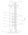
- Fig. 1a shows a former arrangement, in the two paper webs 01, 02 next to each other via a roller 03 and then in two formers 06, 07 are performed.
- the formers 06, 07 are in a frame 04 parallel to the axis of the roller 03rd slidably mounted.
- An actuator for moving the former 06, 07 is formed by a parallel to the axis of the roller 03 threaded spindle 08, the two sections with having opposite slope, and a drive 11, z. B. electric motor 11, for rotational driving the threaded spindle 08.
- the drive 11 and the former 06; 07 moving gear can also be carried out in other ways.
- the formers 06, 07 are each provided with a sliding block 09, wherein the two sliding blocks 09 with different sections of the threaded spindle 08 are engaged, so that a rotation the threaded spindle 08, the former 06, 07 drives to opposite movements.
- An electronic control unit 10 or a system S mentioned below Presetting controls the electric motor 11 based on a user at the Control unit 10 entered (or the system S present) width of the Paper webs 01, 02.
- the information about the width of the control device 10 in other ways, for. B. by reading a common value or one in a product planning system, a machine control, a Imposition scheme and / or a control station (denoted by P in FIG. 9) stored value.
- a connected to the left former 06 frame 15 or frame 15 is used at the same time as a support for a bearing of the roller 03, so that the roller 03 every movement the Former 06 follows.
- the right side of the roller 03 is on a frame 04 fixed pin telescopic, z. B. via an axially displaceable bearing 25 (Fig. 1 b), displaceable.
- Fig. 1 b axially displaceable bearing 25
- displaceable With the folding hopper 06, thus displacing the roller 03 and z. B. one on the roller 03 circumferential groove 20 (dashed line in Figure 1 b), which with a Knife for continuous or discontinuous longitudinal cutting as a cutting groove works together.
- Intervallschneidmesser 05 Also rigid with the former 06, z. B. on the frame 15, is connected Intervallschneidmesser 05 or Skip Slitter 05, which is mounted above the roller 03.
- the Intervallschneidmesser 05 has a rotating interrupted blade, with the Folding line of the former 06 aligned and alternately on the paper web 01 printed pairs of printed pages each alternately intersects a pair and that others left uncut.
- the uncut side pairs are around Broadsheet pages with transverse to the conveying direction lines and the sliced around tabloid sides whose rows are oriented in the conveying direction, so can be from the paper web 01 in a connected, not shown Folder in a simple way a signature with a deposit in half the page size produce.
- Fig. 1 b is the setting of the former 06, 07 for the processing of two Paper webs 12, 13 shown opposite to the paper webs 01, 02 of FIG. 1 a are narrower by a value d.
- the center line M at which the tracks 12, 13 touch, has the same position with respect to the frame as the center line M between the Webs 01, 02 in Fig. 1a.
- the threaded spindle 08 rotated, so that the former 06, 07 each shifted by d / 2 to the center line M out become.
- the former 06; 07 in addition to or instead of the connection to the knife 05 - one of the funnel tip downstream driven roller 30 together or simultaneously with the Forming hopper 06; 07 laterally movable.
- the former 06; 07 preferably over a common frame 15 connected to a bearing of the roller 30. at Moving the former 6, 07, the roller 30 is moved simultaneously.
- the roller 30 is designed either as a driven transfer roller 30, via which a the former 06; 07 leaving strand is guided and undergoes a change in direction.
- the roller 30 as z. B. single motor driven tension roller 30 a Ceizenen be executed, against which a pressure roller 35 is adjustable. In In this case, the entire train group 30, 35 with the former 06; 07 connected.
- the controller 10 and the drive 11 for the described movement the former funnel 06; 07 is in signal communication with the system S.
- Production data eg the web or partial web width b; b '
- a predetermined or predefinable for this production situation compared and, if necessary, a corresponding movement via setting commands to the relevant Drive 11 causes.
- the Forming hopper 06; 07 is z. B.
- Preset values can be tabulated for the various productions, or it can be found in the System a calculation based on the by the web widths and the lateral offset resulting railways instead.
- Fig. 2a shows a catching roller arrangement as a further example of Web processing tools of a device according to the invention.
- These Fang roller assembly consists of a roller 14, which in operation of a catching, is wrapped in the figure, not shown paper web, a plurality of rollers 16, a plurality of sliding blocks 18, 19, 21, a guide rail 17, a threaded spindle 22nd and one of the already mentioned control unit 10 (or system S) controlled Electric motor 23.
- the roller 14 is rotatably mounted in the frame 04. Parallel to the roller 14 is the Guide rail 17 mounted in the frame 04. On the guide rail 17 are several Sliders 18, 19 arranged displaceably. A central to the roller 14 arranged Slider 21 is fixedly arranged on the guide rail 17.
- the sliding blocks 18, 19 and 21 each carry a rotatably mounted roller 16. The rollers 16 press against the Roller 14 and roll against this. Since the rollers 16 only rotate in one direction are designed to prevent them from running back around the roller 14 Paper web in case of a paper web break.
- the threaded spindle 22 pierces the frame 04 on one side and protrudes at this point out of frame 04 It is parallel to the roller 14 and the guide rail 17 aligned.
- the threaded spindle 22 has two different Thread sections with different directions of rotation, which by a threadless Section are separated. On this threadless section is the sliding block 21 arranged.
- the two threaded sections have slopes that run along one Longitudinal axis of the threaded spindle 22 proportional to the distance from the sliding block 21st increase.
- the sliding blocks 18, 19 are left with the seen from the sliding block 21 from or right threaded section not about an internal thread with several Windings engaged - such would be due to the variability of the slope stuck stay, but over a single narrow pin, which on a small Peripheral portion of the threaded spindle 22 engages in the thread on the off the frame 04 protruding end portion of the threaded spindle 22 engages the Electric motor 23 to the threaded spindle 22 at.
- the sliding blocks 18, 19 along the guide rail 17th shifted, as shown in Fig. 2b.
- the threaded spindle 22 via the drive 23rd turned. Due to the different sense of rotation of the two with the sliding blocks 18 and 19 engaged threaded portions move at a rotation of the Threaded spindle 22, the sliding blocks 18 from the left and the sliding blocks 19 from the right on the central sliding block 21 too.
- the movement of the sliding blocks 18, 19 takes place synchronously, however, as a result of changing along the longitudinal axis of the threaded spindle 22 Slopes of the threaded portions are the paths that the sliding blocks 18, 19 and thus the rollers they drive are 16, proportional to their distance from middle sliding block 21.
- the Sliders 18, 19 via a corresponding rotation of the threaded spindle 22 more or less close to the sliding block 21 steplessly move, and the Fangrolle so that set any paper web widths.
- the sliding blocks 18, 19 can before a Displacement can be arbitrarily placed on the spindle 22; the ratio of their distances remains with a shift.
- threaded spindles each with two sections of opposite be provided with the same pitch, the respective sliding blocks of each other with respect to the Bear center line M mirrored opposite roles.
- These threaded spindles are expediently identical to each other.
- the threaded spindles of a common electric motor via a gearbox with each adapted Gear ratio driven, or each threaded spindle has its own Electric motor provided by the control unit individually according to the required Shift is controlled.
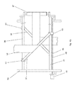
- FIG. 3a shows a longitudinal cutting device 71 of a superstructure 67 (FIG. 9).
- the Longitudinal cutting device 71 is adapted to an incoming web in a plurality Partial webs, e.g. cut longitudinally two partial webs.
- a paper web 26 is passed between the two guide rails 24.
- Two carriages 27 are on the two guide rails 24 slidably held. They are mirror images of each other executed and mounted.
- Each carriage 27 carries a rotating knife 28 with vertical to the paper web 26 aligned cutting edge and one with the knife 28th cooperating counter-pressure roller 29 (counter knife).
- a parallel to the guide rails 24 threaded spindle 33 has two Thread sections with different directions of rotation and the same pitch, of which each engaged with one of the carriages 27.
- An end portion of the threaded spindle 33 protrudes from the frame 04 on one side.
- a drive 34, z. B. electric motor 34, for rotational driving of the threaded spindle 33 is provided.
- the single knife 28; 32 or counter knife can also be together by a different type of drive 34 or by individual drives per knife or knife pair be drivable.
- the threaded spindle 33rd rotated by the electric motor 34. Since the carriage 27 on different Threaded portions of the threaded spindle 33 with different rotation and the same Slope engaged, causes the rotation of the threaded spindle 33 that the Carriage 27 to each other equal distances to each other or to the central blade 32 to move. The rotation of the threaded spindle 33 is continued until the Distance between two knives 28, 32 one quarter of the width of the narrow paper web 36 corresponds.
- the operation of the motor 34 is controlled by the control unit 10 (or system S) ( Figure 1a). controlled or predetermined, the positions of the knife 28 based on a user widths set or automatically detected by sensors (not shown) cutting web or the partial webs resulting from the cutting.
- knife units may e.g. all individually driven and / or individually on / off.
- the axial positioning or at least presetting of the machine control is preferably automatically based on the intended for printing width of Track and the product-specific cut lines or from a control panel made manually. This is done, for example, before the production start of the system S (from the machine control or a corresponding software program) the current setting to the preset values required for the planned production checked and / or a default by acting on the drive 34 (or the Drives 34). Such default values can be tabulated for the be deposited in different productions, or it can be found in the system S one Calculation using the through the web widths and the to be obtained lateral offset instead.
- Fig. 4a is a turning table with two crossed turning bars 37, 38 as another Example of web processing tools shown to be present in the device can.
- Two pairs of guide rails 39, 41 as the front 41 and rear Guide rails 39, are held between plates of the frame 04. From Each pair of guide rails 39, 41 is only an upper guide rail in the figure too see as it covers the underlying to her underlying rail.
- a sliding block 42, 43 is provided, wherein the sliding block 42 on the visible upper guide rail 39 of the rear guide rail pair and the sliding block 43 on the visible upper guide rail 41 of the front Guide rail pair is slidably disposed.
- a deflection roller 47 rotatably arranged.
- a perpendicular to the guide rail pairs 39 and 41 incoming paper web 51st rotates the inclined turning bar 37 and thereby changes their direction of rotation by 90 °. she wraps around the guide roller 47 and runs from this back and over the oblique Asked, with the turning bar 37 crossed turning bar 38, which is their Changing direction again by 90 °, so that after leaving the turning table their original running direction has returned, but by exactly one paper web width is offset and turned.
- each spindle 48 engages a drive 49, e.g. an electric motor 49 on.
- the control unit 10 controls a opposite movement of the motors 49 and thus the turning bars 37, 38th Zum others, especially if more than two partial webs are to be processed, one same direction displacement of the turning bars 37, 38 may be required to ensure that the partial webs are not too close to the ends of the turning bars 37, 38 come.
- the control unit 10 controls the motors 49, respectively in the same direction.
- the reversing deck just described is shown in Fig. 5a after a conversion.
- the Turning bars 37 and 38 are parallel to each other in this embodiment Slide blocks 42, 43, 44, 46 on the guide rails of the pairs of guide rails 39 and 41 slidably arranged.
- a paper web 53 to be offset runs perpendicular to the guide rail pairs 39 and 41 in the turning corner, wraps successively the turning bar 37 and the Turning bar 38, and leaves the turning table laterally offset by a paper web width, without being turned.
- Fig. 6 shows an advantageous embodiment of the turning bar arrangement according to Fig. 4, wherein the arrangement, however, only one support 39; 41 for the two turning bars 37, 38.
- the sliding blocks 43; 46 slide on the same support 39; 41 and become driven by a common threaded spindle 48, which two opposing Has thread for each one of the sliding blocks.
- the spindle is driven by the motor 49 driven, wherein upon rotation of the threaded spindle, the sliding blocks 43; 46 move in opposite directions.
- Fig. 7 also shows an advantageous embodiment of the arrangement according to Fig. 5, wherein here as in Fig. 6, a common threaded spindle 48 with opposite threads for the Sliding blocks 43; 46 is provided.
- the sliding blocks 43; 46 are also running on the same Carrier 41.
- Driving the threaded spindle 48 through the common motor 49th causes an opposite movement of the two turning bars 37; 38 with her Sliding blocks 43; 46th
- a turning tool 72 of a printing machine has at least one turning table two mutually associated turning bars 37; 38, by means of which a partial web 51 until 54 can be brought to another flight and / or overthrown. It includes one Pair of turning bars 37; 38. In an advantageous embodiment, not shown here are two turning corners, i. two pairs of turning bars 37; 38 to the offset or to Falls of two partial webs 51 to 54 provided.
- the turning bars 37; 38 of a couple can be as shown either parallel to each other and 45 ° to the incoming Track can be arranged inclined (offset), or they are perpendicular to each other arranged and inclined at 45 ° or 135 ° to the incoming web (falls and possibly Offset).
- all turning bars 37; 38 in the level of each incoming web by 90 ° swivel or tilted executed.
- the carrier accounts for 39.
- the turning bars 37; 38 each an unillustrated means associated with which the current position of the turning bar 37; 38 - to the left or to Tilted to the right - recorded and sent to the machine control or the control console of the machine or the system S reports.
- These may be, for example, initiators, which mechanical (switch) or electromagnetic (induction, photocell) activated or be deactivated as soon as the turning bar 37; 38 in one of the intended locations located.
- the printer or a program can then check if the Turning bars 37; 38 in the position required for the planned production. It can be output by the system S an error signal when the position of the Turning bar 37; 38 to the intended production (or web run) does not match.
- Each turning bar 37; 38 is as shown above in a preferred embodiment in total arranged in a direction transverse to the incoming path movable in the superstructure 67.
- the turning bar 37; 38 adapted to a product or a web run or Web width can be positioned by means of the drive 49.
- the Drives 49 of the turning bars 37; 38 are in signal communication with the system S. Based on the production data (eg planned web guide, resulting theoretical cutting line, and / or web or partial web width), the current position of Turning bar 37; 38 with a predefined or predetermined for this production situation compared and, if necessary, a corresponding movement via setting commands to the relevant Drives 49 causes.
- Such default values can be tabulated for the be deposited in different productions, or it can be found in the system S one Calculation using the through the web widths and the to be obtained lateral offset instead.
- the pivotable turning bars 37; 38 associated with an unillustrated drive for panning, which, for example, like set forth for the drives 49, by the o. g. System S according to the planned Production and / or web guide is preset.
- a drive is advantageous For example, designed as a pressurizable cylinder, which on a Side with the frame and on the other with the turning bar 37; 38 outside of her Fulcrum attacks.
- Fig. 8 shows a schematic side view of the former as 06; 07 executed Web processing tool.
- the former 06; 07 is in an advantageous embodiment in a direction (at least one component) movable perpendicular to the Back fold of the former 06; 07 leaving strand and / or substantially parallel to a rotation axis of a cylinder (cross-cutting cylinder, Folding blade cylinder and / or jaw cylinder) of a downstream folder 68 (see Fig. 9).
- This allows the correct entry into the cylinders of the folder Adjust 68 for different web or strand widths and / or layers.
- an unillustrated drive for the described movement of the former 06; 07 in Signal connection with a controller 10 or advantageously with the system S is.
- Based the production data eg the rail or partial web width
- the production data is the current position of the Forming former 06; 07 with a predetermined or predefinable for this production situation compared and, if necessary, a corresponding movement via setting commands to the relevant Drive causes.
- a corresponding movement via setting commands to the relevant Drive causes.
- sectionbahn- or strand width of the former 06; 07 (or the funnel tip) to position accordingly.
- the former 06; 07 is z. B. Positioned such that the folded strand for each width in a suitable manner -.
- Preset values can be tabulated for the various productions, or it can be found in the System a calculation based on the by the web widths and the lateral offset resulting railways instead.
- the aforementioned web processing tools are single or multiple Part of a web-processing and / or processing machine, z. B. printing press (Fig. 9), in particular a web-fed rotary printing press for printing on or several tracks B.
- a web-fed rotary printing press for printing on or several tracks B.
- This has z. B. several units 61; 62; 63; 64; 65; 66; 67; 68; 69 for supply, for printing and for further processing.
- one Roll handling 61 becomes the web B to be covered, in particular paper web B, unwound before passing over a feeder 62 of one or more printing units 63 is supplied.
- Printing units 63 may include additional printing units Be provided 63, which then, for example, also alternately to one or several of the remaining printing units 63 can be used for the flying printing form change are.
- the printing units 63 can also be z.T. vertically above each other Bridge printing units 63 or as (nine- or ten-cylinder) satellite printing units be executed.
- a coating unit 64 may be provided in the web path.
- the web B passes through, for example, one Dryer 65 and is optionally cooled in a cooling unit 66 again, if the drying carried out in a thermal manner.
- a drying unit 66 at least one further, not shown in Fig. 9 conditioning device, such as. a coating device and / or a Wiederbefeuchtung be provided.
- the web B via a superstructure 67 a Folder 68 are supplied.
- the superstructure 67 has z. B. not in Fig. 1 illustrated silicone work, the longitudinal cutting device 71 and a at least one Reversing device having turning device 72 or Wendewerk 72 and a the or the formers 06; 07 having funnel unit 73.
- the said silicone work can also in front of the superstructure 67, e.g. be arranged in the region of the cooling unit 66.
- the Mathbaubau 67 can continue a not shown in Fig. 9 perforating, a gluing plant, have a numbering and / or a Pflugfalz. After passing through the superstructure 67 becomes the web B or partial webs B1; B2 guided in the folder 68.
- the printing press additionally has a separate one Sheeter 69, e.g. a so-called. Plano boom 69, on, in which an example not guided by the folding apparatus 68 web B cut in size sheet and possibly stacked or laid out.
- a separate one Sheeter 69 e.g. a so-called. Plano boom 69, on, in which an example not guided by the folding apparatus 68 web B cut in size sheet and possibly stacked or laid out.
- the machine is preferably the system S for default, z. B. as additional Program assigned in a machine control and / or a planning system, which in logical signal connection to one or more of the o. g. Machining tools or aggregates 61; 62; 63; 64; 65; 66; 67; 68; 69, in particular the aggregates 61; 63; 67 stands.
- web processing tools are in o.g. Context thus further Meaning also to understand sensors and actuators, which have an influence on the recording and exercise the influence of the run of a train or sub-train or strand.
- presetting the press When presetting the press now receives z. B. before the start of a production System S from a product planning system, a pre-press stage, the Printer itself and / or an existing imposition scheme for presetting relevant data for planned production.
- the imposition includes z. B. for the planned production scheduled rail or partial railway lines and the occupancy of Form cylinder with the printed pages and the colors of the individual printing units.
- information to the web width and / or the intended lateral position of the web can by the Printer be entered or by a machine control, the Reel changer 71 itself, a logistics system or a product planning system be obtained.
- the Turning bars 37; 38 and possibly one of the sub-railway in the superstructure 67 assigned Longitudinal register means 58 are z. B. the information on the intended train or Partial railways processed. In further training, a presetting of colorimeters in the printing units z. B. using data from the print preparation and / or the imposition scheme (color densities, occupancy, etc.).
- the longitudinal cutter 71 with respect to pre-set to be processed web.
- the roll changer 61 may be without this "outer" preset by its own internal control loop always centered be.
- the former 06; 07 and the funnel unit 73 positioned (laterally and / or in the direction of paper travel).
- a second variant of the printing machine is at least by the system S or the controller 10 the positioning (side and / or in the direction of paper travel) of the Forming former 06; 07 or the former 06; 07 preset. With the former 06, 07 together then a knife 05 and / or a downstream driven roller 30th be positioned and connected to it.
- the roll changer 61 can in this case if necessary, again without "outer" presetting by its own inner control loop always be settled on middle.
- the default setting of the system S for Slitter 71 i.e., at least one knife 28, 32
- the Turning 72 and possibly additionally made for the reel changer 61.
- the former 06; 07 positioned.
- Expansion stages can advantageously be a default of Color meter and / or the stripping done by the system S.
- one of o. G. various selection of pre-set units or sub-units be provided.
- a default setting can only be applied to the Adjustment of the ink knife and the longitudinal cutter 71 judge while in other design all intended for web guiding and cutting Aggregates or sub-assemblies, in particular those of the superstructure 67 to Presetting are provided.
- Extension stages and their variants can advantageously be a Presetting of cut register and / or Farbregistermessgliedern 56, z. Heads, and / or a web edge control 57 in the axial direction with respect to the new Production are made, and / or an adjustment of the pressure roller 35 (z. Rollers) on the draw roller 30 with respect to an expected strand thickness below the former funnel 06; 07 takes place.
- the drives 11; 23, 34, 49 of the said processing tools, at least for Presetting provided editing tools are preferably remotely operable executed or remotely operated by the system S or the controller 10. In contrast to manually or only locally actuated actuators is thereby the Presetting in one or more of the aforementioned embodiments and variants comfortable and fast via the system S and / or the control station possible.
- the system S can be designed as a control unit S, which is a User interface for inputting and / or an interface for reading in (from the Machine control, a production planning system and / or a Druckvorkungseck) at least one width and / or a Bruweges one processing path, calculating means for determining a desired position of Pre-set units, sub-units or machining tools such as Roll changer 61, the slitter 71, the turning bar 37; 38, one of the Part web associated longitudinal register means 58 and / or the former 06; 07 based on the web width and / or the web path and driver for driving the associated actuators to set the respectively determined target position includes.
Landscapes
- Folding Of Thin Sheet-Like Materials, Special Discharging Devices, And Others (AREA)
- Replacement Of Web Rolls (AREA)
- Nonmetal Cutting Devices (AREA)
- Rotary Presses (AREA)
- Preliminary Treatment Of Fibers (AREA)
- Electroplating Methods And Accessories (AREA)
- Heat Treatment Of Strip Materials And Filament Materials (AREA)
- Control Of Heat Treatment Processes (AREA)
- Cleaning Implements For Floors, Carpets, Furniture, Walls, And The Like (AREA)
- Electrical Discharge Machining, Electrochemical Machining, And Combined Machining (AREA)
- Machines For Laying And Maintaining Railways (AREA)
Abstract
Description
Die Erfindung betrifft eine Vorrichtung zur Bearbeitung und/oder Förderung einer Bahn gemäß dem Oberbegriff des Anspruchs 1.The invention relates to a device for processing and / or conveying a web according to the preamble of claim 1.
Aus der EP 12 38 935 A2 ist eine Vorrichtung zum Längsschneiden von Folien und
Bändern bekannt, wobei ein Obermesser zur Einstellung einer Schnittbreite quer zur
Transportrichtung der Bahn positionierbar ist.From
Durch die DE 101 50 810 A1 ist ein Rollenwechsler bekannt, wobei zwei Rollenarme zur Aufnahme einer Rolle ein Paar bilden und jeweils einzeln durch einen eigenen Motor entlang einer Rotationsachse der Rolle bewegbar sind.By DE 101 50 810 A1 a reel changer is known, wherein two roller arms for Take a role form a pair and each individually by its own engine along a rotation axis of the roller are movable.
Die DE 196 02 248 A1 offenbart einen Falztrichter, welcher zur seitlichen Korrektur des gefalzten Stranges entlang eines Einlaufspaltes zweier nachgeordneter Walzen bewegbar ist.DE 196 02 248 A1 discloses a former, which for lateral correction of folded strand along an inlet gap of two subordinate rolls movable is.
Durch die WO 01/70608 A1 ist eine quer zur Einlaufrichtung der Bahn positionierbare
Wendestange und eine längs zur Einlauflichtung des Bahn positionierbare Registerwalze
bekannt. Die Wendestange ist in der Weise verschwenkbar, dass sie je nach Stellung die
Bahn nach rechts oder links umlenkt.By
Die DE 36 14 981 C2 offenbart zwei Bahnkantenfühler, welche jeweils über einen Antrieb verfügen und über eine gemeinsame Steuereinrichtung angesteuert werden. Ähnliches offenbart die DE 35 33 274 C3.DE 36 14 981 C2 discloses two web edge sensors, each having a drive have and be controlled by a common control device. something similar discloses DE 35 33 274 C3.
In der DE 195 40 164 C1 ist eine Transportrichtung mit zwei nebeneinander angeordneten Fördereinrichtungen für Endlosmaterial gezeigt, wobei jede Einrichtung eine axial bewegbare Vorschubeinrichtung aufweist.In DE 195 40 164 C1, a transport direction with two arranged side by side Conveyors for endless material shown, each device an axial having movable feed device.
Eine Vorrichtung, mit der es möglich ist, aus einer laufenden Papierbahn maximaler Breite
zwei Teilbahnen oder drei Teilbahnen von variabler Breite zu schneiden und diese
Teilbahnen zu falzen, ist aus der DE 42 04 254 A1 bekannt. Die dort gezeigte Vorrichtung
umfasst drei Falztrichter, die in zwei Ebenen angeordnet sind, wobei zwei in einer ersten
Ebene benachbarte Falztrichter quer zur Laufrichtung der Papierbahn verfahrbar
angeordnet sind, um wahlweise zum Falzen beider Teilbahnen einer zweigeteilten
Papierbahn oder zum Falzen der zwei äußeren Teilbahnen einer dreigeteilten Bahn zu
dienen. Eine Anpassung anderer bahnführender Einrichtungen als der Falztrichter an die
jeweilige Bahnbreite ist nicht vorgesehen.A device with which it is possible, from a running paper web of maximum width
to cut two partial webs or three partial webs of variable width and these
To fold partial webs, is known from
Aus der DE 43 11 437 A1 ist eine Wendestangenanordnung bekannt, deren
Wendestangen umlegbar sind, um eine an ihnen gewendete Bahn um ihre Breite je nach
Stellung der Wendestangen nach links oder nach rechts zu versetzen. Diese
Wendestangenanordnung ist mit der Vorrichtung aus DE 42 04 254 A1 nicht ohne
weiteres kombinierbar, da eine mit ihr z.B. um eine halbe Bahnbreite versetzte drittelbreite
Teilbahn nicht den für sie bestimmten Falztrichter trifft.From
Die DE 100 03 025 C1 offenbart eine Vorrichtung zur Bearbeitung einer Bahn mit mindestens einem Falztrichter und einem diesem vorgeordneten als Messer, wobei das Messer und der Falztrichter durch ein gemeinsames Stellglied quer zur Laufrichtung der Bahn bewegbar sind.DE 100 03 025 C1 discloses a device for processing a web with at least one former and this upstream as a knife, wherein the Knife and the former through a common actuator transverse to the direction of the Railway are movable.
In der US-A-3 734 487 sind als Wendestangen, als Längsschneidmesser und als
Registerwalze ausgeführte Bahnbearbeitungs- bzw. -leitelemente offenbart, welche durch
einzelne Antriebe im Hinblick auf geplante Produktionen vorpositionierbar sind.
Die EP 0 457 304 A1 betrifft einen Mechanismus mit zwei gegensinnig durch einen
gemeinsamen Antrieb bewegbare Bearbeitungselemente einer Vorrichtung zur Falzung
von Taschen.US-A-3 734 487 discloses web-processing or guiding elements embodied as turning bars, as longitudinal cutting knives and as a register roll, which can be prepositioned by individual drives with regard to planned productions.
EP 0 457 304 A1 relates to a mechanism with two processing elements of a device for folding bags that can be moved in opposite directions by a common drive.
Der Erfindung liegt die Aufgabe zugrunde, eine Vorrichtung zur Bearbeitung und/oder Förderung einer Bahn zu schaffen.The invention is based on the object, a device for processing and / or To promote a railway.
Diese Aufgabe wird erfindungsgemäß durch die Merkmale des Anspruchs 1 gelöst.This object is achieved by the features of claim 1.
Ein wesentlicher mit der Vorrichtung bzw. dem Verfahren erzielbarer Vorteil liegt einerseits darin, dass ein langwieriges Einstellen bei Produktionsbeginn entfällt. Im Gegensatz zu Einstellungen, welche erst während der Druckaufnahme mittels Regelkreisen erfolgt, ist die Menge an Makulatur deutlich verringerbar.An essential advantage achievable with the device or the method lies in this on the one hand that a lengthy adjustment at the beginning of production is eliminated. in the Contrary to attitudes, which only during the pressure admission means Control loop occurs, the amount of waste is significantly reduced.
Ein besonderer Vorteil der Erfindung ist, dass sie eine schnelle Anpassung an eine Veränderung der zu verarbeitenden Bahnbreiten ermöglicht, da ein Benutzer nicht auf jedes einzelne in Anpassung an die Bahnbreite zu verschiebende Bahnbearbeitungswerkzeug einzeln zugreifen muss.A particular advantage of the invention is that it allows rapid adaptation to a Changing the web widths to be processed, as a user does not open each to be moved in adaptation to the web width Web editing tool must access individually.
Eine weitere Zeitersparnis ergibt sich, wenn die Steuereinheit selbst eingerichtet ist, die notwendigerweise miteinander korrelierten Positionen der verschiedenen Bearbeitungswerkzeuge aus einer geringen Zahl von Eingabeparametern selbsttätig zu berechnen und einzustellen. Im einfachsten Falle genügt es zur Berechnung dieser Positionen, lediglich die Breite einer zu verarbeitenden Bahn vorzugeben; die Steuereinheit kann aus dieser Vorgabe die erforderlichen Positionen aller Bearbeitungswerkzeuge auf einfache Weise unter der Voraussetzung ermitteln, dass eine Referenzlinie aller zu verarbeitenden Bahnen, z. B. ein rechter oder linker Rand oder vorzugsweise die Mittellinie, unabhängig von deren Breite in der Vorrichtung die gleiche Position einnimmt. Another time saving results when the control unit itself is set up necessarily correlated positions of the different Automatic editing tools from a small number of input parameters calculate and adjust. In the simplest case, it is sufficient to calculate this Positions to specify only the width of a web to be processed; the Control unit can from this specification the required positions of all Determine editing tools in a simple way on condition that a Reference line of all webs to be processed, z. B. a right or left margin or preferably the center line, regardless of their width in the device the same Takes position.
Da die zur Anpassung an eine geänderte Bahnbreite erforderlichen Verschiebungen mancher Bahnbearbeitungswerkzeuge fest korreliert sind, lässt sich die Vorrichtung vereinfachen, indem ein Stellglied zum Verschieben mehrerer Bahnbearbeitungswerkzeuge gleichzeitig eingesetzt wird.Because the required to adapt to a changed web width shifts some web editing tools are firmly correlated, the device can be Simplify by using an actuator to move multiple Web processing tools is used simultaneously.
Zu den Bahnbearbeitungswerkzeugen der erfindungsgemäßen Vorrichtung gehört beispielsweise wenigstens ein Falztrichter. Bei geeigneter Wahl der Referenzlinie kann es genügen, wenn nur einer von zwei Falztrichtern verschiebbar ist; wählt man jedoch, was bevorzugt ist, die Mittellinie der zu verarbeitenden Bahn als Referenzlinie, so müssen wenigstens beide von zwei nebeneinander angeordneten Falztrichter verschiebbar sein.Belongs to the web processing tools of the device according to the invention for example, at least one former. With a suitable choice of the reference line it can are sufficient if only one of two formers is displaceable; However, you choose what is preferred, the center line of the web to be processed as a reference line, so must at least both of two juxtaposed folders to be displaced.
Um aus einer einzelnen Ausgangsbahn in der erfindungsgemäßen Vorrichtung mehrere Teilbahnen zu erzeugen, die dann jeweils einzelnen Falztrichtern zugeführt werden können, weist die erfindungsgemäße Vorrichtung zweckmäßigerweise wenigstens ein Messer zum Längsschneiden der Ausgangsbahn in Teilbahnen auf. Wenn mehr als ein solches Messer vorhanden ist, muss wenigstens eines von ihnen verschiebbar sein.To from a single output track in the inventive device several To produce partial webs, which are then fed to each individual formers can, the device according to the invention expediently at least one Knife for longitudinal cutting of the original web in partial webs. If more than one such knife is present, at least one of them must be displaceable.
Die Vorrichtung kann ferner wenigstens ein Intervallschneidmesser zum seitenweisen Längsschneiden der Materialbahn aufweisen. Wenn es sich bei der Materialbahn um eine bedruckte Papierbahn, insbesondere einer Zeitung handelt, kann ein solches Intervallschneidmesser eingesetzt werden, um die Bahn jeweils lokal in Höhe jeder zweiten Seite zu schneiden, um so z. B. eine Broadsheet-Signatur mit Tabloid-Einlage zu produzieren.The device may further comprise at least one interval cutting knife for page-wise Having slitting the web. If the material web is a printed paper web, in particular a newspaper, may be such Intermittent cutting knives are used to lift the web locally at the height of each second side to cut so z. B. a broadsheet signature with tabloid insert too to produce.
Auch ist es von Vorteil, wenn die Vorrichtung eine Längsschneideinrichtung mit mindestens einem Messer aufweist, welches ebenfalls quer zur Laufrichtung der Bahn voreingestellt wird, um die Schnittlinie für die zu erzeugenden Teilbahnen festzulegen.It is also advantageous if the device has a longitudinal cutting device has at least one knife, which also transverse to the direction of the web is preset to set the cutting line for the partial webs to be produced.
Wenn in der Vorrichtung eine in mehrere Teilbahnen zerschnittene Ausgangsbahn verarbeitet wird, so sind Zug- oder Fangrollen als Bahnbearbeitungswerkzeuge zweckmäßigerweise jeder der Teilbahnen in gleicher Weise zugeordnet. Es ist daher wünschenswert, dass solche Rollen ebenfalls entsprechend der Breite der zu verarbeitenden Ausgangsbahn und der Zahl der Teilbahnen automatisch durch die Steuereinheit positionierbar sind.If in the device a cut into several partial webs original web is processed, so are train or Fangrollen as web processing tools expediently assigned to each of the sub-webs in the same way. It is therefore desirable that such roles also according to the width of the processing output track and the number of sub-tracks automatically by the Control unit can be positioned.
Auch Wendestangen können als durch die Steuereinheit verschiebbare Bearbeitungswerkzeuge vorgesehen werden. Als Bearbeitungswerkzeuge werden hier und im folgenden auch Bahnleit-, Bahnantriebs- und/oder Bahnführungselemente, wie z. B. Wendestangen, Andrückrollen und/oder Führungswalzen verstanden.Turning bars can also be displaced by the control unit Processing tools are provided. As editing tools are here and in the following also Bahnleit-, Bahnantriebs- and / or web guide elements, such as z. As turner bars, pressure rollers and / or guide rollers understood.
Zum Antreiben der Verschiebung der Bearbeitungswerkzeuge weisen die Stellglieder vorzugsweise jeweils eine Gewindespindel auf, und die verschiebbaren Bearbeitungswerkzeug haben jeweils einen Gleitstein, der mit einer solchen Gewindespindel im Eingriff ist.To drive the displacement of the processing tools, the actuators preferably in each case a threaded spindle, and the displaceable Machining tool each have a sliding block, with such a Threaded spindle is engaged.
Vorteilhafterweise kann eine solche Gewindespindel mehrere Abschnitte aufweisen, die sich in Drehsinn und/oder Steigung unterscheiden, und die Gleitsteine mehrerer Bearbeitungswerkzeuge gleichen Typs sind jeweils im Eingriff mit den verschiedenen Abschnitten einer gleichen Spindel, um die Bearbeitungswerkzeuge gekoppelt, aber ggf. in unterschiedlichen Richtungen und/oder Geschwindigkeiten zu verschieben.Advantageously, such a threaded spindle can have a plurality of sections which differ in sense of rotation and / or pitch, and the sliding blocks of several Machining tools of the same type are each in engagement with the various Sections of a same spindle coupled to the editing tools, but if necessary to move in different directions and / or speeds.
Ausführungsbeispiele der Erfindung sind in den Zeichnungen dargestellt und werden im Folgenden näher beschrieben.Embodiments of the invention are illustrated in the drawings and are in Described in more detail below.
Es zeigen:
- Fig. 1a
- verschiebbare Falztrichter, eingestellt für eine breite Papierbahn;
- Fig. 1b
- verschiebbare Falztrichter, eingestellt für eine schmale Papierbahn;
- Fig. 2a
- eine Fangrolle mit verschiebbaren Rollen, eingestellt für eine breite Papierbahn;
- Fig. 2b
- eine Fangrolle mit verschiebbaren Rollen, eingestellt für eine schmale Papierbahn;
- Fig. 3a
- eine Längsschneidevorrichtung mit verschiebbaren Messern, eingestellt für eine breite Papierbahn;
- Fig. 3b
- eine Längsschneidevorrichtung mit verschiebbaren Messern, eingestellt für eine schmale Papierbahn;
- Fig. 4a
- verschiebbare gekreuzte Wendestangen, eingestellt für eine breite Papierbahn;
- Fig. 4b
- verschiebbare gekreuzte Wendestangen, eingestellt für eine schmale Papierbahn;
- Fig. 5a
- verschiebbare parallele Wendestangen, eingestellt für eine breite Papierbahn;
- Fig. 5b
- verschiebbare parallele Wendestangen, eingestellt für eine schmale Papierbahn;
- Fig. 6
- verschiebbare gekreuzte Wendestangen mit einer gemeinsamen Antriebsvorrichtung;
- Fig. 7
- verschiebbare parallele Wendestangen mit einer gemeinsamen Antriebsvorrichtung;
- Fig. 8
- in Bahnlaufrichtung bewegbarer Falztrichter;
- Fig. 9
- eine schematische Darstellung einer Druckmaschine.
- Fig. 1a
- sliding formers, adjusted for a wide paper web;
- Fig. 1b
- sliding formers, adjusted for a narrow paper web;
- Fig. 2a
- a caster roll with slidable rolls set for a wide paper web;
- Fig. 2b
- a caster roll with slidable rolls set for a narrow paper web;
- Fig. 3a
- a slitter with slidable knives set for a wide paper web;
- Fig. 3b
- a slitter with slidable knives set for a narrow paper web;
- Fig. 4a
- sliding crossed turning bars set for a wide paper web;
- Fig. 4b
- sliding crossed turner bars set for a narrow paper web;
- Fig. 5a
- sliding parallel turning bars set for a wide paper web;
- Fig. 5b
- sliding parallel turning bars set for a narrow paper web;
- Fig. 6
- sliding crossed turning bars with a common drive device;
- Fig. 7
- sliding parallel turning bars with a common drive device;
- Fig. 8
- in the web running direction movable former;
- Fig. 9
- a schematic representation of a printing press.
Fig. 1a zeigt eine Falztrichteranordnung, in der zwei Papierteilbahnen 01, 02
nebeneinander über eine Walze 03 und dann in zwei Falztrichter 06, 07 geführt werden.
Die Falztrichter 06, 07 sind in einem Gestell 04 parallel zur Achse der Walze 03
verschiebbar gelagert. Ein Stellglied zum Verschieben der Falztrichter 06, 07 ist gebildet
durch eine zur Achse der Walze 03 parallele Gewindespindel 08, die zwei Abschnitte mit
entgegengesetzt gleicher Steigung aufweist, und einen Antrieb 11, z. B. Elektromotor 11,
zum Drehantreiben der Gewindespindel 08. Der Antrieb 11 und das den Falztrichter 06;
07 bewegendes Getriebe können auch in anderer Weise ausgeführt sein. Die Falztrichter
06, 07 sind jeweils mit einem Gleitstein 09 versehen, wobei die zwei Gleitsteine 09 mit
verschiedenen Abschnitten der Gewindespindel 08 im Eingriff sind, so dass eine Drehung
der Gewindespindel 08 die Falztrichter 06, 07 zu gegenläufigen Bewegungen antreibt.
Eine elektronische Steuereinheit 10 oder ein unten genanntes System S zur
Voreinstellung steuert den Elektromotor 11 anhand einer vom Benutzer an der
Steuereinheit 10 eingegebenen (bzw. dem System S vorliegenden) Breite der
Papierbahnen 01, 02. Die Information über die Breite kann der Steuereinrichtung 10 (bzw.
System S) auch auf anderer Weise, z. B. durch Einlesen eines gemeinsamen Wertes oder
eines in einem Produktplanungssystem, einer Maschinensteuerung, einem
Ausschießschema und/oder einem Leitstand (in Fig. 9 gleichbedeutend mit P bezeichnet)
vorgehaltenen Wertes implementiert werden.Fig. 1a shows a former arrangement, in the two
Ein mit dem linken Falztrichter 06 verbundener Rahmen 15 oder Gestell 15 dient
gleichzeitig als Träger für ein Lager der Walze 03, so dass die Walze 03 jeder Bewegung
des Falztrichters 06 folgt. Die rechte Seite der Walze 03 ist auf einem am Gestell 04
festen Zapfen teleskopisch, z. B. über ein axial verschiebbares Lager 25 (Fig. 1 b),
verschiebbar. Mit verschieben des Falztrichters 06 verschiebt sich somit die Walze 03 und
z. B. eine auf der Walze 03 umlaufende Nut 20 (strichliert in Fig 1 b), welche mit einem
Messer für den kontinuierlichen oder diskontinuierlichen Längsschnitt als Schneidnut
zusammen wirkt.A connected to the left former 06
Ebenfalls starr mit dem Falztrichter 06, z. B. über das Gestell 15, verbunden ist ein
Intervallschneidmesser 05 oder Skip Slitter 05, das oberhalb der Walze 03 montiert ist.
Das Intervallschneidmesser 05 hat eine rotierende unterbrochene Klinge, die mit der
Falzlinie des Falztrichters 06 fluchtet und von abwechselnd auf die Papierteilbahn 01
gedruckten Paaren von Druckseiten jeweils abwechselnd ein Paar schneidet und das
andere ungeschnitten lässt. Wenn es sich bei den ungeschnittenen Seitenpaaren um
Broadsheet-Seiten mit quer zur Förderrichtung orientierten Zeilen und bei den
geschnittenen um Tabloid-Seiten handelt, deren Zeilen in Förderrichtung orientiert sind,
so lässt sich aus der Papierteilbahn 01 in einem angeschlossenen, nicht dargestellten
Falzapparat auf einfache Weise eine Signatur mit einer Einlage in der halben Seitengröße
herstellen.Also rigid with the former 06, z. B. on the
In Fig. 1 b ist die Einstellung der Falztrichter 06, 07 für die Bearbeitung von zwei
Papierteilbahnen 12, 13 gezeigt, die gegenüber den Papierteilbahnen 01, 02 der Fig. 1 a
um einen Wert d schmaler sind. Die Mittellinie M, an der sich die Bahnen 12, 13 berühren,
hat in Bezug auf das Gestell die gleiche Position wie die Mittellinie M zwischen den
Bahnen 01, 02 in Fig. 1a. Zur Einstellung der Falztrichter 06, 07 für die Bearbeitung solch
schmaler Papierteilbahnen 12, 13 wird über den Elektromotor 11 die Gewindespindel 08
verdreht, so dass die Falztrichter 06, 07 jeweils um d/2 zur Mittellinie M hin verschoben
werden.In Fig. 1 b is the setting of the former 06, 07 for the processing of two
In einer vorteilhaften Abwandlung bzw. Weiterbildung ist mit dem Falztrichter
06; 07 - zusätzlich oder anstelle der Verbindung zum Messer 05 - eine der Trichterspitze
nachgeordnete getriebene Walze 30 zusammen bzw. gleichzeitig mit dem
Falztrichter 06; 07 seitlich bewegbar. Hierzu ist der Falztrichter 06; 07 vorzugsweise über
ein gemeinsames Gestell 15 mit einer Lagerung der Walze 30 verbunden. Bei
Verschieben des Falztrichters 06, 07 wird gleichzeitig die Walze 30 bewegt. Die Walze 30
ist entweder als getriebene Überführwalze 30 ausgeführt, über welche ein den Falztrichter
06; 07 verlassender Strang geführt wird und eine Richtungsänderung erfährt. In anderer
Ausführung kann die Walze 30 als z. B. einzelmotorisch getriebene Zugwalze 30 einer
Zugwalzengruppe ausgeführt sein, gegen welche eine Andrückwalze 35 anstellbar ist. In
diesem Fall ist die gesamte Zuggruppe 30, 35 mit dem Falztrichter 06; 07 verbunden.In an advantageous modification or development is with the former
06; 07 - in addition to or instead of the connection to the knife 05 - one of the funnel tip
downstream driven roller 30 together or simultaneously with the
Forming
Selbstverständlich könnte eine Falztrichteranordnung der in Fig. 1a , 1 b gezeigten Art auch drei oder mehr Falztrichter für die Verarbeitung einer entsprechenden Zahl von Teilbahnen aufweisen. Wenn drei parallele Teilbahnen zu verarbeiten sind und ihre Mittellinie M unabhängig von der Breite der Bahnen stets die gleiche Position in Bezug auf das Gestell hat, so sind die zwei äußeren Falztrichter bei einer Änderung der Breite der Teilbahnen um d jeweils um d zu verschieben, während der mittlere Falztrichter unverschoben bleibt. Bei vier Teilbahnen beträgt entsprechend die Verschiebung d/2 für die zwei mittleren und 3d/2 für die zwei äußeren, etc.Of course, could be a former arrangement of the type shown in Fig. 1a, 1 b also three or more formers for processing a corresponding number of Partial webs have. If three parallel partial webs are to be processed and their Center line M regardless of the width of the webs always the same position in terms of the frame has, so are the two outer formers when changing the width of the To move sub-webs by d each by d, while the middle former remains unshaken. In the case of four partial webs, the displacement d / 2 is correspondingly for the two middle and 3d / 2 for the two outer, etc.
In vorteilhafter Ausführung ist es zur Voreinstellung der Druckmaschine (siehe Fig. 9)
vorgesehen, dass die Steuerung 10 bzw. der Antrieb 11 für die beschriebene Bewegung
des Falztrichters 06; 07 in Signalverbindung mit dem System S steht. Anhand der
Produktionsdaten (z. B. der Bahn- bzw. Teilbahnbreite b; b') wird die aktuelle Lage des
Falztrichters 06; 07 mit einer für diese Produktion vorgegebenen bzw. vorgebbaren Lage
verglichen und ggf. eine entsprechende Bewegung über Stellbefehle an den betreffenden
Antrieb 11 veranlasst. Je nach Bahn- bzw. Teilbahnbreite und/oder Lage deren Mitte ist
der Falztrichter 06; 07 (bzw. die Trichterspitze) entsprechend seitlich zu positionieren. Der
Falztrichter 06; 07 wird z. B. derart Positioniert, dass die Teilbahn 02; 05 mittig bzgl. der
Trichterspitze auf den betreffenden Falztrichter 06; 07 aufläuft. Voreinstellwerte können
tabellarisch für die verschiedenen Produktionen hinterlegt sein, oder aber es findet im
System eine Berechnung anhand der durch die Bahnbreiten und den seitlichen Versatz
resultierenden Bahnwege statt.In an advantageous embodiment, it is for presetting the printing press (see FIG. 9).
provided that the
Fig. 2a zeigt eine Fangrollenanordnung als weiteres Beispiel von
Bahnbearbeitungswerkzeugen einer erfindungsgemäßen Vorrichtung. Diese
Fangrollenanordnung besteht aus einer Walze 14, die im Betrieb von einer zu fangenden,
in der Figur nicht dargestellten Papierbahn umschlungen ist, mehreren Rollen 16,
mehreren Gleitsteinen 18, 19, 21, einer Führungsschiene 17, einer Gewindespindel 22
und einem von der bereits erwähnten Steuereinheit 10 (bzw. System S) gesteuerten
Elektromotor 23.Fig. 2a shows a catching roller arrangement as a further example of
Web processing tools of a device according to the invention. These
Fang roller assembly consists of a
Die Walze 14 ist in dem Gestell 04 drehbar gelagert. Parallel zur Walze 14 ist die
Führungsschiene 17 im Gestell 04 gelagert. Auf der Führungsschiene 17 sind mehrere
Gleitsteine 18, 19 verschiebbar angeordnet. Ein mittig zur Walze 14 angeordneter
Gleitstein 21 ist auf der Führungsschiene 17 fest angeordnet. Die Gleitsteine 18, 19 und
21 tragen jeweils eine drehbar gelagerte Rolle 16. Dabei drücken die Rollen 16 gegen die
Walze 14 und rollen gegen diese ab. Da die Rollen 16 nur in einer Richtung drehbar
ausgelegt sind, verhindern sie ein Zurücklaufen der um die Walze 14 geschlungenen
Papierbahn bei einem eventuellen Papierbahnbruch.The
Die Gewindespindel 22 durchstößt auf einer Seite das Gestell 04 und ragt an dieser Stelle
aus dem Gestell 04 hinaus. Sie ist dabei parallel zur Walze 14 und zur Führungsschiene
17 ausgerichtet. Die Gewindespindel 22 verfügt über zwei verschiedene
Gewindeabschnitte mit unterschiedlichem Drehsinn, die durch einen gewindelosen
Abschnitt voneinander getrennt sind. Auf diesem gewindelosen Abschnitt ist der Gleitstein
21 angeordnet. Die beiden Gewindeabschnitte haben Steigungen, die entlang einer
Längsachse der Gewindespindel 22 proportional zum Abstand von dem Gleitstein 21
zunehmen. Die Gleitsteine 18, 19 stehen mit dem vom Gleitstein 21 aus gesehen linken
bzw. rechten Gewindeabschnitt nicht etwa über ein Innengewinde mit mehreren
Windungen im Eingriff - ein solches würde aufgrund der Variabilität der Steigung stecken
bleiben, sondern über einen einzigen schmalen Zapfen, der auf einem kleinen
Umfangsabschnitt der Gewindespindel 22 in deren Gewindegang eingreift An dem aus
dem Gestell 04 hinausragenden Endabschnitt der Gewindespindel 22 greift der
Elektromotor 23 an der Gewindespindel 22 an.The threaded
Sofern die gezeigte Fangrollenanordnung für eine Papierbahn mit schmalerer Breite
eingesetzt werden soll, werden die Gleitsteine 18, 19 entlang der Führungsschiene 17
verschoben, wie in Fig. 2b gezeigt. Dabei wird die Gewindespindel 22 über den Antrieb 23
gedreht. Infolge des unterschiedlichen Drehsinns der beiden mit den Gleitsteinen 18 bzw.
19 im Eingriff stehenden Gewindeabschnitte bewegen sich bei einer Verdrehung der
Gewindespindel 22 die Gleitsteine 18 von links und die Gleitsteine 19 von rechts auf den
mittigen Gleitstein 21 zu. Die Bewegung der Gleitsteine 18, 19 erfolgt dabei synchron,
jedoch infolge der sich entlang der Längsachse der Gewindespindel 22 ändernden
Steigungen der Gewindeabschnitte sind die Wege, die die Gleitsteine 18, 19 und damit
die von ihnen geführten Rollen 16 zurücklegen, proportional zu Ihrem Abstand vom
mittleren Gleitstein 21. Je nach Breite der zu verarbeitenden Papierbahn lassen sich die
Gleitsteine 18, 19 über eine entsprechende Verdrehung der Gewindespindel 22 mehr
oder weniger nah an den Gleitstein 21 stufenlos verschieben, und die Fangrolle damit für
beliebige Papierbahnbreiten einstellen. Die Gleitsteine 18, 19 können vor einer
Verschiebung beliebig an der Spindel 22 platziert sein; das Verhältnis ihrer Abstände
bleibt bei einer Verschiebung erhalten.If the catching roller arrangement shown for a narrower width paper web
is to be used, the sliding
Denkbar wäre auch, zwei Gewindeabschnitte mit jeweils über ihre Länge hinweg
gleichbleibender Steigung vorzusehen. Dies ist ausreichend für eine Rollenanordnung mit
nicht mehr als drei verschiebbaren Rollen 16. Im Falle einer größeren Rollenzahl, wie in
der Fig. 2b gezeigt, würde der Abstand zwischen den zwei linken Gleitsteinen 18 (und
auch zwischen den rechten Gleitsteinen 19) bei einer Verschiebung konstant bleiben und
Abstandsverhältnisse würden sich bei einer Verschiebung ändern. It would also be conceivable to have two threaded sections, each over their length
to provide a constant slope. This is sufficient for a roller assembly with
no more than three sliding
Eine andere Möglichkeit wäre, für jeden einzelnen der vier Gleitsteine 18, 19 einen
eigenen Gewindeabschnitt mit spezifischer Steigung vorzusehen. Die Variabilität der
Bahnbreiten, auf die die Fangrollenanordnung einstellbar ist, ist dann allerdings dadurch
eingeschränkt, dass die Gleitsteine - zumindest solche, die über ein Innengewinde mit
mehreren Windungen an die Spindel gekoppelt sind - die Gewindeabschnitte mit der für
ihr Gewinde passenden Steigung nicht verlassen können,Another possibility would be for each of the four sliding
Es könnten auch mehrere Gewindespindeln mit je zwei Abschnitten von entgegengesetzt gleicher Steigung vorgesehen werden, die jeweils Gleitsteine von einander bezüglich der Mittellinie M spiegelbildlich gegenüberliegenden Rollen tragen. Diese Gewindespindeln sind zweckmäßigerweise untereinander identisch. Um unterschiedliche Verschiebungen der an sie gekoppelten Rollen zu erreichen, können die Gewindespindeln von einem gemeinsamen Elektromotor über ein Getriebe mit jeweils angepasstem Übersetzungsverhältnis angetrieben sein, oder jede Gewindespindel hat einen eigenen Elektromotor, der von der Steuereinheit jeweils individuell entsprechend der erforderlichen Verschiebung angesteuert wird.It could also be several threaded spindles, each with two sections of opposite be provided with the same pitch, the respective sliding blocks of each other with respect to the Bear center line M mirrored opposite roles. These threaded spindles are expediently identical to each other. To different shifts To reach the coupled to them rollers, the threaded spindles of a common electric motor via a gearbox with each adapted Gear ratio driven, or each threaded spindle has its own Electric motor provided by the control unit individually according to the required Shift is controlled.
Auf die eben beschriebene Art und Weise lassen sich auch Zugrollenanordnungen für zu verarbeitende Papierbahnen mit unterschiedlichen Breiten einstellbar ausführen, da Zugrollenanordnungen prinzipiell einen zu Fangrollenanordnungen analogen Aufbau aufweisen. Derartige Voreinstellwerte können tabellarisch für die verschiedenen Produktionen hinterlegt sein, oder aber es findet im System S eine Berechnung unter Verwendung der durch die Bahnbreiten und den zu erhaltenden seitlichen Versatz statt.In the manner just described can also Zugrollenanordnungen for processing paper webs with different widths adjustable execute there Zugrolleanordnungen principle a similar to Fangrollenanordnungen structure exhibit. Such default values can be tabulated for the various Productions are stored, or it is in the system S under a calculation Use of the web widths and the lateral offset to be obtained.
Fig. 3a zeigt eine Längsschneidevorrichtung 71 eines Überbaus 67 (Fig. 9). Die
Längsschneidevorrichtung 71 ist dazu ausgebildet, eine einlaufende Bahn in mehrere
Teilbahnen, z.B. zwei Teilbahnen längs aufzuschneiden. Dabei sind zwei
Führungsschienen 24 parallel in dem Gestell 04 angeordnet. Eine Papierbahn 26 ist
zwischen den beiden Führungsschienen 24 hindurch geführt. Zwei Schlitten 27 sind auf
den zwei Führungsschienen 24 verschiebbar gehalten. Sie sind spiegelbildlich zueinander
ausgeführt und montiert. Jeder Schlitten 27 trägt ein rotierendes Messer 28 mit senkrecht
zur Papierbahn 26 ausgerichteter Schneidkante und eine mit dem Messer 28
zusammenwirkende Gegendruckrolle 29 (Gegenmesser). Zwischen den Schlitten 27
befindet sich ein weiteres Messer 32, das ebenfalls senkrecht auf der Papierbahn 26
steht, und eine mit diesem zusammenwirkende Gegendruckrolle 31. Die Papierbahn 26
wird von den Messern 28, 32 und Gegendruckrollen 29, 31 in vier Teilbahnen
zerschnitten. Eine zu den Führungsschienen 24 parallele Gewindespindel 33 hat zwei
Gewindeabschnitte mit unterschiedlichem Drehsinn und gleicher Steigung, von denen
jeder mit einem der Schlitten 27 im Eingriff steht. Ein Endabschnitt der Gewindespindel 33
ragt an einer Seite aus dem Gestell 04 heraus. An diesem Endabschnitt ist ein Antrieb 34,
z. B. Elektromotor 34, zum Drehantreiben der Gewindespindel 33 vorgesehen. Die
einzelnen Messer 28; 32 bzw. Gegenmesser können auch gemeinsam durch einen
anders gearteten Antrieb 34 oder durch Einzelantriebe je Messer oder Messerpaar
antreibbar sein.FIG. 3a shows a
Soll die beschriebene Längsschneidevorrichtung eine Papierbahn 36 mit schmaler Breite
in vier Teilbahnen zerschneiden, so wird wie in Fig. 3b gezeigt die Gewindespindel 33
vom Elektromotor 34 verdreht. Da die Schlitten 27 auf unterschiedlichen
Gewindeabschnitten der Gewindespindel 33 mit unterschiedlichem Drehsinn und gleicher
Steigung in Eingriff stehen, bewirkt die Verdrehung der Gewindespindel 33, dass sich die
Schlitten 27 um jeweils gleiche Strecken aufeinander bzw. auf das mittige Messer 32 zu
bewegen. Die Verdrehung der Gewindespindel 33 wird solange fortgesetzt, bis der
Abstand zwischen zwei Messern 28, 32 einem Viertel der Breite der schmalen Papierbahn
36 entspricht.If the longitudinal cutting device described a
Der Betrieb des Motors 34 ist durch die Steuereinheit 10 (bzw. System S) (Fig. 1a)
gesteuert bzw. vorgegeben, die die Positionen der Messer 28 anhand einer vom Benutzer
eingestellten oder durch (nicht dargestellte) Sensoren automatisch erfassten Breite der zu
schneidenden Bahn oder der aus dem Schneiden resultierenden Teilbahnen berechnet.The operation of the
Im Fall von mehreren Messereinheiten (Paaren aus Messern 28; 32 und Gegenmesser
29) können z.B. alle jeweils einzeln angetrieben und/oder einzeln an-/abstellbar.In the case of several knife units (pairs of
Die axiale Positionierung oder zumindest Voreinstellung von der Maschinensteuerung wird vorzugsweise automatisch anhand der zum Bedrucken beabsichtigten Breite der Bahn und der produktspezifisch vorzunehmenden Schnittlinien oder von einem Bedienpult her manuell vorgenommen. Hierzu wird beispielsweise vor Produktionsstart vom System S (von der Maschinensteuerung bzw. einem entsprechenden Softwareprogramm) die aktuelle Einstellung auf für die geplante Produktion erforderliche Voreinstellwerte hin überprüft und/oder eine Voreinstellung durch Einwirken auf den Antrieb 34 (oder die die Antriebe 34) getroffen. Derartige Voreinstellwerte können tabellarisch für die verschiedenen Produktionen hinterlegt sein, oder aber es findet im System S eine Berechnung unter Verwendung der durch die Bahnbreiten und den zu erhaltenden seitlichen Versatz statt.The axial positioning or at least presetting of the machine control is preferably automatically based on the intended for printing width of Track and the product-specific cut lines or from a control panel made manually. This is done, for example, before the production start of the system S (from the machine control or a corresponding software program) the current setting to the preset values required for the planned production checked and / or a default by acting on the drive 34 (or the Drives 34). Such default values can be tabulated for the be deposited in different productions, or it can be found in the system S one Calculation using the through the web widths and the to be obtained lateral offset instead.
In Fig. 4a ist ein Wendedeck mit zwei gekreuzten Wendestangen 37, 38 als weiteres
Beispiel von Bahnbearbeitungswerkzeugen gezeigt, die in der Vorrichtung vorhanden sein
können. Zwei Paare von Führungsschienen 39, 41, als vordere 41 bzw. hintere
Führungsschienen 39 bezeichnet, sind zwischen Platten des Gestells 04 gehalten. Von
jedem Paar Führungsschienen 39, 41 ist nur eine obere Führungsschiene in der Figur zu
sehen, da sie die zu ihr parallele darunter liegende Schiene verdeckt. An den Enden der
Wendestange 37 ist jeweils ein Gleitstein 42, 43 vorgesehen, wobei der Gleitstein 42 auf
der sichtbaren oberen Führungsschiene 39 des hinteren Führungsschienenpaares und
der Gleitstein 43 auf der sichtbaren oberen Führungsschiene 41 des vorderen
Führungsschienenpaares gleitend angeordnet ist. Entsprechend sind an den Enden der
Wendestange 38 zwei Gleitsteine 44, 46 vorgesehen, wobei der Gleitstein 44 auf der nicht
sichtbaren unteren Führungsschiene 39 des hinteren Führungsschienenpaares und der
Gleitstein 46 auf der nicht sichtbaren unteren Führungsschiene 41 des vorderen
Führungsschienenpaares gleitend angeordnet ist.In Fig. 4a is a turning table with two crossed turning
Zwischen den Führungsschienenpaaren 39 und 41 und quer zu diesen ist im Gestell 04
eine Umlenkwalze 47 drehbar angeordnet.Between the guide rail pairs 39 and 41 and transverse to these is in the frame 04
a
Eine senkrecht zu den Führungsschienenpaaren 39 und 41 einlaufende Papierbahn 51
umläuft die schräge Wendestange 37 und ändert dadurch ihre Laufrichtung um 90°. Sie
umschlingt die Umlenkwalze 47 und läuft von dieser wieder zurück und über die schräg
gestellte, mit der Wendestange 37 gekreuzte Wendestange 38, wodurch sich ihre
Laufrichtung abermals um 90° ändert, so dass sie nach Verlassen des Wendedecks ihre
ursprüngliche Laufrichtung zurück erlangt hat, jedoch um genau eine Papierbahnbreite
versetzt ist und gewendet ist.A perpendicular to the guide rail pairs 39 and 41 incoming paper web 51st
rotates the inclined turning
Ein zu den Führungsschienen 39, 41 paralleles Paar von Gewindespindeln 48, von denen
in der Figur eine untere Gewindespindel 48 von der oberen Gewindespindel 48 verdeckt
ist, sind in dem Gestell 04 drehbar gehalten. An einem Endabschnitt jeder Spindel 48
greift ein Antrieb 49, z.B. ein Elektromotor 49 an.A to the guide rails 39, 41 parallel pair of threaded
Soll die beschriebene Anordnung wie in Fig. 4b gezeigt für eine Papierbahn 52 mit
geringerer Breite eingesetzt werden, so muss zum einen der Abstand der Wendestangen
37 und 38 verändert werden, damit ein Versatz von genau einer Bahnbreite erreicht wird.
Hierfür steuert die Steuereinheit 10 (bzw. System S) (in der Fig. nicht dargestellt) eine
gegenläufige Bewegung der Motoren 49 und damit der Wendestangen 37, 38. Zum
anderen kann, insbesondere wenn mehr als zwei Teilbahnen zu verarbeiten sind, eine
gleichsinnige Verschiebung der Wendestangen 37, 38 erforderlich sein, um zu
gewährleisten, dass die Teilbahnen den Enden der Wendestangen 37, 38 nicht zu nahe
kommen. Hierfür steuert die Steuereinheit 10 (bzw. System S) die Motoren 49 jeweils
gleichsinnig an. If the described arrangement as shown in Fig. 4b for a
Das eben beschriebene Wendedeck ist in Fig. 5a nach einem Umbau dargestellt. Die
Wendestangen 37 und 38 sind in dieser Ausgestaltung parallel zueinander mit den
Gleitsteinen 42, 43, 44, 46 auf den Führungsschienen der Führungsschienenpaare 39 und
41 gleitend angeordnet.The reversing deck just described is shown in Fig. 5a after a conversion. The
Turning bars 37 and 38 are parallel to each other in this embodiment
Slide blocks 42, 43, 44, 46 on the guide rails of the pairs of
Eine zu versetzende Papierbahn 53 läuft senkrecht zu den Führungsschienenpaaren 39
und 41 in das Wendedeck ein, umschlingt nacheinander die Wendestange 37 und die
Wendestange 38, und verlässt der Wendedeck um eine Papierbahnbreite seitlich versetzt,
ohne gewendet worden zu sein.A
Wie im Falle der Fig. 4a, 4b verschiebt zur Anpassung des Wendedecks an eine
Papierbahn 54 (Fig. 5b), die eine geringere Breite als die Bahn 53 aufweist, die
Steuereinheit 10 (bzw. System S) einerseits die Wendestangen 37, 38 aufeinander zu, so
dass der Abstand der Wendestangen an die geänderte Bahnbreite angeglichen wird, und
verschiebt, wenn notwendig, beide Wendestangen 37, 38 gleichsinnig, damit die Bahn 54
hinreichend mittig auf die Wendestangen trifft.As in the case of Fig. 4a, 4b shifts to adapt the turning table to a
Paper web 54 (Figure 5b), which has a smaller width than the
Fig. 6 zeigt eine vorteilhafte Ausführung der Wendestangenanordnung nach Fig. 4, wobei
die Anordnung jedoch jeweils lediglich einen Träger 39; 41 für die beiden Wendestangen
37, 38 aufweist. Die Gleitsteine 43; 46 gleiten auf dem selben Träger 39; 41 und werden
über eine gemeinsame Gewindespindel 48 angetrieben, welche zwei gegenläufige
Gewinde für jeweils einen der Gleitsteine aufweist. Die Spindel wird durch den Motor 49
angetrieben, wobei sich bei Rotation der Gewindespindel die Gleitsteine 43; 46
gegenläufig bewegen.Fig. 6 shows an advantageous embodiment of the turning bar arrangement according to Fig. 4, wherein
the arrangement, however, only one
Fig. 7 zeigt ebenfalls eine vorteilhafte Ausführung der Anordnung nach Fig. 5, wobei hier
wie in Fig. 6 eine gemeinsame Gewindespindel 48 mit gegenläufigen Gewinde für die
Gleitsteine 43; 46 vorgesehen ist. Die Gleitsteine 43; 46 laufen auch auf dem selben
Träger 41. Ein Antreiben der Gewindespindel 48 durch den gemeinsamen Motor 49
bewirkt eine gegenläufige Bewegung der beiden Wendestangen 37; 38 mit ihren
Gleitsteinen 43; 46.Fig. 7 also shows an advantageous embodiment of the arrangement according to Fig. 5, wherein here
as in Fig. 6, a common threaded
Ein Wendewerk 72 einer Druckmaschine (Fig. 9) weist zumindest ein Wendedeck mit
zwei einander zugeordneten Wendestangen 37; 38 auf, mittels welchem eine Teilbahn 51
bis 54 auf eine andere Flucht gebracht und/oder gestürzt werden kann. Es beinhaltet ein
Paar von Wendestangen 37; 38. In einer hier nicht dargestellten vorteilhaften Ausführung
sind zwei Wendedecks, d.h. zwei Paare von Wendestangen 37; 38 zum Versatz bzw. zum
Stürzen zweier Teilbahnen 51 bis 54 vorgesehen. Die Wendestangen 37; 38 eines Paares
können wie dargestellt entweder parallel zueinander und um 45° gegen die einlaufende
Bahn geneigt angeordnet sein (Versatz), oder aber sie sind senkrecht zueinander
angeordnet und um 45° bzw. 135° gegen die einlaufende Bahn geneigt (Stürzen und ggf.
Versatz).A turning
In vorteilhafter Ausführung sind sämtliche Wendestangen 37; 38 in der Ebene der jeweils
einlaufenden Bahn um 90° verschwenk bzw. verkippbar ausgeführt. In einer Variante zu
den Figuren 4 und 5 ist auch eine fliegende Lagerung der Wendestangen 37; 38, d.h. mit
einem befestigten und einem freien Ende vorteilhaft. In diesem Fall entfallen die träger 39.
In Weiterbildung ist den Wendestangen 37; 38 jeweils ein nicht dargestelltes Mittel
zugeordnet, welches die aktuelle Stellung der Wendestange 37; 38 - nach links oder nach
rechts gekippt - erfasst und an die Maschinensteuerung bzw. den Leitstand der Maschine
bzw. das System S meldet. Dies können beispielsweise Initiatoren sein, welche
mechanisch (Schalter) oder elektromagnetisch (Induktion, Lichtschranke) aktiviert oder
deaktiviert werden, sobald sich die Wendestange 37; 38 in einer der vorgesehenen Lagen
befindet. Der Drucker bzw. ein Programm kann dann überprüfen, ob sich die
Wendestangen 37; 38 in der für die geplante Produktion erforderlichen Stellung befinden.
Es kann durch das System S ein Fehlersignal ausgegeben werden, wenn die Stellung der
Wendestange 37; 38 zur beabsichtigten Produktion (bzw. Bahnlauf) nicht übereinstimmt. In an advantageous embodiment, all turning
Jede Wendestange 37; 38 ist wie oben dargestellt in bevorzugter Ausführung insgesamt
in einer Richtung quer zur einlaufenden Bahn bewegbar im Überbau 67 angeordnet.
Hiermit ist die Wendestange 37; 38 angepasst an ein Produkt bzw. einen Bahnlauf bzw.
Bahnbreite mittels des Antriebes 49 positionierbar.Each turning
Zur Voreinstellung der Druckmaschine ist es in vorteilhafter Weise vorgesehen, dass die
Antriebe 49 der Wendestangen 37; 38 in Signalverbindung mit dem System S stehen.
Anhand der Produktionsdaten (z. B. vorgesehene Bahnführung, resultierende
theoretische Schnittlinie, und/oder Bahn- bzw. Teilbahnbreite) wird die aktuelle Lage der
Wendestange 37; 38 mit einer für diese Produktion vorgegebenen bzw. vorgebbaren Lage
verglichen und ggf. eine entsprechende Bewegung über Stellbefehle an die betreffenden
Antriebe 49 veranlasst. Derartige Voreinstellwerte können tabellarisch für die
verschiedenen Produktionen hinterlegt sein, oder aber es findet im System S eine
Berechnung unter Verwendung der durch die Bahnbreiten und den zu erhaltenden
seitlichen Versatz statt.For presetting the printing machine, it is advantageously provided that the
In einer Weiterbildung des Überbaus 67 ist den verschwenkbaren Wendestangen 37; 38
ein nicht dargestellter Antrieb für das Schwenken zugeordnet, welcher beispielsweise wie
für die Antriebe 49 dargelegt, durch das o. g. System S entsprechend der geplanten
Produktion und/oder Bahnführung voreingestellt wird. Ein derartiger Antrieb ist vorteilhaft
beispielsweise als mit Druckmittel beaufschlagbarer Zylinder ausgeführt, welcher auf einer
Seite mit dem Gestell und auf der anderen mit der Wendestange 37; 38 außerhalb ihres
Drehpunktes angreift.In a further development of the
Fig. 8 zeigt eine schematische Seitenansicht des als Falztrichter 06; 07 ausgeführten Bahnbearbeitungswerkzeugs. Der Falztrichter 06; 07 ist in vorteilhafter Ausführung in einer Richtung (zumindest eine Komponente) bewegbar, welche senkrecht zum Rückenfalz des den Falztrichter 06; 07 verlassenden Stranges und/oder im wesentlichen parallel zu einer Rotationsachse eines Zylinders (Querschneidzylinder, Falzmesserzylinders und/oder Falzklappenzylinder) eines nachgeordneten Falzapparates 68 (siehe Fig. 9). Hiermit lässt sich der korrekte Einlauf in die Zylinder des Falzapparates 68 für unterschiedliche Bahn- bzw. Strangbreiten und/oder Lagen einstellen.Fig. 8 shows a schematic side view of the former as 06; 07 executed Web processing tool. The former 06; 07 is in an advantageous embodiment in a direction (at least one component) movable perpendicular to the Back fold of the former 06; 07 leaving strand and / or substantially parallel to a rotation axis of a cylinder (cross-cutting cylinder, Folding blade cylinder and / or jaw cylinder) of a downstream folder 68 (see Fig. 9). This allows the correct entry into the cylinders of the folder Adjust 68 for different web or strand widths and / or layers.
In vorteilhafter Ausführung ist es zur Voreinstellung der Druckmaschine vorgesehen, dass
ein nicht dargestellter Antrieb für die beschriebene Bewegung des Falztrichters 06; 07 in
Signalverbindung mit einer Steuerung 10 oder vorteilhaft mit dem System S steht. Anhand
der Produktionsdaten (z. B. der Bahn- bzw. Teilbahnbreite) wird die aktuelle Lage des
Falztrichters 06; 07 mit einer für diese Produktion vorgegebenen bzw. vorgebbaren Lage
verglichen und ggf. eine entsprechende Bewegung über Stellbefehle an den betreffenden
Antrieb veranlasst. Je nach Bahn-, Teilbahn- bzw. Strangbreite ist der Falztrichter 06; 07
(bzw. die Trichterspitze) entsprechend zu positionieren. Der Falztrichter 06; 07 wird z. B.
derart Positioniert, dass der gefalzte Strang für jede Breite in geeigneter Weise - z. B. im
wesentlichen mittig auf die Mantelfläche des nachfolgenden Zylinders - in den
Falzapparat 68 bzw. dessen Fördervorrichtungen gelangt. Voreinstellwerte können
tabellarisch für die verschiedenen Produktionen hinterlegt sein, oder aber es findet im
System eine Berechnung anhand der durch die Bahnbreiten und den seitlichen Versatz
resultierenden Bahnwege statt.In an advantageous embodiment, it is provided for presetting the printing press that
an unillustrated drive for the described movement of the former 06; 07 in
Signal connection with a
Die vorgenannten Bahnbearbeitungswerkzeuge sind einzeln oder zu mehreren
Bestandteil einer bahnbe- und/oder -verarbeitende Maschine, z. B. Druckmaschine
(Fig. 9), insbesondere eine Rollenrotationsdruckmaschine zum Bedrucken einer oder
mehrerer Bahnen B. Diese weist z. B. mehrere Aggregate 61; 62; 63; 64; 65; 66; 67; 68;
69 zur Versorgung, zum Bedrucken und zur Weiterverarbeitung auf. Von z. B. einer
Rollenabwicklung 61 wird die zu beduckende Bahn B, insbesondere Papierbahn B,
abgewickelt, bevor sie über ein Einzugwerk 62 einer oder mehreren Druckeinheiten 63
zugeführt wird. Zu den standardmäßig für den Mehrfarbendruck vorgesehenen
Druckeinheiten 63 (z.B. vier Stück für Vierfarbendruck) können zusätzliche Druckeinheiten
63 vorgesehen sein, welche dann beispielsweise auch abwechselnd zu einem oder
mehreren der übrigen Druckeinheiten 63 für den fliegenden Druckformwechsel einsetzbar
sind. Die Druckeinheiten 63 können auch z.T. vertikal übereinander als
Brückendruckwerke 63 oder als (Neun- bzw. Zehnzylinder-) Satellitendruckeinheiten
ausgeführt sein.The aforementioned web processing tools are single or multiple
Part of a web-processing and / or processing machine, z. B. printing press
(Fig. 9), in particular a web-fed rotary printing press for printing on or
several tracks B. This has z. B.
In einer Ausgestaltung kann im Bahnweg ein Lackierwerk 64 vorgesehen sein.In one embodiment, a
Nach dem Bedrucken und ggf. Lackieren durchläuft die Bahn B beispielsweise einen
Trockner 65 und wird ggf. in einer Kühleinheit 66 wieder abgekühlt, falls die Trocknung
auf thermische Weise erfolgt. Nach dem Trockner 65, in oder nach der Kühleinheit 66
kann mindestens eine weitere, in Fig. 9 nicht dargestellte Konditioniereinrichtung, wie z.B.
eine Beschichtungseinrichtung und/oder eine Wiederbefeuchtung vorgesehen sein. Nach
der Kühlung und/oder Konditionierung kann die Bahn B über einen Überbau 67 einem
Falzapparat 68 zugeführt werden. Der Überbaubau 67 weist z. B. ein nicht in Fig. 1
dargestelltes Silikonwerk, die Längsschneidevorrichtung 71 und eine mindestens ein
Wendedeck aufweisende Wendeeinrichtung 72 bzw. Wendewerk 72 sowie eine den oder
die Falztrichter 06; 07 aufweisende Trichtereinheit 73. Das genannte Silikonwerk kann
auch vor dem Überbau 67, z.B. im Bereich der Kühleinheit 66 angeordnet sein. Der
Überbaubau 67 kann weiter ein in Fig. 9 nicht dargestelltes Perforierwerk, ein Leimwerk,
ein Nummerierwerk und/oder einen Pflugfalz aufweisen. Nach Durchlaufen des Überbaus
67 wird die Bahn B bzw. werden Teilbahnen B1; B2 in den Falzapparat 68 geführt.After printing and optionally painting, the web B passes through, for example, one
In vorteilhafter Ausführung weist die Druckmaschine zusätzlich einen gesonderten
Querschneider 69, z.B. einen sog. Planoausleger 69, auf, in welchem eine beispielsweise
nicht durch den Falzapparat 68 geführte Bahn B in Formatbogen geschnitten und ggf.
gestapelt oder ausgelegt wird.In an advantageous embodiment, the printing press additionally has a
Der Maschine ist vorzugsweise das System S zur Voreinstellung, z. B. als zusätzliches
Programm in einer Maschinensteuerung und/oder einem Planungssystem zugeordnet,
welches in logischer Signalverbindung zu einem oder mehreren der o. g.
Bearbeitungswerkzeuge bzw. Aggregate 61; 62; 63; 64; 65; 66; 67; 68; 69, insbesondere
der Aggregate 61; 63; 67 steht.The machine is preferably the system S for default, z. B. as additional
Program assigned in a machine control and / or a planning system,
which in logical signal connection to one or more of the o. g.
Machining tools or aggregates 61; 62; 63; 64; 65; 66; 67; 68; 69, in particular
the
Unter die o.g. Bahnbearbeitungswerkzeuge fallen in vorteilhafter Weiterbildung auch
Elemente des Rollenwechslers 61. So ist es z. B. auch von Vorteil, bei Produktumstellung
mit einem oder mehreren der o.g. Bahnbearbeitungswerkzeugen gleichzeitig eine seitliche
Verstellung der Rollenarme, passend auf die neue Breite und/oder Position der Bahn,
vorzunehmen. Die Verstellung der Rolle ist z. B. nützlich, wenn eine Teilbahn in anderer
Flucht durch die Druckmaschine gefahren werden soll.Under the o.g. Web processing tools also fall in an advantageous development
Elements of the
Ebenso ist es von Vorteil, wenn gleichzeitig eine seitliche Verstellung von Schnittregister-und/oder
Farbregistermessglieder, z. B. Köpfe, und/oder eine Bahnkantenregelung 57 in
axialer Richtung an die neue Produktion angepasst werden, und/oder eine Verstellung der
Andrückrollen an der Zugwalze unterhalb des Trichters erfolgt.Likewise, it is advantageous if at the same time a lateral adjustment of cut register and / or
Farbregistermessglieder, z. As heads, and / or a
Im Bereich des Falzapparates kann gleichzeitig, z. B. zu anderen Verstellungen, eine Verstellung des Schaufelrades im Ausgang, eine Verstellung der Klebedüsen einer ggf. vorhandenen Klebeeinrichtung, eine Verstellung des zweiten Längsfalzes und/oder eine Verstellung eines Perforiermessers zur Längsperforation erfolgen.In the area of the folder can simultaneously, z. B. to other adjustments, one Adjustment of the paddle wheel in the outlet, an adjustment of the glue nozzles of a possibly existing adhesive device, an adjustment of the second Längsfalzes and / or a Adjustment of a Perforiermessers done for longitudinal perforation.
Unter dem Begriff Bahnbearbeitungswerkzeuge sind im o.g. Kontext somit im weiteren Sinne auch Sensorik und Aktuatarik zu verstehen, welche einen Einfluss auf das Erfassen und die Beeinflussung des Laufes einer Bahn bzw. Teilbahn bzw. Stranges ausüben.Under the term web processing tools are in o.g. Context thus further Meaning also to understand sensors and actuators, which have an influence on the recording and exercise the influence of the run of a train or sub-train or strand.
Bei Voreinstellung der Druckmaschine erhält nun z. B. vor Beginn einer Produktion das
System S von einem Produktplanungssystem, einer Druckvorbereitungsstufe, dem
Drucker selbst und/oder einem vorliegenden Ausschießschema zur Voreinstellung
relevante Daten zur geplanten Produktion. Das Ausschießschema beinhaltet z. B. die für
die geplante Produktion vorgesehenen Bahn- bzw. Teilbahnwege sowie die Belegung der
Formzylinder mit den Druckseiten sowie die Farben der einzelnen Druckwerke. Angaben
zur Bahnbreite und/oder zur vorgesehenen seitlichen Lage der Bahn können durch den
Drucker eingegeben werden oder aber von einer Maschinensteuerung, dem
Rollenwechsler 71 selbst, einem Logistiksystem oder einem Produktplanungssystem
bezogen werden.When presetting the press now receives z. B. before the start of a production
System S from a product planning system, a pre-press stage, the
Printer itself and / or an existing imposition scheme for presetting
relevant data for planned production. The imposition includes z. B. for
the planned production scheduled rail or partial railway lines and the occupancy of
Form cylinder with the printed pages and the colors of the individual printing units. information
to the web width and / or the intended lateral position of the web can by the
Printer be entered or by a machine control, the
Für die Positionierung der Längsschneideinrichtung 71 und/oder des Rollenwechslers 61
wird beispielsweise die Information zur geplanten Bahnbreite und/oder Bahnlage, für die
des Falztrichters 06; 07 die Teilbahnbreite herangezogen. Für die Positionierung der
Wendestangen 37; 38 und ggf. einer der Teilbahn im Überbau 67 zugeordneten
Längsregistereinrichtung 58 werden z. B. die Angaben zu den vorgesehenen Bahn- bzw.
Teilbahnwegen verarbeitet. In Weiterbildung kann eine Voreinstellung von Farbmessern in
den Druckwerken z. B. unter Verwendung von Daten aus der Druckvorbereitung und/oder
dem Ausschießschema (Farbdichten, Belegung etc.) vorgenommen werden.For the positioning of the
In einer vorteilhaften ersten Variante einer einfachsten Ausführung der Druckmaschine
wird zumindest durch das System S die Längsschneideeinrichtung 71 im Hinblick auf die
zu verarbeitende Bahn voreingestellt. Der Rollenwechsler 61 kann hierbei ggf. ohne
"äußere" Voreinstellung durch einen eigenen inneren Regelkreis immer auf Mitte geregelt
sein. In Weiterbildung wird durch das System S in diesem Vorgang auch der Falztrichter
06; 07 bzw. die Trichtereinheit 73 positioniert (seitlich und/oder in Papierlaufrichtung).In an advantageous first variant of a simplest embodiment of the printing press
is at least by the system S, the
In einer zweiten Variante der Druckmaschine wird zumindest durch das System S oder
die Steuerung 10 die Positionierung (seitlich und/oder in Papierlaufrichtung) des
Falztrichters 06; 07 bzw. der Falztrichter 06; 07 voreingestellt. Mit dem Falztrichter 06, 07
gemeinsam kann dann ein Messer 05 und/oder eine nachgeordnete getriebene Walze 30
positioniert werden und mit diesem verbunden sein. Der Rollenwechsler 61 kann hierbei
ggf. wieder ohne "äußere" Voreinstellung durch einen eigenen inneren Regelkreis immer
auf Mitte geregelt sein.In a second variant of the printing machine is at least by the system S or
the
In einer komfortableren Ausführung wird die Voreinstellung vom System S für die
Positionierung des Falztrichters 06; 07 und das Wendewerk 72 sowie ggf. zusätzlich für
den Rollenwechsler 61 vorgenommen.In a more comfortable execution, the default setting of the system S for the
Positioning of the
Alternativ hierzu wird in einer Ausführung die Voreinstellung vom System S für die
Längsschneideeinrichtung 71 (d. h. mindestens eines Messers 28; 32) und das
Wendewerk 72 sowie ggf. zusätzlich für den Rollenwechsler 61 vorgenommen. In einer
weitgehend automatisierten Ausführung wird zusätzlich der Falztrichter 06; 07 positioniert.Alternatively, in one embodiment, the default setting of the system S for
Slitter 71 (i.e., at least one
Zusätzlich zu den drei o.g. Ausbaustufen kann vorteilhaft eine Voreinstellung der Farbmesser und/oder der Abstreifelemente durch das System S erfolgen.In addition to the three o.g. Expansion stages can advantageously be a default of Color meter and / or the stripping done by the system S.
Grundsätzlich kann nach Bedarf und Automatisierungsgrad auch eine von o. g.
verschiedene Auswahl an voreinzustellenden Aggregaten bzw. Teilaggregaten
vorgesehen sein. So kann sich eine Voreinstellung beispielsweise lediglich auf die
Einstellung der Farbmesser und der Längsschneideinrichtung 71 richten, während in
anderer Ausführung sämtliche zur Bahnführung und zum Schneiden vorgesehenen
Aggregate bzw. Teilaggregate, insbesondere derjenigen des Überbaus 67 zur
Voreinstellung vorgesehen sind.Basically, according to need and degree of automation, one of o. G.
various selection of pre-set units or sub-units
be provided. For example, a default setting can only be applied to the
Adjustment of the ink knife and the
Zusätzlich zu den o.g. Ausbaustufen und deren Varianten kann vorteilhaft eine
Voreinstellung von Schnittregister- und/oder Farbregistermessgliedern 56, z. B. Köpfe,
und/oder eine Bahnkantenregelung 57 in axialer Richtung im Hinblick auf die neue
Produktion getroffen werden, und/oder eine Verstellung der Andrückwalze 35 (bzw.
Rollen) an der Zugwalze 30 im Hinblick auf eine zu erwartende Strangstärke unterhalb
des Falztrichters 06; 07 erfolgt. In addition to the above mentioned Extension stages and their variants can advantageously be a
Presetting of cut register and / or Farbregistermessgliedern 56, z. Heads,
and / or a
Die Antriebe 11; 23, 34, 49 der genannten Bearbeitungswerkzeuge, zumindest der zur
Voreinstellung vorgesehenen Bearbeitungswerkzeuge, sind vorzugsweise fernbetätigbar
ausgeführt bzw. durch das System S oder die Steuerung 10 fernbetätigt. Im Gegensatz zu
manuell oder lediglich vor Ort zu betätigenden Stellgliedern ist hierdurch die
Voreinstellung in einer oder mehreren der vorgenannten Ausführungen und Varianten
komfortabel und schnell über das System S und/oder den Leitstand möglich.The
Das System S kann als Steuereinheit S ausgeführt sein, welches eine
Benutzerschnittstelle zum Eingeben und/oder eine Schnittstelle zum Einlesen (aus der
Maschinensteuerung, einem Produktionsplanungssystems und/oder einer
Druckvorbereitungsstufe) zumindest einer Breite und/oder eines Bahnweges einer zu
verarbeitenden Bahn, Rechenmittel zum Ermitteln einer Sollposition der
voreinzustellenden Aggregate, Teilaggregate bzw. Bearbeitungswerkzeugen wie dem
Rollenwechsler 61, der Längsschneideinrichtung 71, der Wendestange 37; 38, einer der
Teilbahn zugeordneten Längsregistereinrichtung 58 und/oder dem Falztrichter 06; 07
anhand der Bahnbreite und/oder dem Bahnweg sowie Treiber zum Ansteuern der
zugeordneten Stellglieder, um die jeweils ermittelte Sollposition einzustellen, umfasst. The system S can be designed as a control unit S, which is a
User interface for inputting and / or an interface for reading in (from the
Machine control, a production planning system and / or a
Druckvorbereitungsstufe) at least one width and / or a Bahnweges one
processing path, calculating means for determining a desired position of
Pre-set units, sub-units or machining tools such as
- 0101
- Bahn, Materialbahn, PapierteilbahnRailway, material web, paper railway
- 0202
- Bahn, Materialbahn, PapierteilbahnRailway, material web, paper railway
- 0303
- Walze, ZylinderRoller, cylinder
- 0404
- Gestellframe
- 0505
- Bahnbearbeitungswerkzeug, Intervallschneidmesser, Skip SlitterWeb Processing Tool, Intermittent Cutting Knife, Skip Slitter
- 0606
- Bahnbearbeitungswerkzeug, FalztrichterWeb processing tool, former
- 0707
- Bahnbearbeitungswerkzeug, FalztrichterWeb processing tool, former
- 0808
- Gewindespindelscrew
- 0909
- Gleitsteinslide
- 1010
- Steuereinheitcontrol unit
- 1111
- Antrieb, ElektromotorDrive, electric motor
- 1212
- Bahn, Materialbahn, PapierteilbahnRailway, material web, paper railway
- 1313
- Bahn, Materialbahn, PapierteilbahnRailway, material web, paper railway
- 1414
- Walzeroller
- 1515
- Rahmen, GestellFrame, frame
- 1616
- Bahnbearbeitungswerkzeug, Rolle, Fangrollen, ZugrollenWeb editing tool, roll, catches, pull rolls
- 1717
- Führungsschieneguide rail
- 1818
- Gleitsteinslide
- 1919
- Gleitsteinslide
- 2020
- Nutgroove
- 2121
- Gleitsteinslide
- 2222
- Spindel, GewindespindelSpindle, threaded spindle
- 2323
- Antrieb, ElektromotorDrive, electric motor
- 2424
- Führungsschieneguide rail
- 2525
- Lagercamp
- 2626
- Bahn, Materialbahn, PapierbahnRailway, material web, paper web
- 2727
- Schlitten carriage
- 2828
- Bahnbearbeitungswerkzeug, MesserWeb editing tool, knife
- 2929
- GegendruckrolleCounter-pressure roller
- 3030
- Walze, Zugwalze, Überführwalze, getriebenRoller, draw roller, transfer roller, driven
- 3131
- GegendruckrolleCounter-pressure roller
- 3232
- Bahnbearbeitungswerkzeug, MesserWeb editing tool, knife
- 3333
- Gewindespindelscrew
- 3434
- Antrieb, ElektromotorDrive, electric motor
- 3535
- Walze, AndrückwalzeRoller, pressure roller
- 3636
- Bahn, Materialbahn, PapierbahnRailway, material web, paper web
- 3737
- Bahnbearbeitungswerkzeug, WendestangeWeb processing tool, turning bar
- 3838
- Bahnbearbeitungswerkzeug, WendestangeWeb processing tool, turning bar
- 3939
- Führungsschienenpaar, Führungsschiene, TrägerGuide rail pair, guide rail, support
- 4040
- --
- 4141
- Führungsschienenpaar, Führungsschiene, TrägerGuide rail pair, guide rail, support
- 4242
- Gleitsteinslide
- 4343
- Gleitsteinslide
- 4444
- Gleitsteinslide
- 4545
- --
- 4646
- Gleitsteinslide
- 4747
- Umlenkwalzedeflecting
- 4848
- Gewindespindelpaar, GewindespindelThreaded spindle pair, threaded spindle
- 4949
- Elektromotorelectric motor
- 5050
- --
- 5151
- Bahn, Materialbahn, PapierbahnRailway, material web, paper web
- 5252
- Bahn, Materialbahn, PapierbahnRailway, material web, paper web
- 5353
- Bahn, Materialbahn, PapierbahnRailway, material web, paper web
- 5454
- Bahn, Materialbahn, PapierbahnRailway, material web, paper web
- 5555
- --
- 5656
- Farbregistermessglied Color register measuring element
- 5757
- BahnkantenregelungWeb guide
- 5858
- LängsregistereinrichtungLongitudinal register device
- 5959
- --
- 6060
- --
- 6161
- Rollenwechslerreelstands
- 6262
- Einzugwerkinfeed
- 6363
- Druckeinheitprinting unit
- 6464
- LackierwerkPainting works
- 6565
- Trocknerdryer
- 6666
- Kühleinheitcooling unit
- 6767
- Überbausuperstructure
- 6868
- Falzapparatfolding
- 6969
- Planoauslegersheeter
- 7070
- --
- 7171
- LängsschneidevorrichtungSlitter
- 7272
- Wendewerkturner unit
- 7373
- Trichtereinheithopper unit
- MM
- Mittelliniecenter line
- PP
- Produktplanungssystem, Maschinensteuerung, Ausschießschema, LeitstandProduct planning system, machine control, imposition, control room
- SS
- System, SteuereinheitSystem, control unit
Claims (36)
Applications Claiming Priority (5)
| Application Number | Priority Date | Filing Date | Title |
|---|---|---|---|
| DE10259681 | 2002-12-18 | ||
| DE10259681 | 2002-12-18 | ||
| DE10313774 | 2003-03-27 | ||
| DE10313774A DE10313774B4 (en) | 2002-12-18 | 2003-03-27 | Device for processing a moving material web |
| EP03788841A EP1556301B1 (en) | 2002-12-18 | 2003-12-03 | Devices for treating and/or conveying a strip of material |
Related Parent Applications (1)
| Application Number | Title | Priority Date | Filing Date |
|---|---|---|---|
| EP03788841A Division EP1556301B1 (en) | 2002-12-18 | 2003-12-03 | Devices for treating and/or conveying a strip of material |
Publications (3)
| Publication Number | Publication Date |
|---|---|
| EP1604931A2 true EP1604931A2 (en) | 2005-12-14 |
| EP1604931A3 EP1604931A3 (en) | 2006-01-04 |
| EP1604931B1 EP1604931B1 (en) | 2007-03-07 |
Family
ID=32683459
Family Applications (5)
| Application Number | Title | Priority Date | Filing Date |
|---|---|---|---|
| EP03788841A Expired - Lifetime EP1556301B1 (en) | 2002-12-18 | 2003-12-03 | Devices for treating and/or conveying a strip of material |
| EP07100518A Expired - Lifetime EP1785379B2 (en) | 2002-12-18 | 2003-12-03 | Device for processing and/or conveying a sheet in a rotary printing press |
| EP05104189.5A Expired - Lifetime EP1602609B2 (en) | 2002-12-18 | 2003-12-03 | Devices for the treating and/or conveying of a web |
| EP05104185A Expired - Lifetime EP1604931B1 (en) | 2002-12-18 | 2003-12-03 | Device for treating and/or conveying a web |
| EP05113062.3A Expired - Lifetime EP1655256B2 (en) | 2002-12-18 | 2003-12-03 | Method of presetting a printing press and web processing devices |
Family Applications Before (3)
| Application Number | Title | Priority Date | Filing Date |
|---|---|---|---|
| EP03788841A Expired - Lifetime EP1556301B1 (en) | 2002-12-18 | 2003-12-03 | Devices for treating and/or conveying a strip of material |
| EP07100518A Expired - Lifetime EP1785379B2 (en) | 2002-12-18 | 2003-12-03 | Device for processing and/or conveying a sheet in a rotary printing press |
| EP05104189.5A Expired - Lifetime EP1602609B2 (en) | 2002-12-18 | 2003-12-03 | Devices for the treating and/or conveying of a web |
Family Applications After (1)
| Application Number | Title | Priority Date | Filing Date |
|---|---|---|---|
| EP05113062.3A Expired - Lifetime EP1655256B2 (en) | 2002-12-18 | 2003-12-03 | Method of presetting a printing press and web processing devices |
Country Status (8)
| Country | Link |
|---|---|
| US (1) | US7523925B2 (en) |
| EP (5) | EP1556301B1 (en) |
| CN (1) | CN100519377C (en) |
| AT (4) | ATE356073T1 (en) |
| AU (1) | AU2003293001A1 (en) |
| DE (7) | DE10313774B4 (en) |
| ES (5) | ES2290850T3 (en) |
| WO (1) | WO2004056686A1 (en) |
Cited By (2)
| Publication number | Priority date | Publication date | Assignee | Title |
|---|---|---|---|---|
| WO2010108839A2 (en) | 2009-03-24 | 2010-09-30 | Koenig & Bauer Aktiengesellschaft | Printed product and a method for producing a printed product |
| DE102011122520A1 (en) * | 2011-12-29 | 2013-07-04 | Robert Bosch Gmbh | Method for setting up a material web processing machine, apparatus for processing a material web with a material web processing machine, arrangement of a device for processing a material web with a material web processing machine and a digital pressure stage device and use of an electronic data interface device |
Families Citing this family (40)
| Publication number | Priority date | Publication date | Assignee | Title |
|---|---|---|---|---|
| EP1502887B1 (en) * | 2003-07-11 | 2010-04-21 | Koenig & Bauer Aktiengesellschaft | Method for presetting of a printing machine |
| DE102004033923A1 (en) | 2004-05-04 | 2005-12-01 | Koenig & Bauer Ag | Web-fed rotary press for printing has longitudinal cutting device to cut web into three partial webs |
| DE102004054599A1 (en) * | 2004-07-14 | 2006-02-09 | Koenig & Bauer Ag | Method and device for positioning of web processing tools or for presetting a cutting width |
| DE102005034331B4 (en) * | 2005-04-13 | 2009-04-09 | Koenig & Bauer Aktiengesellschaft | Rotary press |
| DE102005037731B4 (en) * | 2005-04-19 | 2009-06-04 | Koenig & Bauer Aktiengesellschaft | Printing machinery |
| WO2006111521A1 (en) | 2005-04-19 | 2006-10-26 | Koenig & Bauer Aktiengesellschaft | Printing machine systems and printing machines |
| EP1888337A1 (en) | 2005-04-19 | 2008-02-20 | Koenig & Bauer AG | Printing press assemblies |
| DE102005042345A1 (en) * | 2005-09-07 | 2007-03-08 | Man Roland Druckmaschinen Ag | Falzwerkoberteil |
| DE102005045041B3 (en) | 2005-09-21 | 2007-02-01 | Koenig & Bauer Ag | Device for drawing a material strip and/or a strand with several material strips into a folding device comprises a guiding rail guided along a folding funnel having a shape-variable guiding rail section on the funnel |
| EP1960199A1 (en) * | 2005-12-15 | 2008-08-27 | König & Bauer AG | Printing press system |
| CN101426652B (en) | 2006-03-23 | 2012-12-12 | 高斯国际美洲公司 | Tabloid printing press and retrofitting method |
| DE102006018573A1 (en) * | 2006-04-21 | 2007-11-08 | Axel Springer Ag | Newspaper advertising supplement has a front page with front page that is half the size of that of the associated newspaper |
| JPWO2008066178A1 (en) * | 2006-11-30 | 2010-03-11 | 三菱重工業株式会社 | Rotary printing press |
| DE102007019864B4 (en) | 2007-04-23 | 2011-06-22 | KOENIG & BAUER Aktiengesellschaft, 97080 | Longitudinal perforating devices for a web-fed rotary printing machine with at least one perforating blade |
| CN101674937B (en) * | 2007-05-21 | 2012-03-28 | 柯尼格及包尔公开股份有限公司 | Method and device for producing a product section in a web processing machine |
| DE102007039485A1 (en) * | 2007-08-21 | 2009-02-26 | Manroland Ag | Method for operating a web-fed printing machine |
| DE102007039372B4 (en) * | 2007-08-21 | 2010-08-12 | Koenig & Bauer Aktiengesellschaft | Cut register control in a hopper structure as well as method for cutting register control |
| DE102007049226A1 (en) * | 2007-10-13 | 2009-04-16 | Manroland Ag | Method for operating a web-fed printing machine |
| DE102008000057B4 (en) * | 2008-01-15 | 2010-09-23 | Koenig & Bauer Aktiengesellschaft | draw roller assembly |
| DE102008000850B4 (en) | 2008-03-27 | 2010-08-19 | Koenig & Bauer Aktiengesellschaft | Device for making a cut or a perforation |
| DE102008044251A1 (en) * | 2008-12-02 | 2010-06-10 | Manroland Ag | former arrangement |
| WO2010066916A1 (en) * | 2008-12-10 | 2010-06-17 | Mimcord, S.A. | Method and system for obtaining paper strips and/or tapes |
| FR2959990B1 (en) * | 2010-05-17 | 2012-06-08 | Kern | DEVICE FOR SUPPLYING A CROSS-CUTTING MACHINE OF AT LEAST ONE BAND OF FLEXIBLE MATERIAL |
| DE102010027410B4 (en) * | 2010-07-15 | 2019-07-18 | Manroland Goss Web Systems Gmbh | Process for producing an overprinted printed product |
| US8235372B2 (en) * | 2010-08-04 | 2012-08-07 | Goss International Americas, Inc. | Web guiding apparatus |
| DE102010034352A1 (en) * | 2010-08-14 | 2012-02-16 | Manroland Ag | Method for producing print products in broadsheet-format and tabloid-format in printing press, involves alternatively printing printed page in broadsheet-format and another printed page in tabloid-format by printing unit |
| DE102011081531B4 (en) | 2011-08-25 | 2014-05-22 | Koenig & Bauer Aktiengesellschaft | Device of a printing machine with a roller and a pressing device for pressing a web to the roller and printing press with such a device |
| US9296197B2 (en) | 2012-07-17 | 2016-03-29 | Kabushiki Kaisha Tokyo Kikai Seisakusho | Print product production device |
| CN103449212B (en) * | 2013-08-27 | 2016-02-17 | 深圳报业集团印务有限公司 | Gauss N75 can print width report remodeling method and can print width report double width rotary press |
| DE102013218890B4 (en) | 2013-09-20 | 2019-11-07 | Koenig & Bauer Ag | Printing machine with a spreading device |
| CN104553260B (en) * | 2013-10-21 | 2017-05-03 | 北大方正集团有限公司 | Printing machine overturning bar device and printing machine |
| DE102013113421A1 (en) * | 2013-12-04 | 2015-06-11 | Manroland Web Systems Gmbh | Längsschnittmessernachführung |
| CN103787133B (en) * | 2014-02-25 | 2016-07-06 | 山东恒润邦和机械制造集团有限公司 | Wide cut plastic sheeting centering folds device |
| CN104044939B (en) * | 2014-05-27 | 2016-04-06 | 苏州巨康缝制机器人有限公司 | A kind of cloth turning machine structure |
| DE102015209825A1 (en) * | 2015-05-28 | 2016-12-01 | Windmöller & Hölscher Kg | Device for dividing a running material web in the transport direction |
| CN107088508B (en) * | 2017-05-12 | 2022-10-21 | 广东顺德迪峰机械有限公司 | Hinge formula paint drying equipment |
| CN107352303A (en) * | 2017-06-30 | 2017-11-17 | 中山壵鑫自动化设备有限公司 | Roll of material depiler |
| CN107954247A (en) * | 2017-10-31 | 2018-04-24 | 浙江百浩工贸有限公司 | A kind of full-automatic rubberizing folding machine |
| CN111910418B (en) * | 2020-06-10 | 2022-05-17 | 桐乡市中瑞环保科技有限公司 | Adjustable cutting equipment for melt-blown fabric |
| CN114476807B (en) * | 2022-03-07 | 2023-06-02 | 上海工程技术大学 | Automatic slitting and rewinding device for prepreg |
Citations (4)
| Publication number | Priority date | Publication date | Assignee | Title |
|---|---|---|---|---|
| US4725050A (en) * | 1986-07-22 | 1988-02-16 | Tokyo Kikai Seisakusho | Multi-section folding apparatus for rotary press |
| US5328437A (en) * | 1992-02-13 | 1994-07-12 | Koenig & Bauer Aktiengesellschaft | Paper web folder with laterally shiftable formers |
| US6024684A (en) * | 1995-11-08 | 2000-02-15 | Koenig & Bauer Aktiengesellschaft | Device for producing folded items |
| EP1106554A2 (en) * | 1999-12-08 | 2001-06-13 | Heidelberger Druckmaschinen Aktiengesellschaft | Movable folding apparatus and folding triangle arrangement |
Family Cites Families (29)
| Publication number | Priority date | Publication date | Assignee | Title |
|---|---|---|---|---|
| DE668877C (en) | 1938-12-10 | Fallert & Co A G | Adjustable double former for rotary printing machines | |
| US2871011A (en) * | 1955-06-13 | 1959-01-27 | Lad L Hercik | Simultaneously adjustable pinch rolls for feeding endless strips |
| US3734487A (en) * | 1970-12-31 | 1973-05-22 | Harris Intertype Corp | Automatic ribbon associating apparatus |
| US3808768A (en) * | 1972-07-12 | 1974-05-07 | W Dobbs | Method and apparatus for manufacturing stuffed and sealed mailing packages |
| DD234644A1 (en) | 1985-02-14 | 1986-04-09 | Polygraph Leipzig | DEVICE FOR REGULATING THE RAILWAY LOCATION |
| DE3533274C3 (en) * | 1985-09-18 | 1995-09-21 | Bst Servo Technik Gmbh | Device for web edge detection and web guiding of continuous webs |
| DE3614981A1 (en) * | 1986-05-02 | 1987-11-05 | Erhardt & Leimer Gmbh | METHOD AND DEVICE FOR GUIDING A RUNNING TRACK |
| US4795451A (en) * | 1986-12-18 | 1989-01-03 | The Kendall Company | Absorbent pad |
| JP2616832B2 (en) * | 1990-05-16 | 1997-06-04 | 富士写真フイルム株式会社 | Bag making equipment |
| US5230501A (en) * | 1992-01-16 | 1993-07-27 | Quad/Tech, Inc. | Apparatus and method for integrating an insert assembly on a printing press |
| DE4202713C2 (en) * | 1992-01-31 | 1993-11-04 | Koenig & Bauer Ag | GUIDE TO INPUT A MATERIAL RAIL INTO A ROLL ROTARY PRINTING MACHINE |
| EP0582927B1 (en) | 1992-08-10 | 1997-11-19 | KOENIG & BAUER-ALBERT AKTIENGESELLSCHAFT | Turning bar for web material |
| DE4311437C2 (en) * | 1992-08-10 | 1997-01-09 | Koenig & Bauer Albert Ag | Turning bar for a material web |
| GB2274835B (en) † | 1993-02-05 | 1996-12-18 | Fuji Iron Works | Automatic slitter rewinder machine |
| US5379211A (en) * | 1993-05-11 | 1995-01-03 | Brown Printing Company, A Division Of Gruner & Jahr Printing And Publishing Co. | Press folder preset system |
| DE9320795U1 (en) * | 1993-12-15 | 1995-02-02 | Albert-Frankenthal Ag, 67227 Frankenthal | Folder |
| FR2733453B1 (en) * | 1995-04-28 | 1997-07-25 | Heidelberg Harris Sa | FOLDER INCLUDING AN ADDITIONAL MODULE DELIVERING NOTEBOOKS |
| JP3512271B2 (en) | 1995-07-28 | 2004-03-29 | 富士写真フイルム株式会社 | Method and apparatus for mounting light-shielding leader on roll-shaped photosensitive material |
| DE19540164C1 (en) * | 1995-10-27 | 1997-02-20 | Siemens Nixdorf Inf Syst | Transport device for electrographic printer carrier web |
| US6139003A (en) * | 1995-11-08 | 2000-10-31 | Koenig & Bauer-Albert Akiengesellschaft | Process and device for producing multi-layered newspaper products with a tabloid section |
| DE19602248A1 (en) | 1996-01-23 | 1997-07-24 | Roland Man Druckmasch | Longitudinal folder for printing material on rotary printing machine |
| US6358192B1 (en) * | 1997-04-21 | 2002-03-19 | Koenig & Bauer Aktiengesellschaft | Device for adjusting folding jaws |
| DE10003025C1 (en) | 2000-01-25 | 2001-05-23 | Koenig & Bauer Ag | Paper web folding station to give cut and folded sheets in a tabloid newspaper format has sliding folding units with folding funnels and cutters and folding rollers to give a number of folding units at a station |
| DE10022964A1 (en) * | 2000-03-22 | 2001-10-18 | Koenig & Bauer Ag | Device for deflecting paper webs |
| EP1265803B1 (en) | 2000-03-22 | 2006-04-05 | Koenig & Bauer Aktiengesellschaft | Angle bar assembly and method for deviating a material web |
| DE10161891B4 (en) † | 2001-01-19 | 2017-09-14 | Heidelberger Druckmaschinen Ag | Control method arcuate material of leading elements |
| DE10111112B4 (en) | 2001-03-08 | 2005-12-22 | Vaw Aluminium Ag | Underblade shaft for a slitter-winder |
| DE10150810B4 (en) | 2001-10-15 | 2011-01-13 | Wifag Maschinenfabrik Ag | Reel changer and method for removing a residual roll |
| DE10250433B4 (en) * | 2002-10-30 | 2010-05-20 | Manroland Ag | Device for adjusting pressure rollers and / or cutting blades on folders |
-
2003
- 2003-03-27 DE DE10313774A patent/DE10313774B4/en not_active Expired - Fee Related
- 2003-12-03 EP EP03788841A patent/EP1556301B1/en not_active Expired - Lifetime
- 2003-12-03 AT AT05104185T patent/ATE356073T1/en active
- 2003-12-03 DE DE50308088T patent/DE50308088D1/en not_active Expired - Lifetime
- 2003-12-03 EP EP07100518A patent/EP1785379B2/en not_active Expired - Lifetime
- 2003-12-03 ES ES05104189T patent/ES2290850T3/en not_active Expired - Lifetime
- 2003-12-03 WO PCT/DE2003/003972 patent/WO2004056686A1/en not_active Application Discontinuation
- 2003-12-03 ES ES03788841T patent/ES2270150T3/en not_active Expired - Lifetime
- 2003-12-03 AT AT05113062T patent/ATE358093T1/en active
- 2003-12-03 DE DE50308712T patent/DE50308712D1/en not_active Expired - Lifetime
- 2003-12-03 US US10/540,209 patent/US7523925B2/en not_active Expired - Fee Related
- 2003-12-03 EP EP05104189.5A patent/EP1602609B2/en not_active Expired - Lifetime
- 2003-12-03 ES ES07100518T patent/ES2296283T3/en not_active Expired - Lifetime
- 2003-12-03 ES ES05113062T patent/ES2281885T3/en not_active Expired - Lifetime
- 2003-12-03 ES ES05104185T patent/ES2281882T3/en not_active Expired - Lifetime
- 2003-12-03 DE DE50306942T patent/DE50306942D1/en not_active Expired - Lifetime
- 2003-12-03 DE DE50305065T patent/DE50305065D1/en not_active Expired - Lifetime
- 2003-12-03 AT AT03788841T patent/ATE339381T1/en active
- 2003-12-03 CN CNB2003801069729A patent/CN100519377C/en not_active Expired - Fee Related
- 2003-12-03 AT AT05104189T patent/ATE371621T1/en active
- 2003-12-03 EP EP05104185A patent/EP1604931B1/en not_active Expired - Lifetime
- 2003-12-03 AU AU2003293001A patent/AU2003293001A1/en not_active Abandoned
- 2003-12-03 DE DE20321804U patent/DE20321804U1/en not_active Expired - Lifetime
- 2003-12-03 EP EP05113062.3A patent/EP1655256B2/en not_active Expired - Lifetime
- 2003-12-03 DE DE50306778T patent/DE50306778D1/en not_active Expired - Lifetime
Patent Citations (4)
| Publication number | Priority date | Publication date | Assignee | Title |
|---|---|---|---|---|
| US4725050A (en) * | 1986-07-22 | 1988-02-16 | Tokyo Kikai Seisakusho | Multi-section folding apparatus for rotary press |
| US5328437A (en) * | 1992-02-13 | 1994-07-12 | Koenig & Bauer Aktiengesellschaft | Paper web folder with laterally shiftable formers |
| US6024684A (en) * | 1995-11-08 | 2000-02-15 | Koenig & Bauer Aktiengesellschaft | Device for producing folded items |
| EP1106554A2 (en) * | 1999-12-08 | 2001-06-13 | Heidelberger Druckmaschinen Aktiengesellschaft | Movable folding apparatus and folding triangle arrangement |
Cited By (5)
| Publication number | Priority date | Publication date | Assignee | Title |
|---|---|---|---|---|
| WO2010108839A2 (en) | 2009-03-24 | 2010-09-30 | Koenig & Bauer Aktiengesellschaft | Printed product and a method for producing a printed product |
| DE102009001767A1 (en) * | 2009-03-24 | 2010-10-21 | Koenig & Bauer Aktiengesellschaft | Printed product, a method for producing a printed product and a device for a printing press |
| WO2010108839A3 (en) * | 2009-03-24 | 2011-07-14 | Koenig & Bauer Aktiengesellschaft | Printed product and a method for producing a printed product |
| DE102009001767B4 (en) * | 2009-03-24 | 2014-03-27 | Koenig & Bauer Aktiengesellschaft | print product |
| DE102011122520A1 (en) * | 2011-12-29 | 2013-07-04 | Robert Bosch Gmbh | Method for setting up a material web processing machine, apparatus for processing a material web with a material web processing machine, arrangement of a device for processing a material web with a material web processing machine and a digital pressure stage device and use of an electronic data interface device |
Also Published As
Similar Documents
| Publication | Publication Date | Title |
|---|---|---|
| EP1556301B1 (en) | Devices for treating and/or conveying a strip of material | |
| EP2308684A1 (en) | Variable format roller printing press | |
| EP0424874A2 (en) | Method and means for reducing discards in rotary printing machines | |
| DE10223643A1 (en) | Device and method for guiding a web during transport | |
| EP1415944A1 (en) | Apparatus for the adjustment of pressing rollers and/or cutting blades in folding machines | |
| EP0957057B1 (en) | Longitudinal folding device for the folding apparatus of rotary printing machines | |
| EP1938977B1 (en) | Device and method for drawing at least one material strip or at least one web strand into a folding unit | |
| EP1693324B1 (en) | Apparatus for guiding a partial width web in a processing machine. | |
| EP0755356B1 (en) | Device and process for combining and processing several paper webs | |
| EP1025993B1 (en) | Device for applying a longitudinal gluing in a folding apparatus of high-speed rotary presses | |
| EP1496002B1 (en) | Method for transversely aligning a web | |
| DE102004054599A1 (en) | Method and device for positioning of web processing tools or for presetting a cutting width | |
| EP1621500B1 (en) | Printing machine comprising a sheet turning device | |
| DE3616664C2 (en) | Device for separating individual web sections from a web which is formed by individual surface elements which are successively laminated onto a plastic film web | |
| EP1521715B1 (en) | Device for measuring a location of webs | |
| DE102004018401A1 (en) | Method for presetting of printing press entails using drive which is in signal communication with presetting system for movement of turning bar at right angles to inlet direction of paper web | |
| DE3744107A1 (en) | Device for producing transverse lines on webs | |
| EP1502887B1 (en) | Method for presetting of a printing machine | |
| EP1110894A2 (en) | Method and device for folding sheets of material | |
| DE29914420U1 (en) | Device for applying longitudinal sizing in a folding device of high-speed rotary printing machines |
Legal Events
| Date | Code | Title | Description |
|---|---|---|---|
| PUAI | Public reference made under article 153(3) epc to a published international application that has entered the european phase |
Free format text: ORIGINAL CODE: 0009012 |
|
| PUAL | Search report despatched |
Free format text: ORIGINAL CODE: 0009013 |
|
| AC | Divisional application: reference to earlier application |
Ref document number: 1556301 Country of ref document: EP Kind code of ref document: P |
|
| AK | Designated contracting states |
Kind code of ref document: A2 Designated state(s): AT BE BG CH CY CZ DE DK EE ES FI FR GB GR HU IE IT LI LU MC NL PT RO SE SI SK TR |
|
| AX | Request for extension of the european patent |
Extension state: AL LT LV MK |
|
| AK | Designated contracting states |
Kind code of ref document: A3 Designated state(s): AT BE BG CH CY CZ DE DK EE ES FI FR GB GR HU IE IT LI LU MC NL PT RO SE SI SK TR |
|
| AX | Request for extension of the european patent |
Extension state: AL LT LV MK |
|
| 17P | Request for examination filed |
Effective date: 20051213 |
|
| 17Q | First examination report despatched |
Effective date: 20060710 |
|
| AKX | Designation fees paid |
Designated state(s): AT BE BG CH CY CZ DE DK EE ES FI FR GB GR HU IE IT LI LU MC NL PT RO SE SI SK TR |
|
| GRAP | Despatch of communication of intention to grant a patent |
Free format text: ORIGINAL CODE: EPIDOSNIGR1 |
|
| GRAS | Grant fee paid |
Free format text: ORIGINAL CODE: EPIDOSNIGR3 |
|
| GRAA | (expected) grant |
Free format text: ORIGINAL CODE: 0009210 |
|
| AC | Divisional application: reference to earlier application |
Ref document number: 1556301 Country of ref document: EP Kind code of ref document: P |
|
| AK | Designated contracting states |
Kind code of ref document: B1 Designated state(s): AT BE BG CH CY CZ DE DK EE ES FI FR GB GR HU IE IT LI LU MC NL PT RO SE SI SK TR |
|
| PG25 | Lapsed in a contracting state [announced via postgrant information from national office to epo] |
Ref country code: SI Free format text: LAPSE BECAUSE OF FAILURE TO SUBMIT A TRANSLATION OF THE DESCRIPTION OR TO PAY THE FEE WITHIN THE PRESCRIBED TIME-LIMIT Effective date: 20070307 Ref country code: NL Free format text: LAPSE BECAUSE OF FAILURE TO SUBMIT A TRANSLATION OF THE DESCRIPTION OR TO PAY THE FEE WITHIN THE PRESCRIBED TIME-LIMIT Effective date: 20070307 Ref country code: FI Free format text: LAPSE BECAUSE OF FAILURE TO SUBMIT A TRANSLATION OF THE DESCRIPTION OR TO PAY THE FEE WITHIN THE PRESCRIBED TIME-LIMIT Effective date: 20070307 Ref country code: IE Free format text: LAPSE BECAUSE OF FAILURE TO SUBMIT A TRANSLATION OF THE DESCRIPTION OR TO PAY THE FEE WITHIN THE PRESCRIBED TIME-LIMIT Effective date: 20070307 |
|
| REG | Reference to a national code |
Ref country code: GB Ref legal event code: FG4D Free format text: NOT ENGLISH |
|
| REG | Reference to a national code |
Ref country code: CH Ref legal event code: EP |
|
| REF | Corresponds to: |
Ref document number: 50306778 Country of ref document: DE Date of ref document: 20070419 Kind code of ref document: P |
|
| REG | Reference to a national code |
Ref country code: IE Ref legal event code: FG4D Free format text: LANGUAGE OF EP DOCUMENT: GERMAN |
|
| REG | Reference to a national code |
Ref country code: SE Ref legal event code: TRGR |
|
| GBT | Gb: translation of ep patent filed (gb section 77(6)(a)/1977) |
Effective date: 20070523 |
|
| PG25 | Lapsed in a contracting state [announced via postgrant information from national office to epo] |
Ref country code: PT Free format text: LAPSE BECAUSE OF FAILURE TO SUBMIT A TRANSLATION OF THE DESCRIPTION OR TO PAY THE FEE WITHIN THE PRESCRIBED TIME-LIMIT Effective date: 20070807 |
|
| ET | Fr: translation filed | ||
| NLV1 | Nl: lapsed or annulled due to failure to fulfill the requirements of art. 29p and 29m of the patents act | ||
| REG | Reference to a national code |
Ref country code: ES Ref legal event code: FG2A Ref document number: 2281882 Country of ref document: ES Kind code of ref document: T3 |
|
| REG | Reference to a national code |
Ref country code: IE Ref legal event code: FD4D |
|
| PG25 | Lapsed in a contracting state [announced via postgrant information from national office to epo] |
Ref country code: SK Free format text: LAPSE BECAUSE OF FAILURE TO SUBMIT A TRANSLATION OF THE DESCRIPTION OR TO PAY THE FEE WITHIN THE PRESCRIBED TIME-LIMIT Effective date: 20070307 |
|
| PG25 | Lapsed in a contracting state [announced via postgrant information from national office to epo] |
Ref country code: RO Free format text: LAPSE BECAUSE OF FAILURE TO SUBMIT A TRANSLATION OF THE DESCRIPTION OR TO PAY THE FEE WITHIN THE PRESCRIBED TIME-LIMIT Effective date: 20070307 Ref country code: CZ Free format text: LAPSE BECAUSE OF FAILURE TO SUBMIT A TRANSLATION OF THE DESCRIPTION OR TO PAY THE FEE WITHIN THE PRESCRIBED TIME-LIMIT Effective date: 20070307 |
|
| PLBE | No opposition filed within time limit |
Free format text: ORIGINAL CODE: 0009261 |
|
| STAA | Information on the status of an ep patent application or granted ep patent |
Free format text: STATUS: NO OPPOSITION FILED WITHIN TIME LIMIT |
|
| PG25 | Lapsed in a contracting state [announced via postgrant information from national office to epo] |
Ref country code: DK Free format text: LAPSE BECAUSE OF FAILURE TO SUBMIT A TRANSLATION OF THE DESCRIPTION OR TO PAY THE FEE WITHIN THE PRESCRIBED TIME-LIMIT Effective date: 20070307 |
|
| 26N | No opposition filed |
Effective date: 20071210 |
|
| PG25 | Lapsed in a contracting state [announced via postgrant information from national office to epo] |
Ref country code: GR Free format text: LAPSE BECAUSE OF FAILURE TO SUBMIT A TRANSLATION OF THE DESCRIPTION OR TO PAY THE FEE WITHIN THE PRESCRIBED TIME-LIMIT Effective date: 20070608 |
|
| BERE | Be: lapsed |
Owner name: KOENIG & BAUER A.G. Effective date: 20071231 |
|
| PG25 | Lapsed in a contracting state [announced via postgrant information from national office to epo] |
Ref country code: MC Free format text: LAPSE BECAUSE OF NON-PAYMENT OF DUE FEES Effective date: 20071231 |
|
| PG25 | Lapsed in a contracting state [announced via postgrant information from national office to epo] |
Ref country code: BE Free format text: LAPSE BECAUSE OF NON-PAYMENT OF DUE FEES Effective date: 20071231 |
|
| PG25 | Lapsed in a contracting state [announced via postgrant information from national office to epo] |
Ref country code: EE Free format text: LAPSE BECAUSE OF FAILURE TO SUBMIT A TRANSLATION OF THE DESCRIPTION OR TO PAY THE FEE WITHIN THE PRESCRIBED TIME-LIMIT Effective date: 20070307 |
|
| PG25 | Lapsed in a contracting state [announced via postgrant information from national office to epo] |
Ref country code: CY Free format text: LAPSE BECAUSE OF FAILURE TO SUBMIT A TRANSLATION OF THE DESCRIPTION OR TO PAY THE FEE WITHIN THE PRESCRIBED TIME-LIMIT Effective date: 20070307 |
|
| PG25 | Lapsed in a contracting state [announced via postgrant information from national office to epo] |
Ref country code: BG Free format text: LAPSE BECAUSE OF FAILURE TO SUBMIT A TRANSLATION OF THE DESCRIPTION OR TO PAY THE FEE WITHIN THE PRESCRIBED TIME-LIMIT Effective date: 20070607 Ref country code: LU Free format text: LAPSE BECAUSE OF NON-PAYMENT OF DUE FEES Effective date: 20071203 |
|
| PG25 | Lapsed in a contracting state [announced via postgrant information from national office to epo] |
Ref country code: HU Free format text: LAPSE BECAUSE OF FAILURE TO SUBMIT A TRANSLATION OF THE DESCRIPTION OR TO PAY THE FEE WITHIN THE PRESCRIBED TIME-LIMIT Effective date: 20070908 Ref country code: TR Free format text: LAPSE BECAUSE OF FAILURE TO SUBMIT A TRANSLATION OF THE DESCRIPTION OR TO PAY THE FEE WITHIN THE PRESCRIBED TIME-LIMIT Effective date: 20070307 |
|
| PGFP | Annual fee paid to national office [announced via postgrant information from national office to epo] |
Ref country code: CH Payment date: 20121224 Year of fee payment: 10 |
|
| PGFP | Annual fee paid to national office [announced via postgrant information from national office to epo] |
Ref country code: IT Payment date: 20121217 Year of fee payment: 10 |
|
| PGFP | Annual fee paid to national office [announced via postgrant information from national office to epo] |
Ref country code: AT Payment date: 20121219 Year of fee payment: 10 |
|
| PGFP | Annual fee paid to national office [announced via postgrant information from national office to epo] |
Ref country code: ES Payment date: 20121226 Year of fee payment: 10 Ref country code: SE Payment date: 20121227 Year of fee payment: 10 |
|
| REG | Reference to a national code |
Ref country code: SE Ref legal event code: EUG |
|
| REG | Reference to a national code |
Ref country code: CH Ref legal event code: PL |
|
| REG | Reference to a national code |
Ref country code: AT Ref legal event code: MM01 Ref document number: 356073 Country of ref document: AT Kind code of ref document: T Effective date: 20131203 |
|
| PG25 | Lapsed in a contracting state [announced via postgrant information from national office to epo] |
Ref country code: SE Free format text: LAPSE BECAUSE OF NON-PAYMENT OF DUE FEES Effective date: 20131204 |
|
| PG25 | Lapsed in a contracting state [announced via postgrant information from national office to epo] |
Ref country code: CH Free format text: LAPSE BECAUSE OF NON-PAYMENT OF DUE FEES Effective date: 20131231 Ref country code: LI Free format text: LAPSE BECAUSE OF NON-PAYMENT OF DUE FEES Effective date: 20131231 |
|
| PG25 | Lapsed in a contracting state [announced via postgrant information from national office to epo] |
Ref country code: AT Free format text: LAPSE BECAUSE OF NON-PAYMENT OF DUE FEES Effective date: 20131203 |
|
| REG | Reference to a national code |
Ref country code: ES Ref legal event code: FD2A Effective date: 20150709 |
|
| PG25 | Lapsed in a contracting state [announced via postgrant information from national office to epo] |
Ref country code: ES Free format text: LAPSE BECAUSE OF NON-PAYMENT OF DUE FEES Effective date: 20131204 |
|
| REG | Reference to a national code |
Ref country code: DE Ref legal event code: R081 Ref document number: 50306778 Country of ref document: DE Owner name: KOENIG & BAUER AG, DE Free format text: FORMER OWNER: KOENIG & BAUER AKTIENGESELLSCHAFT, 97080 WUERZBURG, DE |
|
| PG25 | Lapsed in a contracting state [announced via postgrant information from national office to epo] |
Ref country code: IT Free format text: LAPSE BECAUSE OF NON-PAYMENT OF DUE FEES Effective date: 20131231 |
|
| REG | Reference to a national code |
Ref country code: FR Ref legal event code: PLFP Year of fee payment: 13 |
|
| PG25 | Lapsed in a contracting state [announced via postgrant information from national office to epo] |
Ref country code: IT Free format text: LAPSE BECAUSE OF NON-PAYMENT OF DUE FEES Effective date: 20131203 |
|
| REG | Reference to a national code |
Ref country code: FR Ref legal event code: PLFP Year of fee payment: 14 |
|
| REG | Reference to a national code |
Ref country code: FR Ref legal event code: CA Effective date: 20170922 Ref country code: FR Ref legal event code: CD Owner name: KOENIG & BAUER AG, DE Effective date: 20170922 |
|
| REG | Reference to a national code |
Ref country code: FR Ref legal event code: PLFP Year of fee payment: 15 |
|
| PGFP | Annual fee paid to national office [announced via postgrant information from national office to epo] |
Ref country code: GB Payment date: 20181220 Year of fee payment: 16 Ref country code: FR Payment date: 20181221 Year of fee payment: 16 |
|
| PGFP | Annual fee paid to national office [announced via postgrant information from national office to epo] |
Ref country code: DE Payment date: 20191108 Year of fee payment: 17 |
|
| GBPC | Gb: european patent ceased through non-payment of renewal fee |
Effective date: 20191203 |
|
| PG25 | Lapsed in a contracting state [announced via postgrant information from national office to epo] |
Ref country code: GB Free format text: LAPSE BECAUSE OF NON-PAYMENT OF DUE FEES Effective date: 20191203 Ref country code: FR Free format text: LAPSE BECAUSE OF NON-PAYMENT OF DUE FEES Effective date: 20191231 |
|
| REG | Reference to a national code |
Ref country code: DE Ref legal event code: R119 Ref document number: 50306778 Country of ref document: DE |
|
| PG25 | Lapsed in a contracting state [announced via postgrant information from national office to epo] |
Ref country code: DE Free format text: LAPSE BECAUSE OF NON-PAYMENT OF DUE FEES Effective date: 20210701 |