EP1600414B1 - Method and apparatus for operating a winding machine producing crosswound bobbins - Google Patents
Method and apparatus for operating a winding machine producing crosswound bobbins Download PDFInfo
- Publication number
- EP1600414B1 EP1600414B1 EP20050002240 EP05002240A EP1600414B1 EP 1600414 B1 EP1600414 B1 EP 1600414B1 EP 20050002240 EP20050002240 EP 20050002240 EP 05002240 A EP05002240 A EP 05002240A EP 1600414 B1 EP1600414 B1 EP 1600414B1
- Authority
- EP
- European Patent Office
- Prior art keywords
- thread guide
- drive
- acceleration
- motor current
- thread
- Prior art date
- Legal status (The legal status is an assumption and is not a legal conclusion. Google has not performed a legal analysis and makes no representation as to the accuracy of the status listed.)
- Not-in-force
Links
Images

Classifications
-
- B—PERFORMING OPERATIONS; TRANSPORTING
- B65—CONVEYING; PACKING; STORING; HANDLING THIN OR FILAMENTARY MATERIAL
- B65H—HANDLING THIN OR FILAMENTARY MATERIAL, e.g. SHEETS, WEBS, CABLES
- B65H54/00—Winding, coiling, or depositing filamentary material
- B65H54/02—Winding and traversing material on to reels, bobbins, tubes, or like package cores or formers
- B65H54/28—Traversing devices; Package-shaping arrangements
- B65H54/2827—Traversing devices with a pivotally mounted guide arm
-
- B—PERFORMING OPERATIONS; TRANSPORTING
- B65—CONVEYING; PACKING; STORING; HANDLING THIN OR FILAMENTARY MATERIAL
- B65H—HANDLING THIN OR FILAMENTARY MATERIAL, e.g. SHEETS, WEBS, CABLES
- B65H54/00—Winding, coiling, or depositing filamentary material
- B65H54/02—Winding and traversing material on to reels, bobbins, tubes, or like package cores or formers
- B65H54/28—Traversing devices; Package-shaping arrangements
- B65H54/2836—Traversing devices; Package-shaping arrangements with a rotating guide for traversing the yarn
-
- B—PERFORMING OPERATIONS; TRANSPORTING
- B65—CONVEYING; PACKING; STORING; HANDLING THIN OR FILAMENTARY MATERIAL
- B65H—HANDLING THIN OR FILAMENTARY MATERIAL, e.g. SHEETS, WEBS, CABLES
- B65H54/00—Winding, coiling, or depositing filamentary material
- B65H54/02—Winding and traversing material on to reels, bobbins, tubes, or like package cores or formers
- B65H54/28—Traversing devices; Package-shaping arrangements
- B65H54/2884—Microprocessor-controlled traversing devices in so far the control is not special to one of the traversing devices of groups B65H54/2803 - B65H54/325 or group B65H54/38
-
- B—PERFORMING OPERATIONS; TRANSPORTING
- B65—CONVEYING; PACKING; STORING; HANDLING THIN OR FILAMENTARY MATERIAL
- B65H—HANDLING THIN OR FILAMENTARY MATERIAL, e.g. SHEETS, WEBS, CABLES
- B65H54/00—Winding, coiling, or depositing filamentary material
- B65H54/02—Winding and traversing material on to reels, bobbins, tubes, or like package cores or formers
- B65H54/38—Arrangements for preventing ribbon winding ; Arrangements for preventing irregular edge forming, e.g. edge raising or yarn falling from the edge
- B65H54/385—Preventing edge raising, e.g. creeping arrangements
-
- B—PERFORMING OPERATIONS; TRANSPORTING
- B65—CONVEYING; PACKING; STORING; HANDLING THIN OR FILAMENTARY MATERIAL
- B65H—HANDLING THIN OR FILAMENTARY MATERIAL, e.g. SHEETS, WEBS, CABLES
- B65H2701/00—Handled material; Storage means
- B65H2701/30—Handled filamentary material
- B65H2701/31—Textiles threads or artificial strands of filaments
Definitions
- the invention relates to a method and a device for operating a winding device of a cross-wound textile machine according to the preamble of claim 1.
- Such thread laying devices with a traversable thread guide are known in numerous embodiments and, for example in the DE 37 25 812 A1 , of the DE 199 60 024 A1 , of the EP 0 453 622 B1 or the U.S. Patent 4,771,960 described in detail.
- the thread deposited on the lateral surface of the cross-wound bobbin in each case describes a radius in the region of the coil flanks, which leads to the construction of elevated coil flanks. That is, in the areas of the coil flanks of the cheese, in which the direction of movement of the thread guide is reversed (reversal distance), significantly more yarn is deposited than in the Areas where the thread guide moves at a constant speed. It comes therefore, if no special measures are taken, in the region of the coil flanks of the cheese to material accumulations.
- the changes of the traverse stroke take place in a range which is determined by a maximum traverse stroke and a minimum traverse stroke.
- the successive traverse strokes are changed such that after a shortened traverse stroke an extended traverse stroke and after a prolonged traverse stroke again a shortened traverse stroke. In this way, a stable coil structure without saddle formation in the region of the coil edges is achieved.
- the radius which the deposited thread describes on the lateral surface of the cross-wound bobbin in the region of the coil flanks is responsible for the structure of the coil flanks.
- This so-called reversal radius is determined by the acceleration of the thread guide, the peripheral speed of the coil and the distance between thread guide and storage point of the thread on the spool and not only affects the mass distribution in the cheese, but is also a major factor in the formation of so-called tees the coil edges.
- Such deductions hinder the proper course of the thread from the cross-wound bobbin and thus represent an unacceptable quality defect of the cheese.
- the radius of inversion of the thread especially in the field of Spool flanks of the cheese to keep below a limit, which in turn depends on other textile parameters. For example, since the distance between yarn guide and storage point of the thread are set on the spool, the only way to reduce the radius of inversion is to increase the acceleration of the yarn guide.
- the known methods are based on the well-known fact that in the manufacture of cheeses on high-speed winder the traversing of the thread in each case essentially from a short acceleration phase after the one reversal point, a movement at a constant speed in the middle of the coil and a short delay phase before the other reversal point.
- the acceleration and deceleration values of the thread are very high at reversal points, since the thread laying, depending on the process control, with frequencies of up to 30 Hz.
- the EP 0 453 622 B1 a method or a device is known, which / allows a high acceleration of the thread guide at the reversal points and at the same time is very flexible with respect to the structure of the winding of the cheese.
- the drive of the thread guide is, while the thread guide is near a reversal point, acted upon by a motor current which is above the rated current and supplies in the remaining area with a motor current which is below the rated current.
- the applied by an electric motor drive such as a DC motor
- the acceleration of the thread guide behaves proportional to the supplied motor current.
- the power loss of such an engine which is released primarily in the form of heat, is proportional to the square of the motor current.
- the power loss occurring in the acceleration phases of the yarn guide is responsible for a large part for the thermal load of the drive. Since such electromotive drives must be dimensioned according to their thermal capacity, thus determines the reversal acceleration of the yarn guide essentially the size and thus the manufacturing cost of the motor to be used.
- this statement does not apply to every single acceleration phase, but because of the large time constant in the heating of the motor for the average of the power losses resulting in the acceleration phases.
- the present invention seeks to provide a method and an apparatus that allows a cost-effective dimensioning of an electric motor thread guide drive a winder, without affecting the quality of the cheese to be produced is adversely affected.
- the inventive method has the particular advantage that the average thermal load of the thread guide drive can be significantly reduced by the special control technology link the width of the traverse strokes with the acceleration of the thread guide. That is, with the method according to the invention, it is possible with a relatively small drive there to realize relatively high acceleration values of the thread guide, where these acceleration values are required, but at the same time to ensure that despite the use of a small and therefore cost-effective drive, this thread guide drive in the Continuous operation is not thermally overloaded.
- the drive of the yarn guide is briefly applied to traverse strokes whose reversal points in the coil flanks of the cheese to achieve maximum acceleration with a motor current of 3 to 6 times, preferably 4 times, the thermally for a permanent operation of the drive permissible motor current.
- the motor current supplied to the thread guide drive is approximately 1.5 to 2.5 times, preferably 2 times, the motor current permissible for permanent operation of the drive. Since a large number of the traverse strokes to be executed during a spool travel are shortened traverse strokes with reduced acceleration of the thread guide and correspondingly reduced power loss of the thread guide drive, the mean value of the power losses governing the thermal loading of the electromotive drive remains within technically controllable limits.
- two acceleration values for the yarn guide can be set via the control device. That is, a first maximum acceleration value, when a full traverse stroke is traveled, the reversal points are in the range of the coil edges of the cheese, and a second, reduced acceleration value at shorter traversing strokes.
- a first maximum acceleration value when a full traverse stroke is traveled, the reversal points are in the range of the coil edges of the cheese, and a second, reduced acceleration value at shorter traversing strokes.
- control device becomes somewhat more complicated if, as described in claim 3, except with a maximum acceleration value for full traverse strokes, with a
- An optimization of the coil structure can be achieved if a continuous adjustment of the acceleration values of the thread guide takes place by the control device (claim 4). That is, if in each case depending on the width of the Changierhubes the thread guide a continuous adjustment of the acceleration value of the thread guide takes place.
- the device described in claim 5 for carrying out the method according to the invention comprises a coil frame for rotatably supporting a coil, an electric motor acted upon thread guide and a control device for the defined driving the thread guide drive.
- the control device is designed so that the yarn guide drive, only when a full traverse stroke is to be executed, maximally accelerated. This means that the drive is then briefly subjected to a motor current which is 3 to 6 times, preferably 4 times, the motor current permissible for a permanent operation of the drive.
- control device ensures that the supplied motor current is reduced by about half, which immediately has a significant effect on the power loss of the drive.
- the drive is briefly acted upon by a motor current which is 1.5 to 2.5 times, preferably 2 times, the thermally permissible for a permanent operation of the drive motor current, whereby the thermal load of the thread guide drive immediately decreases significantly.
- the thread guide is formed in an advantageous embodiment as a finger thread guide and pivotally mounted about an axis which is substantially perpendicular to the axis of rotation of the cheese.
- the thread guide drive is preferably designed as an electric motor single drive.
- Such finger thread guides are characterized in particular by a relatively low weight, which is very important in view of the fact that such thread guides are oscillated by the electromotive single drive with a frequency of about 30 Hz.
- the winding device indicated overall by the reference numeral 1 has a coil frame 2 for rotatably supporting a cross-wound bobbin 3. That is, between the coil frame arms of the creel 2, as usual, a cross-wound bobbin 3 rotatably mounted, which rests with its surface on a drive roller 5 and is driven by this drive roller 5 via frictional engagement.
- the drive roller 5 is connected for this purpose to a single electric motor drive 6, which in turn is connected via a control line 21 to a control device 10.
- the cheese 3 frictionally driving drive roller 5 of course, also another drive type is conceivable for rotating the cheese 3.
- a spindle drive is then preferably arranged at the height of the axis of rotation 4 of the cross-wound bobbin 3 on the creel 2.
- a special thread laying device For traversing the running on the cheese 3 thread 9, which is unwound from a supply spool, preferably from a spinning cop, not shown, a special thread laying device is provided.
- the yarn laying device has a changeable yarn guide, for example, a finger yarn guide 7, which is mounted rotatably limited about a pivot axis 20 and by means of an electric motor drive 8, preferably a DC motor, defined pivot.
- the electric motor drive 8 is connected for this purpose via a control line 11 to the control device 10.
- an angle sensor 23 is also attached, which is also connected via a signal line 24 to the controller 10.
- the maximum pivoting paths of the yarn guide 7 during a double stroke are in the Fig. 1 indicated by R and L, respectively.
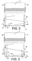
- FIGS. 2 and 3 schematically a thread tray on the surface of a cheese 3 is indicated.
- the cheese 3 is shown in each case in the upper part of the drawings.
- the Fig. 2 shows the situation with a so-called "full” traverse stroke. That is, in a traverse stroke whose reversal points 14 each lie directly in the region of the coil edges 15 of the cheese 3. In such a “full” traverse stroke of the yarn guide 7 is accelerated from its reversal point 14 each maximum.
- Such "full" traversing strokes therefore indicate, as in Fig. 2 indicated, each having a relatively short acceleration region 12. At this acceleration region 12 is followed by a much longer center region 13, in which the speed of the yarn guide 7 is largely constant.
- the acceleration of the yarn guide 7 at a shortened traverse stroke is significantly lower, which has an extremely positive effect on the thermal load of the drive 8. That is, in a traverse stroke, the reversal points 14 are spaced from the coil edges 15 of the cheese 3, there are acceleration regions 12 and deceleration regions 22, which are slightly longer than at maximum acceleration and thus to larger reversing radii of the running on the cheese 3 thread 9 lead at the However, such a reduced acceleration occurring power loss of the drive 8 is significantly smaller.
Landscapes
- Engineering & Computer Science (AREA)
- Textile Engineering (AREA)
- Microelectronics & Electronic Packaging (AREA)
- Winding Filamentary Materials (AREA)
- Replacing, Conveying, And Pick-Finding For Filamentary Materials (AREA)
- Spinning Or Twisting Of Yarns (AREA)
- Looms (AREA)
Description
Die Erfindung betrifft ein Verfahren und eine Vorrichtung zum Betreiben einer Spuleinrichtung einer Kreuzspulen herstellenden Textilmaschine gemäß dem Oberbegriff des Anspruches 1.The invention relates to a method and a device for operating a winding device of a cross-wound textile machine according to the preamble of
Es ist bekannt, dass, um auf einer Spuleinrichtung einer Textilmaschine Kreuzspulen herstellen zu können, wenigstens zwei Voraussetzungen erfüllt sein müssen.
Zum einen muss die Spule während des Aufwickelns des Fadens rotiert werden und zum anderen muss der auf die rotierende Spule auflaufende Faden durch eine Fadenverlegeeinrichtung, beispielsweise durch einen traversierbaren Fadenführer, längs der Rotationsachse der Spule changiert werden.It is known that in order to be able to produce cross-wound bobbins on a winding device of a textile machine, at least two prerequisites must be met.
On the one hand, the bobbin has to be rotated during the winding of the thread and, on the other hand, the thread running on the rotating bobbin has to be changed by a thread laying device, for example by a traversable thread guide, along the axis of rotation of the bobbin.
Derartige Fadenverlegeeinrichtungen mit einem traversierbaren Fadenführer sind in zahlreichen Ausführungsformen bekannt und beispielsweise in der
Während der Changierung beschreibt der auf der Mantelfläche der Kreuzspule abgelegte Faden im Bereich der Spulenflanken jeweils einen Radius, was zum Aufbau erhöhter Spulenflanken führt.
Das heißt, in den Bereichen der Spulenflanken der Kreuzspule, in denen die Bewegungsrichtung des Fadenführers umgekehrt wird (Umkehrstrecke), wird deutlich mehr Garn abgelegt als in den Bereichen, in denen sich der Fadenführer mit konstanter Geschwindigkeit bewegt.
Es kommt daher, wenn keine besondere Maßnahmen ergriffen werden, im Bereich der Spulenflanken der Kreuzspule zu Materialanhäufungen.During traversing, the thread deposited on the lateral surface of the cross-wound bobbin in each case describes a radius in the region of the coil flanks, which leads to the construction of elevated coil flanks.
That is, in the areas of the coil flanks of the cheese, in which the direction of movement of the thread guide is reversed (reversal distance), significantly more yarn is deposited than in the Areas where the thread guide moves at a constant speed.
It comes therefore, if no special measures are taken, in the region of the coil flanks of the cheese to material accumulations.
Bei frei programmierbaren Fadenverlegeeinrichtungen ist es daher üblich, den Verlege- oder Changierhub des Fadenführers so zu variieren, dass jeweils nur ein Teil der Changierhübe bis zur Spulenflanke erfolgt, während ein anderer Teil der Changierhübe bereits vor der Spulenflanke umgekehrt wird. Dieses als Atmung bezeichnete Variieren der Changierhübe ist in zahlreichen Literaturstellen beschrieben (z.B.:
Die Änderungen des Changierhubes erfolgen dabei in einem Bereich, der durch einen maximalen Changierhub und einen minimalen Changierhub bestimmt ist.
Vorzugsweise werden die aufeinander folgenden Changierhübe dabei derart geändert, dass nach einem verkürzten Changierhub ein verlängerter Changierhub und nach einem verlängerten Changierhub wieder ein verkürzter Changierhub erfolgt.
Auf diese Weise wird ein stabiler Spulenaufbau ohne Sattelbildung im Bereich der Spulenflanken erreicht.The changes of the traverse stroke take place in a range which is determined by a maximum traverse stroke and a minimum traverse stroke.
Preferably, the successive traverse strokes are changed such that after a shortened traverse stroke an extended traverse stroke and after a prolonged traverse stroke again a shortened traverse stroke.
In this way, a stable coil structure without saddle formation in the region of the coil edges is achieved.
Ein etwas anderes Verfahren zur Vermeidung hoher Spulenkanten, ist in der
Bei diesem bekannten Verfahren werden die Beschleunigung und die Verzögerung des Changierfadenführers derart gesteuert, dass sich die Länge der Umkehrstrecke des Fadenführers mit wachsendem Spulendurchmesser der Spule vergrößert.A slightly different method for avoiding high coil edges, is in the
In this known method, the acceleration and the deceleration of the traversing yarn guide are controlled such that increases the length of the return path of the yarn guide with increasing coil diameter of the coil.
Durch die
Bei diesem bekannten Verfahren wird die Beschleunigung und die Verzögerung des Fadenführers benutzt, um die Fadenablage zu beeinflussen.
Das heißt, durch definierte Ansteuerung des Fadenführerantriebes werden Beschleunigung und Verzögerung des Fadenführers derart gesteuert, dass sich die Länge der Umkehrstrecke des Fadens verändert. Aus dieser Veränderung der Länge der Umkehrstrecke resultiert, dass der Faden mit unterschiedlichen Winkeln zur Stirnseite der Spule hin abgelegt und damit bereits unmittelbar hinter dem Umkehrpunkt eine gleichmäßige Verteilung des Fadens erreicht wird.By the
In this known method, the acceleration and deceleration of the thread guide is used to influence the thread tray.
That is, by defined control of the thread guide drive acceleration and deceleration of the thread guide are controlled so that changes the length of the reversal path of the thread. The result of this change in the length of the reversal path is that the thread is deposited at different angles towards the front side of the spool and thus a uniform distribution of the thread is achieved immediately after the reversal point.
Wie vorstehend angedeutet, ist der Radius, den der abgelegte Faden auf der Mantelfläche der Kreuzspule im Bereich der Spulenflanken beschreibt, verantwortlich für den Aufbau der Spulenflanken.
Dieser sogenannte Umkehrradius wird von der Beschleunigung des Fadenführers, der Umfangsgeschwindigkeit der Spule sowie dem Abstand zwischen Fadenführer und Ablagepunkt des Fadens auf der Spule bestimmt und beeinflusst nicht nur die Masseverteilung in der Kreuzspule, sondern ist auch ein wesentlicher Einflussfaktor bei der Entstehung von sogenannten Abschlägen an den Spulenflanken.
Solche Abschläge behindern den ordnungsgemäßen Ablauf des Fadens von der Kreuzspule und stellen somit einen nicht akzeptierbaren Qualitätsmangel der Kreuzspule dar.
Zur Vermeidung von Abschlägen ist es daher notwendig, den Umkehrradius des Fadens, insbesondere im Bereich der Spulenflanken der Kreuzspule, unter einem Grenzwert zu halten, der wiederum von anderen textilen Parametern abhängig ist. Da beispielsweise der Abstand zwischen Fadenführer und Ablagepunkt des Fadens auf der Spule festgelegt sind, ist die einzige Möglichkeit zur Reduzierung des Umkehrradius eine Vergrößerung der Beschleunigung des Fadenführers.As indicated above, the radius which the deposited thread describes on the lateral surface of the cross-wound bobbin in the region of the coil flanks is responsible for the structure of the coil flanks.
This so-called reversal radius is determined by the acceleration of the thread guide, the peripheral speed of the coil and the distance between thread guide and storage point of the thread on the spool and not only affects the mass distribution in the cheese, but is also a major factor in the formation of so-called tees the coil edges.
Such deductions hinder the proper course of the thread from the cross-wound bobbin and thus represent an unacceptable quality defect of the cheese.
To avoid teeing it is therefore necessary, the radius of inversion of the thread, especially in the field of Spool flanks of the cheese to keep below a limit, which in turn depends on other textile parameters. For example, since the distance between yarn guide and storage point of the thread are set on the spool, the only way to reduce the radius of inversion is to increase the acceleration of the yarn guide.
Die bekannten Verfahren gehen dabei von der allgemein bekannten Tatsache aus, dass sich bei der Herstellung von Kreuzspulen auf Hochgeschwindigkeits-Spulmaschinen die Changierung des Fadens jeweils im wesentlichen aus einer kurzen Beschleunigungsphase nach dem einen Umkehrpunkt, einer Bewegung mit konstanter Geschwindigkeit in der Mitte der Spule sowie einer kurzen Verzögerungsphase vor dem anderen Umkehrpunkt zusammensetzt.
Die Beschleunigungs- und Verzögerungswerte des Fadens sind dabei an Umkehrpunkten sehr hoch, da die Fadenverlegung, je nach Prozessführung, mit Frequenzen von bis zu 30 Hz erfolgt.The known methods are based on the well-known fact that in the manufacture of cheeses on high-speed winder the traversing of the thread in each case essentially from a short acceleration phase after the one reversal point, a movement at a constant speed in the middle of the coil and a short delay phase before the other reversal point.
The acceleration and deceleration values of the thread are very high at reversal points, since the thread laying, depending on the process control, with frequencies of up to 30 Hz.
Des weiteren ist durch die
Der Antrieb des Fadenführers wird dabei, während sich der Fadenführer in der Nähe eines Umkehrpunktes befindet, mit einem Motorstrom beaufschlagt, der über dem Nennstrom liegt und im übrigen Bereich mit einem Motorstrom versorgt, der unterhalb des Nennstromes liegt.Furthermore, by the
The drive of the thread guide is, while the thread guide is near a reversal point, acted upon by a motor current which is above the rated current and supplies in the remaining area with a motor current which is below the rated current.
Bei einem Fadenführer, der durch einen elektromotorischen Antrieb, beispielsweise einen Gleichstrommotor, beaufschlagt wird, verhält sich die Beschleunigung des Fadenführers proportional zum zugeführten Motorstrom.
Gleichzeitig verhält sich die Verlustleistung eines solchen Motors, die in erster Linie in Form von Wärme freigesetzt wird, proportional zum Quadrat des Motorstromes.
Das bedeutet, die in den Beschleunigungsphasen des Fadenführers auftretende Verlustleistung ist zu einem überwiegenden Teil für die thermische Belastung des Antriebes verantwortlich.
Da solche elektromotorische Antriebe nach ihrer thermischen Belastbarkeit dimensioniert werden müssen, bestimmt folglich die Umkehrbeschleunigung des Fadenführers im wesentlichen die Baugröße und damit die Herstellkosten des einzusetzenden Motors.
Diese Aussage gilt jedoch nicht für jede einzelne Beschleunigungsphase, sondern wegen der großen Zeitkonstanten bei der Erwärmung des Motors für den Mittelwert der in den Beschleunigungsphasen entstehenden Verlustleistungen.In a yarn guide, the applied by an electric motor drive, such as a DC motor is, the acceleration of the thread guide behaves proportional to the supplied motor current.
At the same time, the power loss of such an engine, which is released primarily in the form of heat, is proportional to the square of the motor current.
This means that the power loss occurring in the acceleration phases of the yarn guide is responsible for a large part for the thermal load of the drive.
Since such electromotive drives must be dimensioned according to their thermal capacity, thus determines the reversal acceleration of the yarn guide essentially the size and thus the manufacturing cost of the motor to be used.
However, this statement does not apply to every single acceleration phase, but because of the large time constant in the heating of the motor for the average of the power losses resulting in the acceleration phases.
Ausgehend vom vorgenannten Stand der Technik liegt der Erfindung die Aufgabe zugrunde, ein Verfahren und eine Vorrichtung zu schaffen, das/die eine kostengünstige Dimensionierung eines elektromotorischen Fadenführerantriebes einer Spulvorrichtung ermöglicht, ohne dass dabei die Qualität der herzustellenden Kreuzspule negativ beeinflußt wird.Based on the above-mentioned prior art, the present invention seeks to provide a method and an apparatus that allows a cost-effective dimensioning of an electric motor thread guide drive a winder, without affecting the quality of the cheese to be produced is adversely affected.
Diese Aufgabe wird erfindungsgemäß durch ein Verfahren gelöst, wie es im Anspruch 1 beschrieben ist, beziehungsweise durch eine Vorrichtung nach Anspruch 5.This object is achieved by a method as described in
Vorteilhafte Ausführungsformen der Erfindung sind in den Unteransprüchen 2 bis 4 beziehungsweise 6 beschrieben.Advantageous embodiments of the invention are described in the
Das erfindungsgemäße Verfahren hat insbesondere den Vorteil, dass durch die spezielle steuerungstechnische Verknüpfung der Breite der Changierhübe mit der Beschleunigung des Fadenführers die mittlere thermische Belastung des Fadenführerantriebes erheblich gesenkt werden kann.
Das heißt, mit dem erfindungsgemäßen Verfahren ist es möglich, mit einem relativ kleinen Antrieb dort relativ hohe Beschleunigungswerte des Fadenführers zu realisieren, wo diese Beschleunigungswerte erforderlich sind, jedoch gleichzeitig sicherzustellen, dass trotz des Einsatzes eines kleinen und damit kostengünstigen Antriebes, dieser Fadenführerantrieb auch im Dauerbetrieb thermisch nicht überlastet wird. Erfindungsgemäß wird der Antrieb des Fadenführers nur bei Changierhüben, deren Umkehrpunkte im Bereich der Spulenflanken der Kreuzspule liegen, zur Erzielung einer maximalen Beschleunigung kurzfristig mit einem Motorstrom beaufschlagt, der dem 3- bis 6fachen, vorzugsweise dem 4fachen, des für einen dauerhaften Betrieb des Antriebes thermisch zulässigen Motorstromes entspricht.The inventive method has the particular advantage that the average thermal load of the thread guide drive can be significantly reduced by the special control technology link the width of the traverse strokes with the acceleration of the thread guide.
That is, with the method according to the invention, it is possible with a relatively small drive there to realize relatively high acceleration values of the thread guide, where these acceleration values are required, but at the same time to ensure that despite the use of a small and therefore cost-effective drive, this thread guide drive in the Continuous operation is not thermally overloaded. According to the invention, the drive of the yarn guide is briefly applied to traverse strokes whose reversal points in the coil flanks of the cheese to achieve maximum acceleration with a motor current of 3 to 6 times, preferably 4 times, the thermally for a permanent operation of the drive permissible motor current.
Bei verkürzten Changierhüben, bei denen mit reduzierter Beschleunigung des Fadenführers gearbeitet werden kann, beträgt der dem Fadenführerantrieb zugeführte Motorstrom dagegen etwa das 1,5- bis 2,5fache, vorzugsweise das 2fache, des für einen dauerhaften Betrieb des Antriebes thermisch zulässigen Motorstromes.
Da eine Vielzahl der während einer Spulenreise auszuführenden Changierhübe verkürzte Changierhübe mit reduzierter Beschleunigung des Fadenführers und entsprechend reduzierter Verlustleistung des Fadenführerantriebes sind, hält sich der für die thermische Belastung des elektromotorischen Antriebes maßgebende Mittelwert der Verlustleistungen in technisch beherrschbaren Grenzen.In the case of shortened traverse strokes, which can be carried out with reduced acceleration of the thread guide, the motor current supplied to the thread guide drive, however, is approximately 1.5 to 2.5 times, preferably 2 times, the motor current permissible for permanent operation of the drive.
Since a large number of the traverse strokes to be executed during a spool travel are shortened traverse strokes with reduced acceleration of the thread guide and correspondingly reduced power loss of the thread guide drive, the mean value of the power losses governing the thermal loading of the electromotive drive remains within technically controllable limits.
Das bedeutet, bei Anwendung des erfindungsgemäßen Verfahrens ist auch bei einem Einsatz eines relativ klein dimensionierten Fadenführerantriebes im Dauerbetrieb keine Überhitzung des Antriebes zu befürchten.This means that when using the method according to the invention, no overheating of the drive is to be feared even when using a relatively small dimensioned thread guide drive in continuous operation.
In vorteilhafter Ausführungsform ist, wie im Anspruch 2 dargelegt, vorgesehen, dass über die Steuereinrichtung zwei Beschleunigungswerte für den Fadenführer einstellbar sind.
Das heißt, ein erster maximaler Beschleunigungswert, wenn ein voller Changierhub gefahren wird, dessen Umkehrpunkte im Bereich der Spulenflanken der Kreuzspule liegen, sowie ein zweiter, reduzierter Beschleunigungswert bei verkürzten Changierhüben.
Eine solche Ausführungsform zeichnet sich insbesondere durch eine relativ einfache und damit kostengünstige Steuereinrichtung aus.In an advantageous embodiment, as set out in
That is, a first maximum acceleration value, when a full traverse stroke is traveled, the reversal points are in the range of the coil edges of the cheese, and a second, reduced acceleration value at shorter traversing strokes.
Such an embodiment is characterized in particular by a relatively simple and therefore cost-effective control device.
Etwas komplizierter wird die Steuereinrichtung, wenn, wie im Anspruch 3 beschrieben, außer mit einem maximalen Beschleunigungswert für volle Changierhübe, mit einerThe control device becomes somewhat more complicated if, as described in
Mehrzahl, zum Beispiel stufenweise auf die Breite verkürzter Changierhübe angepasster Beschleunigungswerte gearbeitet werden soll.
Eine solche vorteilhafte Ausführungsform macht sich allerdings durch einen noch gleichmäßigeren Spulenaufbau positiv bemerkbar.Plural, for example, gradually to the width of shortened traverse strokes adapted acceleration values to be worked.
However, such an advantageous embodiment makes itself felt positively by an even more uniform coil structure.
Eine Optimierung des Spulenaufbaues kann erreicht werden, wenn durch die Steuereinrichtung eine stufenlose Einstellung der Beschleunigungswerte des Fadenführers erfolgt (Anspruch 4). Das heißt, wenn jeweils in Abhängigkeit von der Breite des Changierhubes des Fadenführers eine stufenlose Anpassung des Beschleunigungswertes des Fadenführers erfolgt.An optimization of the coil structure can be achieved if a continuous adjustment of the acceleration values of the thread guide takes place by the control device (claim 4). That is, if in each case depending on the width of the Changierhubes the thread guide a continuous adjustment of the acceleration value of the thread guide takes place.
Die im Anspruch 5 beschriebene Vorrichtung zur Durchführung des erfindungsgemäßen Verfahrens weist einen Spulenrahmen zum rotierbaren Haltern einer Spule, einen elektromotorisch beaufschlagbaren Fadenführer sowie eine Steuereinrichtung zum definierten Ansteuern des Fadenführerantriebes auf.The device described in
Die Steuereinrichtung ist dabei so konzipiert, dass der Fadenführerantrieb, nur dann, wenn ein voller Changierhub ausgeführt werden soll, maximal beschleunigt. Das heißt, dass der Antrieb dann kurzzeitig mit einem Motorstrom beaufschlagt wird, der das 3- bis 6fache, vorzugsweise das 4fache, des für einen dauerhaften Betrieb des Antriebs thermisch zulässigen Motorstroms beträgt.The control device is designed so that the yarn guide drive, only when a full traverse stroke is to be executed, maximally accelerated. This means that the drive is then briefly subjected to a motor current which is 3 to 6 times, preferably 4 times, the motor current permissible for a permanent operation of the drive.
Bei allen verkürzten Changierhüben sorgt die Steuereinrichtung dagegen dafür, dass der zugeführte Motorstrom etwa um die Hälfte verringert wird, was sich hinsichtlich der Verlustleistung des Antriebes sofort signifikant auswirkt.For all shortened traverse strokes, however, the control device ensures that the supplied motor current is reduced by about half, which immediately has a significant effect on the power loss of the drive.
Das heißt, der Antrieb wird kurzzeitig mit einem Motorstrom beaufschlagt, der das 1,5- bis 2,5fache, vorzugsweise das 2fache, des für einen dauerhaften Betrieb des Antriebs thermisch zulässigen Motorstromes beträgt, wodurch die thermische Belastung des Fadenführerantriebes sofort erheblich abnimmt.That is, the drive is briefly acted upon by a motor current which is 1.5 to 2.5 times, preferably 2 times, the thermally permissible for a permanent operation of the drive motor current, whereby the thermal load of the thread guide drive immediately decreases significantly.
Wie im Anspruch 6 dargelegt, ist der Fadenführer in vorteilhafter Ausführungsform als Fingerfadenführer ausgebildet und um eine Achse, die im wesentlichen senkrecht zur Rotationsachse der Kreuzspule steht, schwenkbar gelagert.As set forth in
Der Fadenführerantrieb ist dabei vorzugsweise als elektromotorischer Einzelantrieb ausgebildet.
Derartige Fingerfadenführer zeichnen sich insbesondere durch ein relativ geringes Gewicht aus, was angesichts der Tatsache, dass solche Fadenführer durch den elektromotorischen Einzelantrieb mit einer Frequenz von ca. 30 Hz changiert werden, sehr wichtig ist.The thread guide drive is preferably designed as an electric motor single drive.
Such finger thread guides are characterized in particular by a relatively low weight, which is very important in view of the fact that such thread guides are oscillated by the electromotive single drive with a frequency of about 30 Hz.
Die Erfindung wird nachfolgend anhand eines in den Zeichnungen dargestellten Ausführungsbeispieles näher erläutert.The invention will be explained in more detail with reference to an embodiment shown in the drawings.
Es zeigt:
- Fig.1
- in Vorderansicht, schematisch eine Spuleinrichtung einer Kreuzspulen herstellenden Textilmaschine zur Durchführung des erfindungsgemäßen Verfahrens,
- Fig.2
- die Fadenablage auf der Oberfläche einer Kreuzspule bei einem Changierhub, dessen Umkehrpunkte im Bereich der Spulenflanken der Kreuzspule liegen,
- Fig.3
- die Fadenablage auf der Oberfläche einer Kreuzspule bei einem verkürzten Changierhub.
- Fig.1
- in front view, schematically a winding device of a cross-wound producing textile machine for carrying out the method according to the invention,
- Fig.2
- the yarn deposit on the surface of a cross-wound bobbin during a traverse stroke whose reversal points lie in the region of the coil flanks of the cross-wound bobbin,
- Figure 3
- the thread tray on the surface of a cheese with a shortened traverse stroke.
Die insgesamt mit der Bezugszahl 1 gekennzeichnete Spuleinrichtung verfügt über einen Spulenrahmen 2 zum rotierbaren Haltern einer Kreuzspule 3.
Das heißt, zwischen den Spulenrahmenarmen des Spulenrahmens 2 ist, wie üblich, eine Kreuzspule 3 rotierbar gelagert, die mit ihrer Oberfläche auf einer Antriebswalze 5 aufliegt und von dieser Antriebswalze 5 über Reibschluß mitgenommen wird.The winding device indicated overall by the
That is, between the coil frame arms of the
Die Antriebswalze 5 ist zu diesem Zweck an einen elektromotorischen Einzelantrieb 6 angeschlossen, der seinerseits über eine Steuerleitung 21 mit einer Steuereinrichtung 10 verbunden ist.The
Anstelle der dargestellten, die Kreuzspule 3 reibschlüssig antreibenden Antriebswalze 5, ist zum Rotieren der Kreuzspule 3 selbstverständlich auch eine andere Antriebsart denkbar. Die Kreuzspule 3 kann beispielsweise auch mittels eines (nicht dargestellten) Spindelantriebes, das heißt, eines Antriebes, der auf einen der die Kreuzspule tragenden Hülsenteller 21 wirkt, direkt angetrieben werden.
Ein solcher Spindelantrieb ist dann vorzugsweise in Höhe der Rotationsachse 4 der Kreuzspule 3 am Spulenrahmen 2 angeordnet.Instead of the illustrated, the
Such a spindle drive is then preferably arranged at the height of the axis of
Zur Changierung des auf die Kreuzspule 3 auflaufenden Fadens 9, der von einer nicht dargestellten Vorlagespule, vorzugsweise von einem Spinnkops abgewickelt wird, ist eine spezielle Fadenverlegeeinrichtung vorgesehen.For traversing the running on the
Die Fadenverlegeeinrichtung weist einen changierbaren Fadenführer, beispielsweise einen Fingerfadenführer 7 auf, der um eine Schwenkachse 20 begrenzt drehbar gelagert und mittels eines elektromotorischen Antriebes 8, vorzugsweise eines Gleichstrommotors, definiert verschwenkbar ist.
Wie ersichtlich, ist der elektromotorische Antrieb 8 zu diesem Zweck über eine Steuerleitung 11 an die Steuereinrichtung 10 angeschlossen. Am Antrieb 8 ist außerdem ein Winkelsensor 23 angebracht, der ebenfalls über eine Signalleitung 24 mit der Steuereinrichtung 10 verbunden ist.
Das bedeutet, über die Steuereinrichtung 10, die den Antrieb 8 des Fingerfadenführers 7 entsprechend ansteuert, können sowohl die Changierbreite der Verlegehübe als auch die Beschleunigung des Fadenführers 7 exakt eingestellt und jederzeit geändert werden.
Die maximalen Schwenkwege des Fadenführers 7 während eines Doppelhubes sind in der
As can be seen, the
This means, via the
The maximum pivoting paths of the
In den
Die Kreuzspule 3 ist dabei jeweils im oberen Teil der Zeichnungen dargestellt.The
Die
Das heißt, bei einem Changierhub, dessen Umkehrpunkte 14 jeweils direkt im Bereich der Spulenflanken 15 der Kreuzspule 3 liegen.
Bei einem solchen "vollen" Changierhub wird der Fadenführer 7 aus seinen Umkehrpunkt 14 heraus jeweils maximal beschleunigt. Solche "volle" Changierhübe weisen daher, wie in
An diesen Beschleunigungsbereich 12 schließt sich ein deutlich längerer Mittelbereich 13 an, in dem die Geschwindigkeit des Fadenführers 7 weitestgehend konstant ist.
In einem anschließenden Verzögerungsbereich 22 wird der Fadenführer 7 durch seinen Antrieb 8 wieder bis auf die Geschwindigkeit "Null" heruntergebremst, die er am zweiten Umkehrpunkt 14 erreicht, um anschließend, wenn zum Beispiel noch ein "voller" Changierhub ansteht, sofort wieder maximal beschleunigt zu werden.The
That is, in a traverse stroke whose reversal points 14 each lie directly in the region of the coil edges 15 of the
In such a "full" traverse stroke of the
At this
In a
Wie in
Das heißt, bei einem Changierhub, dessen Umkehrpunkte 14 beabstandet zu den Spulenflanken 15 der Kreuzspule 3 liegen, ergeben sich Beschleunigungsbereiche 12 bzw. Verzögerungsbereiche 22, die zwar etwas länger sind als bei maximaler Beschleunigung und damit zu größeren Umkehrradien des auf die Kreuzspule 3 auflaufenden Fadens 9 führen, die bei einer solchen reduzierten Beschleunigung auftretende Verlustleistung des Antriebes 8 ist aber signifikant kleiner.As in
That is, in a traverse stroke, the reversal points 14 are spaced from the coil edges 15 of the
Da sich die Beschleunigung des Fadenführers, wie eingangs erläutert, proportional zum Motorstrom verhält, der seinem Antrieb zugeführt wird, die während der Beschleunigung auftretende Verlustleistung jedoch gleichzeitig proportional zum Quadrat des zugeführten Motorstromes steigt, lässt sich durch eine Reduzierung der Beschleunigung in Spulenbereichen, die nicht so empfindlich auf eine verminderte Fadenführerbeschleunigung reagieren, auf relativ einfache Weise die Verlustleistung eines solchen Antriebes vermindern und damit die thermische Belastung des Antriebes im Mittelwert deutlich reduzieren.Since the acceleration of the thread guide, as explained above, proportional to the motor current is supplied to its drive, but the power dissipation occurring during acceleration increases simultaneously proportional to the square of the supplied motor current, can be reduced by reducing the acceleration in coil areas, not react so sensitive to a reduced yarn guide acceleration, relatively easily reduce the power loss of such a drive and thus significantly reduce the thermal load of the drive in the average.
Claims (6)
- Method for operating a winding device of a textile machine for producing cross wound bobbins, comprising a bobbin frame for rotatably mounting a bobbin and an electric motor driven thread guide, which traverses a thread running onto the bobbin during the winding, and a control device for driving the thread guide, which enables a defined setting of the width of the traversing strokes of the thread guide and the acceleration of the thread guide,
characterised in that
the acceleration of the thread guide (7) is dependent on the width of the traversing strokes, whereby the electric motor drive (8) of the thread guide (7) is controlled by means of the control device (10) such that the thread guide (7) is subjected to maximum acceleration only with traversing strokes, the reversing points (14) of which are in the region the bobbin sides (15) of the cross wound bobbin (3), this means it is charged briefly with a motor current, which is 3 to 6 times, preferably 4 times, the thermally permissible motor current for a long-term operation of the drive (8), whereas with shortened traversing strokes there is a reduced acceleration of the thread guide (7), in which the drive (8) is charged briefly with a motor current, which is 1.5 to 2.5 times, preferably twice, the thermally permissible motor current for long-term operation of the drive (8). - Method according to claim 1, characterised in that by means of the control device (10) two acceleration values are set for the thread guide (7), a maximum acceleration value for traversing strokes, whose reversing points (14) are on the sides (15) of the cross wound bobbin (3) and a reduced acceleration value for shortened traversing strokes.
- Method according to claim 1, characterised in that by means of the control device (10) in addition to a maximum acceleration value with traversing strokes, the reversing points (14) of which are on the sides (15) of the cross wound bobbin (3), in stages a plurality of reduced acceleration values adapted to the width of shortened traversing strokes is adjusted.
- Method according to claim 1, characterised in that by means of the control device (10) there is a stepless adjustment of the acceleration values, as a function of the traversing stroke.
- Device for performing the method according to claim 1, characterised in that the thread guide (7) comprises an electric motor drive (8), which can be controlled by the control device (10), which is designed such that the thread guide (7) is subjected to maximum acceleration only with traversing strokes whose reversing points (14) are in the region of the sides (15) of the cross wound bobbin (3), in which the drive (8) is charged briefly with a motor current which is 3 to 6 times, preferably 4 times, the thermally permissible motor current for the long-term operation of the drive (8), whereas the acceleration of the thread guide (7) with shortened traversing strokes is reduced significantly relative to the maximum acceleration, and in that the drive (8) is charged briefly with a motor current which is 1.5 to 2.5 times, preferably twice, the thermally permissible motor current for a long-term operation of the drive (8).
- Device according to claim 5, characterised in that the thread guide is designed as a finger thread guide (7), in that the finger thread guide (7) is mounted pivotably about an axis (20) oriented substantially perpendicular to the rotational axis (4) of the drivable cross wound bobbin (3), and in that the finger thread guide (7) can be charged by an independent electric motor drive (8).
Applications Claiming Priority (2)
| Application Number | Priority Date | Filing Date | Title |
|---|---|---|---|
| DE200410025519 DE102004025519A1 (en) | 2004-05-25 | 2004-05-25 | Method and device for operating a winding device of a cross-wound producing textile machine |
| DE102004025519 | 2004-05-25 |
Publications (3)
| Publication Number | Publication Date |
|---|---|
| EP1600414A2 EP1600414A2 (en) | 2005-11-30 |
| EP1600414A3 EP1600414A3 (en) | 2009-04-15 |
| EP1600414B1 true EP1600414B1 (en) | 2010-10-13 |
Family
ID=34975207
Family Applications (1)
| Application Number | Title | Priority Date | Filing Date |
|---|---|---|---|
| EP20050002240 Not-in-force EP1600414B1 (en) | 2004-05-25 | 2005-02-03 | Method and apparatus for operating a winding machine producing crosswound bobbins |
Country Status (4)
| Country | Link |
|---|---|
| EP (1) | EP1600414B1 (en) |
| JP (1) | JP2005335954A (en) |
| CN (1) | CN1702031B (en) |
| DE (2) | DE102004025519A1 (en) |
Cited By (2)
| Publication number | Priority date | Publication date | Assignee | Title |
|---|---|---|---|---|
| DE102013225653A1 (en) | 2013-12-11 | 2015-06-11 | Schaeffler Technologies AG & Co. KG | Thread traversing device and method for operating a thread traversing device |
| DE102014202888A1 (en) | 2014-02-18 | 2015-08-20 | Schaeffler Technologies AG & Co. KG | Coil winder |
Families Citing this family (11)
| Publication number | Priority date | Publication date | Assignee | Title |
|---|---|---|---|---|
| CN101289150B (en) * | 2008-04-18 | 2012-02-22 | 欧瑞康纺织有限及两合公司 | Coiling apparatus of workstation for producing loom of cross wound bobbin |
| CN101618809B (en) * | 2009-07-20 | 2012-02-22 | 南京航空航天大学 | Device for controlling yarn releasing with low damage and method |
| DE102011105559B4 (en) * | 2011-06-25 | 2019-03-14 | Saurer Spinning Solutions Gmbh & Co. Kg | Thread guide element for a finger thread guide |
| DE102015009191A1 (en) * | 2015-07-16 | 2017-01-19 | Saurer Germany Gmbh & Co. Kg | Method for producing a cross-wound bobbin |
| DE102016115732A1 (en) | 2016-08-24 | 2018-03-01 | Saurer Germany Gmbh & Co. Kg | Thread splicing device for a workstation of a cross-wound textile machine |
| DE102016119542A1 (en) | 2016-10-13 | 2018-04-19 | Saurer Germany Gmbh & Co. Kg | Thread splicing device for a workstation of a cross-wound textile machine |
| DE102017129582A1 (en) | 2017-12-12 | 2019-06-13 | Saurer Spinning Solutions Gmbh & Co. Kg | Yarn splicing device for a textile machine |
| WO2020075383A1 (en) * | 2018-10-09 | 2020-04-16 | Tmtマシナリー株式会社 | Yarn winding device and yarn winding method |
| CN111056371A (en) * | 2020-01-14 | 2020-04-24 | 曹超铨 | Uniform yarn guide device of winder reciprocating along with winding process |
| CN111517153B (en) * | 2020-04-21 | 2022-11-08 | 浙江华洋休闲用品有限公司 | Adjusting mechanism of textile production weaving frame |
| CN111472159B (en) * | 2020-05-09 | 2021-09-03 | 苏州基列德智能制造有限公司 | Fixed-length detection method and system for textile equipment and storage medium |
Family Cites Families (10)
| Publication number | Priority date | Publication date | Assignee | Title |
|---|---|---|---|---|
| US2388557A (en) * | 1943-09-21 | 1945-11-06 | Textron Inc | Means for winding textile packages |
| US4771960A (en) * | 1985-02-20 | 1988-09-20 | Teijin Seiki Co., Ltd. | Method for winding a cross-wound package |
| DE59008484D1 (en) * | 1990-04-23 | 1995-03-23 | Ssm Ag | Method and device for winding a thread on a spool. |
| CH681450A5 (en) * | 1990-05-18 | 1993-03-31 | Rieter Ag Maschf | |
| TW368490B (en) * | 1997-02-27 | 1999-09-01 | Barmag Barmer Maschf | Method of and apparatus for winding a continuously advancing textile yarn into a core supported package by controlling the acceleration and/or deceleration of the yarn guide to modify the yarn deposit in the package edges |
| DE19960024A1 (en) * | 1998-12-18 | 2000-06-21 | Schlafhorst & Co W | Reciprocating yarn guide for cross wound bobbin winding has an electromechanical drive and springs on adjustable suspensions to store energy at the dead points for smooth to and fro movements |
| DE19858548A1 (en) * | 1998-12-18 | 2000-06-21 | Schlafhorst & Co W | Electromechanical drive for the reciprocating yarn guide for winding cross wound bobbins has a structured air gap with magnetic field lines through it acting on a coil at the yarn guide |
| EP1125877A1 (en) * | 2000-02-17 | 2001-08-22 | Schärer Schweiter Mettler AG | Winding head and its use |
| DE10040106A1 (en) * | 2000-08-17 | 2002-02-28 | Schlafhorst & Co W | Winding device for a textile machine producing cross-wound bobbins |
| JP4078879B2 (en) * | 2002-05-23 | 2008-04-23 | 村田機械株式会社 | Traverse control device |
-
2004
- 2004-05-25 DE DE200410025519 patent/DE102004025519A1/en not_active Withdrawn
-
2005
- 2005-02-03 DE DE200550010373 patent/DE502005010373D1/en active Active
- 2005-02-03 EP EP20050002240 patent/EP1600414B1/en not_active Not-in-force
- 2005-05-23 JP JP2005149995A patent/JP2005335954A/en active Pending
- 2005-05-25 CN CN 200510074043 patent/CN1702031B/en active Active
Cited By (2)
| Publication number | Priority date | Publication date | Assignee | Title |
|---|---|---|---|---|
| DE102013225653A1 (en) | 2013-12-11 | 2015-06-11 | Schaeffler Technologies AG & Co. KG | Thread traversing device and method for operating a thread traversing device |
| DE102014202888A1 (en) | 2014-02-18 | 2015-08-20 | Schaeffler Technologies AG & Co. KG | Coil winder |
Also Published As
| Publication number | Publication date |
|---|---|
| EP1600414A2 (en) | 2005-11-30 |
| DE502005010373D1 (en) | 2010-11-25 |
| EP1600414A3 (en) | 2009-04-15 |
| JP2005335954A (en) | 2005-12-08 |
| CN1702031B (en) | 2011-01-12 |
| DE102004025519A1 (en) | 2005-12-15 |
| CN1702031A (en) | 2005-11-30 |
Similar Documents
| Publication | Publication Date | Title |
|---|---|---|
| EP1600414B1 (en) | Method and apparatus for operating a winding machine producing crosswound bobbins | |
| EP1159217B1 (en) | Thread guide for traversing a thread in a rotating winding bobbin | |
| DE68907875T2 (en) | Method for checking the thread guidance on a winder in a winding device for synthetic threads. | |
| DE19807030A1 (en) | Bobbin winding of continuous yarn | |
| EP0165511A2 (en) | Device for winding a yarn supplied at a constant speed on a conical spool | |
| DE102006004894A1 (en) | Auxiliary thread guide for traversing a running thread in the region of a thread withdrawal device of a cheese-producing textile machine | |
| EP1625091B2 (en) | Strip winding method | |
| EP1124748B1 (en) | Yarn changing method | |
| WO2007057109A1 (en) | Method for avoiding ribbon windings | |
| WO2000068126A2 (en) | Method and device for winding a continuously fed thread | |
| WO2005095246A1 (en) | Method for winding a thread, and winding machine | |
| DE19921630A1 (en) | Traverse drive for winding cross-wound packages uses a linear electric motor | |
| EP0386519B1 (en) | Method and device for winding a predetermined length of yarn in layers on a bobbin | |
| DE10342266B4 (en) | Method for producing a cross-wound bobbin | |
| WO2009030592A1 (en) | Changing device | |
| EP0294408B1 (en) | Cross-winding device | |
| DE10020664A1 (en) | Method for operating a textile machine producing cross-wound bobbins | |
| EP1222133B1 (en) | Method and device for winding a thread onto a bobbin | |
| DE19829597A1 (en) | Method for operating a textile machine producing cross-wound bobbins | |
| EP0248856B1 (en) | Winding-on machine | |
| EP0997422B1 (en) | Yarn guide device | |
| DE4121781A1 (en) | GEARBOX FOR TEXTILE MACHINES, IN PARTICULAR TO PREVENT IMAGE WINDINGS WHEN FINDING THREADS | |
| EP1125879A2 (en) | Device for producing a thread reserve and/or an end ridge of thread | |
| DE4024218A1 (en) | Cross wound bobbin winding - uses selected opening and final valves for yarn crossing angle and winding ratio from initial wound layer to last layer | |
| DE102015222045B3 (en) | Cross-winding device |
Legal Events
| Date | Code | Title | Description |
|---|---|---|---|
| PUAI | Public reference made under article 153(3) epc to a published international application that has entered the european phase |
Free format text: ORIGINAL CODE: 0009012 |
|
| AK | Designated contracting states |
Kind code of ref document: A2 Designated state(s): AT BE BG CH CY CZ DE DK EE ES FI FR GB GR HU IE IS IT LI LT LU MC NL PL PT RO SE SI SK TR |
|
| AX | Request for extension of the european patent |
Extension state: AL BA HR LV MK YU |
|
| RAP1 | Party data changed (applicant data changed or rights of an application transferred) |
Owner name: OERLIKON TEXTILE GMBH & CO. KG |
|
| RAP1 | Party data changed (applicant data changed or rights of an application transferred) |
Owner name: OERLIKON TEXTILE GMBH & CO. KG |
|
| PUAL | Search report despatched |
Free format text: ORIGINAL CODE: 0009013 |
|
| AK | Designated contracting states |
Kind code of ref document: A3 Designated state(s): AT BE BG CH CY CZ DE DK EE ES FI FR GB GR HU IE IS IT LI LT LU MC NL PL PT RO SE SI SK TR |
|
| AX | Request for extension of the european patent |
Extension state: AL BA HR LV MK YU |
|
| 17P | Request for examination filed |
Effective date: 20091015 |
|
| AKX | Designation fees paid |
Designated state(s): CH DE FR IT LI TR |
|
| 17Q | First examination report despatched |
Effective date: 20091216 |
|
| GRAP | Despatch of communication of intention to grant a patent |
Free format text: ORIGINAL CODE: EPIDOSNIGR1 |
|
| GRAS | Grant fee paid |
Free format text: ORIGINAL CODE: EPIDOSNIGR3 |
|
| GRAA | (expected) grant |
Free format text: ORIGINAL CODE: 0009210 |
|
| AK | Designated contracting states |
Kind code of ref document: B1 Designated state(s): CH DE FR IT LI TR |
|
| REG | Reference to a national code |
Ref country code: CH Ref legal event code: EP |
|
| REF | Corresponds to: |
Ref document number: 502005010373 Country of ref document: DE Date of ref document: 20101125 Kind code of ref document: P |
|
| PLBE | No opposition filed within time limit |
Free format text: ORIGINAL CODE: 0009261 |
|
| STAA | Information on the status of an ep patent application or granted ep patent |
Free format text: STATUS: NO OPPOSITION FILED WITHIN TIME LIMIT |
|
| 26N | No opposition filed |
Effective date: 20110714 |
|
| REG | Reference to a national code |
Ref country code: DE Ref legal event code: R097 Ref document number: 502005010373 Country of ref document: DE Effective date: 20110714 |
|
| REG | Reference to a national code |
Ref country code: FR Ref legal event code: ST Effective date: 20111102 |
|
| PG25 | Lapsed in a contracting state [announced via postgrant information from national office to epo] |
Ref country code: FR Free format text: LAPSE BECAUSE OF NON-PAYMENT OF DUE FEES Effective date: 20110228 |
|
| PGFP | Annual fee paid to national office [announced via postgrant information from national office to epo] |
Ref country code: TR Payment date: 20120203 Year of fee payment: 8 |
|
| REG | Reference to a national code |
Ref country code: CH Ref legal event code: NV Representative=s name: SCHMAUDER AND PARTNER AG PATENT- UND MARKENANW, CH Ref country code: CH Ref legal event code: PUE Owner name: SAURER GERMANY GMBH AND CO. KG, DE Free format text: FORMER OWNER: OERLIKON TEXTILE GMBH AND CO. KG, DE |
|
| REG | Reference to a national code |
Ref country code: DE Ref legal event code: R081 Ref document number: 502005010373 Country of ref document: DE Owner name: SAURER GERMANY GMBH & CO. KG, DE Free format text: FORMER OWNER: OERLIKON TEXTILE GMBH & CO. KG, 42897 REMSCHEID, DE Effective date: 20130918 |
|
| REG | Reference to a national code |
Ref country code: CH Ref legal event code: PCOW Free format text: NEW ADDRESS: LEVERKUSER STRASSE 65, 42897 REMSCHEID (DE) |
|
| PG25 | Lapsed in a contracting state [announced via postgrant information from national office to epo] |
Ref country code: TR Free format text: LAPSE BECAUSE OF NON-PAYMENT OF DUE FEES Effective date: 20130203 |
|
| PGFP | Annual fee paid to national office [announced via postgrant information from national office to epo] |
Ref country code: DE Payment date: 20160229 Year of fee payment: 12 |
|
| REG | Reference to a national code |
Ref country code: DE Ref legal event code: R119 Ref document number: 502005010373 Country of ref document: DE |
|
| PG25 | Lapsed in a contracting state [announced via postgrant information from national office to epo] |
Ref country code: DE Free format text: LAPSE BECAUSE OF NON-PAYMENT OF DUE FEES Effective date: 20170901 |
|
| PGFP | Annual fee paid to national office [announced via postgrant information from national office to epo] |
Ref country code: IT Payment date: 20190228 Year of fee payment: 15 Ref country code: CH Payment date: 20190222 Year of fee payment: 15 |
|
| REG | Reference to a national code |
Ref country code: CH Ref legal event code: PL |
|
| PG25 | Lapsed in a contracting state [announced via postgrant information from national office to epo] |
Ref country code: CH Free format text: LAPSE BECAUSE OF NON-PAYMENT OF DUE FEES Effective date: 20200229 Ref country code: LI Free format text: LAPSE BECAUSE OF NON-PAYMENT OF DUE FEES Effective date: 20200229 |
|
| PG25 | Lapsed in a contracting state [announced via postgrant information from national office to epo] |
Ref country code: IT Free format text: LAPSE BECAUSE OF NON-PAYMENT OF DUE FEES Effective date: 20200203 |