WO2020075383A1 - Yarn winding device and yarn winding method - Google Patents
Yarn winding device and yarn winding method Download PDFInfo
- Publication number
- WO2020075383A1 WO2020075383A1 PCT/JP2019/031771 JP2019031771W WO2020075383A1 WO 2020075383 A1 WO2020075383 A1 WO 2020075383A1 JP 2019031771 W JP2019031771 W JP 2019031771W WO 2020075383 A1 WO2020075383 A1 WO 2020075383A1
- Authority
- WO
- WIPO (PCT)
- Prior art keywords
- traverse
- reversal
- guide
- traverse guide
- yarn
- Prior art date
Links
Images


Classifications
-
- B—PERFORMING OPERATIONS; TRANSPORTING
- B65—CONVEYING; PACKING; STORING; HANDLING THIN OR FILAMENTARY MATERIAL
- B65H—HANDLING THIN OR FILAMENTARY MATERIAL, e.g. SHEETS, WEBS, CABLES
- B65H54/00—Winding, coiling, or depositing filamentary material
- B65H54/02—Winding and traversing material on to reels, bobbins, tubes, or like package cores or formers
- B65H54/38—Arrangements for preventing ribbon winding ; Arrangements for preventing irregular edge forming, e.g. edge raising or yarn falling from the edge
- B65H54/381—Preventing ribbon winding in a precision winding apparatus, i.e. with a constant ratio between the rotational speed of the bobbin spindle and the rotational speed of the traversing device driving shaft
-
- B—PERFORMING OPERATIONS; TRANSPORTING
- B65—CONVEYING; PACKING; STORING; HANDLING THIN OR FILAMENTARY MATERIAL
- B65H—HANDLING THIN OR FILAMENTARY MATERIAL, e.g. SHEETS, WEBS, CABLES
- B65H54/00—Winding, coiling, or depositing filamentary material
- B65H54/02—Winding and traversing material on to reels, bobbins, tubes, or like package cores or formers
- B65H54/38—Arrangements for preventing ribbon winding ; Arrangements for preventing irregular edge forming, e.g. edge raising or yarn falling from the edge
- B65H54/385—Preventing edge raising, e.g. creeping arrangements
-
- B—PERFORMING OPERATIONS; TRANSPORTING
- B65—CONVEYING; PACKING; STORING; HANDLING THIN OR FILAMENTARY MATERIAL
- B65H—HANDLING THIN OR FILAMENTARY MATERIAL, e.g. SHEETS, WEBS, CABLES
- B65H2701/00—Handled material; Storage means
- B65H2701/30—Handled filamentary material
- B65H2701/31—Textiles threads or artificial strands of filaments
Definitions
- the present invention relates to a yarn winding machine and a yarn winding method.
- Patent Document 1 discloses a yarn winding machine that winds a yarn around a bobbin while traversing the yarn with a traverse guide to form a package.
- the yarn winding machine includes a bobbin driving motor that rotationally drives the bobbin, a guide driving mechanism that causes the traverse guide to travel back and forth by the guide driving motor, and a control unit that controls the bobbin driving motor and the guide driving motor.
- One of the winding methods of the yarn in such a yarn winding machine is a "precision winding" method in which the ratio (wind ratio) between the number of revolutions of the bobbin and the number of traverses per unit time is controlled to be constant.
- the wind ratio is generally set to a value that is slightly different from an integer so that ribbon winding does not occur (no repeated winding of the yarn on the same path on the package surface).
- Patent Document 2 discloses a traverse device capable of performing creeping for suppressing the height of the ear of the package.
- Ear height is because it is generally difficult to rapidly reverse (direction change) the traverse guide, and the amount of yarn wound around the axial end of the package surface is greater than the amount of yarn wound around other parts. It will be many.
- the ear height may cause deterioration of the package shape and / or non-uniformity of the package density. Creeping refers to temporarily narrowing the width of the reciprocating region of the traverse guide (traverse width) during package formation. As a result, as compared with the case where creeping is not performed, the amount of yarn wound around the axial end portion of the package is reduced, and the ear height is reduced.
- the object of the present invention is to suppress the fluctuation of the wind ratio and the disturbance of the shape of the package surface even if creeping is performed during the execution of precision winding.
- the yarn winding machine of the first invention is capable of winding a running yarn on a rotating bobbin while traversing the traveling traverse guide, and the number of revolutions of the bobbin and the number of reciprocating movements of the traverse guide per unit time.
- a yarn winding machine configured to form a package while performing a precision winding for maintaining a constant wind ratio, which is a yarn winding operation for reciprocally driving the traverse guide in a predetermined traverse direction.
- a guide driving unit capable of changing the reverse position of the traverse guide and a control unit are provided therein, and the control unit controls the guide driving unit to move outward at a predetermined speed in the traverse direction.
- the idling drive unit is controlled to decelerate the traverse guide traveling outward at the predetermined speed in the traverse direction to invert at a second reversal position inside the first reversal position.
- the second reversal control for reaccelerating to the predetermined speed can be executed, and during the execution of the precision winding, the time from the deceleration start of the traverse guide to the reacceleration completion in the first reversal control can be performed.
- the second reversal time which is the time from the start of deceleration of the traverse guide to the completion of reacceleration in the second reversal control, is made longer than a certain first reversal time.
- the traverse guide is reversed at the first reverse position (hereinafter also referred to as normal time) and at the second reverse position (hereinafter, during creeping). Also called), it is necessary to make the wind ratio equal.
- the traverse guide movement period is set to be equal to the normal time even during creeping when the width of the traverse guide movement area is narrower than in the normal time.
- the second inversion time is longer than the first inversion time.
- the traveling speed of the traverse guide can be made equal between the normal time and the creeping at timings other than the reversal timing. it can. Therefore, the angles of the yarn wound around the package surface can be made uniform. Therefore, it is possible to prevent the shape of the package surface from being disturbed.
- the control unit in the first invention, in the second inversion control, has a longer distance between the first inversion position and the second inversion position in the traverse direction.
- the width of the region in which the traverse guide moves in the traverse direction is widened within the second inversion time.
- the longer the distance between the first reversal position and the second reversal position (that is, the narrower the traverse width during creeping) is, 2 It is necessary to lengthen the reversal time.
- the width of the region in which the traverse guide moves in the traverse direction within the second reversal time (hereinafter referred to as the reversal region) is constant, if the second reversal time becomes long, the traverse guide causes the second reversal control. Occasionally, it will remain in the area near the second reversal position for a long time. Then, the yarn is likely to be intensively wound around the narrow area on the surface of the package. As a result, the surface of the package is likely to have a step, and the yarn may fall off, which may adversely affect the shape of the package.
- the longer the distance between the first reversal position and the second reversal position the wider the reversal region. That is, when the second reversal time becomes long due to the narrowing of the traverse width during creeping, the region where the traverse guide can move during the second reversal control becomes wider. Therefore, it is possible to prevent the traverse guide from being continuously positioned for a long time within a narrow area in the traverse direction. Therefore, it is possible to prevent the yarn from being intensively wound in a narrow area on the surface of the package.
- the control unit starts deceleration of the traverse guide for half the second reversal time.
- the guide drive unit is controlled so that the traverse guide is positioned at the second reversal position in the traverse direction when time passes.
- the traverse guide can be rapidly decelerated to reach the second reversal position, and then gradually re-accelerated.
- the shape of the inverted portion of the yarn wound around the package surface may be significantly different between when the traverse guide is decelerated and when it is re-accelerated.
- the shape of the reverse portion of the yarn on the package surface becomes asymmetric, and the reverse portion may not be formed cleanly.
- the time from the start of deceleration of the traverse guide until the traverse guide reaches the second inversion position is equal to the time from the departure of the traverse guide from the second inversion position to the completion of reacceleration. can do.
- the shape of the inverted portion of the yarn can be made symmetrical with respect to the center axis of the package (that is, the inverted portion can be formed neatly). Therefore, it is possible to suppress the disorder of the shape of the inverted portion of the package surface.
- the yarn winding machine of a fourth invention is the yarn winding machine of any one of the first to third inventions, further comprising a bobbin drive unit that rotationally drives the bobbin, and the control unit controls the rotation angle of the bobbin and the traverse guide.
- a storage unit that stores information about a relationship with a position in the traverse direction, and controls the bobbin drive unit and the guide drive unit based on the information stored in the storage unit. Is.
- the yarn winding machine of the fifth invention is characterized in that, in any one of the first to fourth inventions, the guide drive unit has a drive source configured to be capable of forward and reverse drive.
- a motor that rotates in one direction is used as a drive source, and the structure for performing creeping is a complicated mechanical structure. For this reason, it is difficult for the cam type traverse device to perform fine control of creeping.
- the traverse guide can be made to travel back and forth by the forward and reverse drive of the drive source. Therefore, the position and timing of reversal of the traverse guide can be finely controlled by the control unit. Therefore, fine control of creeping can be easily performed.
- a yarn winding machine is characterized in that, in the fifth aspect, the guide drive unit includes a belt member to which the traverse guide is attached and which is reciprocally driven by the drive source. .
- the traverse guide travels back and forth in an arc. Therefore, even if precision winding is performed, it may be difficult to regularly wind the yarn around the package surface.
- the portion of the belt member to which the traverse guide is attached is stretched linearly and is reciprocally driven, so that the traverse guide can be easily linearly reciprocated. Therefore, it is possible to easily and regularly wind the yarn around the package surface.
- the running yarn is wound around a rotating bobbin while being traversed by a traverse guide, and the ratio of the number of revolutions of the bobbin to the number of reciprocating movements of the traverse guide per unit time is calculated.
- a yarn winding method for forming a package while performing precision winding for maintaining a certain wind ratio constant by decelerating the traverse guide running outward at a predetermined speed in a predetermined traverse direction
- the first reversal time which is the time from the deceleration start of the traverse guide to the re-acceleration completion in the first reversing step.
- the second reversal time which is the time until the completion of reacceleration, is lengthened.
- the present invention even if creeping is performed during the execution of precision winding, it is possible to suppress the fluctuation of the wind ratio and to prevent the shape of the package surface from being disturbed.
- (A) is a graph which shows the relationship between the speed of a traverse guide and time
- (b) is explanatory drawing which shows the path
- (A) is a graph showing the relationship between the position of the traverse guide and time
- (b) is a graph showing the relationship between the speed of the traverse guide and time.
- (A) is a graph showing the relationship between the acceleration of the traverse guide and time
- (b) is a graph showing the relationship between the width of the reversal region and the creeping amount.
- (A) And (b) is explanatory drawing which shows the path
- (A) is a graph which shows the relationship between the position of a traverse guide and time which concerns on a modification
- (b) is a graph which similarly shows the relationship between the speed of a traverse guide and time
- 11 is a graph showing a relationship between acceleration of the traverse guide and time according to the modified example shown in FIG. 10.
- the vertical direction and the horizontal direction shown in FIG. 1 are the vertical direction and the horizontal direction of the rewinder 1, respectively.
- the direction orthogonal to both the up-down direction and the left-right direction is the front-back direction.
- the traveling direction of the yarn Y is referred to as a yarn traveling direction.
- FIG. 1 is a schematic view of the rewinder 1 viewed from the front.
- the rewinder 1 includes a yarn supplying unit 11, a winding unit 12, a control device 13 (control unit of the present invention), and the like.
- the rewinder 1 unwinds the yarn Y from the yarn supplying package Ps supported by the yarn supplying unit 11, rewinds the yarn Y onto the winding bobbin Bw (bobbin of the present invention) by the winding unit 12, and the winding package Pw (book).
- the invention package). More specifically, the rewinder 1 is, for example, for rewinding the yarn Y wound around the yarn supplying package Ps more neatly, or forming a winding package Pw having a desired density.
- the yarn feeder 11 is attached to the front surface of the lower part of the machine stand 14 that is erected, for example.
- the yarn supplying unit 11 is configured to support a yarn supplying package Ps formed by winding a yarn Y on a yarn supplying bobbin Bs. Thereby, the yarn supplying section 11 can supply the yarn Y.
- the winding unit 12 is for winding the yarn Y on the winding bobbin Bw to form a winding package Pw.
- the winding unit 12 is provided on the upper portion of the machine base 14.
- the winding unit 12 includes a cradle arm 21, a winding motor 22 (bobbin driving unit of the present invention), a traverse device 23, a contact roller 24, and the like.
- the cradle arm 21 is swingably supported by the machine base 14, for example.
- the cradle arm 21 rotatably supports the take-up bobbin Bw with the left-right direction as the axial direction of the take-up bobbin Bw.
- a bobbin holder (not shown) that holds the take-up bobbin Bw is rotatably attached to the tip of the cradle arm 21.
- the winding motor 22 is for rotating and driving the bobbin holder.
- the winding motor 22 is, for example, a general AC motor, and is configured to be able to change the rotation speed. Accordingly, the winding motor 22 can change the rotation speed of the winding bobbin Bw.
- the winding motor 22 is electrically connected to the control device 13 (see FIG. 2).
- the traverse device 23 is a device for traversing the yarn Y in the axial direction of the winding bobbin Bw (in the present embodiment, the left-right direction).
- the traverse device 23 is arranged immediately upstream of the winding package Pw in the yarn traveling direction.
- the traverse device 23 includes a traverse motor 31 (guide drive unit of the present invention), an endless belt 32 (belt member of the present invention), and a traverse guide 33.
- the traverse motor 31 is, for example, a general AC motor.
- the traverse motor 31 is a drive source that is configured to be capable of normal rotation driving and reverse rotation driving and that is capable of changing the number of rotations.
- the traverse motor 31 is electrically connected to the control device 13 (see FIG. 2).
- the endless belt 32 is a belt member to which the traverse guide 33 is attached.
- the endless belt 32 is wound around a pulley 34 and a pulley 35 that are spaced apart from each other in the left-right direction and a drive pulley 36 that is connected to the rotation shaft of the traverse motor 31, and is stretched in a substantially triangular shape. There is.
- the endless belt 32 is reciprocally driven by the traverse motor 31.
- the traverse guide 33 is attached to the endless belt 32, and is arranged between the pulleys 34 and 35 in the left-right direction.
- the traverse guide 33 is linearly reciprocated in the left-right direction when the endless belt 32 is reciprocally driven by the traverse motor 31 (see the arrow in FIG. 1).
- the traverse guide 33 traverses the yarn Y in the left-right direction.
- the left-right direction is also referred to as the traverse direction.
- the width of the moving region of the traverse guide 33 (traverse width) during the winding operation of the yarn Y is controlled by controlling the switching timing of the rotation direction of the rotation shaft of the traverse motor 31. ) Can be changed.
- the contact roller 24 is for applying a contact pressure to the surface of the winding package Pw to adjust the shape of the winding package Pw.
- the contact roller 24 contacts the winding package Pw and rotates following the rotation of the winding package Pw.
- a yarn guide 15, a guide roller 16, and a tension sensor 17 are arranged in this order from the upstream side between the yarn supplying section 11 and the winding section 12 in the yarn traveling direction.
- the yarn guide 15 is arranged, for example, on an extension line of the central axis of the yarn supplying bobbin Bs, and guides the yarn Y unwound from the yarn supplying package Ps to the downstream side in the yarn traveling direction.
- the guide roller 16 is for guiding the yarn Y guided by the yarn guide 15 further downstream in the yarn traveling direction.
- the guide roller 16 is arranged on the front surface of the machine base 14 and above the thread guide 15.
- the guide roller 16 is rotationally driven by, for example, a roller drive motor 18.
- the roller drive motor 18 is, for example, a general AC motor, and is configured to be able to change the rotation speed. Thereby, the roller drive motor 18 can change the rotation speed of the guide roller 16.
- the roller drive motor 18 is electrically connected to the control device 13 (see FIG. 2). In the present embodiment, tension is applied to the yarn Y by the speed difference between the peripheral speed of the guide roller 16 and the peripheral speed of the winding package Pw.
- the tension sensor 17 is arranged between the winding package Pw and the guide roller 16 in the yarn traveling direction, and detects the tension applied to the yarn Y.
- the tension sensor 17 is electrically connected to the control device 13 (see FIG. 2) and sends the tension detection result to the control device 13.
- the control device 13 includes a CPU, a ROM, a RAM (storage unit 19), and the like.
- the storage unit 19 stores parameters such as the winding amount and winding speed of the yarn Y and the strength of the tension applied to the yarn Y.
- the control device 13 controls each unit by the CPU according to the program stored in the ROM based on the parameters stored in the RAM (storage unit 19).
- the yarn Y unwound from the yarn supply package Ps runs downstream in the yarn running direction.
- the traveling yarn Y is wound around the rotating winding bobbin Bw while being traversed in the left-right direction (traverse direction) by the traverse guide 33 (a yarn winding operation).
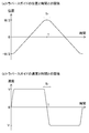
- FIG. 3A is a graph showing the relationship between the position of the traverse guide 33 in the traverse direction and time.
- FIG. 3B is a graph showing the relationship between speed and time in the traverse direction of the traverse guide 33.
- Information related to the traverse width is stored in the storage unit 19 (see FIG. 2) of the control device 13.
- the control device 13 controls the traverse motor 31 based on the information stored in the storage unit 19.
- the endless belt 32 is reciprocally driven, and the traverse guide 33 travels back and forth in the traverse direction.
- the horizontal axis represents time
- the vertical axis represents the position of the traverse guide 33 in the traverse direction.
- the left side of the center of the region (traverse region) where the traverse guide 33 reciprocates in the left-right direction is the positive direction of the vertical axis of the graph.
- the right side of the center of the traverse area is the negative direction of the vertical axis of the graph.
- the traverse guide 33 travels back and forth within the region of ⁇ W / 2 to W / 2 in the traverse direction. More specifically, for example, at a predetermined time (the left end of the graph in FIG. 3A), the traverse guide 33 is located at the right end (position of ⁇ W / 2). After a lapse of a predetermined time (denoted by T), the traverse guide 33 moves to the left end (W / 2 position). After that, the traverse guide 33 is reversed rightward and reaches the right end again. By repeating this, the traverse guide 33 travels back and forth.
- the horizontal axis represents time and the vertical axis represents the speed of the traverse guide 33 in the traverse direction.
- the controller 13 controls the traverse motor 31 to accelerate the traverse guide 33 to a predetermined speed (V). After that, the control device 13 maintains the speed of the traverse guide 33 constant until the traverse guide 33 reaches the vicinity of the left end (position of W / 2).
- the controller 13 controls the traverse motor 31 to perform the following reversal control.
- the control device 13 decelerates the traverse guide 33 traveling leftward (outward in the traverse direction) and reverses it rightward (inward in the traverse direction) at the position W / 2. After that, the control device 13 re-accelerates the traverse guide 33 to a predetermined speed (see -V in FIG. 3B).
- the time from the deceleration start of the traverse guide 33 to the re-acceleration completion in the reversal control is called the reversal time (Tr shown in FIGS. 3A and 3B).
- FIGS. 4A and 4B are explanatory diagrams of precision winding, and are diagrams in which the winding package Pw is developed in the rotation angle direction.
- the rotation angle at the upper end of the paper surface of the winding package Pw is 0 degrees
- the rotation angle at the lower end of the paper surface is 360 degrees.
- FIG. 4C is an explanatory diagram of creeping.
- Precision winding is a winding method that maintains a constant ratio (wind ratio) between the number of revolutions of the winding bobbin Bw and the number of reciprocating movements of the traverse guide 33 per unit time.
- wind ratio the ratio between the number of revolutions of the winding bobbin Bw and the number of reciprocating movements of the traverse guide 33 per unit time.
- the storage unit 19 stores, for example, information (table and calculation formula) regarding the relationship between the rotation angle of the winding bobbin Bw and the position of the traverse guide 33 in the traverse direction.
- the storage unit 19 stores the rotation angle of the winding bobbin Bw, and the acceleration / deceleration start position and the reversal position of the traverse guide 33 in the traverse direction in association with each other.
- the storage unit 19 stores a calculation formula for calculating the speed and / or the acceleration of the traverse guide 33 based on the information about the rotation angle of the winding bobbin Bw and the information about the position of the traverse guide 33. There is.
- the control device 13 controls the winding motor 22 and the traverse motor 31 based on the information stored in the storage unit 19.
- the control device 13 controls the winding motor 22 so as to maintain the rotation speed of the winding bobbin Bw constant.
- the take-up bobbin Bw makes 5 revolutions each time the traverse guide 33 makes one reciprocation. That is, as shown in FIG. 4A, each time the traverse guide 33 makes one reciprocation, the yarn Y is wound up by the amount of 5 rotations of the winding package Pw.
- the winding ratio is an integer as described above, there is a problem that the yarn Y is repeatedly wound on the same path on the surface of the winding package Pw (so-called ribbon winding occurs).
- the wind ratio is actually set to a value (for example, 5 + ⁇ ) slightly different from an integer, as shown in FIG. 4B.
- Creeping is to temporarily change the traverse width during the winding operation of the yarn Y for the purpose of suppressing the height of the winding package Pw.
- the ear height means that the amount of yarn wound around the axial end portion of the surface of the winding package Pw is larger than the amount of yarn wound around other portions because it is generally difficult to rapidly reverse the traverse guide 33. Will also increase.
- a step is likely to be formed on the surface of the winding package Pw, which may cause the yarn Y to traverse.
- it may cause deterioration of the shape of the winding package Pw and / or uneven density of the winding package Pw.
- the traverse device 23 is configured to reciprocally drive the endless belt 32 having the traverse guide 33 attached thereto by the traverse motor 31. Therefore, by controlling the traverse motor 31 with the control device 13, the reverse position of the traverse guide 33 can be arbitrarily changed.
- the control device 13 can switch the traverse width between a predetermined first width (Wa) and a second width (Wb) smaller than the first width, as shown in FIG. That is, creeping is possible).
- Wa predetermined first width
- Wb second width
- this distance is also referred to as a creeping amount.
- the control device 13 can change the creeping amount by controlling the traverse motor 31.
- the creeping amount is generally about 5 to 20 mm, but is not limited to this.
- the control device 13 can execute creeping at any timing. As an example, as shown in FIG. 4C, the control device 13 can execute creeping once every three reciprocations of the traverse guide 33.
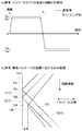
- FIG. 5A is a graph similar to FIG. 3B, showing the relationship between the speed of the traverse guide 33 and the time when the traverse width is simply narrowed during creeping (details will be described later).
- FIG. 5B is an explanatory diagram showing the path of the yarn Y on the surface of the winding package Pw when the traverse width is simply narrowed during creeping, and is an enlarged view of the left end portion of the winding package Pw.
- FIG. 6A is a graph similar to FIG.
- FIG. 6B is an explanatory diagram showing the path of the yarn Y on the surface of the winding package Pw when the traverse speed is simply reduced during creeping, and is an enlarged view of the left end portion of the winding package Pw. .
- the solid line indicates the traverse speed during normal operation
- the broken line indicates the traverse speed during creeping.
- the yarns Y1 and Y2 that are part of the yarn Y that is normally wound into the winding package Pw are inverted at points 101 and 102 on the end surface Pw1 of the winding package Pw, respectively.
- the yarn Y3, which is a part of the yarn Y wound up in the winding package Pw during creeping is inverted at the point 103 which is inside the points 101 and 102 by ⁇ W in the traverse direction.
- the point 103 is located closer to the front in the rotation angle direction than the reversal position (point 104) in the case where the traverse width when the yarn Y3 is wound is the same as the normal time.
- the yarn Y3 is wound in a state in which the yarn Y3 is largely displaced from the route 105 in which the yarn Y is wound when the creeping is not performed. Therefore, the shape of the surface of the winding package Pw is disturbed.
- the point 106 is in the same position as the point 104 described above in the rotation angle direction.
- the angle (the winding angle) formed by the yarn Y and the winding package Pw is deviated from each other between the normal time and the creeping time. That is, the yarns Y1 and Y2 that are a part of the yarn Y that is normally wound in the winding package Pw and the yarn Y3 that is a part of the yarn Y that is wound in the winding package Pw during creeping are parallel to each other. Disappear. Therefore, the shape of the surface of the winding package Pw is disturbed. Therefore, in the present embodiment, in order to suppress the fluctuation of the wind ratio even when creeping is performed during the execution of the precision winding, and to prevent the surface shape of the winding package Pw from being disturbed, the control device 13 is provided. The following control is performed.
- FIGS. 7 (a), (b), 8 (a), (b), 9 (a), and (b) For details of the yarn winding method using the above-described inversion control by the control device 13, FIGS. 7 (a), (b), 8 (a), (b), 9 (a), and (b) will be used. explain.
- FIG. 7A is a graph showing the relationship between the position of the traverse guide 33 in the traverse direction and time.
- FIG. 7B is a graph showing the relationship between speed and time in the traverse direction of the traverse guide 33.
- FIG. 8A is a graph showing the relationship between the acceleration of the traverse guide 33 in the traverse direction and time.
- FIG. 8B is a graph showing the relationship between the width of the reverse region and the creeping amount, which will be described later.
- FIGS. 7 (a), (b), 8 (a), (b), 9 (a), and (b) will be used. explain.
- FIG. 7A is a graph showing the relationship between the position of the traverse guide 33
- FIGS. 5B and 6B are explanatory views similar to FIGS. 5B and 6B, which show the paths of the yarn Y on the surface of the winding package Pw.
- the number of rotations of the winding package Pw is constant.
- the control device 13 performs the following control as the reversal control in the normal time (first reversal control).
- first inversion control the control device 13 inverts the traverse guide 33 at the first inversion position (Wa / 2 in FIG. 7A) in the traverse direction (first inversion step).
- first reversal control the time from the start of deceleration of the traverse guide 33 to the completion of reacceleration is defined as the first reversal time (Tra).
- the control device 13 performs the following control as the reversal control during creeping (second reversal control).
- the controller 13 reverses the traverse guide 33 at the second reversal position in the traverse direction (Wb / 2 in FIG. 7A) (second reversal step).
- the time from the start of deceleration of the traverse guide 33 to the completion of reacceleration is defined as the second reversal time (Trb).
- a region where the traverse guide 33 moves in the traverse direction from the start of deceleration to the completion of reacceleration is referred to as a reversal region.
- the width of the inversion region in the second inversion control is Wt, for example (see FIG. 7A).
- the controller 13 makes the second inversion time longer than the first inversion time (Trb> Tra), as shown in FIG. 7 (a). From another viewpoint, the control device 13 gently accelerates / decelerates the traverse guide 33 during the second inversion control as compared to during the first inversion control. More specifically, as compared with the maximum value of acceleration within the first inversion time during the first inversion control (Aa), the maximum value of acceleration within the second inversion time during the second inversion control (Ab) Yes) is made smaller (see FIG. 8A). In other words, the time average value of acceleration during the second reversal time during the second reversal control is made smaller than the time average value of acceleration during the first reversal control during the first reversal control.
- the control device 13 makes the traverse speed at the time other than the reversal control equal in the normal time and the creeping time (see FIG. 7B). Further, in the second reversal control, the control device 13 moves the traverse guide 33 to the second reversal position when half the second reversal time (Trb / 2) has elapsed since the deceleration of the traverse guide 33 was started.
- the traverse motor 31 is controlled so as to position.
- the yarn Y is wound into the winding package Pw as shown in FIG. 9 (a). That is, the portion of the yarn Y that is wound around the winding package Pw during creeping (the yarn Y3) is reversed at the point 107 in the traverse direction. The point 107 is at the same position as the point 104 described above in the rotation angle direction. Further, during the second inversion control (that is, when the traverse guide 33 is moving in the inversion region described above), the yarn Y3 is wound around the winding package Pw in an arc (see FIG. 9A). See hatched area 201).
- the traverse speeds other than during the reversal control are the same in the normal time and the creeping
- the traverse angles are the same in the normal time and the creeping except the reversal control.
- the yarn Y3 is wound along the above-described path 105 on the inner side of the region 201 in the traverse direction. That is, in this embodiment, the precision winding is normally performed, and the shape of the surface of the winding package Pw is prevented from being disturbed.
- the traverse guide 33 is located at the second reversal position when half the second reversal time (Trb / 2) has elapsed since the deceleration of the traverse guide 33 was started. Therefore, the inverted portion of the yarn Y3 has a symmetrical shape with the center axis of the winding package Pw as the center line. That is, the inverted portion of the yarn Y3 is formed cleanly.
- the controller 13 increases the width of the reversal region in the traverse direction as the creeping amount increases (see FIG. 8B). For example, when the creeping amount is ⁇ W1 larger than ⁇ W, the control device 13 sets the width of the inversion region to Wt1 wider than Wt (see FIGS. 9A and 9B). That is, when the second reversal time becomes long due to the narrowing of the traverse width during creeping, the region in which the traverse guide 33 can move in the traverse direction becomes wide during the second reversal control. Therefore, it is possible to prevent the traverse guide 33 from being continuously located in a narrow area in the traverse direction for a long time. Further, in this case, the arc drawn when the yarn Y3 is wound around the winding package Pw becomes large (see the area 202 in FIG. 9B).
- the second inversion time is longer than the first inversion time.
- the traveling speed of the traverse guide 33 can be made equal between the normal time and the creeping at timings other than the reversal. it can. Therefore, the angles of the yarn Y wound on the surface of the winding package Pw can be made uniform. Therefore, it is possible to prevent the surface shape of the winding package Pw from being disturbed.
- the larger the creeping amount the wider the reversal area. That is, when the second reversal time becomes long due to the narrowing of the traverse width during creeping, the movable area of the traverse guide 33 becomes large during the second reversal control. Therefore, it is possible to prevent the traverse guide 33 from being continuously located in a narrow area in the traverse direction for a long time. Therefore, it is possible to prevent the yarn Y from being intensively wound in a narrow area on the surface of the winding package Pw.
- the time from the start of deceleration of the traverse guide 33 until the traverse guide 33 reaches the second reversal position and the time from the departure of the traverse guide 33 from the second reversal position to the completion of the re-acceleration. can be equal.
- the shape of the inverted portion of the yarn Y can be made symmetrical with respect to the center axis of the winding package Pw (that is, the inverted portion can be formed neatly). Therefore, it is possible to prevent the shape of the inverted portion of the surface of the winding package Pw from being disturbed.
- control device 13 performs control based on information regarding the relationship between the rotation angle of the winding bobbin Bw and the position of the traverse guide 33.
- a complicated operation of performing creeping while maintaining a constant wind ratio can be facilitated.
- by rewriting the information it is possible to easily adjust the position and speed of the traverse guide 33 during the second reversal control.
- the traverse motor 31 is configured to be able to drive forward and reverse. This allows the traverse guide 33 to reciprocate by the forward and reverse driving of the traverse motor 31. Therefore, the reversing position and timing of the traverse guide 33 can be finely controlled by the control unit. Therefore, fine control of creeping can be easily performed.
- the traverse guide 33 can be easily linearly reciprocated by stretching the portion of the endless belt 32 to which the traverse guide 33 is attached and driving the same reciprocally. Therefore, it is possible to easily and regularly wind the yarn Y around the surface of the winding package Pw.
- the control device 13 is configured to gently accelerate and decelerate the traverse guide 33 during the second inversion control as compared with during the first inversion control, but the invention is not limited to this.
- the control device 13 sets the maximum value of the acceleration within the second reversal time during the second reversal control to the first acceleration during the first reversal control. It may be equal to the maximum value of the acceleration within the reversal time.
- the control device 13 may accelerate the traverse guide 33 again after stopping the traverse guide 33 at the second reversal position in the traverse direction for a predetermined time. In this way, the second inversion time may be set longer than the first inversion time.
- the control device 13 When the second reversal control in the above embodiment is A control and the second reversal control in the above modification examples (FIGS. 10A, 10B, and 11) is B control, the control device 13 is as follows. You may perform various controls. That is, the control device 13 may perform only the A control or only the B control as the second reversal control during the winding operation. Alternatively, the control device 13 may perform the A control and the B control in combination during the winding operation. More specifically, the control device 13 may repeatedly perform A control and B control as a second inversion control in a predetermined pattern. As an example of repetition, the control device 13 may alternately perform A control and B control.
- the larger the creeping amount the wider the width of the reversal region of the traverse guide 33 in the traverse direction, but the invention is not limited to this.
- the width of the reversal region may be constant regardless of the creeping amount.
- the control device 13 moves to the second reversal position when the half of the second reversal time has elapsed since the deceleration of the traverse guide 33 was started in the second reversal control.
- the traverse motor 31 is controlled so as to position the traverse guide 33.
- the control device 13 may perform control such that the traverse guide 33 is rapidly decelerated and then gently re-accelerated in the second reversal control.
- the control device 13 may perform control such that the traverse guide 33 is gently decelerated and then rapidly accelerated in the second reversal control.
- the storage unit 19 of the control device 13 stores both the table and the calculation formula as information regarding the relationship between the rotation angle of the winding bobbin Bw and the position of the traverse guide 33 in the traverse direction.
- the storage unit 19 may store only a calculation formula for calculating the position and / or speed of the traverse guide 33 based on the rotation angle of the winding bobbin Bw. That is, the control device 13 may always calculate the position and / or the speed of the traverse guide 33 based on the rotation angle of the winding bobbin Bw and the calculation formula during the winding operation.
- only the table may be stored in the storage unit 19 as information regarding the relationship between the rotation angle of the winding bobbin Bw and the position, speed, and acceleration of the traverse guide 33.
- the traverse guide 33 is attached to the endless belt 32, but the present invention is not limited to this.
- the traverse guide 33 may be attached to the tip end portion of the swing-driven arm (see Japanese Patent Laid-Open No. 2007-153554).
- the traverse guide 33 may be reciprocally driven by a linear motor or the like.
- the traverse guide 33 is driven by the drive source configured to be capable of forward and reverse driving, but the present invention is not limited to this.
- the rewinder 1 may include a cam type traverse device that uses a motor that is rotationally driven in one direction as a drive source.
- the number of rotations of the winding bobbin Bw is constant, but the number of rotations is not limited to this. That is, the control device 13 may control the winding motor 22 and the traverse motor 31 so as to keep the wind ratio constant in order to perform precision winding, and changes the rotation speed of the winding bobbin Bw during the winding operation. May be.
- the present invention is not limited to the rewinder 1 and can be applied to various yarn winding machines.
Abstract
The present invention suppresses fluctuations in winding ratio and prevents the surface shape of a package from being disturbed, even if creeping is performed during the execution of precision winding. The yarn winding machine comprises a guide driving unit that reciprocatingly drives a traverse guide and that can change the reversal position of the traverse guide during a yarn winding operation, and a control device. The control device can perform: a first reversing control wherein the traverse guide, which is traveling outward at a predetermined speed in the traversal direction, is decelerated, then reversed so as to travel inward at a first reversal position, and then re-accelerated to a predetermined speed; and a second reversing control wherein, the traverse guide, which is traveling outward at a predetermined speed in the traversal direction, is decelerated, then reversed so as to travel inward at a second reversal position further inward than the first reversal position, and then re-accelerated to a predetermined speed. The control device makes second reverse time (Trb) in the second reversing control longer than first reverse time (Tra) in the first reversing control during the execution of the precision winding.
Description
本発明は、糸巻取機、及び糸巻取方法に関する。
The present invention relates to a yarn winding machine and a yarn winding method.
特許文献1には、糸をトラバースガイドによってトラバースさせながらボビンに巻き取り、パッケージを形成する糸巻取機が開示されている。糸巻取機は、ボビンを回転駆動するボビン駆動用モータと、ガイド駆動用モータによってトラバースガイドを往復走行させるガイド駆動機構と、ボビン駆動用モータ及びガイド駆動用モータを制御する制御部とを備える。このような糸巻取機における糸の巻き方の一つに、ボビンの回転数と単位時間あたりのトラバース回数との比(ワインド比)を一定に制御する「プレシジョン巻」という巻き方がある。プレシジョン巻において、ワインド比は、一般的に、リボン巻が発生しないよう(パッケージ表面の同じ経路上に糸が繰り返し巻き取られないよう)、整数とわずかに異なる値に設定される。このようにすることで、プレシジョン巻では、リボン巻を回避するとともに、パッケージ表面における糸の巻取経路を少しずつずらしながら、糸を平行に規則正しく巻き取ることができる。これにより、形成されたパッケージからの糸の解舒性を向上させること、及び、パッケージの用途に応じてパッケージ密度をコントロールしやすくすることができる。
Patent Document 1 discloses a yarn winding machine that winds a yarn around a bobbin while traversing the yarn with a traverse guide to form a package. The yarn winding machine includes a bobbin driving motor that rotationally drives the bobbin, a guide driving mechanism that causes the traverse guide to travel back and forth by the guide driving motor, and a control unit that controls the bobbin driving motor and the guide driving motor. One of the winding methods of the yarn in such a yarn winding machine is a "precision winding" method in which the ratio (wind ratio) between the number of revolutions of the bobbin and the number of traverses per unit time is controlled to be constant. In precision winding, the wind ratio is generally set to a value that is slightly different from an integer so that ribbon winding does not occur (no repeated winding of the yarn on the same path on the package surface). By doing so, in the precision winding, the ribbon winding can be avoided, and the yarn can be regularly wound in parallel while shifting the winding route of the yarn on the package surface little by little. Thereby, the unwinding property of the yarn from the formed package can be improved, and the package density can be easily controlled according to the application of the package.
これとは別に、特許文献2には、パッケージの耳高を抑制するクリーピングを実施可能なトラバース装置が開示されている。耳高とは、トラバースガイドの急激な反転(方向転換)が一般的に難しいこと等に起因して、パッケージ表面の軸方向端部に巻かれる糸量が他の部分に巻かれる糸量よりも多くなることである。耳高は、パッケージ形状の悪化及び/又はパッケージ密度の不均一化等の原因となりうる。クリーピングとは、パッケージ形成中に、トラバースガイドの往復移動領域の幅(トラバース幅)を一時的に狭くすることである。これにより、クリーピングを行わない場合と比べて、パッケージの軸方向端部において巻き取られる糸量が少なくなり、耳高が緩和される。
Separately from this, Patent Document 2 discloses a traverse device capable of performing creeping for suppressing the height of the ear of the package. Ear height is because it is generally difficult to rapidly reverse (direction change) the traverse guide, and the amount of yarn wound around the axial end of the package surface is greater than the amount of yarn wound around other parts. It will be many. The ear height may cause deterioration of the package shape and / or non-uniformity of the package density. Creeping refers to temporarily narrowing the width of the reciprocating region of the traverse guide (traverse width) during package formation. As a result, as compared with the case where creeping is not performed, the amount of yarn wound around the axial end portion of the package is reduced, and the ear height is reduced.
特許文献1に記載の糸巻取機において、プレシジョン巻の最中にクリーピングを行おうとすると、以下の問題が発生しうる(なお、より詳細については、後述する実施形態において説明する)。まず、例えば、クリーピング時のトラバース幅を通常のトラバース時(以下、通常時)よりも単に狭くするだけでは、トラバース周期が変動してワインド比が一定に保たれなくなる。このため、パッケージ表面において、糸が実際に巻き取られる位置が、本来糸を巻き取りたい位置からずれてしまい、パッケージ表面の形状が乱れてしまう。したがって、これを防止するためには、トラバース周期を変動させずにクリーピングを行う必要がある。しかしながら、例えば、通常時とクリーピング時との間で単純にトラバースガイドの移動速度を異ならせることでワインド比の一定化を図ると、今度は糸とパッケージ表面とのなす角度(綾角)が通常時とクリーピング時との間で互いにずれてしまう。このため、やはりパッケージ表面の形状が乱れてしまう。
In the yarn winding machine described in Patent Document 1, the following problems may occur when trying to perform creeping during precision winding (more details will be described in an embodiment described later). First, for example, if the traverse width during creeping is simply made narrower than during normal traverse (hereinafter referred to as normal time), the traverse cycle changes and the wind ratio cannot be kept constant. For this reason, the position where the yarn is actually wound on the package surface is displaced from the position where the yarn is originally intended to be wound, and the shape of the package surface is disturbed. Therefore, in order to prevent this, it is necessary to perform creeping without changing the traverse cycle. However, for example, if the wind ratio is made constant by simply changing the moving speed of the traverse guide between the normal time and the creeping time, the angle formed by the yarn and the package surface (twist angle) will be changed. There is a shift between normal and creeping. Therefore, the shape of the package surface is also disturbed.
本発明の目的は、プレシジョン巻の実行中にクリーピングを行っても、ワインド比の変動を抑制し、且つ、パッケージ表面の形状が乱れることを抑制することである。
The object of the present invention is to suppress the fluctuation of the wind ratio and the disturbance of the shape of the package surface even if creeping is performed during the execution of precision winding.
第1の発明の糸巻取機は、走行中の糸をトラバースガイドによってトラバースさせながら回転中のボビンに巻取可能、且つ、前記ボビンの回転数と前記トラバースガイドの単位時間あたりの往復移動回数との比であるワインド比を一定に維持するプレシジョン巻を実行しつつパッケージを形成可能に構成された糸巻取機であって、前記トラバースガイドを所定のトラバース方向に往復駆動する、糸の巻取動作中に前記トラバースガイドの反転位置を変更可能なガイド駆動部と、制御部と、を備え、前記制御部は、前記ガイド駆動部を制御して、前記トラバース方向において、所定の速さで外側へ走行している前記トラバースガイドを減速させて所定の第1反転位置で内側へ反転させ、前記所定の速さまで再加速させる第1反転制御と、前記ガイド駆動部を制御して、前記トラバース方向において、前記所定の速さで外側へ走行している前記トラバースガイドを減速させて前記第1反転位置よりも内側にある第2反転位置で内側へ反転させ、前記所定の速さまで再加速させる第2反転制御と、を実行可能であり、前記プレシジョン巻の実行中に、前記第1反転制御における前記トラバースガイドの減速開始から再加速完了までの時間である第1反転時間よりも、前記第2反転制御における前記トラバースガイドの減速開始から再加速完了までの時間である第2反転時間を長くすることを特徴とするものである。
The yarn winding machine of the first invention is capable of winding a running yarn on a rotating bobbin while traversing the traveling traverse guide, and the number of revolutions of the bobbin and the number of reciprocating movements of the traverse guide per unit time. Is a yarn winding machine configured to form a package while performing a precision winding for maintaining a constant wind ratio, which is a yarn winding operation for reciprocally driving the traverse guide in a predetermined traverse direction. A guide driving unit capable of changing the reverse position of the traverse guide and a control unit are provided therein, and the control unit controls the guide driving unit to move outward at a predetermined speed in the traverse direction. A first reversal control for decelerating the traveling traverse guide to invert at a predetermined first reversal position, and reaccelerating to the predetermined speed; The idling drive unit is controlled to decelerate the traverse guide traveling outward at the predetermined speed in the traverse direction to invert at a second reversal position inside the first reversal position. The second reversal control for reaccelerating to the predetermined speed can be executed, and during the execution of the precision winding, the time from the deceleration start of the traverse guide to the reacceleration completion in the first reversal control can be performed. The second reversal time, which is the time from the start of deceleration of the traverse guide to the completion of reacceleration in the second reversal control, is made longer than a certain first reversal time.
クリーピングを行いつつプレシジョン巻を正常に行うための前提として、トラバースガイドが第1反転位置で反転する場合(以下、通常時とも呼ぶ)と第2反転位置で反転する場合(以下、クリーピング時とも呼ぶ)とで、ワインド比を等しくする必要がある。ワインド比を等しくするためには、例えばボビンの回転数を一定としたとき、通常時よりもトラバースガイドの移動領域の幅が狭いクリーピング時においても、トラバースガイドの移動周期を通常時と等しくする必要がある。
As a premise for normally performing precision winding while performing creeping, the traverse guide is reversed at the first reverse position (hereinafter also referred to as normal time) and at the second reverse position (hereinafter, during creeping). Also called), it is necessary to make the wind ratio equal. In order to equalize the wind ratio, for example, when the bobbin rotation speed is constant, the traverse guide movement period is set to be equal to the normal time even during creeping when the width of the traverse guide movement area is narrower than in the normal time. There is a need.
本発明では、第2反転時間が第1反転時間よりも長い。このように、クリーピング時の反転時間を積極的に長くすることにより、クリーピング時のトラバースガイドの移動周期を長くすることができる。これにより、通常時とクリーピング時とでトラバースガイドの移動周期を等しくすることができる。したがって、ワインド比の変動を防止できる。
In the present invention, the second inversion time is longer than the first inversion time. Thus, by positively prolonging the reversal time during creeping, it is possible to prolong the movement cycle of the traverse guide during creeping. This makes it possible to equalize the movement cycle of the traverse guide between the normal time and the creeping time. Therefore, it is possible to prevent the fluctuation of the wind ratio.
さらに、このように、第2反転時間の調整によってクリーピング時のトラバース周期を調整できるので、反転時以外のタイミングにおいては、トラバースガイドの走行速度を通常時とクリーピング時とで等しくすることができる。このため、パッケージ表面に巻き取られる糸の角度を揃えることができる。したがって、パッケージ表面の形状が乱れることを抑制できる。
Further, since the traverse cycle at the time of creeping can be adjusted by adjusting the second reversal time in this manner, the traveling speed of the traverse guide can be made equal between the normal time and the creeping at timings other than the reversal timing. it can. Therefore, the angles of the yarn wound around the package surface can be made uniform. Therefore, it is possible to prevent the shape of the package surface from being disturbed.
以上のようにして、プレシジョン巻の実行中にクリーピングを行っても、ワインド比の変動を抑制でき、且つ、パッケージ表面の形状が乱れることを抑制できる。
As described above, even if creeping is performed during the execution of precision winding, it is possible to suppress the fluctuation of the wind ratio and prevent the shape of the package surface from being disturbed.
第2の発明の糸巻取機は、前記第1の発明において、前記制御部は、前記トラバース方向における前記第1反転位置と前記第2反転位置との距離が長いほど、前記第2反転制御において、前記第2反転時間内に前記トラバースガイドが前記トラバース方向に移動する領域の幅を広くすることを特徴とするものである。
In the yarn winding machine of the second invention, in the first invention, in the second inversion control, the control unit has a longer distance between the first inversion position and the second inversion position in the traverse direction. The width of the region in which the traverse guide moves in the traverse direction is widened within the second inversion time.
ワインド比の変動を抑制しつつパッケージ表面の形状乱れを抑制するためには、第1反転位置と第2反転位置との距離が長いほど(すなわち、クリーピング時のトラバース幅が狭いほど)、第2反転時間を長くする必要がある。ここで、第2反転時間内にトラバース方向においてトラバースガイドが移動する領域(以下、反転領域とする)の幅が一定である場合、第2反転時間が長くなると、トラバースガイドは、第2反転制御時に第2反転位置の近傍の領域に長時間位置し続けることとなる。すると、パッケージ表面の狭い領域に糸が集中的に巻き取られやすくなる。その結果、パッケージ表面に段差ができやすくなり、糸の綾落ちが発生する等、パッケージの形状等に悪影響が生じるおそれがある。
In order to suppress the disturbance of the shape of the package surface while suppressing the fluctuation of the wind ratio, the longer the distance between the first reversal position and the second reversal position (that is, the narrower the traverse width during creeping) is, 2 It is necessary to lengthen the reversal time. Here, when the width of the region in which the traverse guide moves in the traverse direction within the second reversal time (hereinafter referred to as the reversal region) is constant, if the second reversal time becomes long, the traverse guide causes the second reversal control. Occasionally, it will remain in the area near the second reversal position for a long time. Then, the yarn is likely to be intensively wound around the narrow area on the surface of the package. As a result, the surface of the package is likely to have a step, and the yarn may fall off, which may adversely affect the shape of the package.
本発明では、第1反転位置と第2反転位置との距離が長いほど、反転領域の幅が広い。つまり、クリーピング時のトラバース幅が狭くなることによって第2反転時間が長くなった場合、第2反転制御中にトラバースガイドが移動可能な領域が広くなる。このため、トラバース方向における狭い領域内にトラバースガイドが長時間位置し続けることを抑制できる。したがって、パッケージ表面の狭い領域に糸が集中的に巻き取られることを抑制できる。
In the present invention, the longer the distance between the first reversal position and the second reversal position, the wider the reversal region. That is, when the second reversal time becomes long due to the narrowing of the traverse width during creeping, the region where the traverse guide can move during the second reversal control becomes wider. Therefore, it is possible to prevent the traverse guide from being continuously positioned for a long time within a narrow area in the traverse direction. Therefore, it is possible to prevent the yarn from being intensively wound in a narrow area on the surface of the package.
第3の発明の糸巻取機は、前記第1又は第2の発明において、前記制御部は、前記第2反転制御において、前記トラバースガイドの減速を開始させてから前記第2反転時間の半分の時間が経過したときに前記トラバース方向における前記第2反転位置に前記トラバースガイドを位置させるように、前記ガイド駆動部を制御することを特徴とするものである。
In the yarn winding machine according to a third aspect of the present invention, in the first or second aspect of the invention, in the second reversal control, the control unit starts deceleration of the traverse guide for half the second reversal time. The guide drive unit is controlled so that the traverse guide is positioned at the second reversal position in the traverse direction when time passes.
第2反転制御において、例えば、トラバースガイドを急減速させて第2反転位置に到達させ、その後緩やかに再加速させることも可能である。但し、この場合、パッケージ表面に巻き取られる糸の反転部分の形状が、トラバースガイドの減速時と再加速時とで大きく異なるおそれがある。このため、パッケージ表面の糸の反転部分の形状が非対称となり、反転部分をきれいに形成できないおそれがある。本発明では、トラバースガイドの減速を開始させてからトラバースガイドが第2反転位置に到達するまでの時間と、トラバースガイドが第2反転位置を離れてから再加速が完了するまでの時間とを等しくすることができる。これにより、糸の反転部分の形状を、パッケージの中心軸を中心線とした対称形状とすることができる(つまり、反転部分をきれいに形成することができる)。したがって、パッケージ表面の反転部分の形状が乱れることを抑制できる。
In the second reversal control, for example, the traverse guide can be rapidly decelerated to reach the second reversal position, and then gradually re-accelerated. However, in this case, the shape of the inverted portion of the yarn wound around the package surface may be significantly different between when the traverse guide is decelerated and when it is re-accelerated. For this reason, the shape of the reverse portion of the yarn on the package surface becomes asymmetric, and the reverse portion may not be formed cleanly. In the present invention, the time from the start of deceleration of the traverse guide until the traverse guide reaches the second inversion position is equal to the time from the departure of the traverse guide from the second inversion position to the completion of reacceleration. can do. As a result, the shape of the inverted portion of the yarn can be made symmetrical with respect to the center axis of the package (that is, the inverted portion can be formed neatly). Therefore, it is possible to suppress the disorder of the shape of the inverted portion of the package surface.
第4の発明の糸巻取機は、前記第1~第3のいずれかの発明において、前記ボビンを回転駆動するボビン駆動部を備え、前記制御部は、前記ボビンの回転角度と前記トラバースガイドの前記トラバース方向における位置との関係に関する情報を記憶する記憶部を有し、前記記憶部に記憶されている前記情報に基づいて前記ボビン駆動部及び前記ガイド駆動部を制御することを特徴とするものである。
The yarn winding machine of a fourth invention is the yarn winding machine of any one of the first to third inventions, further comprising a bobbin drive unit that rotationally drives the bobbin, and the control unit controls the rotation angle of the bobbin and the traverse guide. A storage unit that stores information about a relationship with a position in the traverse direction, and controls the bobbin drive unit and the guide drive unit based on the information stored in the storage unit. Is.
本発明では、ボビンの回転角度とトラバースガイドの位置との関係に関する情報に基づく制御を行うことにより、例えば複雑な機械構造を用いた制御を行う場合と比べて、ワインド比を一定に維持しつつクリーピングも行うという複雑な動作を容易化できる。また、当該情報を書き換えることで、第2反転制御時のトラバースガイドの位置及び/又は速度等の調整を容易に行うことができる。
In the present invention, by performing control based on information regarding the relationship between the rotation angle of the bobbin and the position of the traverse guide, while maintaining a constant wind ratio, as compared with the case of performing control using a complicated mechanical structure, for example. The complicated operation of creeping can be facilitated. Further, by rewriting the information, it is possible to easily adjust the position and / or speed of the traverse guide during the second inversion control.
第5の発明の糸巻取機は、前記第1~第4のいずれかの発明において、前記ガイド駆動部は、正逆駆動可能に構成された駆動源を有することを特徴とするものである。
The yarn winding machine of the fifth invention is characterized in that, in any one of the first to fourth inventions, the guide drive unit has a drive source configured to be capable of forward and reverse drive.
例えば、一般的なカム式のトラバース装置では、一方向に回転するモータが駆動源として用いられており、且つ、クリーピングを行うための構造が複雑な機械構造となっている。このため、カム式のトラバース装置では、クリーピングの細かい制御が困難である。本発明では、駆動源の正逆駆動によってトラバースガイドに往復走行を行わせることができる。このため、トラバースガイドの反転の位置及びタイミング等を制御部によって細かく制御できる。したがって、クリーピングの細かい制御を容易に行うことができる。
For example, in a general cam type traverse device, a motor that rotates in one direction is used as a drive source, and the structure for performing creeping is a complicated mechanical structure. For this reason, it is difficult for the cam type traverse device to perform fine control of creeping. In the present invention, the traverse guide can be made to travel back and forth by the forward and reverse drive of the drive source. Therefore, the position and timing of reversal of the traverse guide can be finely controlled by the control unit. Therefore, fine control of creeping can be easily performed.
第6の発明の糸巻取機は、前記第5の発明において、前記ガイド駆動部は、前記トラバースガイドが取り付けられ、前記駆動源によって往復駆動されるベルト部材を有することを特徴とするものである。
A yarn winding machine according to a sixth aspect of the present invention is characterized in that, in the fifth aspect, the guide drive unit includes a belt member to which the traverse guide is attached and which is reciprocally driven by the drive source. .
例えば揺動可能なアームの先端部にトラバースガイドが取り付けられ、アームが揺動駆動される構成では、トラバースガイドが弧を描くように往復走行する。このため、プレシジョン巻を行っても、パッケージ表面に糸を規則正しく巻き取ることが難しいおそれがある。本発明では、ベルト部材のトラバースガイドが取り付けられた部分を直線状に張って往復駆動することにより、トラバースガイドを容易に直線的に往復走行させることができる。したがって、パッケージ表面に糸を規則正しく巻き取りやすくすることができる。
For example, in a configuration in which a traverse guide is attached to the tip of a swingable arm and the arm is driven to swing, the traverse guide travels back and forth in an arc. Therefore, even if precision winding is performed, it may be difficult to regularly wind the yarn around the package surface. In the present invention, the portion of the belt member to which the traverse guide is attached is stretched linearly and is reciprocally driven, so that the traverse guide can be easily linearly reciprocated. Therefore, it is possible to easily and regularly wind the yarn around the package surface.
第7の発明の糸巻取方法は、走行中の糸をトラバースガイドによってトラバースさせながら回転中のボビンに巻き取り、前記ボビンの回転数と前記トラバースガイドの単位時間あたりの往復移動回数との比であるワインド比を一定に維持するプレシジョン巻を実行しつつパッケージを形成する糸巻取方法であって、所定のトラバース方向において、所定の速さで外側へ走行している前記トラバースガイドを減速させて所定の第1反転位置で内側へ反転させ、前記所定の速さまで再加速させる第1反転工程と、前記トラバース方向において、前記所定の速さで外側へ走行している前記トラバースガイドを減速させて前記第1反転位置よりも内側にある第2反転位置で内側へ反転させ、前記所定の速さまで再加速させる第2反転工程と、を実行し、前記プレシジョン巻の実行中に、前記第1反転工程における前記トラバースガイドの減速開始から再加速完了までの時間である第1反転時間よりも、前記第2反転工程における前記トラバースガイドの減速開始から再加速完了までの時間である第2反転時間を長くすることを特徴とするものである。
In the yarn winding method of the seventh invention, the running yarn is wound around a rotating bobbin while being traversed by a traverse guide, and the ratio of the number of revolutions of the bobbin to the number of reciprocating movements of the traverse guide per unit time is calculated. A yarn winding method for forming a package while performing precision winding for maintaining a certain wind ratio constant, by decelerating the traverse guide running outward at a predetermined speed in a predetermined traverse direction A first reversing step of reversing inward at the first reversing position and re-accelerating to the predetermined speed, and decelerating the traverse guide traveling outward at the predetermined speed in the traverse direction, A second reversing step of reversing inward at a second reversing position inside the first reversing position and re-accelerating to the predetermined speed. During the execution of the precision winding, from the deceleration start of the traverse guide in the second reversing step to the first reversal time which is the time from the deceleration start of the traverse guide to the re-acceleration completion in the first reversing step. The second reversal time, which is the time until the completion of reacceleration, is lengthened.
本発明では、第1の発明と同様に、プレシジョン巻の実行中にクリーピングを行っても、ワインド比の変動を抑制でき、且つ、パッケージ表面の形状が乱れることを抑制できる。
Like the first invention, in the present invention, even if creeping is performed during the execution of precision winding, it is possible to suppress the fluctuation of the wind ratio and to prevent the shape of the package surface from being disturbed.
次に、本発明の実施形態について、図1~図9を参照しながら説明する。図1に示す上下方向及び左右方向を、それぞれリワインダ1の上下方向及び左右方向とする。上下方向及び左右方向の両方と直交する方向(図1の紙面垂直方向)を、前後方向とする。糸Yの走行する方向を糸走行方向とする。
Next, an embodiment of the present invention will be described with reference to FIGS. 1 to 9. The vertical direction and the horizontal direction shown in FIG. 1 are the vertical direction and the horizontal direction of the rewinder 1, respectively. The direction orthogonal to both the up-down direction and the left-right direction (the direction perpendicular to the paper surface of FIG. 1) is the front-back direction. The traveling direction of the yarn Y is referred to as a yarn traveling direction.
(リワインダの構成)
まず、図1を用いて、本実施形態に係るリワインダ1(本発明の糸巻取機)の構成について説明する。図1は、リワインダ1を正面から見た模式図である。図1に示すように、リワインダ1は、給糸部11と、巻取部12と、制御装置13(本発明の制御部)等を備える。リワインダ1は、給糸部11に支持されている給糸パッケージPsから糸Yを解舒して、巻取部12によって巻取ボビンBw(本発明のボビン)に巻き返し、巻取パッケージPw(本発明のパッケージ)を形成するためのものである。より具体的には、リワインダ1は、例えば給糸パッケージPsに巻かれている糸Yをよりきれいに巻き直したり、所望の密度の巻取パッケージPwを形成したりするためのものである。 (Rewinder configuration)
First, the configuration of the rewinder 1 (yarn winding machine of the present invention) according to the present embodiment will be described with reference to FIG. FIG. 1 is a schematic view of the rewinder 1 viewed from the front. As shown in FIG. 1, the rewinder 1 includes ayarn supplying unit 11, a winding unit 12, a control device 13 (control unit of the present invention), and the like. The rewinder 1 unwinds the yarn Y from the yarn supplying package Ps supported by the yarn supplying unit 11, rewinds the yarn Y onto the winding bobbin Bw (bobbin of the present invention) by the winding unit 12, and the winding package Pw (book). The invention package). More specifically, the rewinder 1 is, for example, for rewinding the yarn Y wound around the yarn supplying package Ps more neatly, or forming a winding package Pw having a desired density.
まず、図1を用いて、本実施形態に係るリワインダ1(本発明の糸巻取機)の構成について説明する。図1は、リワインダ1を正面から見た模式図である。図1に示すように、リワインダ1は、給糸部11と、巻取部12と、制御装置13(本発明の制御部)等を備える。リワインダ1は、給糸部11に支持されている給糸パッケージPsから糸Yを解舒して、巻取部12によって巻取ボビンBw(本発明のボビン)に巻き返し、巻取パッケージPw(本発明のパッケージ)を形成するためのものである。より具体的には、リワインダ1は、例えば給糸パッケージPsに巻かれている糸Yをよりきれいに巻き直したり、所望の密度の巻取パッケージPwを形成したりするためのものである。 (Rewinder configuration)
First, the configuration of the rewinder 1 (yarn winding machine of the present invention) according to the present embodiment will be described with reference to FIG. FIG. 1 is a schematic view of the rewinder 1 viewed from the front. As shown in FIG. 1, the rewinder 1 includes a
給糸部11は、例えば、立設された機台14の下部の前面に取り付けられている。給糸部11は、給糸ボビンBsに糸Yが巻かれて形成された給糸パッケージPsを支持するように構成されている。これにより、給糸部11は、糸Yを供給可能となっている。
The yarn feeder 11 is attached to the front surface of the lower part of the machine stand 14 that is erected, for example. The yarn supplying unit 11 is configured to support a yarn supplying package Ps formed by winding a yarn Y on a yarn supplying bobbin Bs. Thereby, the yarn supplying section 11 can supply the yarn Y.
巻取部12は、巻取ボビンBwに糸Yを巻き取って巻取パッケージPwを形成するためのものである。巻取部12は、機台14の上部に設けられている。巻取部12は、クレードルアーム21と、巻取モータ22(本発明のボビン駆動部)と、トラバース装置23と、コンタクトローラ24等を有する。
The winding unit 12 is for winding the yarn Y on the winding bobbin Bw to form a winding package Pw. The winding unit 12 is provided on the upper portion of the machine base 14. The winding unit 12 includes a cradle arm 21, a winding motor 22 (bobbin driving unit of the present invention), a traverse device 23, a contact roller 24, and the like.
クレードルアーム21は、例えば、機台14に揺動可能に支持されている。クレードルアーム21は、例えば左右方向を巻取ボビンBwの軸方向として、巻取ボビンBwを回転可能に支持する。クレードルアーム21の先端部には、巻取ボビンBwを把持するボビンホルダ(不図示)が回転可能に取り付けられている。巻取モータ22は、ボビンホルダを回転駆動するためのものである。巻取モータ22は、例えば一般的な交流モータであり、回転数を変更可能に構成されている。これにより、巻取モータ22は、巻取ボビンBwの回転速度を変更可能となっている。巻取モータ22は、制御装置13と電気的に接続されている(図2参照)。
The cradle arm 21 is swingably supported by the machine base 14, for example. The cradle arm 21 rotatably supports the take-up bobbin Bw with the left-right direction as the axial direction of the take-up bobbin Bw. A bobbin holder (not shown) that holds the take-up bobbin Bw is rotatably attached to the tip of the cradle arm 21. The winding motor 22 is for rotating and driving the bobbin holder. The winding motor 22 is, for example, a general AC motor, and is configured to be able to change the rotation speed. Accordingly, the winding motor 22 can change the rotation speed of the winding bobbin Bw. The winding motor 22 is electrically connected to the control device 13 (see FIG. 2).
トラバース装置23は、巻取ボビンBwの軸方向(本実施形態では左右方向)に糸Yをトラバースさせる装置である。トラバース装置23は、巻取パッケージPwの糸走行方向におけるすぐ上流側に配置されている。トラバース装置23は、トラバースモータ31(本発明のガイド駆動部)と、無端ベルト32(本発明のベルト部材)と、トラバースガイド33とを有する。
The traverse device 23 is a device for traversing the yarn Y in the axial direction of the winding bobbin Bw (in the present embodiment, the left-right direction). The traverse device 23 is arranged immediately upstream of the winding package Pw in the yarn traveling direction. The traverse device 23 includes a traverse motor 31 (guide drive unit of the present invention), an endless belt 32 (belt member of the present invention), and a traverse guide 33.
トラバースモータ31は、例えば一般的な交流モータである。トラバースモータ31は、正転駆動及び逆転駆動可能に構成され、且つ、回転数を変更可能に構成された駆動源である。トラバースモータ31は、制御装置13と電気的に接続されている(図2参照)。無端ベルト32は、トラバースガイド33が取り付けられたベルト部材である。無端ベルト32は、左右方向に互いに離間して配置されたプーリ34及びプーリ35と、トラバースモータ31の回転軸に連結された駆動プーリ36とに巻き掛けられており、略三角形状に張られている。無端ベルト32は、トラバースモータ31によって往復駆動される。トラバースガイド33は、無端ベルト32に取り付けられ、左右方向においてプーリ34とプーリ35の間に配置されている。トラバースガイド33は、無端ベルト32がトラバースモータ31によって往復駆動されることにより、左右方向に直線的に往復走行させられる(図1の矢印参照)。これにより、トラバースガイド33は、糸Yを左右方向にトラバースさせる。以下では、左右方向をトラバース方向とも呼ぶ。上記のような構成を有するトラバース装置23では、トラバースモータ31の回転軸の回転方向の切換タイミング等を制御することにより、糸Yの巻取動作中にトラバースガイド33の移動領域の幅(トラバース幅)を変更可能となっている。
The traverse motor 31 is, for example, a general AC motor. The traverse motor 31 is a drive source that is configured to be capable of normal rotation driving and reverse rotation driving and that is capable of changing the number of rotations. The traverse motor 31 is electrically connected to the control device 13 (see FIG. 2). The endless belt 32 is a belt member to which the traverse guide 33 is attached. The endless belt 32 is wound around a pulley 34 and a pulley 35 that are spaced apart from each other in the left-right direction and a drive pulley 36 that is connected to the rotation shaft of the traverse motor 31, and is stretched in a substantially triangular shape. There is. The endless belt 32 is reciprocally driven by the traverse motor 31. The traverse guide 33 is attached to the endless belt 32, and is arranged between the pulleys 34 and 35 in the left-right direction. The traverse guide 33 is linearly reciprocated in the left-right direction when the endless belt 32 is reciprocally driven by the traverse motor 31 (see the arrow in FIG. 1). As a result, the traverse guide 33 traverses the yarn Y in the left-right direction. Below, the left-right direction is also referred to as the traverse direction. In the traverse device 23 having the above-described configuration, the width of the moving region of the traverse guide 33 (traverse width) during the winding operation of the yarn Y is controlled by controlling the switching timing of the rotation direction of the rotation shaft of the traverse motor 31. ) Can be changed.
コンタクトローラ24は、巻取パッケージPwの表面に接圧を付与して巻取パッケージPwの形状を整えるためのものである。コンタクトローラ24は、巻取パッケージPwに接触し、巻取パッケージPwの回転に従動して回転する。
The contact roller 24 is for applying a contact pressure to the surface of the winding package Pw to adjust the shape of the winding package Pw. The contact roller 24 contacts the winding package Pw and rotates following the rotation of the winding package Pw.
糸走行方向において、給糸部11と巻取部12との間には、上流側から順に糸ガイド15、案内ローラ16、テンションセンサ17が配置されている。糸ガイド15は、例えば給糸ボビンBsの中心軸の延長線上に配置されており、給糸パッケージPsから解舒された糸Yを糸走行方向下流側へ案内する。案内ローラ16は、糸ガイド15によって案内された糸Yをさらに糸走行方向下流側へ案内するためのものである。案内ローラ16は、機台14の前面且つ糸ガイド15の上方に配置されている。案内ローラ16は、例えばローラ駆動モータ18によって回転駆動される。ローラ駆動モータ18は、例えば一般的な交流モータであり、回転数を変更可能に構成されている。これにより、ローラ駆動モータ18は、案内ローラ16の回転速度を変更可能となっている。ローラ駆動モータ18は、制御装置13と電気的に接続されている(図2参照)。本実施形態では、案内ローラ16の周速度と巻取パッケージPwの周速度との速度差によって、糸Yにテンションが付与される。
A yarn guide 15, a guide roller 16, and a tension sensor 17 are arranged in this order from the upstream side between the yarn supplying section 11 and the winding section 12 in the yarn traveling direction. The yarn guide 15 is arranged, for example, on an extension line of the central axis of the yarn supplying bobbin Bs, and guides the yarn Y unwound from the yarn supplying package Ps to the downstream side in the yarn traveling direction. The guide roller 16 is for guiding the yarn Y guided by the yarn guide 15 further downstream in the yarn traveling direction. The guide roller 16 is arranged on the front surface of the machine base 14 and above the thread guide 15. The guide roller 16 is rotationally driven by, for example, a roller drive motor 18. The roller drive motor 18 is, for example, a general AC motor, and is configured to be able to change the rotation speed. Thereby, the roller drive motor 18 can change the rotation speed of the guide roller 16. The roller drive motor 18 is electrically connected to the control device 13 (see FIG. 2). In the present embodiment, tension is applied to the yarn Y by the speed difference between the peripheral speed of the guide roller 16 and the peripheral speed of the winding package Pw.
テンションセンサ17は、糸走行方向において巻取パッケージPwと案内ローラ16との間に配置されており、糸Yに付与されているテンションを検知する。テンションセンサ17は、制御装置13と電気的に接続されており(図2参照)、テンションの検知結果を制御装置13に送る。
The tension sensor 17 is arranged between the winding package Pw and the guide roller 16 in the yarn traveling direction, and detects the tension applied to the yarn Y. The tension sensor 17 is electrically connected to the control device 13 (see FIG. 2) and sends the tension detection result to the control device 13.
制御装置13は、CPUと、ROMと、RAM(記憶部19)等を備える。記憶部19には、例えば、糸Yの巻取量や巻取速度、糸Yに付与するテンションの強さ等のパラメータが記憶されている。制御装置13は、RAM(記憶部19)に記憶されたパラメータ等に基づいて、ROMに格納されたプログラム従い、CPUにより各部を制御する。
The control device 13 includes a CPU, a ROM, a RAM (storage unit 19), and the like. The storage unit 19 stores parameters such as the winding amount and winding speed of the yarn Y and the strength of the tension applied to the yarn Y. The control device 13 controls each unit by the CPU according to the program stored in the ROM based on the parameters stored in the RAM (storage unit 19).
以上のようなリワインダ1において、給糸パッケージPsから解舒された糸Yが糸走行方向における下流側へ走行する。走行中の糸Yは、トラバースガイド33によって左右方向(トラバース方向)にトラバースされながら、回転中の巻取ボビンBwに巻き取られる(糸の巻取動作)。
In the rewinder 1 as described above, the yarn Y unwound from the yarn supply package Ps runs downstream in the yarn running direction. The traveling yarn Y is wound around the rotating winding bobbin Bw while being traversed in the left-right direction (traverse direction) by the traverse guide 33 (a yarn winding operation).
(トラバースガイドの移動制御)
次に、制御装置13によるトラバースガイド33の基本的な移動制御について、図3を用いて説明する。図3(a)は、トラバースガイド33のトラバース方向における位置と時間との関係を示すグラフである。図3(b)は、トラバースガイド33のトラバース方向における速度と時間との関係を示すグラフである。 (Movement control of traverse guide)
Next, basic movement control of thetraverse guide 33 by the control device 13 will be described with reference to FIG. FIG. 3A is a graph showing the relationship between the position of the traverse guide 33 in the traverse direction and time. FIG. 3B is a graph showing the relationship between speed and time in the traverse direction of the traverse guide 33.
次に、制御装置13によるトラバースガイド33の基本的な移動制御について、図3を用いて説明する。図3(a)は、トラバースガイド33のトラバース方向における位置と時間との関係を示すグラフである。図3(b)は、トラバースガイド33のトラバース方向における速度と時間との関係を示すグラフである。 (Movement control of traverse guide)
Next, basic movement control of the
制御装置13の記憶部19(図2参照)には、トラバース幅に関する情報が記憶されている。制御装置13は、記憶部19に記憶された情報に基づいてトラバースモータ31を制御する。これにより、無端ベルト32が往復駆動され、トラバースガイド33がトラバース方向に往復走行する。
Information related to the traverse width is stored in the storage unit 19 (see FIG. 2) of the control device 13. The control device 13 controls the traverse motor 31 based on the information stored in the storage unit 19. As a result, the endless belt 32 is reciprocally driven, and the traverse guide 33 travels back and forth in the traverse direction.
図3(a)に示すグラフにおいて、横軸は時間を示しており、縦軸はトラバースガイド33のトラバース方向における位置を示している。説明の便宜上、左右方向において、トラバースガイド33が往復移動する領域(トラバース領域)の中心よりも左方をグラフの縦軸の正方向とする。また、トラバース領域の中心よりも右方をグラフの縦軸の負方向とする。
In the graph shown in FIG. 3A, the horizontal axis represents time, and the vertical axis represents the position of the traverse guide 33 in the traverse direction. For convenience of explanation, the left side of the center of the region (traverse region) where the traverse guide 33 reciprocates in the left-right direction is the positive direction of the vertical axis of the graph. The right side of the center of the traverse area is the negative direction of the vertical axis of the graph.
一例として、トラバース幅をWとしたとき、図3(a)に示すように、トラバースガイド33は、トラバース方向において-W/2~W/2の領域内を往復走行する。より具体的には、例えば、所定時刻(図3(a)のグラフの左端)において、トラバースガイド33が右端(-W/2の位置)に位置している。所定時間(Tとする)経過後に、トラバースガイド33は左端(W/2の位置)まで移動する。その後、トラバースガイド33は、右方に反転し、再び右端に到達する。これを繰り返すことにより、トラバースガイド33が往復走行する。
As an example, when the traverse width is W, as shown in FIG. 3 (a), the traverse guide 33 travels back and forth within the region of −W / 2 to W / 2 in the traverse direction. More specifically, for example, at a predetermined time (the left end of the graph in FIG. 3A), the traverse guide 33 is located at the right end (position of −W / 2). After a lapse of a predetermined time (denoted by T), the traverse guide 33 moves to the left end (W / 2 position). After that, the traverse guide 33 is reversed rightward and reaches the right end again. By repeating this, the traverse guide 33 travels back and forth.
図3(b)に示すグラフにおいて、横軸は時間を示しており、縦軸はトラバースガイド33のトラバース方向における速度を示している。以下、具体例について説明する。トラバースガイド33が右端(-W/2の位置)に位置しているとき、トラバースガイド33の速度はゼロである。制御装置13は、トラバースモータ31を制御して、トラバースガイド33を所定の速さ(Vとする)まで加速させる。その後、制御装置13は、トラバースガイド33が左端(W/2の位置)近傍に到達するまでトラバースガイド33の速度を一定に維持する。トラバースガイド33が左端近傍に到達したとき、制御装置13はトラバースモータ31を制御して、以下のような反転制御を行う。すなわち、制御装置13は、左方(トラバース方向における外側)へ走行しているトラバースガイド33を減速させてW/2の位置で右方(トラバース方向における内側)へ反転させる。その後、制御装置13は、トラバースガイド33を所定の速さまで再加速させる(図3(b)の-Vを参照)。本実施形態では、反転制御におけるトラバースガイド33の減速開始から再加速完了までの時間を、反転時間(図3(a)、(b)に示すTr)と呼ぶ。
In the graph shown in FIG. 3 (b), the horizontal axis represents time and the vertical axis represents the speed of the traverse guide 33 in the traverse direction. Hereinafter, a specific example will be described. When the traverse guide 33 is located at the right end (position of -W / 2), the speed of the traverse guide 33 is zero. The controller 13 controls the traverse motor 31 to accelerate the traverse guide 33 to a predetermined speed (V). After that, the control device 13 maintains the speed of the traverse guide 33 constant until the traverse guide 33 reaches the vicinity of the left end (position of W / 2). When the traverse guide 33 reaches the vicinity of the left end, the controller 13 controls the traverse motor 31 to perform the following reversal control. That is, the control device 13 decelerates the traverse guide 33 traveling leftward (outward in the traverse direction) and reverses it rightward (inward in the traverse direction) at the position W / 2. After that, the control device 13 re-accelerates the traverse guide 33 to a predetermined speed (see -V in FIG. 3B). In the present embodiment, the time from the deceleration start of the traverse guide 33 to the re-acceleration completion in the reversal control is called the reversal time (Tr shown in FIGS. 3A and 3B).
(プレシジョン巻及びクリーピング)
次に、プレシジョン巻及びクリーピングについて、図4(a)~(c)を用いて説明する。図4(a)、(b)は、プレシジョン巻の説明図であり、巻取パッケージPwを回転角度方向に展開した図である。説明の便宜上、図4(a)、(b)に示すように、巻取パッケージPwの紙面上端における回転角度を0度とし、紙面下端における回転角度を360度とする。図4(c)は、クリーピングの説明図である。 (Precision winding and creeping)
Next, precision winding and creeping will be described with reference to FIGS. FIGS. 4A and 4B are explanatory diagrams of precision winding, and are diagrams in which the winding package Pw is developed in the rotation angle direction. For convenience of explanation, as shown in FIGS. 4A and 4B, the rotation angle at the upper end of the paper surface of the winding package Pw is 0 degrees, and the rotation angle at the lower end of the paper surface is 360 degrees. FIG. 4C is an explanatory diagram of creeping.
まず、プレシジョン巻について説明する。プレシジョン巻とは、巻取ボビンBwの回転数とトラバースガイド33の単位時間あたりの往復移動回数との比(ワインド比)を一定に維持する巻き方のことである。これにより、巻取パッケージPwの巻径によらず、巻取ボビンBwの回転角度とトラバースガイド33のトラバース方向における位置との関係を制御できる。
First, I will explain the precision volume. Precision winding is a winding method that maintains a constant ratio (wind ratio) between the number of revolutions of the winding bobbin Bw and the number of reciprocating movements of the traverse guide 33 per unit time. As a result, the relationship between the rotation angle of the winding bobbin Bw and the position of the traverse guide 33 in the traverse direction can be controlled regardless of the winding diameter of the winding package Pw.
制御装置13の記憶部19(図2参照)には、例えば、巻取ボビンBwの回転角度とトラバースガイド33のトラバース方向における位置との関係に関する情報(テーブル及び計算式)が記憶されている。具体例として、記憶部19には、巻取ボビンBwの回転角度と、トラバースガイド33のトラバース方向における加速・減速開始位置及び反転位置等とが関連付けて記憶されている。また、記憶部19には、巻取ボビンBwの回転角度に関する情報とトラバースガイド33の位置に関する情報とに基づいて、トラバースガイド33の速度及び/又は加速度を算出するための計算式が記憶されている。制御装置13は、記憶部19に記憶された情報に基づいて巻取モータ22及びトラバースモータ31を制御する。本実施形態では、制御装置13は、巻取ボビンBwの回転数を一定に維持するように巻取モータ22を制御する。最初の例として、図4(a)に示すように、ワインド比を5としたとき、トラバースガイド33が1往復するごとに巻取ボビンBwが5回転する。つまり、図4(a)に示すように、トラバースガイド33が1往復するごとに、巻取パッケージPwが5回転した分だけ糸Yが巻き取られる。
The storage unit 19 (see FIG. 2) of the control device 13 stores, for example, information (table and calculation formula) regarding the relationship between the rotation angle of the winding bobbin Bw and the position of the traverse guide 33 in the traverse direction. As a specific example, the storage unit 19 stores the rotation angle of the winding bobbin Bw, and the acceleration / deceleration start position and the reversal position of the traverse guide 33 in the traverse direction in association with each other. Further, the storage unit 19 stores a calculation formula for calculating the speed and / or the acceleration of the traverse guide 33 based on the information about the rotation angle of the winding bobbin Bw and the information about the position of the traverse guide 33. There is. The control device 13 controls the winding motor 22 and the traverse motor 31 based on the information stored in the storage unit 19. In the present embodiment, the control device 13 controls the winding motor 22 so as to maintain the rotation speed of the winding bobbin Bw constant. As a first example, as shown in FIG. 4A, when the wind ratio is 5, the take-up bobbin Bw makes 5 revolutions each time the traverse guide 33 makes one reciprocation. That is, as shown in FIG. 4A, each time the traverse guide 33 makes one reciprocation, the yarn Y is wound up by the amount of 5 rotations of the winding package Pw.
なお、上述したようにワインド比が整数である場合、巻取パッケージPwの表面において、糸Yが同じ経路上に繰り返し巻き取られる(いわゆるリボン巻が発生する)という問題がある。これを回避するため、実際には、図4(b)に示すように、ワインド比は、整数とわずかに異なる値(例えば5+α)に設定される。このようにすることで、プレシジョン巻では、リボン巻を回避するとともに、巻取パッケージPwの表面における糸Yの巻取径路を少しずつずらしながら、糸Yを平行に規則正しく巻き取ることができる。これにより、後工程における巻取パッケージPwからの糸Yの解舒性を向上させること、及び、巻取パッケージPwの用途に応じてパッケージ密度をコントロールしやすくすることができる。
Note that when the winding ratio is an integer as described above, there is a problem that the yarn Y is repeatedly wound on the same path on the surface of the winding package Pw (so-called ribbon winding occurs). To avoid this, the wind ratio is actually set to a value (for example, 5 + α) slightly different from an integer, as shown in FIG. 4B. By doing so, in the precision winding, while avoiding the ribbon winding, the winding Y of the yarn Y on the surface of the winding package Pw can be regularly wound in parallel while being slightly shifted. As a result, it is possible to improve the unwinding property of the yarn Y from the winding package Pw in the subsequent step and to easily control the package density according to the application of the winding package Pw.
次に、クリーピングについて説明する。クリーピングとは、巻取パッケージPwの耳高を抑制することを目的として、糸Yの巻取動作中にトラバース幅を一時的に変更することである。耳高とは、トラバースガイド33の急激な反転が一般的に難しいこと等に起因して、巻取パッケージPwの表面の軸方向端部に巻かれる糸量が他の部分に巻かれる糸量よりも多くなることである。その結果、巻取パッケージPwの表面に段差ができやすくなり、糸Yの綾落ちが発生するおそれがある。その他、巻取パッケージPwの形状の悪化及び/又は巻取パッケージPwの密度の不均一化等の原因となりうる。
Next, I will explain about creeping. Creeping is to temporarily change the traverse width during the winding operation of the yarn Y for the purpose of suppressing the height of the winding package Pw. The ear height means that the amount of yarn wound around the axial end portion of the surface of the winding package Pw is larger than the amount of yarn wound around other portions because it is generally difficult to rapidly reverse the traverse guide 33. Will also increase. As a result, a step is likely to be formed on the surface of the winding package Pw, which may cause the yarn Y to traverse. In addition, it may cause deterioration of the shape of the winding package Pw and / or uneven density of the winding package Pw.
上述したように、トラバース装置23は、トラバースガイド33が取り付けられた無端ベルト32をトラバースモータ31によって往復駆動するように構成されている。このため、制御装置13でトラバースモータ31を制御することにより、トラバースガイド33の反転位置を任意に変更可能である。制御装置13は、一例として、図4(c)に示すように、所定の第1幅(Wa)と、第1幅よりも小さい第2幅(Wb)との間でトラバース幅を切換可能(すなわち、クリーピング可能)に構成されている。以下では、トラバース幅が第1幅であるときを通常時とし、トラバース幅が第2幅であるときをクリーピング時とする。通常時のトラバースガイド33の反転位置とクリーピング時のトラバースガイド33の反転位置との距離は、ΔW(=(Wa-Wb)/2)である。以下、この距離をクリーピング量とも呼ぶ。制御装置13は、トラバースモータ31を制御することにより、クリーピング量を変更可能である。クリーピング量は、一般的に5~20mm程度であるが、これには限られない。また、制御装置13は、任意のタイミングでクリーピングを実行することができる。一例として、図4(c)に示すように、制御装置13は、トラバースガイド33が3往復する毎に1回クリーピングを実行することができる。クリーピングを行うことによって、クリーピングを行わない場合と比べて、巻取パッケージPwの軸方向端部において巻き取られる糸量を少なくすることができ、耳高を緩和できる。
As described above, the traverse device 23 is configured to reciprocally drive the endless belt 32 having the traverse guide 33 attached thereto by the traverse motor 31. Therefore, by controlling the traverse motor 31 with the control device 13, the reverse position of the traverse guide 33 can be arbitrarily changed. As an example, the control device 13 can switch the traverse width between a predetermined first width (Wa) and a second width (Wb) smaller than the first width, as shown in FIG. That is, creeping is possible). In the following, when the traverse width is the first width is the normal time, and when the traverse width is the second width is the creeping time. The distance between the reverse position of the traverse guide 33 during normal operation and the reverse position of the traverse guide 33 during creeping is ΔW (= (Wa−Wb) / 2). Hereinafter, this distance is also referred to as a creeping amount. The control device 13 can change the creeping amount by controlling the traverse motor 31. The creeping amount is generally about 5 to 20 mm, but is not limited to this. Further, the control device 13 can execute creeping at any timing. As an example, as shown in FIG. 4C, the control device 13 can execute creeping once every three reciprocations of the traverse guide 33. By performing creeping, as compared with the case where creeping is not performed, it is possible to reduce the amount of yarn wound at the axial end portion of the winding package Pw, and it is possible to reduce ear height.
ここで、プレシジョン巻を行っている最中にクリーピングを実行しようとすると、以下の問題が発生しうる。具体的には、図5(a)、(b)及び図6(a)、(b)を用いて説明する。図5(a)は、クリーピング時に単純にトラバース幅を狭くした場合(詳細は後述)の、トラバースガイド33の速度と時間との関係を示す、図3(b)と同様のグラフである。図5(b)は、クリーピング時に単純にトラバース幅を狭くした場合の、巻取パッケージPwの表面における糸Yの経路を示す説明図であり、巻取パッケージPwの左端部の拡大図である。図6(a)は、クリーピング時に単純にトラバース速度を遅くした場合(詳細は後述)の、トラバースガイド33の速度と時間との関係を示す、図3(b)と同様のグラフである。図6(b)は、クリーピング時に単純にトラバース速度を遅くした場合の、巻取パッケージPwの表面における糸Yの経路を示す説明図であり、巻取パッケージPwの左端部の拡大図である。なお、図5(a)及び図6(a)に示すグラフにおいて、実線は通常時のトラバース速度を示しており、破線はクリーピング時のトラバース速度を示している。
If you try to execute creeping during the precision winding, the following problems may occur. Specifically, description will be made with reference to FIGS. 5A and 5B and FIGS. 6A and 6B. FIG. 5A is a graph similar to FIG. 3B, showing the relationship between the speed of the traverse guide 33 and the time when the traverse width is simply narrowed during creeping (details will be described later). FIG. 5B is an explanatory diagram showing the path of the yarn Y on the surface of the winding package Pw when the traverse width is simply narrowed during creeping, and is an enlarged view of the left end portion of the winding package Pw. . FIG. 6A is a graph similar to FIG. 3B, showing the relationship between the speed of the traverse guide 33 and time when the traverse speed is simply slowed during creeping (details will be described later). FIG. 6B is an explanatory diagram showing the path of the yarn Y on the surface of the winding package Pw when the traverse speed is simply reduced during creeping, and is an enlarged view of the left end portion of the winding package Pw. . In the graphs shown in FIGS. 5A and 6A, the solid line indicates the traverse speed during normal operation, and the broken line indicates the traverse speed during creeping.
まず、クリーピング時に、通常時と比べて単純にトラバース幅を狭くした場合について説明する。単純にトラバース幅を狭くするとは、図5(a)に示すように、上述した反転時間(Tr)及び反転制御時以外におけるトラバース速度(V)を変更せず、反転制御の実行タイミングだけを変更することである。この場合、クリーピング時には、トラバースガイド33を通常時と比べて早めに反転させることのみによって、トラバース幅が狭くなる。これにより、クリーピング時に、通常時と比べてトラバース周期が短くなる。このため、プレシジョン巻が正常に行われず、巻取パッケージPwの表面における糸Yの経路は、図5(b)に示すようになる。すなわち、通常時に巻取パッケージPwに巻き取られる糸Yの一部である糸Y1、Y2は、巻取パッケージPwの端面Pw1上の点101、102でそれぞれ反転する。また、クリーピング時に巻取パッケージPwに巻き取られる糸Yの一部である糸Y3は、トラバース方向において点101、102よりもΔWだけ内側にある点103で反転する。点103は、仮に糸Y3が巻き取られるときのトラバース幅が通常時と同じである場合の反転位置(点104)よりも、回転角度方向において手前側に位置している。つまり、糸Y3は、クリーピングを行わない場合に糸Yが巻き取られる経路105から大きくずれた状態で巻き取られる。このため、巻取パッケージPwの表面の形状が乱れてしまう。
First of all, I will explain the case where the traverse width is simply narrowed during creeping compared to normal times. As shown in FIG. 5A, simply reducing the traverse width does not change the above-described reversal time (Tr) and traverse speed (V) other than during the reversal control, but changes only the execution timing of the reversal control. It is to be. In this case, at the time of creeping, the traverse width is narrowed only by reversing the traverse guide 33 earlier than in the normal state. As a result, the traverse cycle becomes shorter during creeping than in normal times. Therefore, the precision winding is not normally performed, and the path of the yarn Y on the surface of the winding package Pw is as shown in FIG. 5B. That is, the yarns Y1 and Y2 that are part of the yarn Y that is normally wound into the winding package Pw are inverted at points 101 and 102 on the end surface Pw1 of the winding package Pw, respectively. Further, the yarn Y3, which is a part of the yarn Y wound up in the winding package Pw during creeping, is inverted at the point 103 which is inside the points 101 and 102 by ΔW in the traverse direction. The point 103 is located closer to the front in the rotation angle direction than the reversal position (point 104) in the case where the traverse width when the yarn Y3 is wound is the same as the normal time. That is, the yarn Y3 is wound in a state in which the yarn Y3 is largely displaced from the route 105 in which the yarn Y is wound when the creeping is not performed. Therefore, the shape of the surface of the winding package Pw is disturbed.
次に、クリーピング時に、通常時と比べて単純にトラバース速度を遅くした場合について説明する。単純にトラバース速度を遅くするとは、図6(a)に示すように、反転時間(Tr)及び反転制御の実行タイミングを変更せず、反転制御時以外におけるトラバース速度を、通常時よりも遅くすることである。例えば、通常時の上記トラバース速度をVaとし、クリーピング時の上記トラバース速度をVbとすると、Vb<Vaである。この場合、通常時とクリーピング時とでトラバース周期が同じであるため、ワインド比も一定に維持される。この場合、図6(b)に示すように、クリーピング時に巻き取られる糸Y3は、点106で反転する。点106は、回転角度方向において、上述した点104と同じ位置にある。しかしながら、この場合、トラバース速度の変更に起因して、糸Yと巻取パッケージPwとのなす角度(綾角)が通常時とクリーピング時との間で互いにずれてしまう。つまり、通常時に巻取パッケージPwに巻き取られる糸Yの一部である糸Y1、Y2と、クリーピング時に巻取パッケージPwに巻き取られる糸Yの一部である糸Y3とが互いに平行でなくなる。このため、やはり巻取パッケージPwの表面の形状が乱れてしまう。そこで、本実施形態では、プレシジョン巻の実行中にクリーピングを行ってもワインド比の変動を抑制し、且つ、巻取パッケージPwの表面の形状が乱れることを抑制するために、制御装置13が以下のような制御を行う。
Next, I will explain the case where the traverse speed is simply slowed down during creeping compared to normal times. To simply reduce the traverse speed, as shown in FIG. 6A, do not change the inversion time (Tr) and the execution timing of the inversion control, and make the traverse speed other than the inversion control slower than the normal time. That is. For example, if the traverse speed during normal operation is Va and the traverse speed during creeping is Vb, then Vb <Va. In this case, since the traverse cycle is the same in the normal time and the creeping time, the wind ratio is also kept constant. In this case, as shown in FIG. 6B, the yarn Y3 wound during creeping is reversed at the point 106. The point 106 is in the same position as the point 104 described above in the rotation angle direction. However, in this case, due to the change of the traverse speed, the angle (the winding angle) formed by the yarn Y and the winding package Pw is deviated from each other between the normal time and the creeping time. That is, the yarns Y1 and Y2 that are a part of the yarn Y that is normally wound in the winding package Pw and the yarn Y3 that is a part of the yarn Y that is wound in the winding package Pw during creeping are parallel to each other. Disappear. Therefore, the shape of the surface of the winding package Pw is disturbed. Therefore, in the present embodiment, in order to suppress the fluctuation of the wind ratio even when creeping is performed during the execution of the precision winding, and to prevent the surface shape of the winding package Pw from being disturbed, the control device 13 is provided. The following control is performed.
(反転制御を用いた糸巻取方法の詳細)
制御装置13による上述した反転制御を用いた糸巻取方法の詳細について、図7(a)、(b)、図8(a)、(b)、図9(a)、(b)を用いて説明する。図7(a)は、トラバースガイド33のトラバース方向における位置と時間との関係を示すグラフである。図7(b)は、トラバースガイド33のトラバース方向における速度と時間との関係を示すグラフである。図8(a)は、トラバースガイド33のトラバース方向における加速度と時間との関係を示すグラフである。図8(b)は、後述する反転領域の幅とクリーピング量との関係を示すグラフである。図9(a)及び図9(b)は、巻取パッケージPwの表面における糸Yの経路を示す、図5(b)及び図6(b)と同様の説明図である。以下の説明において、巻取パッケージPwの回転数は一定であるものとする。 (Details of yarn winding method using reversal control)
For details of the yarn winding method using the above-described inversion control by thecontrol device 13, FIGS. 7 (a), (b), 8 (a), (b), 9 (a), and (b) will be used. explain. FIG. 7A is a graph showing the relationship between the position of the traverse guide 33 in the traverse direction and time. FIG. 7B is a graph showing the relationship between speed and time in the traverse direction of the traverse guide 33. FIG. 8A is a graph showing the relationship between the acceleration of the traverse guide 33 in the traverse direction and time. FIG. 8B is a graph showing the relationship between the width of the reverse region and the creeping amount, which will be described later. FIGS. 9A and 9B are explanatory views similar to FIGS. 5B and 6B, which show the paths of the yarn Y on the surface of the winding package Pw. In the following description, it is assumed that the number of rotations of the winding package Pw is constant.
制御装置13による上述した反転制御を用いた糸巻取方法の詳細について、図7(a)、(b)、図8(a)、(b)、図9(a)、(b)を用いて説明する。図7(a)は、トラバースガイド33のトラバース方向における位置と時間との関係を示すグラフである。図7(b)は、トラバースガイド33のトラバース方向における速度と時間との関係を示すグラフである。図8(a)は、トラバースガイド33のトラバース方向における加速度と時間との関係を示すグラフである。図8(b)は、後述する反転領域の幅とクリーピング量との関係を示すグラフである。図9(a)及び図9(b)は、巻取パッケージPwの表面における糸Yの経路を示す、図5(b)及び図6(b)と同様の説明図である。以下の説明において、巻取パッケージPwの回転数は一定であるものとする。 (Details of yarn winding method using reversal control)
For details of the yarn winding method using the above-described inversion control by the
まず、制御装置13は、通常時の反転制御(第1反転制御)として、以下の制御を行う。制御装置13は、第1反転制御において、トラバース方向における第1反転位置(図7(a)のWa/2)でトラバースガイド33を反転させる(第1反転工程)。第1反転制御において、トラバースガイド33の減速開始から再加速完了までの時間を第1反転時間(Tra)とする。また、制御装置13は、クリーピング時の反転制御(第2反転制御)として、以下の制御を行う。制御装置13は、第2反転制御において、トラバース方向における第2反転位置(図7(a)のWb/2)でトラバースガイド33を反転させる(第2反転工程)。第2反転制御において、トラバースガイド33の減速開始から再加速完了までの時間を第2反転時間(Trb)とする。また、トラバースガイド33が、減速開始から再加速完了までの間にトラバース方向において移動する領域を反転領域とする。第2反転制御における反転領域の幅を、例えばWtとする(図7(a)参照)。
First, the control device 13 performs the following control as the reversal control in the normal time (first reversal control). In the first inversion control, the control device 13 inverts the traverse guide 33 at the first inversion position (Wa / 2 in FIG. 7A) in the traverse direction (first inversion step). In the first reversal control, the time from the start of deceleration of the traverse guide 33 to the completion of reacceleration is defined as the first reversal time (Tra). Further, the control device 13 performs the following control as the reversal control during creeping (second reversal control). In the second reversal control, the controller 13 reverses the traverse guide 33 at the second reversal position in the traverse direction (Wb / 2 in FIG. 7A) (second reversal step). In the second reversal control, the time from the start of deceleration of the traverse guide 33 to the completion of reacceleration is defined as the second reversal time (Trb). In addition, a region where the traverse guide 33 moves in the traverse direction from the start of deceleration to the completion of reacceleration is referred to as a reversal region. The width of the inversion region in the second inversion control is Wt, for example (see FIG. 7A).
制御装置13は、図7(a)に示すように、第2反転時間を第1反転時間よりも長くする(Trb>Tra)。別の観点から説明すると、制御装置13は、第2反転制御時には、第1反転制御時と比べてトラバースガイド33を緩やかに加減速させる。より具体的には、第1反転制御時の第1反転時間内における加速度の最大値(Aaとする)と比べて、第2反転制御時の第2反転時間内における加速度の最大値(Abとする)を小さくする(図8(a)参照)。言い換えると、第1反転制御時の第1反転時間内における加速度の時間平均値と比べて、第2反転制御時の第2反転時間内における加速度の時間平均値を小さくする。
The controller 13 makes the second inversion time longer than the first inversion time (Trb> Tra), as shown in FIG. 7 (a). From another viewpoint, the control device 13 gently accelerates / decelerates the traverse guide 33 during the second inversion control as compared to during the first inversion control. More specifically, as compared with the maximum value of acceleration within the first inversion time during the first inversion control (Aa), the maximum value of acceleration within the second inversion time during the second inversion control (Ab) Yes) is made smaller (see FIG. 8A). In other words, the time average value of acceleration during the second reversal time during the second reversal control is made smaller than the time average value of acceleration during the first reversal control during the first reversal control.
これにより、通常時とクリーピング時との間でトラバース幅が互いに異なっていても、トラバース周期を等しくすることができる(図7(a)参照)。すなわち、ワインド比の変動を抑制できる。また、制御装置13は、反転制御時以外におけるトラバース速度を通常時とクリーピング時とで等しくする(図7(b)参照)。さらに、制御装置13は、第2反転制御において、トラバースガイド33の減速を開始させてから第2反転時間の半分の時間(Trb/2)が経過したときに、第2反転位置にトラバースガイド33を位置させるように、トラバースモータ31を制御する。
By this, even if the traverse width is different between the normal time and the creeping time, the traverse cycle can be made equal (see FIG. 7 (a)). That is, the fluctuation of the wind ratio can be suppressed. Further, the control device 13 makes the traverse speed at the time other than the reversal control equal in the normal time and the creeping time (see FIG. 7B). Further, in the second reversal control, the control device 13 moves the traverse guide 33 to the second reversal position when half the second reversal time (Trb / 2) has elapsed since the deceleration of the traverse guide 33 was started. The traverse motor 31 is controlled so as to position.
上記のような制御を行うことにより、糸Yは、図9(a)に示すように巻取パッケージPwに巻き取られる。すなわち、糸Yのうち、クリーピング時に巻取パッケージPwに巻き取られる部分(糸Y3)は、点107でトラバース方向において反転する。点107は、回転角度方向において、上述した点104と同じ位置にある。また、第2反転制御時(すなわち、トラバースガイド33が上述した反転領域を移動しているとき)、糸Y3は、弧を描くように巻取パッケージPwに巻き取られる(図9(a)のハッチングされた領域201参照)。また、反転制御時以外におけるトラバース速度が通常時とクリーピング時とで等しいため、通常時とクリーピング時とで反転制御時以外における綾角が等しい。これにより、領域201よりもトラバース方向における内側では、糸Y3は、上述した経路105に沿って巻き取られる。つまり、本実施形態ではプレシジョン巻が正常に行われ、且つ、巻取パッケージPwの表面の形状が乱れることが抑制される。
By performing the control as described above, the yarn Y is wound into the winding package Pw as shown in FIG. 9 (a). That is, the portion of the yarn Y that is wound around the winding package Pw during creeping (the yarn Y3) is reversed at the point 107 in the traverse direction. The point 107 is at the same position as the point 104 described above in the rotation angle direction. Further, during the second inversion control (that is, when the traverse guide 33 is moving in the inversion region described above), the yarn Y3 is wound around the winding package Pw in an arc (see FIG. 9A). See hatched area 201). Further, since the traverse speeds other than during the reversal control are the same in the normal time and the creeping, the traverse angles are the same in the normal time and the creeping except the reversal control. As a result, the yarn Y3 is wound along the above-described path 105 on the inner side of the region 201 in the traverse direction. That is, in this embodiment, the precision winding is normally performed, and the shape of the surface of the winding package Pw is prevented from being disturbed.
また、上述したように、トラバースガイド33の減速を開始させてから第2反転時間の半分の時間(Trb/2)が経過したときに、トラバースガイド33が第2反転位置に位置する。このため、糸Y3の反転部分は、巻取パッケージPwの中心軸を中心線とした対称形状となる。つまり、糸Y3の反転部分がきれいに形成される。
Also, as described above, the traverse guide 33 is located at the second reversal position when half the second reversal time (Trb / 2) has elapsed since the deceleration of the traverse guide 33 was started. Therefore, the inverted portion of the yarn Y3 has a symmetrical shape with the center axis of the winding package Pw as the center line. That is, the inverted portion of the yarn Y3 is formed cleanly.
また、制御装置13は、クリーピング量が大きいほど、トラバース方向における反転領域の幅を広くする(図8(b)参照)。例えば、クリーピング量がΔWよりも大きいΔW1である場合、制御装置13は、反転領域の幅をWtよりも広いWt1とする(図9(a)、(b)参照)。つまり、クリーピング時のトラバース幅が狭くなることによって第2反転時間が長くなった場合、第2反転制御中にトラバースガイド33がトラバース方向に移動可能な領域が広くなる。このため、トラバース方向における狭い領域内にトラバースガイド33が長時間位置し続けることが抑制される。また、この場合、糸Y3が巻取パッケージPwに巻き取られるときに描く弧が大きくなる(図9(b)の領域202参照)。
Further, the controller 13 increases the width of the reversal region in the traverse direction as the creeping amount increases (see FIG. 8B). For example, when the creeping amount is ΔW1 larger than ΔW, the control device 13 sets the width of the inversion region to Wt1 wider than Wt (see FIGS. 9A and 9B). That is, when the second reversal time becomes long due to the narrowing of the traverse width during creeping, the region in which the traverse guide 33 can move in the traverse direction becomes wide during the second reversal control. Therefore, it is possible to prevent the traverse guide 33 from being continuously located in a narrow area in the traverse direction for a long time. Further, in this case, the arc drawn when the yarn Y3 is wound around the winding package Pw becomes large (see the area 202 in FIG. 9B).
以上のように、第2反転時間が第1反転時間よりも長い。このように、クリーピング時の反転時間を積極的に長くすることにより、クリーピング時のトラバースガイド33の移動周期を長くすることができる。これにより、トラバースガイド33の移動周期を通常時とクリーピング時とで等しくすることができる。したがって、ワインド比の変動を防止できる。
As mentioned above, the second inversion time is longer than the first inversion time. Thus, by positively prolonging the reversal time during creeping, it is possible to prolong the movement cycle of the traverse guide 33 during creeping. As a result, the movement cycle of the traverse guide 33 can be made equal in the normal time and the creeping time. Therefore, it is possible to prevent the fluctuation of the wind ratio.
さらに、このように、第2反転時間の調整によってクリーピング時のトラバース周期を調整できるので、反転以外のタイミングにおいては、トラバースガイド33の走行速度を通常時とクリーピング時とで等しくすることができる。このため、巻取パッケージPwの表面に巻き取られる糸Yの角度を揃えることができる。したがって、巻取パッケージPwの表面の形状が乱れることを抑制できる。
Further, since the traverse cycle at the time of creeping can be adjusted by adjusting the second reversal time in this way, the traveling speed of the traverse guide 33 can be made equal between the normal time and the creeping at timings other than the reversal. it can. Therefore, the angles of the yarn Y wound on the surface of the winding package Pw can be made uniform. Therefore, it is possible to prevent the surface shape of the winding package Pw from being disturbed.
また、クリーピング量が大きいほど、反転領域の幅が広い。つまり、クリーピング時のトラバース幅が狭くなることによって第2反転時間が長くなった場合、第2反転制御中にトラバースガイド33が移動可能な領域が広くなる。このため、トラバース方向における狭い領域内にトラバースガイド33が長時間位置し続けることを抑制できる。したがって、巻取パッケージPwの表面の狭い領域に糸Yが集中的に巻き取られることを抑制できる。
Also, the larger the creeping amount, the wider the reversal area. That is, when the second reversal time becomes long due to the narrowing of the traverse width during creeping, the movable area of the traverse guide 33 becomes large during the second reversal control. Therefore, it is possible to prevent the traverse guide 33 from being continuously located in a narrow area in the traverse direction for a long time. Therefore, it is possible to prevent the yarn Y from being intensively wound in a narrow area on the surface of the winding package Pw.
また、トラバースガイド33の減速を開始させてからトラバースガイド33が第2反転位置に到達するまでの時間と、トラバースガイド33が第2反転位置を離れてから再加速が完了するまでの時間とを等しくすることができる。これにより、糸Yの反転部分の形状を、巻取パッケージPwの中心軸を中心線とした対称形状とすることができる(つまり、反転部分をきれいに形成することができる)。したがって、巻取パッケージPwの表面の反転部分の形状が乱れることを抑制できる。
In addition, the time from the start of deceleration of the traverse guide 33 until the traverse guide 33 reaches the second reversal position and the time from the departure of the traverse guide 33 from the second reversal position to the completion of the re-acceleration. Can be equal. As a result, the shape of the inverted portion of the yarn Y can be made symmetrical with respect to the center axis of the winding package Pw (that is, the inverted portion can be formed neatly). Therefore, it is possible to prevent the shape of the inverted portion of the surface of the winding package Pw from being disturbed.
また、制御装置13が、巻取ボビンBwの回転角度とトラバースガイド33の位置との関係に関する情報に基づく制御を行う。これにより、例えば複雑な機械構造を用いた制御を行う場合と比べて、ワインド比を一定に維持しつつクリーピングも行うという複雑な動作を容易化できる。また、当該情報を書き換えることで、第2反転制御時のトラバースガイド33の位置及び速度等の調整を容易に行うことができる。
Further, the control device 13 performs control based on information regarding the relationship between the rotation angle of the winding bobbin Bw and the position of the traverse guide 33. As a result, as compared with the case of performing control using a complicated mechanical structure, for example, a complicated operation of performing creeping while maintaining a constant wind ratio can be facilitated. Further, by rewriting the information, it is possible to easily adjust the position and speed of the traverse guide 33 during the second reversal control.
また、トラバースモータ31が正転及び逆転駆動可能に構成されている。これにより、トラバースモータ31の正逆駆動によってトラバースガイド33に往復走行を行わせることができる。このため、トラバースガイド33の反転の位置及びタイミング等を制御部によって細かく制御できる。したがって、クリーピングの細かい制御を容易に行うことができる。
Also, the traverse motor 31 is configured to be able to drive forward and reverse. This allows the traverse guide 33 to reciprocate by the forward and reverse driving of the traverse motor 31. Therefore, the reversing position and timing of the traverse guide 33 can be finely controlled by the control unit. Therefore, fine control of creeping can be easily performed.
また、無端ベルト32のトラバースガイド33が取り付けられた部分を直線状に張って往復駆動することにより、トラバースガイド33を容易に直線的に往復走行させることができる。したがって、巻取パッケージPwの表面に糸Yを規則正しく巻き取りやすくすることができる。
Further, the traverse guide 33 can be easily linearly reciprocated by stretching the portion of the endless belt 32 to which the traverse guide 33 is attached and driving the same reciprocally. Therefore, it is possible to easily and regularly wind the yarn Y around the surface of the winding package Pw.
次に、前記実施形態に変更を加えた変形例について説明する。但し、前記実施形態と同様の構成を有するものについては、同じ符号を付して適宜その説明を省略する。
Next, a modified example in which the above embodiment is modified will be described. However, the components having the same configuration as the above embodiment are denoted by the same reference numerals, and the description thereof will be appropriately omitted.
(1)前記実施形態において、制御装置13は、第2反転制御時には、第1反転制御時と比べてトラバースガイド33を緩やかに加減速させるものとしたが、これには限られない。例えば、図10(a)、(b)及び図11に示すように、制御装置13は、第2反転制御時の第2反転時間内における加速度の最大値を、第1反転制御時の第1反転時間内における加速度の最大値と等しくしても良い。そして、制御装置13は、トラバースガイド33をトラバース方向における第2反転位置で所定時間停止させた後に再加速させても良い。このようにして、第2反転時間を第1反転時間よりも長くしても良い。前記実施形態における第2反転制御をA制御とし、上記変形例(図10(a)、(b)及び図11)における第2反転制御をB制御としたとき、制御装置13は、以下のような制御を行っても良い。すなわち、制御装置13は、巻取動作中の第2反転制御としてA制御のみを行い、又はB制御のみを行っても良い。或いは、制御装置13は、巻取動作中にA制御とB制御とを組み合わせて行っても良い。より具体的には、制御装置13は、第2反転制御としてA制御及びB制御を所定のパターンで繰り返し行うようにしても良い。繰り返しの例として、制御装置13は、A制御とB制御とを交互に行う等しても良い。
(1) In the above-described embodiment, the control device 13 is configured to gently accelerate and decelerate the traverse guide 33 during the second inversion control as compared with during the first inversion control, but the invention is not limited to this. For example, as shown in FIGS. 10A, 10B, and 11, the control device 13 sets the maximum value of the acceleration within the second reversal time during the second reversal control to the first acceleration during the first reversal control. It may be equal to the maximum value of the acceleration within the reversal time. Then, the control device 13 may accelerate the traverse guide 33 again after stopping the traverse guide 33 at the second reversal position in the traverse direction for a predetermined time. In this way, the second inversion time may be set longer than the first inversion time. When the second reversal control in the above embodiment is A control and the second reversal control in the above modification examples (FIGS. 10A, 10B, and 11) is B control, the control device 13 is as follows. You may perform various controls. That is, the control device 13 may perform only the A control or only the B control as the second reversal control during the winding operation. Alternatively, the control device 13 may perform the A control and the B control in combination during the winding operation. More specifically, the control device 13 may repeatedly perform A control and B control as a second inversion control in a predetermined pattern. As an example of repetition, the control device 13 may alternately perform A control and B control.
(2)前記までの実施形態において、クリーピング量が大きいほどトラバースガイド33のトラバース方向における反転領域の幅を広くするものとしたが、これには限られない。反転領域の幅は、クリーピング量によらず一定でも良い。
(2) In the above embodiments, the larger the creeping amount, the wider the width of the reversal region of the traverse guide 33 in the traverse direction, but the invention is not limited to this. The width of the reversal region may be constant regardless of the creeping amount.
(3)前記までの実施形態において、制御装置13は、第2反転制御において、トラバースガイド33の減速を開始させてから第2反転時間の半分の時間が経過したときに、第2反転位置にトラバースガイド33を位置させるように、トラバースモータ31を制御するものとした。しかし、これには限られない。例えば、制御装置13は、第2反転制御において、トラバースガイド33を急減速させ、その後緩やかに再加速させる等の制御を行っても良い。或いは、制御装置13は、第2反転制御において、トラバースガイド33を緩やかに減速させ、その後急加速させる等の制御を行っても良い。
(3) In the above-described embodiments, the control device 13 moves to the second reversal position when the half of the second reversal time has elapsed since the deceleration of the traverse guide 33 was started in the second reversal control. The traverse motor 31 is controlled so as to position the traverse guide 33. However, it is not limited to this. For example, the control device 13 may perform control such that the traverse guide 33 is rapidly decelerated and then gently re-accelerated in the second reversal control. Alternatively, the control device 13 may perform control such that the traverse guide 33 is gently decelerated and then rapidly accelerated in the second reversal control.
(4)前記までの実施形態において、制御装置13の記憶部19には、巻取ボビンBwの回転角度とトラバースガイド33のトラバース方向における位置との関係に関する情報として、テーブル及び計算式の両方が記憶されているものとしたが、これには限られない。例えば、記憶部19には、巻取ボビンBwの回転角度に基づいてトラバースガイド33の位置及び/又は速度等を算出するための計算式のみが記憶されていても良い。つまり、制御装置13は、巻取動作中に、巻取ボビンBwの回転角度及び計算式に基づいて、トラバースガイド33の位置及び/又は速度等を常時算出しても良い。或いは、記憶部19には、巻取ボビンBwの回転角度と、トラバースガイド33の位置、速度及び加速度との関係に関する情報として、テーブルのみが記憶されていても良い。
(4) In the above-described embodiments, the storage unit 19 of the control device 13 stores both the table and the calculation formula as information regarding the relationship between the rotation angle of the winding bobbin Bw and the position of the traverse guide 33 in the traverse direction. Although it is assumed to be stored, it is not limited to this. For example, the storage unit 19 may store only a calculation formula for calculating the position and / or speed of the traverse guide 33 based on the rotation angle of the winding bobbin Bw. That is, the control device 13 may always calculate the position and / or the speed of the traverse guide 33 based on the rotation angle of the winding bobbin Bw and the calculation formula during the winding operation. Alternatively, only the table may be stored in the storage unit 19 as information regarding the relationship between the rotation angle of the winding bobbin Bw and the position, speed, and acceleration of the traverse guide 33.
(5)前記までの実施形態において、トラバースガイド33は無端ベルト32に取り付けられているものとしたが、これには限られない。例えば、揺動駆動されるアームの先端部にトラバースガイド33が取り付けられていても良い(特開2007-153554号公報等を参照)。或いは、トラバースガイド33は、リニアモータ等によって往復駆動されても良い。
(5) In the above embodiments, the traverse guide 33 is attached to the endless belt 32, but the present invention is not limited to this. For example, the traverse guide 33 may be attached to the tip end portion of the swing-driven arm (see Japanese Patent Laid-Open No. 2007-153554). Alternatively, the traverse guide 33 may be reciprocally driven by a linear motor or the like.
(6)前記までの実施形態において、トラバースガイド33は正逆駆動可能に構成された駆動源によって駆動されるものとしたが、これには限られない。例えば、リワインダ1は、一方向に回転駆動するモータを駆動源とするカム式のトラバース装置を備えていても良い。
(6) In the embodiments described above, the traverse guide 33 is driven by the drive source configured to be capable of forward and reverse driving, but the present invention is not limited to this. For example, the rewinder 1 may include a cam type traverse device that uses a motor that is rotationally driven in one direction as a drive source.
(7)前記までの実施形態において、巻取ボビンBwの回転数は一定であるものとしたが、これには限られない。すなわち、制御装置13は、プレシジョン巻を行うためにワインド比を一定に保つように巻取モータ22及びトラバースモータ31を制御すれば良く、巻取動作中に巻取ボビンBwの回転数を変更しても良い。
(7) In the above embodiments, the number of rotations of the winding bobbin Bw is constant, but the number of rotations is not limited to this. That is, the control device 13 may control the winding motor 22 and the traverse motor 31 so as to keep the wind ratio constant in order to perform precision winding, and changes the rotation speed of the winding bobbin Bw during the winding operation. May be.
(8)本発明は、リワインダ1に限られず、様々な糸巻取機に適用することができる。
(8) The present invention is not limited to the rewinder 1 and can be applied to various yarn winding machines.
1 リワインダ(糸巻取機)
13 制御装置(制御部)
19 記憶部
22 巻取モータ(ボビン駆動部)
31 トラバースモータ(ガイド駆動部)
32 無端ベルト(ベルト部材)
33 トラバースガイド
Bw 巻取ボビン(ボビン)
Pw 巻取パッケージ(パッケージ)
Y 糸 1 Rewinder (thread winder)
13 Control device (control unit)
19storage unit 22 winding motor (bobbin drive unit)
31 Traverse motor (guide drive unit)
32 Endless belt (belt member)
33 Traverse Guide Bw Winding bobbin (bobbin)
Pw winding package (package)
Y thread
13 制御装置(制御部)
19 記憶部
22 巻取モータ(ボビン駆動部)
31 トラバースモータ(ガイド駆動部)
32 無端ベルト(ベルト部材)
33 トラバースガイド
Bw 巻取ボビン(ボビン)
Pw 巻取パッケージ(パッケージ)
Y 糸 1 Rewinder (thread winder)
13 Control device (control unit)
19
31 Traverse motor (guide drive unit)
32 Endless belt (belt member)
33 Traverse Guide Bw Winding bobbin (bobbin)
Pw winding package (package)
Y thread
Claims (7)
- 走行中の糸をトラバースガイドによってトラバースさせながら回転中のボビンに巻取可能、且つ、前記ボビンの回転数と前記トラバースガイドの単位時間あたりの往復移動回数との比であるワインド比を一定に維持するプレシジョン巻を実行しつつパッケージを形成可能に構成された糸巻取機であって、
前記トラバースガイドを所定のトラバース方向に往復駆動する、糸の巻取動作中に前記トラバースガイドの反転位置を変更可能なガイド駆動部と、
制御部と、を備え、
前記制御部は、
前記ガイド駆動部を制御して、前記トラバース方向において、所定の速さで外側へ走行している前記トラバースガイドを減速させて所定の第1反転位置で内側へ反転させ、前記所定の速さまで再加速させる第1反転制御と、
前記ガイド駆動部を制御して、前記トラバース方向において、前記所定の速さで外側へ走行している前記トラバースガイドを減速させて前記第1反転位置よりも内側にある第2反転位置で内側へ反転させ、前記所定の速さまで再加速させる第2反転制御と、を実行可能であり、
前記プレシジョン巻の実行中に、前記第1反転制御における前記トラバースガイドの減速開始から再加速完了までの時間である第1反転時間よりも、前記第2反転制御における前記トラバースガイドの減速開始から再加速完了までの時間である第2反転時間を長くすることを特徴とする糸巻取機。 The running yarn can be wound around a rotating bobbin while traversing with a traverse guide, and the wind ratio, which is the ratio of the number of revolutions of the bobbin to the number of reciprocating movements of the traverse guide per unit time, is kept constant. A yarn winding machine configured to form a package while executing a precision winding,
A guide drive unit that reciprocally drives the traverse guide in a predetermined traverse direction, and that can change the reverse position of the traverse guide during a yarn winding operation;
And a control unit,
The control unit includes:
The guide drive unit is controlled to decelerate the traverse guide traveling outward at a predetermined speed in the traverse direction to reverse the traverse guide inward at a predetermined first reversal position, and re-rotate to the predetermined speed. First reversal control to accelerate,
In the traverse direction, the guide drive unit is controlled to decelerate the traverse guide traveling outward at the predetermined speed to move the traverse guide inward at the second reversal position inside the first reversal position. A second reversal control for reversing and re-accelerating to the predetermined speed can be executed;
During the execution of the precision winding, a time period from the deceleration start of the traverse guide in the second reversal control to the reversal control is longer than the first reversal time which is a time from the deceleration start of the traverse guide to the reacceleration completion in the first reversal control. A yarn winding machine characterized in that a second reversal time which is a time until completion of acceleration is lengthened. - 前記制御部は、
前記トラバース方向における前記第1反転位置と前記第2反転位置との距離が長いほど、前記第2反転制御において、前記第2反転時間内に前記トラバースガイドが前記トラバース方向に移動する領域の幅を広くすることを特徴とする請求項1に記載の糸巻取機。 The control unit includes:
The longer the distance between the first reversal position and the second reversal position in the traverse direction, the wider the width of the region in which the traverse guide moves in the traverse direction within the second reversal time in the second reversal control. The yarn winding machine according to claim 1, wherein the yarn winding machine is widened. - 前記制御部は、
前記第2反転制御において、前記トラバースガイドの減速を開始させてから前記第2反転時間の半分の時間が経過したときに前記トラバース方向における前記第2反転位置に前記トラバースガイドを位置させるように、前記ガイド駆動部を制御することを特徴とする請求項1又は2に記載の糸巻取機。 The control unit includes:
In the second inversion control, when the half of the second inversion time has elapsed since the deceleration of the traverse guide was started, the traverse guide is positioned at the second inversion position in the traverse direction, The yarn winding machine according to claim 1 or 2, wherein the guide driving unit is controlled. - 前記ボビンを回転駆動するボビン駆動部を備え、
前記制御部は、
前記ボビンの回転角度と前記トラバースガイドの前記トラバース方向における位置との関係に関する情報を記憶する記憶部を有し、
前記記憶部に記憶されている前記情報に基づいて前記ボビン駆動部及び前記ガイド駆動部を制御することを特徴とする請求項1~3のいずれかに記載の糸巻取機。 A bobbin drive unit that rotationally drives the bobbin,
The control unit includes:
A storage unit that stores information regarding the relationship between the rotation angle of the bobbin and the position of the traverse guide in the traverse direction,
The yarn winding machine according to any one of claims 1 to 3, wherein the bobbin drive section and the guide drive section are controlled based on the information stored in the storage section. - 前記ガイド駆動部は、
正逆駆動可能に構成された駆動源を有することを特徴とする請求項1~4のいずれかに記載の糸巻取機。 The guide driver is
The yarn winding machine according to any one of claims 1 to 4, further comprising a driving source configured to be capable of forward and reverse driving. - 前記ガイド駆動部は、
前記トラバースガイドが取り付けられ、前記駆動源によって往復駆動されるベルト部材を有することを特徴とする請求項5に記載の糸巻取機。 The guide driver is
The yarn winding machine according to claim 5, further comprising a belt member to which the traverse guide is attached and which is reciprocally driven by the drive source. - 走行中の糸をトラバースガイドによってトラバースさせながら回転中のボビンに巻き取り、前記ボビンの回転数と前記トラバースガイドの単位時間あたりの往復移動回数との比であるワインド比を一定に維持するプレシジョン巻を実行しつつパッケージを形成する糸巻取方法であって、
所定のトラバース方向において、所定の速さで外側へ走行している前記トラバースガイドを減速させて所定の第1反転位置で内側へ反転させ、前記所定の速さまで再加速させる第1反転工程と、
前記トラバース方向において、前記所定の速さで外側へ走行している前記トラバースガイドを減速させて前記第1反転位置よりも内側にある第2反転位置で内側へ反転させ、前記所定の速さまで再加速させる第2反転工程と、を実行し、
前記プレシジョン巻の実行中に、前記第1反転工程における前記トラバースガイドの減速開始から再加速完了までの時間である第1反転時間よりも、前記第2反転工程における前記トラバースガイドの減速開始から再加速完了までの時間である第2反転時間を長くすることを特徴とする糸巻取方法。 Precision winding that winds a running yarn while winding it on a rotating bobbin while traversing it with a traverse guide and maintains a constant wind ratio, which is the ratio of the number of revolutions of the bobbin to the number of reciprocating movements per unit time of the traverse guide. A yarn winding method for forming a package while executing
In a predetermined traverse direction, a first reversal step of decelerating the traverse guide traveling outward at a predetermined speed to invert it at a predetermined first reversal position, and re-accelerating to the predetermined speed.
In the traverse direction, the traverse guide traveling outward at the predetermined speed is decelerated to be inverted inward at the second inversion position which is inside the first inversion position, and is re-reproduced until the predetermined speed. A second inversion step of accelerating,
During the execution of the precision winding, the time from the deceleration start of the traverse guide in the second reversal step to the reversal start from the deceleration start of the traverse guide in the first reversal step to the completion of reacceleration A yarn winding method characterized in that a second reversal time which is a time until completion of acceleration is lengthened.
Priority Applications (4)
| Application Number | Priority Date | Filing Date | Title |
|---|---|---|---|
| JP2020550001A JP7410047B2 (en) | 2018-10-09 | 2019-08-09 | Yarn winding machine and yarn winding method |
| EP19870904.0A EP3865443A4 (en) | 2018-10-09 | 2019-08-09 | Yarn winding device and yarn winding method |
| CN201980062219.5A CN112739636A (en) | 2018-10-09 | 2019-08-09 | Yarn winding machine and yarn winding method |
| JP2022131782A JP2022159556A (en) | 2018-10-09 | 2022-08-22 | Yarn winding machine and yarn winding method |
Applications Claiming Priority (2)
| Application Number | Priority Date | Filing Date | Title |
|---|---|---|---|
| JP2018-190602 | 2018-10-09 | ||
| JP2018190602 | 2018-10-09 |
Publications (1)
| Publication Number | Publication Date |
|---|---|
| WO2020075383A1 true WO2020075383A1 (en) | 2020-04-16 |
Family
ID=70164252
Family Applications (1)
| Application Number | Title | Priority Date | Filing Date |
|---|---|---|---|
| PCT/JP2019/031771 WO2020075383A1 (en) | 2018-10-09 | 2019-08-09 | Yarn winding device and yarn winding method |
Country Status (5)
| Country | Link |
|---|---|
| EP (1) | EP3865443A4 (en) |
| JP (2) | JP7410047B2 (en) |
| CN (1) | CN112739636A (en) |
| TW (1) | TWI766185B (en) |
| WO (1) | WO2020075383A1 (en) |
Cited By (3)
| Publication number | Priority date | Publication date | Assignee | Title |
|---|---|---|---|---|
| CN112477188A (en) * | 2020-10-27 | 2021-03-12 | 贵州昊华中意环保设备有限公司 | Control method of glass fiber reinforced plastic sand inclusion pipe winding machine |
| EP3950552A1 (en) | 2020-08-07 | 2022-02-09 | TMT Machinery, Inc. | Yarn winder |
| JP2022029029A (en) * | 2020-08-04 | 2022-02-17 | トヨタ自動車株式会社 | Fiber bundle winding device |
Citations (4)
| Publication number | Priority date | Publication date | Assignee | Title |
|---|---|---|---|---|
| JPS5713058A (en) | 1980-06-30 | 1982-01-23 | Murata Mach Ltd | Prevention of ear part highness in yarn rolling |
| JPH03115060A (en) | 1989-09-29 | 1991-05-16 | Murata Mach Ltd | Rewinding method of package |
| JP2007153554A (en) | 2005-12-06 | 2007-06-21 | Murata Mach Ltd | Yarn winder |
| JP2017024909A (en) * | 2015-07-16 | 2017-02-02 | ザウラー ジャーマニー ゲゼルシャフト ミット ベシュレンクテル ハフツング ウント コンパニー コマンディートゲゼルシャフトSaurer Germany GmbH & Co. KG | Method of manufacturing cross-winding package |
Family Cites Families (17)
| Publication number | Priority date | Publication date | Assignee | Title |
|---|---|---|---|---|
| TW368490B (en) * | 1997-02-27 | 1999-09-01 | Barmag Barmer Maschf | Method of and apparatus for winding a continuously advancing textile yarn into a core supported package by controlling the acceleration and/or deceleration of the yarn guide to modify the yarn deposit in the package edges |
| DE50007296D1 (en) * | 1999-05-06 | 2004-09-09 | Saurer Gmbh & Co Kg | METHOD AND DEVICE FOR WINDING A CONTINUOUSLY TOWED THREAD |
| DE10021963A1 (en) * | 1999-05-14 | 2000-12-21 | Barmag Barmer Maschf | Winding of yarns on cross-wound packages involves arranging the variation of traverse length to ensure that turning points are spaced round periphery |
| AT502782B1 (en) * | 2003-05-19 | 2008-07-15 | Starlinger & Co Gmbh | BANDAUFWICKELVERFAHREN |
| DE102004025519A1 (en) * | 2004-05-25 | 2005-12-15 | Saurer Gmbh & Co. Kg | Method and device for operating a winding device of a cross-wound producing textile machine |
| DE102005054356A1 (en) * | 2005-11-15 | 2007-05-16 | Saurer Gmbh & Co Kg | Method for avoiding image windings |
| JP2007137616A (en) | 2005-11-21 | 2007-06-07 | Murata Mach Ltd | Thread speed detection device for thread winding device and thread traverse speed detection device for traversing device |
| JP2007238245A (en) | 2006-03-07 | 2007-09-20 | Murata Mach Ltd | Yarn winder |
| JP2009227412A (en) * | 2008-03-24 | 2009-10-08 | Murata Mach Ltd | Yarn winder and yarn winding method |
| CN101830371A (en) * | 2010-04-30 | 2010-09-15 | 江苏宏源纺机股份有限公司 | Method for winding yarns |
| JP2012012137A (en) * | 2010-06-29 | 2012-01-19 | Murata Machinery Ltd | Yarn winding device |
| JP5494324B2 (en) * | 2010-07-21 | 2014-05-14 | 村田機械株式会社 | Yarn winding device |
| JP2012224436A (en) * | 2011-04-19 | 2012-11-15 | Murata Machinery Ltd | Yarn winding machine |
| JP2015178403A (en) * | 2014-03-19 | 2015-10-08 | 村田機械株式会社 | Yarn winding machine and winding method |
| JP6267580B2 (en) * | 2014-05-14 | 2018-01-24 | Tmtマシナリー株式会社 | Yarn winding device and marking forming method |
| JP2016078995A (en) * | 2014-10-17 | 2016-05-16 | 村田機械株式会社 | Yarn winder and package deceleration method |
| JP2016128353A (en) * | 2015-01-09 | 2016-07-14 | 村田機械株式会社 | Yarn winding machine, package and production method of the same |
-
2019
- 2019-08-09 JP JP2020550001A patent/JP7410047B2/en active Active
- 2019-08-09 WO PCT/JP2019/031771 patent/WO2020075383A1/en unknown
- 2019-08-09 EP EP19870904.0A patent/EP3865443A4/en active Pending
- 2019-08-09 CN CN201980062219.5A patent/CN112739636A/en active Pending
- 2019-09-06 TW TW108132174A patent/TWI766185B/en active
-
2022
- 2022-08-22 JP JP2022131782A patent/JP2022159556A/en active Pending
Patent Citations (4)
| Publication number | Priority date | Publication date | Assignee | Title |
|---|---|---|---|---|
| JPS5713058A (en) | 1980-06-30 | 1982-01-23 | Murata Mach Ltd | Prevention of ear part highness in yarn rolling |
| JPH03115060A (en) | 1989-09-29 | 1991-05-16 | Murata Mach Ltd | Rewinding method of package |
| JP2007153554A (en) | 2005-12-06 | 2007-06-21 | Murata Mach Ltd | Yarn winder |
| JP2017024909A (en) * | 2015-07-16 | 2017-02-02 | ザウラー ジャーマニー ゲゼルシャフト ミット ベシュレンクテル ハフツング ウント コンパニー コマンディートゲゼルシャフトSaurer Germany GmbH & Co. KG | Method of manufacturing cross-winding package |
Cited By (4)
| Publication number | Priority date | Publication date | Assignee | Title |
|---|---|---|---|---|
| JP2022029029A (en) * | 2020-08-04 | 2022-02-17 | トヨタ自動車株式会社 | Fiber bundle winding device |
| JP7384763B2 (en) | 2020-08-04 | 2023-11-21 | トヨタ自動車株式会社 | Fiber bundle winding device |
| EP3950552A1 (en) | 2020-08-07 | 2022-02-09 | TMT Machinery, Inc. | Yarn winder |
| CN112477188A (en) * | 2020-10-27 | 2021-03-12 | 贵州昊华中意环保设备有限公司 | Control method of glass fiber reinforced plastic sand inclusion pipe winding machine |
Also Published As
| Publication number | Publication date |
|---|---|
| EP3865443A4 (en) | 2022-09-07 |
| JP7410047B2 (en) | 2024-01-09 |
| JPWO2020075383A1 (en) | 2021-09-02 |
| TWI766185B (en) | 2022-06-01 |
| CN112739636A (en) | 2021-04-30 |
| TW202014369A (en) | 2020-04-16 |
| EP3865443A1 (en) | 2021-08-18 |
| JP2022159556A (en) | 2022-10-17 |
Similar Documents
| Publication | Publication Date | Title |
|---|---|---|
| WO2020075383A1 (en) | Yarn winding device and yarn winding method | |
| JP5281907B2 (en) | Yarn winding device, spinning winder using this yarn winding device, yarn winding method, spinning winding method employing this yarn winding method, and taper end package | |
| JP6781011B2 (en) | Traverse device and spool device | |
| JP4711103B2 (en) | Yarn winding method and apparatus | |
| JP5730557B2 (en) | Yarn winding machine | |
| JP6436751B2 (en) | Yarn winding device | |
| JP2022145899A (en) | Yarn take-up machine and method of producing package | |
| JP5368205B2 (en) | Control device for traverse device | |
| EP3950552B1 (en) | Yarn winder | |
| CN111675020B (en) | Yarn winding machine and yarn winding method | |
| JP5377137B2 (en) | Control device for traverse device | |
| JP7047101B2 (en) | Thread winder | |
| JP5210608B2 (en) | Knitting method and knitting machine | |
| JP2004196459A (en) | Thread winding method | |
| JP2003089474A (en) | Traverse device | |
| JP6348055B2 (en) | Yarn winding device | |
| JPH07215590A (en) | Tension adjusting device in fluff burning machine | |
| KR20160142116A (en) | Yarn winder for adjusting helix angle | |
| JP2000185872A (en) | Control method for thread line winder | |
| JPH0234864B2 (en) | ||
| JP2012144304A (en) | Scrap winder | |
| JP2010163250A (en) | Yarn winder and spinning machine | |
| JPH0776464A (en) | Tension regulator of take-up machine | |
| JPH0515628B2 (en) | ||
| JPH07252729A (en) | Method and apparatus for winding up yarn |
Legal Events
| Date | Code | Title | Description |
|---|---|---|---|
| 121 | Ep: the epo has been informed by wipo that ep was designated in this application |
Ref document number: 19870904 Country of ref document: EP Kind code of ref document: A1 |
|
| ENP | Entry into the national phase |
Ref document number: 2020550001 Country of ref document: JP Kind code of ref document: A |
|
| NENP | Non-entry into the national phase |
Ref country code: DE |
|
| ENP | Entry into the national phase |
Ref document number: 2019870904 Country of ref document: EP Effective date: 20210510 |