EP3950552B1 - Yarn winder - Google Patents
Yarn winder Download PDFInfo
- Publication number
- EP3950552B1 EP3950552B1 EP21183951.9A EP21183951A EP3950552B1 EP 3950552 B1 EP3950552 B1 EP 3950552B1 EP 21183951 A EP21183951 A EP 21183951A EP 3950552 B1 EP3950552 B1 EP 3950552B1
- Authority
- EP
- European Patent Office
- Prior art keywords
- yarn
- tension
- traverse
- unit
- traverse guide
- Prior art date
- Legal status (The legal status is an assumption and is not a legal conclusion. Google has not performed a legal analysis and makes no representation as to the accuracy of the status listed.)
- Active
Links
Images


Classifications
-
- B—PERFORMING OPERATIONS; TRANSPORTING
- B65—CONVEYING; PACKING; STORING; HANDLING THIN OR FILAMENTARY MATERIAL
- B65H—HANDLING THIN OR FILAMENTARY MATERIAL, e.g. SHEETS, WEBS, CABLES
- B65H59/00—Adjusting or controlling tension in filamentary material, e.g. for preventing snarling; Applications of tension indicators
- B65H59/005—Means compensating the yarn tension in relation with its moving due to traversing arrangements
-
- B—PERFORMING OPERATIONS; TRANSPORTING
- B65—CONVEYING; PACKING; STORING; HANDLING THIN OR FILAMENTARY MATERIAL
- B65H—HANDLING THIN OR FILAMENTARY MATERIAL, e.g. SHEETS, WEBS, CABLES
- B65H59/00—Adjusting or controlling tension in filamentary material, e.g. for preventing snarling; Applications of tension indicators
- B65H59/38—Adjusting or controlling tension in filamentary material, e.g. for preventing snarling; Applications of tension indicators by regulating speed of driving mechanism of unwinding, paying-out, forwarding, winding, or depositing devices, e.g. automatically in response to variations in tension
- B65H59/384—Adjusting or controlling tension in filamentary material, e.g. for preventing snarling; Applications of tension indicators by regulating speed of driving mechanism of unwinding, paying-out, forwarding, winding, or depositing devices, e.g. automatically in response to variations in tension using electronic means
- B65H59/388—Regulating forwarding speed
-
- B—PERFORMING OPERATIONS; TRANSPORTING
- B65—CONVEYING; PACKING; STORING; HANDLING THIN OR FILAMENTARY MATERIAL
- B65H—HANDLING THIN OR FILAMENTARY MATERIAL, e.g. SHEETS, WEBS, CABLES
- B65H51/00—Forwarding filamentary material
- B65H51/02—Rotary devices, e.g. with helical forwarding surfaces
- B65H51/04—Rollers, pulleys, capstans, or intermeshing rotary elements
- B65H51/06—Rollers, pulleys, capstans, or intermeshing rotary elements arranged to operate singly
-
- B—PERFORMING OPERATIONS; TRANSPORTING
- B65—CONVEYING; PACKING; STORING; HANDLING THIN OR FILAMENTARY MATERIAL
- B65H—HANDLING THIN OR FILAMENTARY MATERIAL, e.g. SHEETS, WEBS, CABLES
- B65H54/00—Winding, coiling, or depositing filamentary material
- B65H54/02—Winding and traversing material on to reels, bobbins, tubes, or like package cores or formers
- B65H54/28—Traversing devices; Package-shaping arrangements
- B65H54/2821—Traversing devices driven by belts or chains
-
- B—PERFORMING OPERATIONS; TRANSPORTING
- B65—CONVEYING; PACKING; STORING; HANDLING THIN OR FILAMENTARY MATERIAL
- B65H—HANDLING THIN OR FILAMENTARY MATERIAL, e.g. SHEETS, WEBS, CABLES
- B65H54/00—Winding, coiling, or depositing filamentary material
- B65H54/02—Winding and traversing material on to reels, bobbins, tubes, or like package cores or formers
- B65H54/40—Arrangements for rotating packages
- B65H54/44—Arrangements for rotating packages in which the package, core, or former is engaged with, or secured to, a driven member rotatable about the axis of the package
-
- B—PERFORMING OPERATIONS; TRANSPORTING
- B65—CONVEYING; PACKING; STORING; HANDLING THIN OR FILAMENTARY MATERIAL
- B65H—HANDLING THIN OR FILAMENTARY MATERIAL, e.g. SHEETS, WEBS, CABLES
- B65H59/00—Adjusting or controlling tension in filamentary material, e.g. for preventing snarling; Applications of tension indicators
- B65H59/38—Adjusting or controlling tension in filamentary material, e.g. for preventing snarling; Applications of tension indicators by regulating speed of driving mechanism of unwinding, paying-out, forwarding, winding, or depositing devices, e.g. automatically in response to variations in tension
- B65H59/384—Adjusting or controlling tension in filamentary material, e.g. for preventing snarling; Applications of tension indicators by regulating speed of driving mechanism of unwinding, paying-out, forwarding, winding, or depositing devices, e.g. automatically in response to variations in tension using electronic means
- B65H59/385—Regulating winding speed
-
- B—PERFORMING OPERATIONS; TRANSPORTING
- B65—CONVEYING; PACKING; STORING; HANDLING THIN OR FILAMENTARY MATERIAL
- B65H—HANDLING THIN OR FILAMENTARY MATERIAL, e.g. SHEETS, WEBS, CABLES
- B65H59/00—Adjusting or controlling tension in filamentary material, e.g. for preventing snarling; Applications of tension indicators
- B65H59/40—Applications of tension indicators
-
- B—PERFORMING OPERATIONS; TRANSPORTING
- B65—CONVEYING; PACKING; STORING; HANDLING THIN OR FILAMENTARY MATERIAL
- B65H—HANDLING THIN OR FILAMENTARY MATERIAL, e.g. SHEETS, WEBS, CABLES
- B65H2701/00—Handled material; Storage means
- B65H2701/30—Handled filamentary material
- B65H2701/31—Textiles threads or artificial strands of filaments
Definitions
- the present invention relates to a yarn winder.
- WO2020075383A1 discloses a yarn winder configured to wind a running yarn onto a bobbin, so as to form a package.
- the yarn winder includes a traverse unit having a traverse guide for traversing the yarn along the axial direction of the bobbin, a winding unit for rotating the bobbin, and a roller (feed roller) for feeding the yarn to the winding unit.
- Tension is applied to the yarn by the difference between the winding speed at which the yarn is wound onto the bobbin and the yarn feeding speed at which the yarn is sent by the feed roller.
- the yarn winder includes a tension applying unit configured to apply tension to the yarn which is wound onto the bobbin) . Because tension is controlled to be at a predetermined value in this way, a package with a predetermined winding density is formed in accordance with the use.
- the tension which is actually applied to the yarn may vary due to a reciprocal movement of the traverse guide. For example, when the traverse guide is moved from the center toward one end side in an area where the traverse guide reciprocates in a predetermined traverse direction, the tension may be unintentionally increased because the length of a yarn path is increased and the yarn is pulled outward by the traverse guide in the area where the traverse guide reciprocates in the traverse direction. Meanwhile, when the direction of the traverse guide is switched from the outward to the inward in the area where the traverse guide reciprocates in the traverse direction, the tension may be unintentionally decreased because the length of the yarn path is decreased and the yarn is temporarily pulled by the traverse guide more gently than usual.
- time lag delay
- the time lag is caused by, for example, the time required for calculation performed by the tension adjustment unit and the time required for the response of a tension applying unit. Due to such a delay, for example, when the traverse cycle is short (i.e., the movement of the traverse guide is quick), actual tension adjustment may not sufficiently follow a variation of tension which is caused by the movement of the traverse guide. This may cause a problem in which a variation of tension is not sufficiently suppressed.
- WO2020075383A1 and EP1318097B1 are silent on the above-described time lag.
- An object of the present invention is to effectively suppress a variation of tension due to the reciprocal movement of a traverse guide.
- the adjustment information corresponding to the first time point is obtained in association with the prediction information corresponding to the second time point which is a time point after the elapse of a predetermined time (i.e., which is a predetermined time later) from the first time point.
- "obtained in association with” indicates that there is some relation (such as calculation and link) between the adjustment information corresponding to the first time point and the prediction information corresponding to the second time point.
- the predetermined time can be set or determined in consideration of the above-described time lag (delay).
- the tension adjustment unit to output a signal at a time point earlier than the second time point by a predetermined time.
- the signal is related to the adjustment, which is supposed to be actually executed at the second time point, of the tension. Because of this, the above-described delay is compensated, and thus the tension is adjusted at an appropriate timing. Therefore, the variation of the tension due to the reciprocal movement of the traverse guide is effectively suppressed.
- the yarn winder of the first aspect is arranged such that the predetermined time is shorter than a reciprocal cycle of the traverse guide.
- the predetermined time is shorter than the reciprocal cycle of the traverse guide. Because of this, it is possible to suppress the increase in difference between a predicted position and/or predicted speed of the traverse guide at the second time point and an actual position and/or actual speed of the traverse guide at the second time point. In this regard, the predicted position and the predicted speed are predicted at the first time point. The tension is therefore finely controllable.
- the yarn winder of the first or second aspect further includes a tension detection unit configured to detect the tension applied to the yarn, and the tension adjustment unit obtains the adjustment information based on a detection result of the tension detection unit.
- the tension of the yarn may be varied not only due to the reciprocal movement of the traverse guide but also due to other disturbance factors.
- By obtaining the adjustment information based on a detection result of the tension detection unit it is possible to perform a feedback control so that the magnitude of the tension is close to a predetermined target value in the present invention. Therefore, because the variation of the tension due to disturbance factors except the reciprocal movement of the traverse guide is also suppressed, the tension is further stabilized.
- the yarn winder of any one of the first to third aspects is arranged such that the tension applying unit includes: a winding unit configured to wind the yarn onto the bobbin; and a yarn feeding unit configured to send the yarn to the bobbin, the tension applying unit applies the tension to the yarn by utilizing a difference between a winding speed at which the yarn is wound onto the bobbin by the winding unit and a yarn feeding speed at which the yarn is sent to the bobbin by the yarn feeding unit, and the tension adjustment unit controls the tension by controlling the yarn feeding unit.
- the tension applying unit includes: a winding unit configured to wind the yarn onto the bobbin; and a yarn feeding unit configured to send the yarn to the bobbin
- the tension applying unit applies the tension to the yarn by utilizing a difference between a winding speed at which the yarn is wound onto the bobbin by the winding unit and a yarn feeding speed at which the yarn is sent to the bobbin by the yarn feeding unit
- the tension adjustment unit controls the tension by controlling the yarn feeding unit.
- the tension When the tension is applied to the yarn Y by difference between the winding speed and the yarn feeding speed, the tension can be controlled by controlling the winding speed.
- a winding angle this angle is a helix angle
- the tension is controlled by controlling the yarn feeding speed, the control of the tension is simplified as compared to cases where the winding unit is controlled in order to control the tension.
- the yarn winder of any one of the first to fourth aspects is arranged such that the control unit changes a target value of the tension during the reciprocal cycle of the traverse guide.
- control in which the variation of the tension is suppressed in consideration of the above-described time lag in the present invention is especially effective in the structure configured so that a target value of the tension is changed during the reciprocal cycle of the traverse guide.
- the yarn winder of the fifth aspect is arranged such that the control unit arranges a target value of the tension when the traverse guide is positioned at one end in a traverse area where the traverse guide reciprocates in regard to the traverse direction to be lower than a target value of the tension when the traverse guide is positioned at a center in the traverse area.
- the yarn When the tension of the yarn is high while the traverse guide is positioned at one end side in the traverse area, the yarn may be unintentionally pulled inward in the axial direction of the bobbin at the time of changing the direction of the traverse guide. As a result, an amount of the yarn wound onto the inside of a target position in the axial direction of the bobbin may be increased so as to deteriorate the shape of a package.
- the tension when the traverse guide is positioned at one end side in the traverse area is arranged to be low. It is therefore possible to suppress the yarn from being unintentionally pulled inward in the axial direction of the bobbin at the time of changing the direction of the traverse guide.
- An up-down direction and a left-right direction shown in FIG. 1 will be referred to as an up-down direction and a left-right direction of a re-winder 1.
- a direction orthogonal to both the up-down direction and the left-right direction i.e., a direction perpendicular to the plane of FIG. 1
- a direction in which a yarn Y runs will be referred to as a yarn running direction.
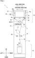
- FIG. 1 is a schematic front view of the re-winder 1.
- the re-winder 1 includes a frame 11, a yarn supplying unit 12, a winding unit 13, a yarn feeding unit 14, and a controller 15 (a control unit of the present invention).
- the re-winder 1 is configured to unwind a yarn Y from a yarn supply package Ps supported by the yarn supplying unit 12 and to re-wind the yarn Y back to a winding bobbin Bw (a bobbin of the present invention) by the winding unit 13, so as to form a wound package Pw.
- the re-winder 1 is used for, for example, re-winding the yarn Y wound on a yarn supply package Ps in a more beautiful manner and for forming a wound package Pw with a desired density.
- the frame 11 is provided to extend in the up-down direction.
- the frame 11 vertically extends on, e.g., an unillustrated floor.
- the yarn supplying unit 12 is provided at a lower part of the frame 11.
- the winding unit 13 is provided at an upper part of the frame 11, the yarn feeding unit 14 is provided at an intermediate portion of the frame 11 in the up-down direction.
- the yarn supplying unit 12 is provided at the lower part of the frame 11.
- the yarn supplying unit 12 is arranged to support the yarn supply package Ps which is formed by winding the yarn Y onto a yarn supplying bobbin Bs.
- the yarn supplying unit 12 is therefore able to supply the yarn Y.
- the winding unit 13 is configured to form the wound package Pw by winding the yarn Y onto the winding bobbin Bw.
- the winding unit 13 is provided at the upper part of the frame 11.
- the winding unit 13 includes a cradle arm 21, a winding motor 22, a traverse unit 23, and a contact roller 24.
- the cradle arm 21 is, for example, attached to the frame 11 to be swingable.
- the cradle arm 21 is arranged to support the winding bobbin Bw to be rotatable in such a way that, for example, the left-right direction is the axial direction of the winding bobbin Bw.
- a bobbin holder (not illustrated) is rotatably attached to hold the winding bobbin Bw.
- the winding motor 22 is a motor configured to rotationally drive the bobbin holder.
- the winding motor 22 is, e.g., a typical stepping motor.
- the winding motor 22 may include a rotary encoder (not illustrated) configured to detect a rotation angle of a rotational shaft (not illustrated) of the winding motor 22.
- the winding motor 22 is configured so that the number of rotations of its rotational shaft (i.e., the number of rotations per a predetermined time) is variable.
- the winding motor 22 is therefore able to change the winding speed at which the yarn Y is wound onto the winding bobbin Bw (i.e., the circumferential speed of a surface of the wound package Pw).
- the winding motor 22 is electrically connected to the controller 15 (see FIG. 2 ).
- the traverse unit 23 is configured to traverse the yarn Y along the axial direction of the winding bobbin Bw (the left-right direction in the present embodiment).
- the traverse unit 23 is provided immediately upstream of the wound package Pw in the yarn running direction.
- the traverse unit 23 includes a traverse motor 31, an endless belt 32, and a traverse guide 33.
- the traverse motor 31 is, e.g., a typical stepping motor.
- the traverse motor 31 is configured to enable its rotational shaft (not illustrated) to be rotated forward and backward.
- the traverse motor 31 may include a rotary encoder (not illustrated) configured to detect a rotation angle of the rotational shaft (not illustrated) of the traverse motor 31.
- the traverse motor 31 is configured so that the number of rotations of its rotational shaft is variable.
- the traverse motor 31 is electrically connected to the controller 15 (see FIG. 2 ).
- the endless belt 32 is a belt member to which the traverse guide 33 is attached.
- the endless belt 32 is wound onto pulleys 34 and 35 which are separated from each other in the left-right direction and a driving pulley 36 connected to the rotational shaft of the traverse motor 31, and is substantially triangular in shape when wound onto the pulleys.
- the endless belt 32 is reciprocally driven by the traverse motor 31.
- the traverse guide 33 is attached to the endless belt 32 and is provided between the pulley 34 and the pulley 35 in the left-right direction.
- the traverse guide 33 linearly and reciprocally runs in the left-right direction as the endless belt 32 is reciprocally driven by the traverse motor 31 (see arrows in FIG. 1 ).
- the traverse guide 33 traverses the yarn Y in the left-right direction (hereinafter, this direction may be referred to as a traverse direction).
- the contact roller 24 makes contact with the surface of the wound package Pw and applies a contact pressure to the surface, so as to adjust the shape of the wound package Pw.
- the contact roller 24 makes contact with the wound package Pw and is rotated by the rotation of the wound package Pw.
- the yarn feeding unit 14 is configured to send the yarn Y unwound from the yarn supply package Ps, to the winding bobbin Bw.
- the yarn feeding unit 14 is provided between the yarn supplying unit 12 and the winding unit 13 in the yarn running direction.
- the yarn feeding unit 14 includes a feed roller 41 and a roller drive motor 42.
- the feed roller 41 is a roller onto which the yarn Y is wound.
- the feed roller 41 is, e.g., a known nip roller.
- the feed roller 41 is provided on a front surface of the frame 11.
- the feed roller 41 is configured to rotate so that the yarn Y is sent to the downstream side in the yarn running direction.
- the feed roller 41 is rotationally driven by the roller drive motor 42.
- the roller drive motor 42 is, e.g., a typical stepping motor.
- the roller drive motor 42 may include a rotary encoder (not illustrated) configured to detect a rotation angle of a rotational shaft (not illustrated) of the roller drive motor 42.
- the roller drive motor 42 is configured so that the number of rotations of its rotational shaft is variable.
- the roller drive motor 42 is therefore able to change the number of rotations of the feed roller 41 (i.e., able to change the yarn feeding speed of the feed roller 41).
- the roller drive motor 42 is electrically connected to the controller 15 (see FIG. 2 ).
- tension is applied to the yarn Y by the difference between the winding speed of the winding unit 13 and the yarn feeding speed of the yarn feeding unit 14. That is, the combination of the structure of the winding unit 13 and the structure of the yarn feeding unit 14 corresponds to a tension applying unit of the present invention.
- Tension generally increases as the above-described difference between the speeds increases, and tension generally decreases as the above-described difference between the speeds decreases.
- a yarn guide 16 is provided at a lower part (on the upstream side in the yarn running direction) of the yarn feeding unit 14.
- the yarn guide 16 is provided, for example, on an extension of the central axis of the yarn supplying bobbin Bs.
- the yarn guide 16 guides the yarn Y unwound from the yarn supply package Ps, to the downstream side in the yarn running direction.
- a tension sensor 17 (a tension detection unit of the present invention) is provided at an upper part (on the downstream side in the yarn running direction) of the yarn feeding unit 14.
- the tension sensor 17 is configured to detect the tension applied to the yarn Y running from the yarn feeding unit 14 toward the winding unit 13.
- the tension sensor 17 is, e.g., an unillustrated contact-type sensor having a piezoelectric element, the disclosure is not limited to this.
- the tension sensor 17 is electrically connected to the controller 15 (see FIG. 2 ).
- the tension sensor 17 outputs a detection signal to the controller 15.
- the tension sensor 17 functions as a fulcrum guide about which the yarn Y is traversed by the traverse guide 33.
- a yarn guide (not illustrated) which functions as a fulcrum guide may be provided downstream of the tension sensor 17 in the yarn running direction.
- the controller 15 includes members such as CPU, a ROM, and a RAM (a storage unit 51; see FIG. 2 ).
- the storage unit 51 stores, for example, parameters such as an amount of the wound yarn Y, the winding speed, and the target tension which is supposed to be applied to the yarn Y.
- the controller 15 controls components by using the CPU and a program stored in the ROM, based on the parameters stored in the storage unit 51.
- the controller 15 is electrically connected to the winding motor 22, the traverse motor 31, the roller drive motor 42, and the tension sensor 17 (see FIG. 2 ).
- the controller 15 functions as a winding control unit 52, a traverse control unit 53 (a prediction information acquisition unit of the present invention), and a roller control unit 54 (a tension adjustment unit of the present invention; see FIG. 2 ).
- the controller 15 obtains winding information regarding a target value of the number of rotations of the winding bobbin Bw (or the winding speed of the yarn Y wound by the winding unit 13) from the storage unit 51.
- the controller 15 outputs a signal for controlling the torque of the winding motor 22 to the winding motor 22, based on the winding information. That is, the controller 15 functions as the winding control unit 52 configured to control the winding motor 22.
- the controller 15 further obtains target traverse information regarding a target position and target speed of the traverse guide 33, from the storage unit 51.
- the controller 15 outputs a signal for controlling the torque of the traverse motor 31 to the traverse motor 31, based on the target traverse information. That is, the controller 15 functions as the traverse control unit 53 configured to control the traverse motor 31.
- the controller 15 further obtains yarn feeding information regarding the number of rotations of the feed roller 41 (i.e., the yarn feeding speed of the yarn feeding unit 14).
- the controller 15 outputs a signal for controlling the number of rotations of the feed roller 41 (specifically, the torque of the roller drive motor 42) to the roller drive motor 42, based on the yarn feeding information. That is, the controller 15 functions as the roller control unit 54 configured to control the roller drive motor 42.
- the yarn Y unwound from the yarn supply package Ps runs toward the downstream side in the yarn running direction.
- the running yarn Y is wound onto the rotating winding bobbin Bw while being traversed in the left-right direction (traverse direction) by the traverse guide 33.
- the tension applied to the yarn Y is controlled to be close to a predetermined target tension mainly by adjusting the number of rotations of the feed roller 41 (i.e., by adjusting the yarn feeding speed of the yarn feeding unit 14).
- the tension of the yarn Y is controlled in such a way that the controller 15 (roller control unit 54) adjusts the number of rotations of the feed roller 41 based on rotation number adjustment information (adjustment information of the present invention) regarding the number of rotations of the feed roller 41.
- rotation number adjustment information adjustment information of the present invention
- the reciprocal movement of the traverse guide 33 will be described with reference to FIG. 3 .
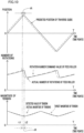
- the topmost graph in FIG. 3 shows the relationship between the position, in regard to the traverse direction, of the traverse guide 33 and time points.
- the lowermost graph in FIG. 3 shows the relationship between the speed, in regard to the traverse direction, of the traverse guide 33 and time points.
- the horizontal axis indicates time points whereas the vertical axis indicates the position of the traverse guide 33 in regard to the traverse direction.
- a direction leftward of the center of an area where the traverse guide 33 reciprocates i.e., traverse area
- a direction rightward of the center of the traverse area will be regarded as a negative direction of the vertical axis of the graph.
- the traverse guide 33 reciprocates in the left-right direction in such a way that the traverse motor 31 is driven by the controller 15.
- the symbol "T" shown in FIG. 3 indicates the cycle in which the traverse guide 33 completes a reciprocal movement once.
- the traverse guide 33 when it is at a time point of 0 in FIG. 3 , the traverse guide 33 is positioned at the center of the traverse area. In addition to that, when it is at a time point of T/4, the traverse guide 33 is positioned at the left end of the traverse area. In addition to that, when it is at a time point of T/2, the traverse guide 33 is positioned at the center of the traverse area. In addition to that, when it is at a time point of is 3T/4, the traverse guide 33 is positioned at the right end of the traverse area.
- a yarn path from the fulcrum guide (tension sensor 17 in the present embodiment) to the traverse guide 33 is the shortest. Meanwhile, when the traverse guide 33 is positioned at an end of the traverse area, the yarn path is the longest.
- the speed of the traverse guide 33 varies as shown in the lowermost graph in FIG. 3 .
- the direction of the traverse guide 33 is switched from leftward to rightward in the traverse area in regard to the traverse direction.
- the direction of the traverse guide 33 is switched from rightward to leftward in the traverse area in regard to the traverse direction.
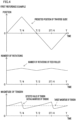
- FIG. 4 shows a graph of the relationship between the position of the traverse guide 33 and time points of a first reference example, a graph of the relationship between the number of rotations of the feed roller 41 and time points of the first reference example, and a graph of the relationship between the tension of the yarn Y and time points of the first reference example.
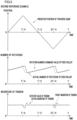
- FIG. 5 shows graphs of a second reference example.
- the topmost graph shows the relationship between the position of the traverse guide 33 and time points.
- the graph on the middle part in the up-down direction of the figure shows the relationship between the number of rotations of the feed roller 41 and time points.
- the lowermost graph shows the relationship between the tension of the yarn Y and time points.
- the magnitude of tension of the yarn Y is roughly determined by the difference between the winding speed and the yarn feeding speed as described above.
- the tension which is actually applied to the yarn Y may vary due to a reciprocal movement of the traverse guide 33. For example, when the traverse guide 33 is moved from the center toward one end side in the traverse area in regard to the traverse direction, the tension may be unintentionally increased because the length of the yarn path is increased and the yarn Y is pulled outward by the traverse guide 33 in the traverse area in regard to the traverse direction.
- the tension may be unintentionally decreased because the length of the yarn path is decreased and the yarn Y is temporarily pulled by the traverse guide 33 more gently than usual.
- control means for suppressing a variation of tension by reflecting a detection result of the tension sensor 17 onto the control of the roller drive motor 42.
- This control is, e.g., a typical feedback control.
- This control changes, e.g., the number of rotations of the feed roller 41 as shown in FIG. 4 , with the result that the yarn feeding speed is also changed.
- this control method changes the yarn feeding speed after tension has been actually varied, the following problems may occur.
- the adjustment of the yarn feeding speed may not sufficiently follow a variation of tension which is caused by the movement of the traverse guide 33.
- the actual tension see a solid line in the lower most graph in FIG. 4
- the target tension see a dotted line in the lowermost graph in FIG. 4
- control means for adjusting the yarn feeding speed by using information regarding the position and/or speed of the traverse guide 33 there is a control means for adjusting the yarn feeding speed by using information regarding the position and/or speed of the traverse guide 33.
- information regarding a variation of tension in accordance with the position of the traverse guide 33 is taken into consideration for the adjustment of the yarn feeding speed. That is, when it is predicted that the tension increases due to the movement of the traverse guide 33, the number of rotations of the feed roller 41 is controlled (see FIG. 5 ) so that the yarn feeding speed increases. Meanwhile, when it is predicted that the tension decreases, the number of rotations of the feed roller 41 is controlled (see FIG. 5 ) so that the yarn feeding speed decreases.
- time lag (delay) between when the controller 15 (roller control 54) obtains information regarding the change in the number of rotations of the feed roller 41 and when the number of rotations of the feed roller 41 is actually changed.
- the time lag is caused by factors such as the time required for calculation performed by the roller control unit 54, the inertial mass of a rotational shaft (not illustrated) of the roller drive motor 42, and the inertial mass of the feed roller 41. Due to such a delay, for example, when the traverse cycle is very short (i.e., when the movement of the traverse guide 33 is very quick), the adjustment of the yarn feeding speed may not be completed in time.
- the control means of the second reference example see FIG.
- the controller 15 of the present embodiment performs control as follows.
- the later-described method of controlling tension is a method of controlling tension during one cycle (above-described T) in which the traverse guide 33 completes a reciprocal movement once, i.e., during a reciprocal cycle of the traverse guide 33.
- the target tension is constant (see a broken line in the lowermost graph in FIG. 9 ).
- the winding speed is substantially constant during the reciprocal cycle of the traverse guide 33.
- the storage unit 51 stores, e.g., a table in which a target position and target speed of the traverse guide 33 are associated with time.
- the controller 15 may be configured to calculate the target position and/or the target speed as a function of time.
- the storage unit 51 may store a table in which one of the target position and target speed of the traverse guide 33 is associated with time. In this case, based on one of the target position and target speed of the traverse guide 33, the controller 15 may calculate the other of these.
- the controller 15 (traverse control unit 53) controls the operation of the traverse motor 31 based on information regarding the target position and target speed of the traverse guide 33.
- This information regarding the target position and target speed of the traverse guide 33 is also used as information regarding a future position (predicted position) and future speed (predicted speed) of the traverse guide 33 (hereinafter, this information will be referred to as prediction information).
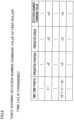
- prediction information For example, as shown in the table of FIG. 6 , x1 is a predicted position where the traverse guide 33 is supposed to be positioned at a predetermined time point t1 (first time point of the present invention). In addition to that, a predicted speed of traverse guide 33 is v1 at the time point t1.
- x2 and v2 are a predicted position and predicted speed of the traverse guide 33 at a time point t2 (second time point of the present invention) which is a time point after the elapse of a predetermined time dt from the time point t1.
- dt indicates the time shorter than the reciprocal cycle of the traverse guide 33.
- x3 and v3 are a predicted position and predicted speed of the traverse guide 33 at a time point t3 which is a time point after the elapse of a predetermined time dt from the time point t2.
- FIG. 7 shows the relationship between a predicted position of the traverse guide 33 at one time point and the desired number of rotations of the feed roller 41 at that time point.
- the predicted position of the traverse guide 33 at the time point t1 is x1 as described above.
- the desired number of rotations of the feed roller 41 is, e.g., n1 at the time point t1.
- the "n1" indicates the number of rotations of the feed roller 41 in consideration of a variation of tension of the yarn Y due to the reciprocal movement of the traverse guide 33, and this number is used for arranging the actual tension at the time point t1 to be substantially identical to the target tension.
- the desired number of rotations of the feed roller 41 is n2 at the time point t2 (predicted position x2).
- the desired number of rotations of the feed roller 41 is n3 at the time point t3 (predicted position x3).
- time lag (delay) between when the controller 15 (roller control unit 54) obtains information regarding the adjustment of the number of rotations of the feed roller 41 (i.e., rotation number adjustment information) and when the number of rotations of the feed roller 41 is actually changed.
- a time lag is substantially equal to, e.g., an above-described predetermined time dt.
- the roller control unit 54 controls the yarn feeding unit 14 as follows.
- the controller 15 is set as follows on the premise that a predetermined time dt is substantially equal to the above time lag.
- the storage unit 51 stores, e.g., a function used when a command value regarding the number of rotations of the feed roller 41 (hereinafter, this value will be referred to as a rotation number command value) is calculated based on information regarding a predicated future position and predicted future speed of the traverse guide 33 (prediction information).
- This function is, e.g., a function with a fixed coefficient. (That is, as the same prediction information is input, this function outputs a constant rotation number command value).
- the roller control unit 54 receives prediction information from the traverse control unit 53, and calculates a rotation number command value with use of the function.
- the roller control unit 54 calculates a rotation number command value corresponding to the time point t1 (i.e., calculates information regarding a control signal which is supposed to be output at the time point t1 from the roller control unit 54 to the roller drive motor 42), the roller control unit 54 uses prediction information corresponding to the time point t2 which is a time point after the elapse of a predetermined time dt from the time point t1.
- the prediction information corresponding to the time point t2 is information regarding a predicted position and predicted speed of the traverse guide 33 at the time point t2.
- the traverse control unit 53 swiftly sends prediction information to the roller control unit 54, the prediction information corresponding to the time point t2 is available for calculating a rotation number command value corresponding to the time point t1.
- the rotation number command value corresponding to the time point t1 is calculated as n2 (see the table of FIG. 8 and the graph on the middle part of FIG. 9 ). That is, the roller control unit 54 obtains a rotation number command value regarding the predicted position x2 and predicted speed v2 of the traverse guide 33 at the time point t2 (i.e., obtains n2), as rotation number adjustment information corresponding to the time point t1.
- the rotation number adjustment information corresponding to the time point t1 is obtained in association with prediction information corresponding to the time point t2 which is a time point after the elapse of a predetermined time dt from the time point t1.
- roller control unit 54 to output a control signal, used for adjusting the number of rotations of the feed roller 41 to n2, at a time point earlier than the time point t2 by a predetermined time dt (see broken lines which vertically extend at the central portion of FIG. 9 ).
- a control signal used for adjusting the number of rotations of the feed roller 41 to n2 at a time point earlier than the time point t2 by a predetermined time dt (see broken lines which vertically extend at the central portion of FIG. 9 ).
- a command value regarding the number of rotations of the feed roller 41 see a broken line in the graph on the middle part of FIG.
- the roller control unit 54 may obtain a rotation number command value further in consideration of a detection result of the tension sensor 17. That is, the roller control unit 54 may finally calculate (generate) a command value regarding the number of rotations of the feed roller 41 (to be more specific, a command value regarding the torque of the roller drive motor 42) based on the above-described rotation number command value and a detection result of the tension sensor 17. Because of this, a variation of tension due to disturbance factors except the reciprocal movement of the traverse guide 33 is also suppressed.
- rotation number adjustment information corresponding to the time point t1 is obtained in association with prediction information corresponding to the time point t2 which is a time point after the elapse of a predetermined time dt from the time point t1 (i.e., t2 is later than t1 by the predetermined time dt) .
- This enables the roller control unit 54 to output a signal at a time point which is earlier than the time point t2 by a predetermined time dt.
- the signal is related to the adjustment, which is supposed to be executed at the time point t2, of the number of rotations of the feed roller 41 (i.e., the adjustment of tension). Because of this, the above-described delay is compensated, and thus tension is adjusted at an appropriate timing. Therefore, a variation of tension due to the reciprocal movement of the traverse guide 33 is effectively suppressed.
- a predetermined time dt is shorter than the reciprocal cycle of the traverse guide 33. Because of this, it is possible to suppress the increase in difference between a predicted position of the traverse guide 33 at the time point t2 and an actual position of the traverse guide 33 at the time point t2. In this regard, the predicted position is predicted at the time point t1. Tension is therefore finely controllable.
- the yarn feeding speed of the yarn feeding unit 14 is controlled so as to control tension. Therefore, the control of tension is simplified as compared to cases where the winding unit 13 is controlled in order to control tension.
Landscapes
- Engineering & Computer Science (AREA)
- Textile Engineering (AREA)
- Winding Filamentary Materials (AREA)
- Tension Adjustment In Filamentary Materials (AREA)
- Filamentary Materials, Packages, And Safety Devices Therefor (AREA)
Description
- The present invention relates to a yarn winder.
-
WO2020075383A1 discloses a yarn winder configured to wind a running yarn onto a bobbin, so as to form a package. Specifically, the yarn winder includes a traverse unit having a traverse guide for traversing the yarn along the axial direction of the bobbin, a winding unit for rotating the bobbin, and a roller (feed roller) for feeding the yarn to the winding unit. Tension is applied to the yarn by the difference between the winding speed at which the yarn is wound onto the bobbin and the yarn feeding speed at which the yarn is sent by the feed roller. (In other words, the yarn winder includes a tension applying unit configured to apply tension to the yarn which is wound onto the bobbin) . Because tension is controlled to be at a predetermined value in this way, a package with a predetermined winding density is formed in accordance with the use. - The tension which is actually applied to the yarn may vary due to a reciprocal movement of the traverse guide. For example, when the traverse guide is moved from the center toward one end side in an area where the traverse guide reciprocates in a predetermined traverse direction, the tension may be unintentionally increased because the length of a yarn path is increased and the yarn is pulled outward by the traverse guide in the area where the traverse guide reciprocates in the traverse direction. Meanwhile, when the direction of the traverse guide is switched from the outward to the inward in the area where the traverse guide reciprocates in the traverse direction, the tension may be unintentionally decreased because the length of the yarn path is decreased and the yarn is temporarily pulled by the traverse guide more gently than usual. This variation of tension is suppressed in such a way that, for example, a controller (tension adjustment unit) such as a computer controls the yarn feeding speed. For example,
EP1318097B1 has proposed a means for controlling the yarn feeding speed by using information regarding a position of the traverse guide.EP 1 520 827 A1 discloses a yarn winder according to the preamble of claim 1. - There is some time lag (delay) between acquisition of information for the tension adjustment in consideration of the position (and/or speed) of a traverse guide by a tension adjustment unit and actual adjustment of tension. The time lag is caused by, for example, the time required for calculation performed by the tension adjustment unit and the time required for the response of a tension applying unit. Due to such a delay, for example, when the traverse cycle is short (i.e., the movement of the traverse guide is quick), actual tension adjustment may not sufficiently follow a variation of tension which is caused by the movement of the traverse guide. This may cause a problem in which a variation of tension is not sufficiently suppressed.
WO2020075383A1 andEP1318097B1 are silent on the above-described time lag. - An object of the present invention is to effectively suppress a variation of tension due to the reciprocal movement of a traverse guide.
- According to a first aspect of the invention, a yarn winder configured to wind a running yarn onto a bobbin includes: a traverse unit which includes a traverse guide for traversing the yarn along an axial direction of the bobbin; a tension applying unit configured to apply tension to the yarn which is to be wound onto the bobbin; and a control unit, the control unit includes: a prediction information acquisition unit configured to obtain prediction information regarding at least one of a predicted future position and predicted future speed of the traverse guide; and a tension adjustment unit configured to control the tension applying unit based on adjustment information regarding the adjustment of the tension, and the tension adjustment unit obtains the adjustment information corresponding to a predetermined first time point in association with the prediction information corresponding to a second time point which is a time point after the elapse of a predetermined time from the first time point.
- In the present invention, the adjustment information corresponding to the first time point is obtained in association with the prediction information corresponding to the second time point which is a time point after the elapse of a predetermined time (i.e., which is a predetermined time later) from the first time point. In this regard, "obtained in association with" indicates that there is some relation (such as calculation and link) between the adjustment information corresponding to the first time point and the prediction information corresponding to the second time point. The predetermined time can be set or determined in consideration of the above-described time lag (delay).
- This enables the tension adjustment unit to output a signal at a time point earlier than the second time point by a predetermined time. The signal is related to the adjustment, which is supposed to be actually executed at the second time point, of the tension. Because of this, the above-described delay is compensated, and thus the tension is adjusted at an appropriate timing. Therefore, the variation of the tension due to the reciprocal movement of the traverse guide is effectively suppressed.
- According to a second aspect of the invention, the yarn winder of the first aspect is arranged such that the predetermined time is shorter than a reciprocal cycle of the traverse guide.
- In the present invention, the predetermined time is shorter than the reciprocal cycle of the traverse guide. Because of this, it is possible to suppress the increase in difference between a predicted position and/or predicted speed of the traverse guide at the second time point and an actual position and/or actual speed of the traverse guide at the second time point. In this regard, the predicted position and the predicted speed are predicted at the first time point. The tension is therefore finely controllable.
- According to a third aspect of the invention, the yarn winder of the first or second aspect further includes a tension detection unit configured to detect the tension applied to the yarn, and the tension adjustment unit obtains the adjustment information based on a detection result of the tension detection unit.
- The tension of the yarn may be varied not only due to the reciprocal movement of the traverse guide but also due to other disturbance factors. By obtaining the adjustment information based on a detection result of the tension detection unit, it is possible to perform a feedback control so that the magnitude of the tension is close to a predetermined target value in the present invention. Therefore, because the variation of the tension due to disturbance factors except the reciprocal movement of the traverse guide is also suppressed, the tension is further stabilized.
- According to a fourth aspect of the invention, the yarn winder of any one of the first to third aspects is arranged such that the tension applying unit includes: a winding unit configured to wind the yarn onto the bobbin; and a yarn feeding unit configured to send the yarn to the bobbin, the tension applying unit applies the tension to the yarn by utilizing a difference between a winding speed at which the yarn is wound onto the bobbin by the winding unit and a yarn feeding speed at which the yarn is sent to the bobbin by the yarn feeding unit, and the tension adjustment unit controls the tension by controlling the yarn feeding unit.
- When the tension is applied to the yarn Y by difference between the winding speed and the yarn feeding speed, the tension can be controlled by controlling the winding speed. However, when the tension is controlled by controlling the winding speed, a winding angle (this angle is a helix angle) of the yarn may be unintentionally varied. In this case, it is further necessary to control the traverse unit in order to suppress the variation of a helix angle. This may complicate the control. In the present invention, because the tension is controlled by controlling the yarn feeding speed, the control of the tension is simplified as compared to cases where the winding unit is controlled in order to control the tension.
- According to a fifth aspect of the invention, the yarn winder of any one of the first to fourth aspects is arranged such that the control unit changes a target value of the tension during the reciprocal cycle of the traverse guide.
- The control in which the variation of the tension is suppressed in consideration of the above-described time lag in the present invention is especially effective in the structure configured so that a target value of the tension is changed during the reciprocal cycle of the traverse guide.
- According to a sixth aspect of the invention, in a traverse direction in which the traverse guide moves, the yarn winder of the fifth aspect is arranged such that the control unit arranges a target value of the tension when the traverse guide is positioned at one end in a traverse area where the traverse guide reciprocates in regard to the traverse direction to be lower than a target value of the tension when the traverse guide is positioned at a center in the traverse area.
- When the tension of the yarn is high while the traverse guide is positioned at one end side in the traverse area, the yarn may be unintentionally pulled inward in the axial direction of the bobbin at the time of changing the direction of the traverse guide. As a result, an amount of the yarn wound onto the inside of a target position in the axial direction of the bobbin may be increased so as to deteriorate the shape of a package. In the present invention, the tension when the traverse guide is positioned at one end side in the traverse area is arranged to be low. It is therefore possible to suppress the yarn from being unintentionally pulled inward in the axial direction of the bobbin at the time of changing the direction of the traverse guide.
-
-
FIG. 1 is a schematic front view of a re-winder of an embodiment. -
FIG. 2 shows an electric structure of the re-winder. -
FIG. 3 shows a graph of the relationship between a position of a traverse guide and time points and a graph of the relationship between the speed of the traverse guide and time points. -
FIG. 4 shows a graph of the relationship between the position of the traverse guide and time points of a first reference example, a graph of the relationship between the number of rotations of a feed roller and time points of the first reference example, and a graph of the relationship between the tension of a yarn and time points of the first reference example. -
FIG. 5 shows a graph of the relationship between the position of the traverse guide and time points of a second reference example, a graph of the relationship between the number of rotations of the feed roller and time points of the second reference example, and a graph of the relationship between the tension of the yarn and time points of the second reference example. -
FIG. 6 is a table showing the correspondence between a predicted position of the traverse guide, a predicted speed of the traverse guide, and time points. -
FIG. 7 is a table showing the relationship between the predicted position of the traverse guide at one time point and the desired number of rotations of the feed roller at that time point. -
FIG. 8 is a table showing the relationship between a command value regarding the number of rotations of the feed roller and time points in consideration of a predetermined time lag. -
FIG. 9 shows a graph of the relationship between the position of the traverse guide of the present embodiment and time points, a graph of the relationship between the number of rotations of the feed roller of the present embodiment and time points, and a graph of the relationship between the tension of the yarn of the present embodiment and time points. -
FIG. 10 shows a graph of the relationship between a position of a traverse guide of a modification and time points, a graph of the relationship between the number of rotations of a feed roller of the modification and time points, and a graph of the relationship between the tension of a yarn of the modification and time points. - The following will describe an embodiment of the present invention with reference to
FIG. 1 to FIG. 9 . An up-down direction and a left-right direction shown inFIG. 1 will be referred to as an up-down direction and a left-right direction of a re-winder 1. A direction orthogonal to both the up-down direction and the left-right direction (i.e., a direction perpendicular to the plane ofFIG. 1 ) will be referred to as a front-rear direction. A direction in which a yarn Y runs will be referred to as a yarn running direction. - To begin with, the structure of a re-winder 1 (a yarn winder of the present invention) of the present embodiment will be described with reference to
FIG. 1. FIG. 1 is a schematic front view of the re-winder 1. As shown inFIG. 1 , the re-winder 1 includes aframe 11, ayarn supplying unit 12, a windingunit 13, ayarn feeding unit 14, and a controller 15 (a control unit of the present invention). The re-winder 1 is configured to unwind a yarn Y from a yarn supply package Ps supported by theyarn supplying unit 12 and to re-wind the yarn Y back to a winding bobbin Bw (a bobbin of the present invention) by the windingunit 13, so as to form a wound package Pw. To be more specific, the re-winder 1 is used for, for example, re-winding the yarn Y wound on a yarn supply package Ps in a more beautiful manner and for forming a wound package Pw with a desired density. - The
frame 11 is provided to extend in the up-down direction. Theframe 11 vertically extends on, e.g., an unillustrated floor. At a lower part of theframe 11, theyarn supplying unit 12 is provided. At an upper part of theframe 11, the windingunit 13 is provided. At an intermediate portion of theframe 11 in the up-down direction, theyarn feeding unit 14 is provided. - The
yarn supplying unit 12 is provided at the lower part of theframe 11. Theyarn supplying unit 12 is arranged to support the yarn supply package Ps which is formed by winding the yarn Y onto a yarn supplying bobbin Bs. Theyarn supplying unit 12 is therefore able to supply the yarn Y. - The winding
unit 13 is configured to form the wound package Pw by winding the yarn Y onto the winding bobbin Bw. The windingunit 13 is provided at the upper part of theframe 11. The windingunit 13 includes acradle arm 21, a windingmotor 22, atraverse unit 23, and acontact roller 24. - The
cradle arm 21 is, for example, attached to theframe 11 to be swingable. Thecradle arm 21 is arranged to support the winding bobbin Bw to be rotatable in such a way that, for example, the left-right direction is the axial direction of the winding bobbin Bw. For example, at a leading end portion of thecradle arm 21, a bobbin holder (not illustrated) is rotatably attached to hold the winding bobbin Bw. The windingmotor 22 is a motor configured to rotationally drive the bobbin holder. The windingmotor 22 is, e.g., a typical stepping motor. The windingmotor 22 may include a rotary encoder (not illustrated) configured to detect a rotation angle of a rotational shaft (not illustrated) of the windingmotor 22. The windingmotor 22 is configured so that the number of rotations of its rotational shaft (i.e., the number of rotations per a predetermined time) is variable. The windingmotor 22 is therefore able to change the winding speed at which the yarn Y is wound onto the winding bobbin Bw (i.e., the circumferential speed of a surface of the wound package Pw). The windingmotor 22 is electrically connected to the controller 15 (seeFIG. 2 ). - The
traverse unit 23 is configured to traverse the yarn Y along the axial direction of the winding bobbin Bw (the left-right direction in the present embodiment). Thetraverse unit 23 is provided immediately upstream of the wound package Pw in the yarn running direction. Thetraverse unit 23 includes atraverse motor 31, anendless belt 32, and atraverse guide 33. - The
traverse motor 31 is, e.g., a typical stepping motor. Thetraverse motor 31 is configured to enable its rotational shaft (not illustrated) to be rotated forward and backward. Thetraverse motor 31 may include a rotary encoder (not illustrated) configured to detect a rotation angle of the rotational shaft (not illustrated) of thetraverse motor 31. Thetraverse motor 31 is configured so that the number of rotations of its rotational shaft is variable. Thetraverse motor 31 is electrically connected to the controller 15 (seeFIG. 2 ). Theendless belt 32 is a belt member to which thetraverse guide 33 is attached. Theendless belt 32 is wound ontopulleys pulley 36 connected to the rotational shaft of thetraverse motor 31, and is substantially triangular in shape when wound onto the pulleys. Theendless belt 32 is reciprocally driven by thetraverse motor 31. Thetraverse guide 33 is attached to theendless belt 32 and is provided between thepulley 34 and thepulley 35 in the left-right direction. Thetraverse guide 33 linearly and reciprocally runs in the left-right direction as theendless belt 32 is reciprocally driven by the traverse motor 31 (see arrows inFIG. 1 ). As a result, thetraverse guide 33 traverses the yarn Y in the left-right direction (hereinafter, this direction may be referred to as a traverse direction). - The
contact roller 24 makes contact with the surface of the wound package Pw and applies a contact pressure to the surface, so as to adjust the shape of the wound package Pw. Thecontact roller 24 makes contact with the wound package Pw and is rotated by the rotation of the wound package Pw. - The
yarn feeding unit 14 is configured to send the yarn Y unwound from the yarn supply package Ps, to the winding bobbin Bw. Theyarn feeding unit 14 is provided between theyarn supplying unit 12 and the windingunit 13 in the yarn running direction. Theyarn feeding unit 14 includes afeed roller 41 and aroller drive motor 42. - The
feed roller 41 is a roller onto which the yarn Y is wound. Thefeed roller 41 is, e.g., a known nip roller. Thefeed roller 41 is provided on a front surface of theframe 11. Thefeed roller 41 is configured to rotate so that the yarn Y is sent to the downstream side in the yarn running direction. Thefeed roller 41 is rotationally driven by theroller drive motor 42. Theroller drive motor 42 is, e.g., a typical stepping motor. Theroller drive motor 42 may include a rotary encoder (not illustrated) configured to detect a rotation angle of a rotational shaft (not illustrated) of theroller drive motor 42. Theroller drive motor 42 is configured so that the number of rotations of its rotational shaft is variable. Theroller drive motor 42 is therefore able to change the number of rotations of the feed roller 41 (i.e., able to change the yarn feeding speed of the feed roller 41). Theroller drive motor 42 is electrically connected to the controller 15 (seeFIG. 2 ). In the present embodiment, tension is applied to the yarn Y by the difference between the winding speed of the windingunit 13 and the yarn feeding speed of theyarn feeding unit 14. That is, the combination of the structure of the windingunit 13 and the structure of theyarn feeding unit 14 corresponds to a tension applying unit of the present invention. Tension generally increases as the above-described difference between the speeds increases, and tension generally decreases as the above-described difference between the speeds decreases. - At a lower part (on the upstream side in the yarn running direction) of the
yarn feeding unit 14, ayarn guide 16 is provided. Theyarn guide 16 is provided, for example, on an extension of the central axis of the yarn supplying bobbin Bs. Theyarn guide 16 guides the yarn Y unwound from the yarn supply package Ps, to the downstream side in the yarn running direction. At an upper part (on the downstream side in the yarn running direction) of theyarn feeding unit 14, a tension sensor 17 (a tension detection unit of the present invention) is provided. Thetension sensor 17 is configured to detect the tension applied to the yarn Y running from theyarn feeding unit 14 toward the windingunit 13. While thetension sensor 17 is, e.g., an unillustrated contact-type sensor having a piezoelectric element, the disclosure is not limited to this. Thetension sensor 17 is electrically connected to the controller 15 (seeFIG. 2 ). Thetension sensor 17 outputs a detection signal to thecontroller 15. Thetension sensor 17 functions as a fulcrum guide about which the yarn Y is traversed by thetraverse guide 33. A yarn guide (not illustrated) which functions as a fulcrum guide may be provided downstream of thetension sensor 17 in the yarn running direction. - The
controller 15 includes members such as CPU, a ROM, and a RAM (astorage unit 51; seeFIG. 2 ). Thestorage unit 51 stores, for example, parameters such as an amount of the wound yarn Y, the winding speed, and the target tension which is supposed to be applied to the yarn Y. Thecontroller 15 controls components by using the CPU and a program stored in the ROM, based on the parameters stored in thestorage unit 51. Thecontroller 15 is electrically connected to the windingmotor 22, thetraverse motor 31, theroller drive motor 42, and the tension sensor 17 (seeFIG. 2 ). - As described later, the
controller 15 functions as a windingcontrol unit 52, a traverse control unit 53 (a prediction information acquisition unit of the present invention), and a roller control unit 54 (a tension adjustment unit of the present invention; seeFIG. 2 ). To begin with, thecontroller 15 obtains winding information regarding a target value of the number of rotations of the winding bobbin Bw (or the winding speed of the yarn Y wound by the winding unit 13) from thestorage unit 51. Thecontroller 15 outputs a signal for controlling the torque of the windingmotor 22 to the windingmotor 22, based on the winding information. That is, thecontroller 15 functions as the windingcontrol unit 52 configured to control the windingmotor 22. - The
controller 15 further obtains target traverse information regarding a target position and target speed of thetraverse guide 33, from thestorage unit 51. Thecontroller 15 outputs a signal for controlling the torque of thetraverse motor 31 to thetraverse motor 31, based on the target traverse information. That is, thecontroller 15 functions as thetraverse control unit 53 configured to control thetraverse motor 31. - The
controller 15 further obtains yarn feeding information regarding the number of rotations of the feed roller 41 (i.e., the yarn feeding speed of the yarn feeding unit 14). Thecontroller 15 outputs a signal for controlling the number of rotations of the feed roller 41 (specifically, the torque of the roller drive motor 42) to theroller drive motor 42, based on the yarn feeding information. That is, thecontroller 15 functions as theroller control unit 54 configured to control theroller drive motor 42. - In the re-winder 1 arranged as described above, the yarn Y unwound from the yarn supply package Ps runs toward the downstream side in the yarn running direction. The running yarn Y is wound onto the rotating winding bobbin Bw while being traversed in the left-right direction (traverse direction) by the
traverse guide 33. The tension applied to the yarn Y is controlled to be close to a predetermined target tension mainly by adjusting the number of rotations of the feed roller 41 (i.e., by adjusting the yarn feeding speed of the yarn feeding unit 14). That is, the tension of the yarn Y is controlled in such a way that the controller 15 (roller control unit 54) adjusts the number of rotations of thefeed roller 41 based on rotation number adjustment information (adjustment information of the present invention) regarding the number of rotations of thefeed roller 41. The details of tension control will be given later. - The reciprocal movement of the
traverse guide 33 will be described with reference toFIG. 3 . The topmost graph inFIG. 3 shows the relationship between the position, in regard to the traverse direction, of thetraverse guide 33 and time points. The lowermost graph inFIG. 3 shows the relationship between the speed, in regard to the traverse direction, of thetraverse guide 33 and time points. - In the topmost graph in
FIG. 3 , the horizontal axis indicates time points whereas the vertical axis indicates the position of thetraverse guide 33 in regard to the traverse direction. For convenience, a direction leftward of the center of an area where thetraverse guide 33 reciprocates (i.e., traverse area) will be regarded as a positive direction of the vertical axis of the graph. A direction rightward of the center of the traverse area will be regarded as a negative direction of the vertical axis of the graph. Thetraverse guide 33 reciprocates in the left-right direction in such a way that thetraverse motor 31 is driven by thecontroller 15. The symbol "T" shown inFIG. 3 indicates the cycle in which thetraverse guide 33 completes a reciprocal movement once. To be more specific, when it is at a time point of 0 inFIG. 3 , thetraverse guide 33 is positioned at the center of the traverse area. In addition to that, when it is at a time point of T/4, thetraverse guide 33 is positioned at the left end of the traverse area. In addition to that, when it is at a time point of T/2, thetraverse guide 33 is positioned at the center of the traverse area. In addition to that, when it is at a time point of is 3T/4, thetraverse guide 33 is positioned at the right end of the traverse area. When thetraverse guide 33 is positioned at the center of the traverse area, a yarn path from the fulcrum guide (tension sensor 17 in the present embodiment) to thetraverse guide 33 is the shortest. Meanwhile, when thetraverse guide 33 is positioned at an end of the traverse area, the yarn path is the longest. - The speed of the
traverse guide 33 varies as shown in the lowermost graph inFIG. 3 . To be more specific, when it is at a time point of T/4 inFIG. 3 , the direction of thetraverse guide 33 is switched from leftward to rightward in the traverse area in regard to the traverse direction. In addition to that, when it is at a time point of 3T/4, the direction of thetraverse guide 33 is switched from rightward to leftward in the traverse area in regard to the traverse direction. - The following will describe a variation of tension due to the reciprocal movement of the
traverse guide 33 with reference toFIG. 4 andFIG. 5 .FIG. 4 shows a graph of the relationship between the position of thetraverse guide 33 and time points of a first reference example, a graph of the relationship between the number of rotations of thefeed roller 41 and time points of the first reference example, and a graph of the relationship between the tension of the yarn Y and time points of the first reference example.FIG. 5 shows graphs of a second reference example. InFIG. 4 andFIG. 5 , the topmost graph shows the relationship between the position of thetraverse guide 33 and time points. In addition to that, the graph on the middle part in the up-down direction of the figure shows the relationship between the number of rotations of thefeed roller 41 and time points. In addition to that, the lowermost graph shows the relationship between the tension of the yarn Y and time points. - The magnitude of tension of the yarn Y is roughly determined by the difference between the winding speed and the yarn feeding speed as described above. However, the tension which is actually applied to the yarn Y may vary due to a reciprocal movement of the
traverse guide 33. For example, when thetraverse guide 33 is moved from the center toward one end side in the traverse area in regard to the traverse direction, the tension may be unintentionally increased because the length of the yarn path is increased and the yarn Y is pulled outward by thetraverse guide 33 in the traverse area in regard to the traverse direction. Meanwhile, when the direction of thetraverse guide 33 is switched from the outward to the inward at one end side in the traverse area in regard to the traverse direction, the tension may be unintentionally decreased because the length of the yarn path is decreased and the yarn Y is temporarily pulled by thetraverse guide 33 more gently than usual. - In order to suppress this variation of tension, many types of means have been proposed. As a first reference example, there is a control means for suppressing a variation of tension by reflecting a detection result of the
tension sensor 17 onto the control of theroller drive motor 42. This control is, e.g., a typical feedback control. This control changes, e.g., the number of rotations of thefeed roller 41 as shown inFIG. 4 , with the result that the yarn feeding speed is also changed. However, because this control method changes the yarn feeding speed after tension has been actually varied, the following problems may occur. For example, when the traverse cycle is short (i.e., the movement of the traverse guide is quick), the adjustment of the yarn feeding speed may not sufficiently follow a variation of tension which is caused by the movement of thetraverse guide 33. In this case, because a variation of tension is not sufficiently suppressed, the actual tension (see a solid line in the lower most graph inFIG. 4 ) is different from the target tension (see a dotted line in the lowermost graph inFIG. 4 ) as shown inFIG. 4 . - As a second reference example, there is a control means for adjusting the yarn feeding speed by using information regarding the position and/or speed of the
traverse guide 33. In this control method, information regarding a variation of tension in accordance with the position of thetraverse guide 33 is taken into consideration for the adjustment of the yarn feeding speed. That is, when it is predicted that the tension increases due to the movement of thetraverse guide 33, the number of rotations of thefeed roller 41 is controlled (seeFIG. 5 ) so that the yarn feeding speed increases. Meanwhile, when it is predicted that the tension decreases, the number of rotations of thefeed roller 41 is controlled (seeFIG. 5 ) so that the yarn feeding speed decreases. - However, there is some time lag (delay) between when the controller 15 (roller control 54) obtains information regarding the change in the number of rotations of the
feed roller 41 and when the number of rotations of thefeed roller 41 is actually changed. The time lag is caused by factors such as the time required for calculation performed by theroller control unit 54, the inertial mass of a rotational shaft (not illustrated) of theroller drive motor 42, and the inertial mass of thefeed roller 41. Due to such a delay, for example, when the traverse cycle is very short (i.e., when the movement of thetraverse guide 33 is very quick), the adjustment of the yarn feeding speed may not be completed in time. The control means of the second reference example (seeFIG. 5 ) may therefore suppress a variation of tension as compared to the means of the first reference example (seeFIG. 4 ), but may not sufficiently suppress a variation of tension (seeFIG. 5 ). In order to effectively suppress a variation of tension due to the reciprocal movement of thetraverse guide 33, thecontroller 15 of the present embodiment performs control as follows. - The following will describe a specific method in which the
controller 15 controls tension, with reference toFIG. 6 to FIG. 9 . The later-described method of controlling tension is a method of controlling tension during one cycle (above-described T) in which thetraverse guide 33 completes a reciprocal movement once, i.e., during a reciprocal cycle of thetraverse guide 33. In this embodiment, the target tension is constant (see a broken line in the lowermost graph inFIG. 9 ). In the present embodiment, the winding speed is substantially constant during the reciprocal cycle of thetraverse guide 33. - The
storage unit 51 stores, e.g., a table in which a target position and target speed of thetraverse guide 33 are associated with time. Alternatively, for example, thecontroller 15 may be configured to calculate the target position and/or the target speed as a function of time. Alternatively, thestorage unit 51 may store a table in which one of the target position and target speed of thetraverse guide 33 is associated with time. In this case, based on one of the target position and target speed of thetraverse guide 33, thecontroller 15 may calculate the other of these. As such, the controller 15 (traverse control unit 53) controls the operation of thetraverse motor 31 based on information regarding the target position and target speed of thetraverse guide 33. - This information regarding the target position and target speed of the
traverse guide 33 is also used as information regarding a future position (predicted position) and future speed (predicted speed) of the traverse guide 33 (hereinafter, this information will be referred to as prediction information). For example, as shown in the table ofFIG. 6 , x1 is a predicted position where thetraverse guide 33 is supposed to be positioned at a predetermined time point t1 (first time point of the present invention). In addition to that, a predicted speed oftraverse guide 33 is v1 at the time point t1. Furthermore, x2 and v2 are a predicted position and predicted speed of thetraverse guide 33 at a time point t2 (second time point of the present invention) which is a time point after the elapse of a predetermined time dt from the time point t1. In this regard, "dt" indicates the time shorter than the reciprocal cycle of thetraverse guide 33. Likewise, x3 and v3 are a predicted position and predicted speed of thetraverse guide 33 at a time point t3 which is a time point after the elapse of a predetermined time dt from the time point t2. -
FIG. 7 shows the relationship between a predicted position of thetraverse guide 33 at one time point and the desired number of rotations of thefeed roller 41 at that time point. For example, the predicted position of thetraverse guide 33 at the time point t1 is x1 as described above. The desired number of rotations of thefeed roller 41 is, e.g., n1 at the time point t1. The "n1" indicates the number of rotations of thefeed roller 41 in consideration of a variation of tension of the yarn Y due to the reciprocal movement of thetraverse guide 33, and this number is used for arranging the actual tension at the time point t1 to be substantially identical to the target tension. Likewise, the desired number of rotations of thefeed roller 41 is n2 at the time point t2 (predicted position x2). In addition to that, the desired number of rotations of thefeed roller 41 is n3 at the time point t3 (predicted position x3). - As described above, there is some time lag (delay) between when the controller 15 (roller control unit 54) obtains information regarding the adjustment of the number of rotations of the feed roller 41 (i.e., rotation number adjustment information) and when the number of rotations of the
feed roller 41 is actually changed. Assume that such a time lag is substantially equal to, e.g., an above-described predetermined time dt. In this case, theroller control unit 54 controls theyarn feeding unit 14 as follows. In other words, thecontroller 15 is set as follows on the premise that a predetermined time dt is substantially equal to the above time lag. - The
storage unit 51 stores, e.g., a function used when a command value regarding the number of rotations of the feed roller 41 (hereinafter, this value will be referred to as a rotation number command value) is calculated based on information regarding a predicated future position and predicted future speed of the traverse guide 33 (prediction information). This function is, e.g., a function with a fixed coefficient. (That is, as the same prediction information is input, this function outputs a constant rotation number command value). Theroller control unit 54 receives prediction information from thetraverse control unit 53, and calculates a rotation number command value with use of the function. When theroller control unit 54 calculates a rotation number command value corresponding to the time point t1 (i.e., calculates information regarding a control signal which is supposed to be output at the time point t1 from theroller control unit 54 to the roller drive motor 42), theroller control unit 54 uses prediction information corresponding to the time point t2 which is a time point after the elapse of a predetermined time dt from the time point t1. The prediction information corresponding to the time point t2 is information regarding a predicted position and predicted speed of thetraverse guide 33 at the time point t2. - To be more specific, because the
traverse control unit 53 swiftly sends prediction information to theroller control unit 54, the prediction information corresponding to the time point t2 is available for calculating a rotation number command value corresponding to the time point t1. As a result, the rotation number command value corresponding to the time point t1 is calculated as n2 (see the table ofFIG. 8 and the graph on the middle part ofFIG. 9 ). That is, theroller control unit 54 obtains a rotation number command value regarding the predicted position x2 and predicted speed v2 of thetraverse guide 33 at the time point t2 (i.e., obtains n2), as rotation number adjustment information corresponding to the time point t1. In other words, the rotation number adjustment information corresponding to the time point t1 is obtained in association with prediction information corresponding to the time point t2 which is a time point after the elapse of a predetermined time dt from the time point t1. - This enables the
roller control unit 54 to output a control signal, used for adjusting the number of rotations of thefeed roller 41 to n2, at a time point earlier than the time point t2 by a predetermined time dt (see broken lines which vertically extend at the central portion ofFIG. 9 ). To be more specific, it is necessary to arrange the actual number of rotations of the feed roller 41 (see a solid line in the graph on the middle part ofFIG. 9 ) to be maximized when thetraverse guide 33 is about to reach an outer end in the traverse area in regard to the traverse direction (at the time point t2 inFIG. 9 ). To achieve this, a command value regarding the number of rotations of the feed roller 41 (see a broken line in the graph on the middle part ofFIG. 9 ) is maximized at the time point t1 which precedes the time point t2 by a predetermined time dt. This compensates the above-described time lag (delay), and thus the number of rotations of thefeed roller 41 is adjusted at an appropriate timing. That is, tension is adjusted at an appropriate timing so as to effectively suppress a variation of tension. - In this regard, the
roller control unit 54 may obtain a rotation number command value further in consideration of a detection result of thetension sensor 17. That is, theroller control unit 54 may finally calculate (generate) a command value regarding the number of rotations of the feed roller 41 (to be more specific, a command value regarding the torque of the roller drive motor 42) based on the above-described rotation number command value and a detection result of thetension sensor 17. Because of this, a variation of tension due to disturbance factors except the reciprocal movement of thetraverse guide 33 is also suppressed. - As described above, rotation number adjustment information corresponding to the time point t1 is obtained in association with prediction information corresponding to the time point t2 which is a time point after the elapse of a predetermined time dt from the time point t1 (i.e., t2 is later than t1 by the predetermined time dt) . This enables the
roller control unit 54 to output a signal at a time point which is earlier than the time point t2 by a predetermined time dt. The signal is related to the adjustment, which is supposed to be executed at the time point t2, of the number of rotations of the feed roller 41 (i.e., the adjustment of tension). Because of this, the above-described delay is compensated, and thus tension is adjusted at an appropriate timing. Therefore, a variation of tension due to the reciprocal movement of thetraverse guide 33 is effectively suppressed. - A predetermined time dt is shorter than the reciprocal cycle of the
traverse guide 33. Because of this, it is possible to suppress the increase in difference between a predicted position of thetraverse guide 33 at the time point t2 and an actual position of thetraverse guide 33 at the time point t2. In this regard, the predicted position is predicted at the time point t1. Tension is therefore finely controllable. - By obtaining rotation number adjustment information based on a detection result of the
tension sensor 17, it is possible to perform a feedback control so that the tension is close to a predetermined target value. Therefore, because a variation of tension due to disturbance factors except the reciprocal movement of thetraverse guide 33 is also suppressed, tension is further stabilized. - In the present embodiment, the yarn feeding speed of the
yarn feeding unit 14 is controlled so as to control tension. Therefore, the control of tension is simplified as compared to cases where the windingunit 13 is controlled in order to control tension. - The following will describe modifications of the above-described embodiment. The members identical with those in the embodiment above will be denoted by the same reference numerals, and the explanations thereof are not repeated.
- (1) While in the embodiment above the
roller control unit 54 calculates a rotation number command value of thefeed roller 41 with use of a function based on prediction information, the disclosure is not limited to this. For example, thestorage unit 51 may store a table in which time points are associated with the following items: a rotation number command value corresponding to the time point t1; and information regarding a predicted position and/or predicted speed of thefeed roller 41 at the time point t2. To be more specific, rotation number adjustment information corresponding to the time point t1 may be a rotation number command value corresponding to the predicted position x2 and the predicted speed v2 at the time point t2 (i.e., this value is n2; seeFIG. 8 ). Theroller control unit 54 may control theyarn feeding unit 14 by obtaining such information from thestorage unit 51. This control is also included in "the control in which information regarding a rotation number command value corresponding to the time point t1 is obtained in association with prediction information corresponding to the time point t2". - (2) Alternatively, information regarding a rotation number command value may not be clearly associated with prediction information by, e.g., a function or a table. That is, as described above, it is necessary to arrange the actual number of rotations of the feed roller 41 (see a solid line in the graph on the middle part of
FIG. 9 ) to be maximized when thetraverse guide 33 is about to reach one end side in the traverse area in regard to the traverse direction (at the time point t2 inFIG. 9 ). Meanwhile, a rotation number command value of the feed roller 41 (see a broken line in the graph on the middle part ofFIG. 9 ) is not maximized at the time point t2 but at the time point t1 which precedes the time point t2 by a predetermined time dt. Therefore, information regarding a rotation number command value may not be clearly associated with prediction information as long as the time point t1 precedes the time point t2 by a predetermined time dt. In this regard, theroller control unit 54 outputs a control signal for arranging the number of rotations of thefeed roller 41 to be maximum to theroller drive motor 42 at the time point t1. This control is also included in "the control in which information regarding a rotation number command value corresponding to the time point t1 is obtained in association with prediction information corresponding to the time point t2". - (3) While in the embodiment above a rotation number command value of the
feed roller 41 is obtained by, e.g., a predetermined function (i.e., a coefficient included in this function is fixed), the disclosure is not limited to this. For example, this function may include a changeable coefficient. Thecontroller 15 may store the following items during the formation of the wound package Pw: information regarding a rotation number command value; and a detection result of the tension sensor. Thecontroller 15 may perform the calculation for updating the above-described coefficient so as to minimize a variation of tension of the yarn Y, based on these stored sets of information. In other words, thecontroller 15 may be configured to perform learning in order to obtain an optimal rotation number command value, during the formation of the wound package Pw. - (4) While in the embodiment above the target tension of the yarn Y is constant, the disclosure is not limited to this. The
controller 15 may change a target value of tension during the reciprocal cycle of thetraverse guide 33. To be more specific, as shown inFIG. 10 , a target value of tension related to thetraverse guide 33 positioned at one end side in the traverse area in regard to the traverse direction may be lower than a target value of tension related to thetraverse guide 33 positioned at the center in the traverse area in regard to the traverse direction. This brings about the following effects. That is, when the tension of the yarn Y is high while thetraverse guide 33 is positioned at one end side in the traverse area in regard to the traverse direction, the yarn Y may be unintentionally pulled inward in the axial direction of the winding bobbin Bw at the time of changing the direction of thetraverse guide 33. As a result, an amount of the yarn Y wound onto the inside of a target position in the axial direction of the winding bobbin Bw may be increased so that the shape of the wound package Pw is collapsed. In this modification, tension is low while thetraverse guide 33 is positioned at one end side in the traverse area in regard to the traverse direction. It is therefore possible to suppress the yarn Y from being unintentionally pulled inward in the axial direction of the winding bobbin Bw at the time of changing the direction of thetraverse guide 33. As such, the control of suppressing a variation of tension in consideration of the above-described time lag is especially effective in the structure configured so that a target value of tension is changed during the reciprocal cycle of thetraverse guide 33. - (5) While in the embodiment above a predetermined time dt is shorter than the reciprocal cycle of the
traverse guide 33, the disclosure is not limited to this. When the reciprocal cycle of thetraverse guide 33 is very short (i.e., the movement of thetraverse guide 33 is very quick), a predetermined time dt may be longer than the reciprocal cycle of thetraverse guide 33. - (6) A predetermined time dt may be changed in accordance with a winding condition, etc. A predetermined time dt may be constant from the start of forming the wound package Pw to the end of forming the wound package Pw. Alternatively, a predetermined time dt may be suitably changed during an interval between the start of forming the wound package Pw and the end of forming the wound package Pw.
- (7) While in the embodiment above the re-winder 1 includes the
tension sensor 17, the disclosure is not limited to this. Even when thetension sensor 17 is not provided, a variation of tension due to the reciprocal movement of thetraverse guide 33 can be suppressed by the above-described control. - (8) While in the embodiment above the
controller 15 controls the tension of the yarn Y by controlling the yarn feeding speed, the disclosure is not limited to this. Thecontroller 15 may control the tension of the yarn Y by controlling the winding speed. - (9) While in the embodiment above tension is applied to the yarn Y by the difference between the winding speed and the yarn feeding speed, the structure of the tension applying unit is not limited to this. The re-winder 1 may include, e.g., a tension application device (not illustrated) including a guide member (not illustrated) configured to sandwich the yarn Y, instead of the
yarn feeding unit 14. With this arrangement, tension is applied to the yarn Y by the friction force generated by the guide member sandwiching the yarn Y. The tension application device may be configured so that the contact length at which the yarn Y make contact with the guide member and/or the force with which the guide member sandwiches the yarn Y are changeable. Such a tension applying unit applying tension to the yarn Y by the friction force instead of the above-described difference between the speeds may be provided. - (10) While in the embodiment above the
traverse guide 33 is attached to theendless belt 32, the disclosure is not limited to this. For example, thetraverse guide 33 may be attached to a leading end portion of an arm that is driven in a swinging manner (seeJapanese Unexamined Patent Publication No. 2007-153554 traverse guide 33 may be reciprocated by a linear motor, etc. - (11) While in the embodiment above the
traverse guide 33 is driven by a driving source which is able to drive forward and reverse, the disclosure is not limited to this. For example, the re-winder 1 may include a camtype traverse unit which is driven by a driving source that is a motor rotationally driving in one direction. - (12) The present invention can be applied to not only the re-winder 1 but also to various types of yarn winders configured to wind yarns onto bobbins.
Claims (6)
- A yarn winder (1) configured to wind a running yarn (Y) onto a bobbin (Bw), comprising:a traverse unit (23) which includes a traverse guide (33) for traversing the yarn (Y) along an axial direction of the bobbin (Bw);a tension applying unit (13, 14) configured to apply tension to the yarn (Y) which is to be wound onto the bobbin (Bw); anda control unit (15),characterized in that the control unit (15) includes:a prediction information acquisition unit (53) configured to obtain prediction information regarding at least one of a predicted future position and predicted future speed of the traverse guide (33); anda tension adjustment unit (54) configured to control the tension applying unit (13, 14) based on adjustment information regarding the adjustment of the tension, andthe tension adjustment unit (54) obtaining the adjustment information corresponding to a predetermined first time point (t1) in association with the prediction information corresponding to a second time point (t2) which is a time point after the elapse of a predetermined time (dt) from the first time point (t1).
- The yarn winder (1) according to claim 1, wherein, the predetermined time (dt) is shorter than a reciprocal cycle of the traverse guide (33).
- The yarn winder (1) according to claim 1 or 2, further comprising a tension detection unit (17) configured to detect the tension applied to the yarn (Y), wherein,
the tension adjustment unit (54) obtains the adjustment information based on a detection result of the tension detection unit (17). - The yarn winder (1) according to any one of claims 1 to 3, wherein, the tension applying unit (13, 14) includes:a winding unit (13) configured to wind the yarn (Y) onto the bobbin (Bw); and a yarn feeding unit (14) configured to send the yarn (Y) to the bobbin (Bw),the tension applying unit (13, 14) applies the tension to the yarn (Y) by utilizing a difference between a winding speed at which the yarn (Y) is wound onto the bobbin (Bw) by the winding unit (13) and a yarn feeding speed at which the yarn (Y) is sent to the bobbin (Bw) by the yarn feeding unit (14), andthe tension adjustment unit (54) controls the tension by controlling the yarn feeding unit (14).
- The yarn winder (1) according to any one of claims 1 to 4, wherein, the control unit (15) changes a target value of the tension during the reciprocal cycle of the traverse guide (33).
- The yarn winder (1) according to claim 5, wherein, in a traverse direction in which the traverse guide (33) moves, the control unit (15) arranges a target value of the tension when the traverse guide (33) is positioned at one end in a traverse area where the traverse guide (33) reciprocates in regard to the traverse direction to be lower than a target value of the tension when the traverse guide (33) is positioned at a center in the traverse area.
Applications Claiming Priority (1)
| Application Number | Priority Date | Filing Date | Title |
|---|---|---|---|
| JP2020134762A JP7554072B2 (en) | 2020-08-07 | 2020-08-07 | Yarn Winding Machine |
Publications (2)
| Publication Number | Publication Date |
|---|---|
| EP3950552A1 EP3950552A1 (en) | 2022-02-09 |
| EP3950552B1 true EP3950552B1 (en) | 2023-05-10 |
Family
ID=76829308
Family Applications (1)
| Application Number | Title | Priority Date | Filing Date |
|---|---|---|---|
| EP21183951.9A Active EP3950552B1 (en) | 2020-08-07 | 2021-07-06 | Yarn winder |
Country Status (4)
| Country | Link |
|---|---|
| EP (1) | EP3950552B1 (en) |
| JP (1) | JP7554072B2 (en) |
| CN (1) | CN114057030A (en) |
| TW (1) | TWI845850B (en) |
Families Citing this family (2)
| Publication number | Priority date | Publication date | Assignee | Title |
|---|---|---|---|---|
| CN115057064B (en) * | 2022-05-09 | 2024-04-02 | 广州南洋电缆集团有限公司 | Control method of stripping device, stripping device and storage medium |
| CN119240444A (en) * | 2024-10-15 | 2025-01-03 | 浙江康立自控科技有限公司 | A control method for an electronic yarn guiding device |
Family Cites Families (10)
| Publication number | Priority date | Publication date | Assignee | Title |
|---|---|---|---|---|
| EP1318097B1 (en) | 2001-12-05 | 2010-02-24 | SSM Schärer Schweiter Mettler AG | Method and device for controlling the yarn tension in a textile machine and use of the method |
| DE10201118A1 (en) * | 2002-01-15 | 2003-07-24 | Neumag Gmbh & Co Kg | Bobbin winding, has control to set spindle drive to give rotating bobbin constant surface speed at all diameters as bobbin size increases, to maintain constant yarn tension during winding |
| EP1520827B1 (en) * | 2003-10-04 | 2006-11-15 | Schärer Schweiter Mettler AG | Method and apparatus for controlling the yarn tension in a textile machine and use of the method |
| JP2007153554A (en) | 2005-12-06 | 2007-06-21 | Murata Mach Ltd | Yarn winder |
| JP2007238275A (en) | 2006-03-09 | 2007-09-20 | Murata Mach Ltd | Yarn winder |
| JP2012082023A (en) | 2010-10-06 | 2012-04-26 | Kobe Steel Ltd | Welding wire rewinding device and welding wire rewinding method |
| JP2017001779A (en) * | 2015-06-05 | 2017-01-05 | 村田機械株式会社 | Spinning frame, yarn winding system, and manufacturing method of yarn feeding bobbin |
| WO2018131511A1 (en) * | 2017-01-13 | 2018-07-19 | 村田機械株式会社 | Yarn cutting controlling device, yarn monitoring device, and yarn winding device |
| WO2020075383A1 (en) | 2018-10-09 | 2020-04-16 | Tmtマシナリー株式会社 | Yarn winding device and yarn winding method |
| JP2020059599A (en) | 2018-10-12 | 2020-04-16 | 村田機械株式会社 | Yarn winding device and yarn winding method |
-
2020
- 2020-08-07 JP JP2020134762A patent/JP7554072B2/en active Active
-
2021
- 2021-07-06 EP EP21183951.9A patent/EP3950552B1/en active Active
- 2021-07-12 CN CN202110782491.XA patent/CN114057030A/en active Pending
- 2021-07-13 TW TW110125651A patent/TWI845850B/en active
Also Published As
| Publication number | Publication date |
|---|---|
| JP2022030632A (en) | 2022-02-18 |
| CN114057030A (en) | 2022-02-18 |
| TW202206363A (en) | 2022-02-16 |
| TWI845850B (en) | 2024-06-21 |
| EP3950552A1 (en) | 2022-02-09 |
| JP7554072B2 (en) | 2024-09-19 |
Similar Documents
| Publication | Publication Date | Title |
|---|---|---|
| KR102523109B1 (en) | Fiber tension control device and tension control method using the same | |
| CN101454850B (en) | Wire winding system, tension device, and wire winding method | |
| EP0556212B2 (en) | Thread package building | |
| US10538409B2 (en) | Apparatus and method for regulating winding tension as function of bobbin diameter | |
| EP3950552B1 (en) | Yarn winder | |
| CN113205959B (en) | Winding device and winding method | |
| EP4310044A1 (en) | Winding unit provided with a thread tensioning device of a yarn, and the related control method | |
| WO2004087550A1 (en) | Method and device for winding yarn | |
| EP3865443B1 (en) | Yarn winding device and yarn winding method | |
| EP3363756B1 (en) | Yarn winder | |
| EP3865442B1 (en) | Yarn winder and package production method | |
| EP2105400B1 (en) | Yarn winding machine and yarn winding method | |
| KR101675813B1 (en) | Device for adjusting yarn winding width using auxiliary guide | |
| JP4987621B2 (en) | Yarn winding device | |
| US6308907B1 (en) | Method for winding up a thread | |
| TWI752801B (en) | A winding apparatus and a method for winding continuously arriving yarn or slit film tapes | |
| KR101689284B1 (en) | Yarn winder for adjusting helix angle | |
| JP7336825B2 (en) | Winding device and winding method | |
| JP4384324B2 (en) | Take-up winder | |
| JP2004196459A (en) | Winding method of yarn | |
| JPS5882953A (en) | Yarn winder with taper builder | |
| JP2002211840A (en) | Thread winder | |
| JP2004196512A (en) | Filament winding method | |
| JP2000185872A (en) | Control method for thread line winder | |
| JP2003020167A (en) | Method for controlling position of spindle of winder |
Legal Events
| Date | Code | Title | Description |
|---|---|---|---|
| PUAI | Public reference made under article 153(3) epc to a published international application that has entered the european phase |
Free format text: ORIGINAL CODE: 0009012 |
|
| STAA | Information on the status of an ep patent application or granted ep patent |
Free format text: STATUS: THE APPLICATION HAS BEEN PUBLISHED |
|
| AK | Designated contracting states |
Kind code of ref document: A1 Designated state(s): AL AT BE BG CH CY CZ DE DK EE ES FI FR GB GR HR HU IE IS IT LI LT LU LV MC MK MT NL NO PL PT RO RS SE SI SK SM TR |
|
| STAA | Information on the status of an ep patent application or granted ep patent |
Free format text: STATUS: REQUEST FOR EXAMINATION WAS MADE |
|
| 17P | Request for examination filed |
Effective date: 20220317 |
|
| RBV | Designated contracting states (corrected) |
Designated state(s): AL AT BE BG CH CY CZ DE DK EE ES FI FR GB GR HR HU IE IS IT LI LT LU LV MC MK MT NL NO PL PT RO RS SE SI SK SM TR |
|
| GRAP | Despatch of communication of intention to grant a patent |
Free format text: ORIGINAL CODE: EPIDOSNIGR1 |
|
| STAA | Information on the status of an ep patent application or granted ep patent |
Free format text: STATUS: GRANT OF PATENT IS INTENDED |
|
| INTG | Intention to grant announced |
Effective date: 20230130 |
|
| GRAS | Grant fee paid |
Free format text: ORIGINAL CODE: EPIDOSNIGR3 |
|
| GRAA | (expected) grant |
Free format text: ORIGINAL CODE: 0009210 |
|
| STAA | Information on the status of an ep patent application or granted ep patent |
Free format text: STATUS: THE PATENT HAS BEEN GRANTED |
|
| AK | Designated contracting states |
Kind code of ref document: B1 Designated state(s): AL AT BE BG CH CY CZ DE DK EE ES FI FR GB GR HR HU IE IS IT LI LT LU LV MC MK MT NL NO PL PT RO RS SE SI SK SM TR |
|
| REG | Reference to a national code |
Ref country code: GB Ref legal event code: FG4D |
|
| REG | Reference to a national code |
Ref country code: AT Ref legal event code: REF Ref document number: 1566494 Country of ref document: AT Kind code of ref document: T Effective date: 20230515 Ref country code: CH Ref legal event code: EP |
|
| REG | Reference to a national code |
Ref country code: DE Ref legal event code: R096 Ref document number: 602021002278 Country of ref document: DE |
|
| REG | Reference to a national code |
Ref country code: IE Ref legal event code: FG4D |
|
| P01 | Opt-out of the competence of the unified patent court (upc) registered |
Effective date: 20230426 |
|
| REG | Reference to a national code |
Ref country code: LT Ref legal event code: MG9D |
|
| REG | Reference to a national code |
Ref country code: NL Ref legal event code: MP Effective date: 20230510 |
|
| REG | Reference to a national code |
Ref country code: AT Ref legal event code: MK05 Ref document number: 1566494 Country of ref document: AT Kind code of ref document: T Effective date: 20230510 |
|
| PG25 | Lapsed in a contracting state [announced via postgrant information from national office to epo] |
Ref country code: SE Free format text: LAPSE BECAUSE OF FAILURE TO SUBMIT A TRANSLATION OF THE DESCRIPTION OR TO PAY THE FEE WITHIN THE PRESCRIBED TIME-LIMIT Effective date: 20230510 Ref country code: PT Free format text: LAPSE BECAUSE OF FAILURE TO SUBMIT A TRANSLATION OF THE DESCRIPTION OR TO PAY THE FEE WITHIN THE PRESCRIBED TIME-LIMIT Effective date: 20230911 Ref country code: NO Free format text: LAPSE BECAUSE OF FAILURE TO SUBMIT A TRANSLATION OF THE DESCRIPTION OR TO PAY THE FEE WITHIN THE PRESCRIBED TIME-LIMIT Effective date: 20230810 Ref country code: NL Free format text: LAPSE BECAUSE OF FAILURE TO SUBMIT A TRANSLATION OF THE DESCRIPTION OR TO PAY THE FEE WITHIN THE PRESCRIBED TIME-LIMIT Effective date: 20230510 Ref country code: ES Free format text: LAPSE BECAUSE OF FAILURE TO SUBMIT A TRANSLATION OF THE DESCRIPTION OR TO PAY THE FEE WITHIN THE PRESCRIBED TIME-LIMIT Effective date: 20230510 Ref country code: AT Free format text: LAPSE BECAUSE OF FAILURE TO SUBMIT A TRANSLATION OF THE DESCRIPTION OR TO PAY THE FEE WITHIN THE PRESCRIBED TIME-LIMIT Effective date: 20230510 |
|
| PG25 | Lapsed in a contracting state [announced via postgrant information from national office to epo] |
Ref country code: RS Free format text: LAPSE BECAUSE OF FAILURE TO SUBMIT A TRANSLATION OF THE DESCRIPTION OR TO PAY THE FEE WITHIN THE PRESCRIBED TIME-LIMIT Effective date: 20230510 Ref country code: PL Free format text: LAPSE BECAUSE OF FAILURE TO SUBMIT A TRANSLATION OF THE DESCRIPTION OR TO PAY THE FEE WITHIN THE PRESCRIBED TIME-LIMIT Effective date: 20230510 Ref country code: LV Free format text: LAPSE BECAUSE OF FAILURE TO SUBMIT A TRANSLATION OF THE DESCRIPTION OR TO PAY THE FEE WITHIN THE PRESCRIBED TIME-LIMIT Effective date: 20230510 Ref country code: LT Free format text: LAPSE BECAUSE OF FAILURE TO SUBMIT A TRANSLATION OF THE DESCRIPTION OR TO PAY THE FEE WITHIN THE PRESCRIBED TIME-LIMIT Effective date: 20230510 Ref country code: IS Free format text: LAPSE BECAUSE OF FAILURE TO SUBMIT A TRANSLATION OF THE DESCRIPTION OR TO PAY THE FEE WITHIN THE PRESCRIBED TIME-LIMIT Effective date: 20230910 Ref country code: HR Free format text: LAPSE BECAUSE OF FAILURE TO SUBMIT A TRANSLATION OF THE DESCRIPTION OR TO PAY THE FEE WITHIN THE PRESCRIBED TIME-LIMIT Effective date: 20230510 Ref country code: GR Free format text: LAPSE BECAUSE OF FAILURE TO SUBMIT A TRANSLATION OF THE DESCRIPTION OR TO PAY THE FEE WITHIN THE PRESCRIBED TIME-LIMIT Effective date: 20230811 |
|
| PG25 | Lapsed in a contracting state [announced via postgrant information from national office to epo] |
Ref country code: FI Free format text: LAPSE BECAUSE OF FAILURE TO SUBMIT A TRANSLATION OF THE DESCRIPTION OR TO PAY THE FEE WITHIN THE PRESCRIBED TIME-LIMIT Effective date: 20230510 |
|
| PG25 | Lapsed in a contracting state [announced via postgrant information from national office to epo] |
Ref country code: SK Free format text: LAPSE BECAUSE OF FAILURE TO SUBMIT A TRANSLATION OF THE DESCRIPTION OR TO PAY THE FEE WITHIN THE PRESCRIBED TIME-LIMIT Effective date: 20230510 |
|
| PG25 | Lapsed in a contracting state [announced via postgrant information from national office to epo] |
Ref country code: SM Free format text: LAPSE BECAUSE OF FAILURE TO SUBMIT A TRANSLATION OF THE DESCRIPTION OR TO PAY THE FEE WITHIN THE PRESCRIBED TIME-LIMIT Effective date: 20230510 Ref country code: SK Free format text: LAPSE BECAUSE OF FAILURE TO SUBMIT A TRANSLATION OF THE DESCRIPTION OR TO PAY THE FEE WITHIN THE PRESCRIBED TIME-LIMIT Effective date: 20230510 Ref country code: RO Free format text: LAPSE BECAUSE OF FAILURE TO SUBMIT A TRANSLATION OF THE DESCRIPTION OR TO PAY THE FEE WITHIN THE PRESCRIBED TIME-LIMIT Effective date: 20230510 Ref country code: EE Free format text: LAPSE BECAUSE OF FAILURE TO SUBMIT A TRANSLATION OF THE DESCRIPTION OR TO PAY THE FEE WITHIN THE PRESCRIBED TIME-LIMIT Effective date: 20230510 Ref country code: DK Free format text: LAPSE BECAUSE OF FAILURE TO SUBMIT A TRANSLATION OF THE DESCRIPTION OR TO PAY THE FEE WITHIN THE PRESCRIBED TIME-LIMIT Effective date: 20230510 Ref country code: CZ Free format text: LAPSE BECAUSE OF FAILURE TO SUBMIT A TRANSLATION OF THE DESCRIPTION OR TO PAY THE FEE WITHIN THE PRESCRIBED TIME-LIMIT Effective date: 20230510 |
|
| REG | Reference to a national code |
Ref country code: DE Ref legal event code: R097 Ref document number: 602021002278 Country of ref document: DE |
|
| PG25 | Lapsed in a contracting state [announced via postgrant information from national office to epo] |
Ref country code: MC Free format text: LAPSE BECAUSE OF FAILURE TO SUBMIT A TRANSLATION OF THE DESCRIPTION OR TO PAY THE FEE WITHIN THE PRESCRIBED TIME-LIMIT Effective date: 20230510 |
|
| PG25 | Lapsed in a contracting state [announced via postgrant information from national office to epo] |
Ref country code: MC Free format text: LAPSE BECAUSE OF FAILURE TO SUBMIT A TRANSLATION OF THE DESCRIPTION OR TO PAY THE FEE WITHIN THE PRESCRIBED TIME-LIMIT Effective date: 20230510 |
|
| PLBE | No opposition filed within time limit |
Free format text: ORIGINAL CODE: 0009261 |
|
| STAA | Information on the status of an ep patent application or granted ep patent |
Free format text: STATUS: NO OPPOSITION FILED WITHIN TIME LIMIT |
|
| REG | Reference to a national code |
Ref country code: BE Ref legal event code: MM Effective date: 20230731 |
|
| PG25 | Lapsed in a contracting state [announced via postgrant information from national office to epo] |
Ref country code: LU Free format text: LAPSE BECAUSE OF NON-PAYMENT OF DUE FEES Effective date: 20230706 |
|
| PG25 | Lapsed in a contracting state [announced via postgrant information from national office to epo] |
Ref country code: LU Free format text: LAPSE BECAUSE OF NON-PAYMENT OF DUE FEES Effective date: 20230706 |
|
| 26N | No opposition filed |
Effective date: 20240213 |
|
| REG | Reference to a national code |
Ref country code: IE Ref legal event code: MM4A |
|
| PG25 | Lapsed in a contracting state [announced via postgrant information from national office to epo] |
Ref country code: SI Free format text: LAPSE BECAUSE OF FAILURE TO SUBMIT A TRANSLATION OF THE DESCRIPTION OR TO PAY THE FEE WITHIN THE PRESCRIBED TIME-LIMIT Effective date: 20230510 |
|
| PG25 | Lapsed in a contracting state [announced via postgrant information from national office to epo] |
Ref country code: SI Free format text: LAPSE BECAUSE OF FAILURE TO SUBMIT A TRANSLATION OF THE DESCRIPTION OR TO PAY THE FEE WITHIN THE PRESCRIBED TIME-LIMIT Effective date: 20230510 Ref country code: IT Free format text: LAPSE BECAUSE OF FAILURE TO SUBMIT A TRANSLATION OF THE DESCRIPTION OR TO PAY THE FEE WITHIN THE PRESCRIBED TIME-LIMIT Effective date: 20230510 Ref country code: FR Free format text: LAPSE BECAUSE OF NON-PAYMENT OF DUE FEES Effective date: 20230710 Ref country code: BE Free format text: LAPSE BECAUSE OF NON-PAYMENT OF DUE FEES Effective date: 20230731 |
|
| PG25 | Lapsed in a contracting state [announced via postgrant information from national office to epo] |
Ref country code: IE Free format text: LAPSE BECAUSE OF NON-PAYMENT OF DUE FEES Effective date: 20230706 |
|
| PG25 | Lapsed in a contracting state [announced via postgrant information from national office to epo] |
Ref country code: IE Free format text: LAPSE BECAUSE OF NON-PAYMENT OF DUE FEES Effective date: 20230706 |
|
| PG25 | Lapsed in a contracting state [announced via postgrant information from national office to epo] |
Ref country code: BG Free format text: LAPSE BECAUSE OF FAILURE TO SUBMIT A TRANSLATION OF THE DESCRIPTION OR TO PAY THE FEE WITHIN THE PRESCRIBED TIME-LIMIT Effective date: 20230510 |
|
| PG25 | Lapsed in a contracting state [announced via postgrant information from national office to epo] |
Ref country code: BG Free format text: LAPSE BECAUSE OF FAILURE TO SUBMIT A TRANSLATION OF THE DESCRIPTION OR TO PAY THE FEE WITHIN THE PRESCRIBED TIME-LIMIT Effective date: 20230510 |
|
| PG25 | Lapsed in a contracting state [announced via postgrant information from national office to epo] |
Ref country code: CY Free format text: LAPSE BECAUSE OF FAILURE TO SUBMIT A TRANSLATION OF THE DESCRIPTION OR TO PAY THE FEE WITHIN THE PRESCRIBED TIME-LIMIT; INVALID AB INITIO Effective date: 20210706 |
|
| PGFP | Annual fee paid to national office [announced via postgrant information from national office to epo] |
Ref country code: TR Payment date: 20250610 Year of fee payment: 5 |
|
| PG25 | Lapsed in a contracting state [announced via postgrant information from national office to epo] |
Ref country code: HU Free format text: LAPSE BECAUSE OF FAILURE TO SUBMIT A TRANSLATION OF THE DESCRIPTION OR TO PAY THE FEE WITHIN THE PRESCRIBED TIME-LIMIT; INVALID AB INITIO Effective date: 20210706 |
|
| PGFP | Annual fee paid to national office [announced via postgrant information from national office to epo] |
Ref country code: DE Payment date: 20250728 Year of fee payment: 5 |
|
| PGFP | Annual fee paid to national office [announced via postgrant information from national office to epo] |
Ref country code: CH Payment date: 20250801 Year of fee payment: 5 |
|
| GBPC | Gb: european patent ceased through non-payment of renewal fee |
Effective date: 20250706 |
|
| PG25 | Lapsed in a contracting state [announced via postgrant information from national office to epo] |
Ref country code: GB Free format text: LAPSE BECAUSE OF NON-PAYMENT OF DUE FEES Effective date: 20250706 |