EP1600342B1 - Retracteur de ceinture de securite - Google Patents
Retracteur de ceinture de securite Download PDFInfo
- Publication number
- EP1600342B1 EP1600342B1 EP04706290A EP04706290A EP1600342B1 EP 1600342 B1 EP1600342 B1 EP 1600342B1 EP 04706290 A EP04706290 A EP 04706290A EP 04706290 A EP04706290 A EP 04706290A EP 1600342 B1 EP1600342 B1 EP 1600342B1
- Authority
- EP
- European Patent Office
- Prior art keywords
- take
- drum
- joint
- torsion bar
- plate body
- Prior art date
- Legal status (The legal status is an assumption and is not a legal conclusion. Google has not performed a legal analysis and makes no representation as to the accuracy of the status listed.)
- Expired - Fee Related
Links
Images


Classifications
-
- B—PERFORMING OPERATIONS; TRANSPORTING
- B60—VEHICLES IN GENERAL
- B60R—VEHICLES, VEHICLE FITTINGS, OR VEHICLE PARTS, NOT OTHERWISE PROVIDED FOR
- B60R22/00—Safety belts or body harnesses in vehicles
- B60R22/28—Safety belts or body harnesses in vehicles incorporating energy-absorbing devices
-
- B—PERFORMING OPERATIONS; TRANSPORTING
- B60—VEHICLES IN GENERAL
- B60R—VEHICLES, VEHICLE FITTINGS, OR VEHICLE PARTS, NOT OTHERWISE PROVIDED FOR
- B60R22/00—Safety belts or body harnesses in vehicles
- B60R22/34—Belt retractors, e.g. reels
- B60R22/46—Reels with means to tension the belt in an emergency by forced winding up
- B60R22/4676—Reels with means to tension the belt in an emergency by forced winding up comprising energy-absorbing means operating between belt reel and retractor frame
-
- B—PERFORMING OPERATIONS; TRANSPORTING
- B60—VEHICLES IN GENERAL
- B60R—VEHICLES, VEHICLE FITTINGS, OR VEHICLE PARTS, NOT OTHERWISE PROVIDED FOR
- B60R22/00—Safety belts or body harnesses in vehicles
- B60R22/28—Safety belts or body harnesses in vehicles incorporating energy-absorbing devices
- B60R2022/286—Safety belts or body harnesses in vehicles incorporating energy-absorbing devices using deformation of material
- B60R2022/287—Safety belts or body harnesses in vehicles incorporating energy-absorbing devices using deformation of material of torsion rods or tubes
-
- B—PERFORMING OPERATIONS; TRANSPORTING
- B60—VEHICLES IN GENERAL
- B60R—VEHICLES, VEHICLE FITTINGS, OR VEHICLE PARTS, NOT OTHERWISE PROVIDED FOR
- B60R22/00—Safety belts or body harnesses in vehicles
- B60R22/28—Safety belts or body harnesses in vehicles incorporating energy-absorbing devices
- B60R2022/288—Safety belts or body harnesses in vehicles incorporating energy-absorbing devices with means to adjust or regulate the amount of energy to be absorbed
Definitions
- the present invention relates to a seatbelt retractor provided with an energy-absorbing means, which, in case of a vehicle emergency, restrains a webbing from being pulled out to restrain movements of vehicle occupant and absorbs an impact load acting on the vehicle occupant.
- JP 2001-301569A discloses a webbing take-up apparatus (seatbelt retractor) according to the preamble of claim 1 including a lock base (locking base) provided on one end of a cylindrical spool (take-up drum) which winds up webbing in a manner that a relative rotation with the spool is possible, a lock means which prevents a rotation of the lock base in the direction of the webbing pulled out in case of a vehicle emergency, a torsion bar inserted into the spool, one end of which is coupled with the spool, the other end of which is coupled with the lock base, which generates a torsional deformation in a state where the lock means prevents a rotation of the lock base in the direction of the webbing pulled out
- the cutting position drifts depending on the tensile force of the webbing, namely, the pull-out speed of the wire being pulled out from the spool. Accordingly, the cutting is not performed at a constant position, and the resistance in the webbing pulled out is not stabilized, which is disadvantageous.
- an object of the present invention is to solve the above conventional problems.
- the first object of the invention is to make an energy-absorbing means which provides a resistive load capable of appropriately selecting the amount of the energy absorption, and to thereby halt the wire at a constant position and stabilize the resistance in the webbing pulled out.
- the second object is to make an energy-absorbing means which halts to provide the load, and to make it capable of freely adjusting the timing of halting, in a manner that it is able to perform an optimum energy absorption in correspondence with the physical make-up of vehicle occupant, scale of a vehicle collision, and time and so forth.
- the third object is to make an energy-absorbing members not generate excessive energy absorptions in switching the resistive loads, and to stabilize the provision of load by the energy-absorbing members, so that the vehicle occupant can easily be halted at specified positions.
- the joint pawls are biased by a spring force, if, in the normal use of the seatbelt retractor, the joint pawls are made to rotate together with the take-up drum and so forth, the joint pawls will be positioned at the specified positions, which stabilizes the operation of the joint pawls.
- the plate body prevents the joint pawls and the release ring from returning to specified positions in the first state where the plate body is provided on the other end of the take-up drum in a manner that a relative rotation is impossible from the second state where the plate body is provided on the other end of the take-up drum in a manner that a relative rotation is possible. Therefore, it is possible to stabilize a resistive load by the torsion bar without adding a load by the second energy-absorbing means.
- Fig. 1 is a front view of the whole seatbelt retractor according to the invention
- Fig. 2 is an exploded perspective view explaining the assembling of a take-up drum 2, a connector 3, a housing 9, a torsion bar 4, a locking base 5, a base stopper 7, and so forth which constitute the major part of the seatbelt retractor illustrated in Fig. 1.
- the seatbelt retractor is provided with the substantially cylindrical take-up drum 2 on which webbing is wound.
- the torsion bar 4 is inserted through the center of the take-up drum 2, and one end of the torsion bar 4 is coupled integrally with one end of the take-up drum 2 by means of the connector 3, described later, and it is supported by a pair of side plates (9b, 9c) to freely rotate.
- a spiral spring 19 (Fig. 1) is mounted on the side plate 9c, which constantly biases the take-up drum 2 to rotate in the take-up direction of the webbing, and the torsion bar 4 is biased to rotate in the take-up direction of the webbing.
- the seatbelt retractor in this embodiment has the structure which winds up slackness in the webbing by a gas pressure, and so forth in case of a vehicle emergency such as a collision, and restrains the movements of vehicle occupant by a pretensioner 15 (Fig. 1) furnished on the side plate 9c.
- the locking base 5 resembling a substantially disk-like shape is coupled integrally with the other end outside of the torsion bar 4 on the side of the side plate 9b of the housing, and it constitutes an emergency lock mechanism which restrains a rotation in the direction of the webbing pulled out.
- a clutch mechanism located near the other end of the torsion bar 4, while a second energy-absorbing means, described later, is located on the other end of the torsion bar 4, close to the side on the other end of the take-up drum 2, wherein the torsion bar 4 (first energy-absorbing means) and the second energy-absorbing means perform the absorption of impact energy in case of a vehicle emergency.
- the housing 9 is made from a metal plate by a press-molding in a manner the right and left side plates (9b, 9c) rise up from both the sides of a back-plate fixed to the vehicle body, and the section of the housing forms a substantially U-letter.
- the base stopper 7 is to prevent the locking base 5 from coming off from the take-up drum 2.
- the one end of the torsion bar 4 is engaged with a hole of the connector 3 having the same shape thereof, and the other end is coupled with the locking base 5 to be able to rotate integrally.
- the connector 3 is supported to freely rotate with the opening 9d bored on the side plate 9c of the housing 9, and it is also engaged with a hexagonal engagement recess being formed on the one end of the take-up drum 2 to correspond with the external shape of the connector 3, whereby the torsion bar 4 is capable of rotating integrally with the take-up drum 2.
- the emergency lock mechanism actuates the operation and the other end of the torsion bar 4 is fixed, the one end of the torsion bar 4 will rotate integrally with the take-up drum 2 by the webbing being pulled out. That is, the torsion bar 4 is twisted by the rotational force of the take-up drum 2, thus the energy of pulling out the webbing can be absorbed by the torsion resistance thereof.
- the torsion bar 4 functions as the first energy-absorbing means.
- Fig. 3 is an exploded perspective view explaining the assembling of a plate assembly 2e.
- the plate assembly 2e comprises a plate body 2a, a spiral wire 2b with plural winds, and a disk member 2c having plural projections 2q located circumferentially around a center hole.
- one end 2g of the wire is fixed to the plate body 2a, and the other end 2h of the wire is suspended to the backside of the disk member 2c (viewed from Fig. 3).
- Fig. 4 is an exploded perspective view illustrating the whole of the second energy-absorbing means.
- the plate assembly 2e and the take-up drum 2 are attached with a retainer 2d.
- Fig. 5 is a side view of the plate assembly 2e
- Fig. 6 is a front view partly in section of the same, wherein the plate assembly 2e is assembled with the plate body 2a, the wire 2b, and the disk member 2c, as illustrated in Fig.3.
- a substantially circular receiving recess 2f which constitutes a part of the second energy-absorbing means is formed on the side where the locking base is mounted on the take-up drum 2, namely, on the end face of the left side in the drawing.
- an engagement hole 2k which receives a boss 5c (Fig. 2) of the locking base is formed on the center of the receiving recess 2f.
- the engagement pins 14 to be engaged with the wire 2b are formed at specified places on the periphery of the receiving recess 2f positioned outside the engagement hole 2k on the bottom face.
- the slopes 2t (Fig. 5) are formed at the specified places for engaging with the wire 2b.
- three semi-circular engagement pins 14 are formed integrally to project from the bottom face of the receiving recess 2f along the circumference thereof, wherein the wire 2b is formed in spiral, and the circumference 2i thereof (Fig. 3) is formed in curvature, which conforms to the circular sliding face of the engagement pins 14.
- Fig. 5 is a side view of the plate assembly 2e in which the individual components illustrated in Fig. 3 are assembled.
- the disk member 2c and the plate body 2a are engaged integrally with each other in a state where the spiral wire 2b is interposed between both. That is, the plate body 2a and the disk member 2c form a take-up part 2m with a distance approximately equivalent to the diameter of the wire 2b, and the disk member 2c is coupled with the plate body 2a in a manner that a relative rotation between both is impossible.
- the curved one end 2g of the wire 2b is placed and fixed in a curved groove 2n (Fig. 6) of the plate body 2a.
- the wire 2b having the one end thereof fixed to the plate body 2a passes through the gap between the plate body 2a and the disk member 2c, and when the take-up drum 2 and the plate assembly 2e perform a relative rotation, the wire 2b reaches the upper face of the plate body 2a being the take-up part 2m.
- the disk member 2c covers take-up part 2m of the plate body 2a and the one end 2g of the wire 2b in the assembly state.
- Fig. 6 is a front view which shows the internal structure of the plate assembly 2e, part of which is sectioned.
- the curved groove 2n is formed on the take-up part 2m of the plate body 2a by means of substantially semi-circular plural projections 2p, and the one end 2g of the wire 2b is placed in the curved groove 2n and is coupled therewith.
- the curvature radius of the curved groove 2n is formed smaller than that of the curved path 2j (Fig. 4) of the take-up drum 2.
- Fig. 7 illustrates another embodiment of the curved groove 2n.
- the plural projections 2p of the plate body 2a at least one set of ribs 2r facing to each other are formed between the projections 2p forming the curved groove 2n, and the gap between the ribs 2r is made narrower than the diameter of the wire 2b.
- Fig. 8 is a front view in section illustrating a state where the take-up drum 2 illustrated in Fig. 4 and the plate assembly 2e are assembled
- Fig. 9 is a partly cutaway side view of the assembly illustrated in Fig. 8.
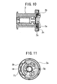
- Fig. 10 is a front view in section, illustrating a state where the take-up drum 2 rotates to a certain degree after the emergency lock mechanism actuates the operation in the assembly illustrated in Fig. 8, and
- Fig. 11 is a partly cutaway side view in the same state.
- the second energy-absorbing means having the above construction is contained in a space delimited between the take-up drum 2 and the locking base 5.
- the emergency lock mechanism actuates the operation, as the take-up drum 2 rotates, the wire 2b illustrated in Fig. 8 and Fig. 9 is wound into the take-up part 2m, as illustrated in Fig. 10 and Fig. 11.
- the wire 2b relatively moves between the disk member 2c and the plate body 2a, along the curved circumference 2i projected from the circumferential face of the disk member 2c, while sliding on the three semi-circular engagement pins 14 of the take-up drum 2.
- the emergency lock mechanism actuates the operation, in case of a vehicle emergency such as a collision, the locking base 5 coupled with the other end of the torsion bar 4 is blocked in rotating in the direction of the webbing pulled out. And, when a rotational torque more than a predetermined value acts on the take-up drum 2, due to the load acting on the webbing, the one end of the torsion bar 4 (first energy-absorbing means) actuates a torsional deformation.
- the take-up drum 2 rotates to a degree corresponding to the torsional deformation in the torsion bar 4, and at the same time, the other end of the torsion bar 4, which is fixed, rotates in the direction of the webbing pulled out, whereby the impact energy is absorbed.
- the actuation of the torsional deformation in the torsion bar 4 generates a relative rotation between the take-up drum 2 and the locking base 5.
- the absorption of the impact energy by the second energy-absorbing means actuates based on this relative rotation.
- the take-up drum 2 rotates relative to the locking base 5
- the plate body 2a to which the one end 2g of the wire 2b is fixed is coupled with the locking base 5, and it does not rotate, while since the engagement pins 14 formed integrally with the take-up drum 2 turn, the wire 2b is pulled between the engagement pins 14. That is, the wire 2b slides between the engagement pins 14 while being positioned by the slopes 2t, while being sequentially pulled to meander between the engagement pins 14.
- there generate a high sliding resistance and a bending resistance in the wire 2b and hence the sliding resistance and the bending resistance absorb the impact energy.
- both the torsion bar 4 (first energy-absorbing means) and the second energy-absorbing means operate as the energy-absorbing mechanism, and absorb the impact energy in case of a vehicle emergency.
- the clutch mechanism releases the engagement of the plate body 2a with the locking base 5 of the emergency lock mechanism, and puts the plate body 2a from the state of a relative rotation with the take-up drum 2 being possible into the state of a united rotation with the take-up drum 2 being possible with the locking base 5 detached.
- This clutch mechanism switches the first state where a relative rotation of the plate body 2a with the other end of the torsion bar 4 is impossible into the second state where a relative rotation of the plate body 2a with the other end of the torsion bar 4 is possible. It also comprises the clutch release mechanism which actuates the switching at an arbitrary timing after detecting a vehicle collision.
- the clutch mechanism comprises, as shown in Fig. 2, a joint plate 5b (Fig. 23) coupled with the emergency lock mechanism in a manner that a relative rotation is impossible, and three joint pawls 12 being pivoted to be turnable on the opposite side of the take-up drum 2 to the plate body 2a, which are in face contact with the joint plate 5b to turn outward.
- the joint pawl 12 (Fig. 15) is a bow-formed member, and a pin 12b is formed on the one end thereof.
- the pin 12b is pivoted on the opposite side of the take-up drum 2 to the plate body 2a.
- the joint pawl 12 turns with the pin 12b as the center.
- the joint pawl 12 has an inner projection 12a (Fig. 15) formed on the center of the inner wall, and a notch 12c (Fig. 15) formed on the other end inside.
- a pawl holder 13 (resin spring) (Fig. 14) in a sectional concave and circular form is provided in order to position and support the joint pawls 12.
- the pawl holder 13 is provided, on the circumference thereof in correspondence with the positions of the joint pawls 12, with nail-formed parts 13c each having ribs 13a formed thereon. Inwardly slant slopes 13b formed on the ribs 13a and the nail-formed parts 13c come into contact with the outer faces of the joint pawls 12. This contact and the resin spring functions to bias the joint pawls 12 continuously toward the axial center.
- the plate body 2a is provided with projections 2s which restrain the joint pawls 12 from turning relative to the plate body 2a immediately after the joint pawls 12 climb over the ribs 13a of the pawl holder 13, the joint pawls 12 are clamped by the rib backsides 13d of the pawl holder and the projections 2s of the plate body so that the joint pawls 12 are prevented from turning to the plate body 2a.
- Fig. 12 is an exploded perspective view explaining the assembling of a release ring 8, the housing 9, a casing 10, and so forth being the components for releasing the clutch.
- Fig. 14 is an enlarged exploded perspective view of the release ring 8, the casing 10, a piston 10a, a gas generator 10b, a gas generator holder 11, and so forth, which are illustrated in Fig. 13.
- the clutch release mechanism will be described with reference to Fig. 12 and Fig. 13.
- the release ring 8 is mounted to be rotatable on the casing 10 fixed to the side plate 9b of the housing on the other side of the torsion bar 4 (Fig. 2), which is located on the circumferences of the joint pawls 12.
- the clutch release mechanism is made up with the casing 10, the gas generator 10b which generates gas in a cylinder 10e at an arbitrary timing after detecting a vehicle collision, and the piston 10a, which is pressed and driven by the gas pressure in the cylinder, and presses the circumference of the release ring 8 to rotate the release ring 8.
- the gas generator 10b is attached to the casing 10 by the gas generator holder 11.
- the release ring 8 is provided with a contact 8b which comes in contact with the piston 10a, and three tapered parts 8a located with a uniform spacing on the circumference thereof.
- the casing 10 which holds the release ring 8 is provided with tapered projections 10d corresponding to the tapered parts 8a of the release ring 8 rotated.
- the piston 10a pressed and driven by the gas pressure comes in contact with the contact 8b formed on the circumference of the release ring 8, and hence the release ring 8 rotates.
- the tapered parts 8a of the release ring 8 are guided by the tapered projections 10d of the casing, and the release ring 8 retreats toward the take-up drum 2 (Fig. 2) and retreats from the circumferences of the joint pawls 12 (Fig. 2).
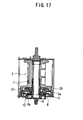
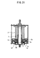
- Fig. 16 through Fig. 21 are partly cutaway side views and plan views in section, which explain the operation of the clutch mechanism.
- the clutch mechanism switches the first state where a relative rotation of the plate body 2a with the other end of the torsion bar 4 is impossible into the second state where a relative rotation of the plate body 2a with the other end of the torsion bar 4 is possible.
- the joint pawls 12 are biased toward the axial center by the slopes 13b (Fig. 14) formed on the ribs 13a of the pawl holder 13.
- the three joint pawls 12 are fixed at the most inwardly convergent position, in non-contact with the inner circumference of the release ring 8, and the inner projections 12a of the joint pawls 12 are in contact with projections 5d of the joint plate 5b.
- an engagement tooth 6b of a lock pawl 6 engages with the lock teeth 9a (Fig. 2) formed on the side plate 9b of the housing, thus generating a relative rotation between the joint plate 5b and the plate body 2a which will continue to rotate.
- a relative rotation is generated between the joint pawls 12 and the projections 5d of the joint plate, whereby the projections 5d of the joint plate press the inner projections 12a of the joint pawls 12, so that the joint pawls 12 receive a force toward the circumference, and they are prone to expand outwardly.
- the joint pawls 12 When the force exceeds the biasing force of the pawl holder 13, the joint pawls 12 come in contact with the inner-circumferential wall of the release ring 8. When the joint pawls 12 come in contact with the inner-circumferential wall of the release ring 8 and the outward expansion thereof is restrained, the locking base 5 and the plate body 2a become integrated with each other, and a relative rotation is generated between the take-up drum 2 and the plate body 2a, so that the wire 2b is pulled and the second energy absorption is performed, in addition to the energy absorption by the torsion bar 4.
- the piston 10a (Fig. 13) operates to rotate the release ring 8, whereby the rotation of the release ring 8 guides the tapered parts 8a of the release ring 8 to the tapered projections 10d of the casing (Fig. 13).
- the release ring 8 retreats toward the take-up drum 2, and retreats from the circumferences of the joint pawls 12 at the same time.
- the joint pawls 12 come in face contact with the joint plate 5b to expand outwardly, and become detached from the projections 5d of the joint plate, whereby the plate body 2a is released from the locking base 5.
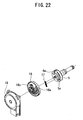
- Fig. 22 is an exploded perspective view explaining the assembling of the emergency lock mechanism, which is made up with the locking base 5, a lock clutch 16, a cover 18, and so forth.
- Fig. 23 is an exploded perspective view explaining the assembling of the torsion bar 4, the lock pawl 6, the locking base 5, and so forth.
- a spring receiving part 16a is formed to project on one side of the lock clutch 16, and the spring receiving part 16a is engaged to be relatively movable with a play inside a spring containing part 5a resembling a recessed-groove shape, which is formed on the locking base 5.
- the spring receiving part 16a is elastically biased in a specified direction by a return spring 17 made of a coil spring retained in the spring containing part 5a, and the lock clutch 16 is made to rotate synchronously with the locking base 5 in a state of being biased in the direction of the webbing pulled out.
- the torsion bar 4 is inserted in a hole bored through the cylindrical boss 5c, which is formed to project from the side of the locking base 5 in the direction of facing the take-up drum 2, whereby, the torsion bar 4 is coupled with the locking base 5 to be rotatable integrally.
- the lock clutch 16 has a projected guide groove 16c formed thereon, and into the guide groove 16c, an interlocking pin 6a formed on the lock pawl 6 (Fig. 23) is slid and guided.
- the interlocking pin 6a is made to be slid and guided into the projected guide groove 16c by a relative rotation of the lock clutch 16 and the locking base 5 against the biasing force by the return spring 17. This sliding and guiding of the interlocking pin 6a makes it possible to freely project or retreat the engagement tooth 6b of the lock pawl 6 from the circumference of the locking base 5.
- the emergency lock mechanism is made up with the locking base 5, the lock pawl 6, the lock teeth 9a (Fig. 2) formed on the housing 9, the lock clutch 16, and so forth.
- a cover 18 is provided with a lock actuating mechanism which actuates the emergency lock mechanism in response to an abrupt pull-out of the webbing and an abrupt variation in the acceleration.
- the locking base 5 and the lock pawl 6 are attached with the joint plate 5b.
- the engagement tooth 6b is formed on a tip of the lock pawl 6, and the lock pawl 6 is located to be slidable on the locking base 5 by the interlocking pin 6a.
- the lock teeth 9a with which the engagement tooth 6b of the lock pawl 6 is able to engage are formed on the side plate 9b of the housing 9, and in case of a vehicle emergency, the engagement tooth 6b of the lock pawl 6 is engaged with the lock teeth 9a, and this engagement restrains the locking base 5 from rotating in the direction of the webbing pulled out.
- the second energy-absorbing means is contained in a space delimited by the take-up drum 2 and the locking base 5, there is not a substantial size expansion in the axial direction of the seatbelt retractor to sacrifice the compactification, although the second energy-absorbing means is provided separately from the torsion bar 4.
- the structures of the wire 2b and the engagement pins 14 which constitute the second energy-absorbing means are equally simple, and the manufacturing process thereof is rather simple as well.
- Fig. 24 is a diagram illustrating the relation between a tensile force acting on the webbing and the amount of the webbing pulled out.
- the whole energy-absorbing load of the seatbelt retractor is the sum f3 of an energy-absorbing load f1 when the torsion bar 4 generates a torsional deformation and an energy-absorbing load f2 by the second energy-absorbing means, as illustrated in Fig. 24.
- the area of the energy absorption by the torsional deformation in the torsion bar 4 can be set freely independently.
- the area of the energy absorption by the second energy-absorbing means can be set to overlap a part of the area of the energy absorption by the torsional deformation in the torsion bar 4, thereby securing a high energy-absorbing load equivalent to the sum of both the energy-absorbing loads, in the part of the area of the energy absorption by the torsional deformation in the torsion bar 4.
- a low energy-absorbing load can be set only by the energy-absorbing function by the torsional deformation in the torsion bar 4.
- the adjustment of the whole energy-absorbing load of the seatbelt retractor is related to various factors such that it is related not only to the modifications of the diameter and material of the torsion bar 4, but also to the modifications of the size, shape, and material of the second energy-absorbing means.
- it is possible to realize a desired energy-absorbing load not depending on the modifications such as expansion of the diameter of the torsion bar 4 and modification of the material thereof, but by means of the design modification of the other remaining factors. That is, it is possible to easily set the energy-absorbing load high, without sacrificing the compactification of the seatbelt retractor by reducing the diameters of the torsion bar 4 and the take-up drum 2.
- both the torsion bar 4 and the second energy-absorbing means can be modified, by adjusting the energy-absorbing load and adjusting the energy-absorbing area in both the means, it becomes possible to easily meet the demand for a specific energy characteristic based on differences of the vehicle structure, and also possible to flexibly meet various needs.
- the adjustment of the sliding resistance between the wire 2b and the engagement pins 14 based on various factors such as a shape of the curved path, roughness of the contact faces of both, and size of the contact area and so forth.
- the adjustment of the sliding resistance is set based on various factors in this manner, for example, if a modification of part of the factors becomes difficult due to the restrictions of the dimensions, modifying the other factors will make it possible to adjust the sliding resistance comparably easily to an arbitrary value required.
- the seatbelt retractor of the invention is provided with the torsion bar 4 and the second energy-absorbing means, and also employs the clutch mechanism. Thereby, it is possible to appropriately select the amount of the energy absorption, by actuating both or only the torsion bar 4 at the actuating time of the energy absorption. And, after actuating the energy absorption by using both, in order to achieve an optimum energy absorption in correspondence with parameters such as physical make-up of vehicle occupant, scale of a vehicle collision, and time, it is possible to stop the provision of load by the second energy-absorbing means on the way, and to perform the energy absorption only by the torsion bar.
- the present invention is useful for a seatbelt retractor which absorbs an impact load acting on a vehicle occupant in case of a vehicle emergency such as a collision, and secures the vehicle occupant.
Landscapes
- Engineering & Computer Science (AREA)
- Mechanical Engineering (AREA)
- Automotive Seat Belt Assembly (AREA)
Claims (7)
- Rétracteur (1) de ceinture de sécurité comprenant :un tambour (2) d'enroulement sur lequel s'enroule la sangle ;un arbre 4) d'enroulement, dont une extrémité est couplée avec une extrémité du tambour d'enroulement d'une manière telle qu'une rotation relative par rapport au tambour d'enroulement est impossible, qui est incliné dans la direction de l'enroulement de la sangle ;un mécanisme (5, 6, 16, 18) de verrouillage d'urgence qui limite une rotation dans la direction de traction sur la sangle ;un mécanisme (5b, 12, 13) d'embrayage situé près de l'autre extrémité de l'arbre d'enroulement ;un corps (2a) de plaque placé près d'un côté sur l'autre extrémité du tambour d'enroulement, qui est placée sur l'autre extrémité de l'arbre d'enroulement par l'intermédiaire du mécanisme d'embrayage ; et un moyen (2e, 2f, 2k, 14) d'absorption d'énergie placé entre le côté du tambour d'enroulement et le corps de plaque, qui apporte une charge résistive par exécution mutuelle d'une rotation relative ;caractérisé en ce que le mécanisme d'embrayage passe d'un premier état, dans lequel le corps de plaque est placé sur l'autre extrémité de l'arbre d'enroulement d'une manière telle qu'une rotation relative par rapport à l'arbre d'enroulement est impossible, à un deuxième état, dans lequel le corps de plaque est placé sur l'autre extrémité de l'arbre d'enroulement d'une manière telle qu'une rotation relative par rapport à l'arbre d'enroulement est possible, et le mécanisme d'embrayage inclut un mécanisme (8, 8a, 8b, 10a, 10b, 10d) de déclenchement de l'embrayage qui actionne un passage à un moment arbitraire.
- Rétracteur (1) de ceinture de sécurité selon la revendication 1, dans lequel
l'arbre (4) d'enroulement est une barre de torsion insérée à travers le tambour (2) d'enroulement ;
le mécanisme de verrouillage d'urgence est placé sur l'autre extrémité de la barre de torsion ; et le rétracteur de ceinture de sécurité comprend en outre un dispositif d'actionnement du verrouillage qui actionne le mécanisme de verrouillage d'urgence dans le cas d'une urgence du véhicule. - Rétracteur (1) de ceinture de sécurité selon la revendication 2, dans lequel le mécanisme d'embrayage inclut :une plaque (5b) de liaison couplée avec le mécanisme de verrouillage d'urgence d'une manière telle qu'une rotation relative par rapport au mécanisme de verrouillage d'urgence est impossible ;au moins un cliquet (12) de liaison pivotant pouvant tourner vers un côté du corps de plaque sur le côté opposé au tambour d'enroulement, qui vient en contact avec la plaque de liaison pour tourner vers l'extérieur ;une bague (8) de déclenchement maintenue par un boîtier fixé sur une plaque latérale d'un carter sur l'autre extrémité de la barre de torsion de manière à être mobile en direction axiale tout en tournant, qui est placée sur une périphérie du cliquet de liaison ; etun mécanisme de déclenchement de l'embrayage qui actionne la bague de déclenchement fixée au boîtier 10).
- Rétracteur (1) de ceinture de sécurité selon la revendication 3, dans lequel le mécanisme de déclenchement de l'embrayage inclut un générateur (10b) de gaz qui génère du gaz dans un cylindre (10e) fixé au boîtier (10) à un moment arbitraire, et un piston (10a) comprimé et entraîné par une pression de gaz dans le cylindre, qui comprime la circonférence de la bague (8) de déclenchement pour faire tourner la bague de déclenchement.
- Rétracteur (1) de ceinture de sécurité selon la revendication 4, dans lequel la bague (8) de déclenchement est munie sur sa circonférence d'un contact (8b) qui vient en contact avec le piston (10a) et de plusieurs éléments coniques (8a) placés avec un espacement uniforme sur sa circonférence, et le boîtier (10) qui maintient la bague de déclenchement est muni de saillies (10d) correspondant aux éléments coniques de la bague de déclenchement.
- Rétracteur (1) de ceinture de sécurité selon l'une quelconque des revendications 1 à 5, dans lequel le mécanisme d'embrayage est muni d'un support (13) de cliquet qui positionne et porte les cliquets (12) de liaison, et le support de cliquet est muni d'épaulements (13a) constitués d'une seule pièce avec lui, qui inclinent les cliquets de liaison dans la direction axiale et ne ramènent pas les cliquets de liaison dans leurs positions initiales après fonctionnement des cliquets de liaison.
- Rétracteur (1) de ceinture de sécurité selon l'une quelconque des revendications 2 à 6, dans lequel le mécanisme d'absorption d'énergie inclut un chemin incurvé (2j) placé sur un côté du tambour (2) d'entraînement sur l'autre extrémité de la barre (4) de torsion, et un fil (2b) dont une extrémité (2g) est fixée sur un élément (2m) d'enroulement du corps (2a) de plaque, dont une partie sensiblement médiane est placée dans la rainure incurvée (2n).
Applications Claiming Priority (3)
| Application Number | Priority Date | Filing Date | Title |
|---|---|---|---|
| JP2003024342 | 2003-01-31 | ||
| JP2003024342A JP4166095B2 (ja) | 2003-01-31 | 2003-01-31 | シートベルトリトラクター |
| PCT/JP2004/000793 WO2004067338A1 (fr) | 2003-01-31 | 2004-01-29 | Retracteur de ceinture de securite |
Publications (3)
| Publication Number | Publication Date |
|---|---|
| EP1600342A1 EP1600342A1 (fr) | 2005-11-30 |
| EP1600342A4 EP1600342A4 (fr) | 2006-02-15 |
| EP1600342B1 true EP1600342B1 (fr) | 2007-03-14 |
Family
ID=32820761
Family Applications (1)
| Application Number | Title | Priority Date | Filing Date |
|---|---|---|---|
| EP04706290A Expired - Fee Related EP1600342B1 (fr) | 2003-01-31 | 2004-01-29 | Retracteur de ceinture de securite |
Country Status (6)
| Country | Link |
|---|---|
| US (1) | US20060214494A1 (fr) |
| EP (1) | EP1600342B1 (fr) |
| JP (1) | JP4166095B2 (fr) |
| KR (1) | KR101105623B1 (fr) |
| DE (1) | DE602004005320T2 (fr) |
| WO (1) | WO2004067338A1 (fr) |
Families Citing this family (12)
| Publication number | Priority date | Publication date | Assignee | Title |
|---|---|---|---|---|
| GB2400351B (en) * | 2003-04-09 | 2006-06-07 | Autoliv Dev | Improvements in or relating to a load limiting arrangement |
| JP5078110B2 (ja) * | 2006-06-15 | 2012-11-21 | タカタ株式会社 | シートベルトリトラクタおよびこれを備えているシートベルト装置 |
| US7497521B2 (en) * | 2006-08-30 | 2009-03-03 | Honda Motor Co., Ltd | Seat belt retractor mounting system |
| JP4885764B2 (ja) * | 2007-02-28 | 2012-02-29 | 株式会社東海理化電機製作所 | ウエビング巻取装置 |
| JP5323223B2 (ja) * | 2012-03-16 | 2013-10-23 | タカタ株式会社 | シートベルトリトラクタおよびこれを備えているシートベルト装置 |
| JP6498506B2 (ja) * | 2015-04-24 | 2019-04-10 | 株式会社東海理化電機製作所 | ウェビング巻取装置 |
| JP6306537B2 (ja) * | 2015-05-29 | 2018-04-04 | 株式会社東海理化電機製作所 | ウェビング巻取装置 |
| CN107791998B (zh) * | 2017-12-08 | 2024-02-20 | 沈阳金杯锦恒汽车安全系统有限公司 | 一种安全带卷收器芯轴组件结构 |
| US10434976B2 (en) | 2018-02-27 | 2019-10-08 | Ford Global Technologies, Llc | Seatbelt assembly |
| US10518740B2 (en) | 2018-02-27 | 2019-12-31 | Ford Global Technologies, Llc | Seatbelt assembly |
| US10543806B2 (en) | 2018-02-27 | 2020-01-28 | Ford Global Technologies, Llc | Seatbelt assembly |
| US10525929B2 (en) | 2018-02-27 | 2020-01-07 | Ford Global Technologies, Llc | Seatbelt assembly |
Family Cites Families (25)
| Publication number | Priority date | Publication date | Assignee | Title |
|---|---|---|---|---|
| DE1935539C2 (de) * | 1969-07-12 | 1984-10-25 | Adam Opel AG, 6090 Rüsselsheim | Kraftbegrenzer für Sicherheitsgurte |
| JPS5619245U (fr) * | 1979-07-19 | 1981-02-20 | ||
| US5607118A (en) * | 1995-08-11 | 1997-03-04 | Alliedsignal Inc. | Retractor with adjustable load limiting levels |
| JP3709231B2 (ja) * | 1996-01-24 | 2005-10-26 | 株式会社東海理化電機製作所 | ウエビング巻取装置 |
| JPH09286302A (ja) * | 1996-04-23 | 1997-11-04 | Nippon Seiko Kk | シートベルト用リトラクター |
| BR9709962A (pt) * | 1996-06-26 | 1999-08-10 | Autoliv Dev | Dispositivo enrolador de cinta com dispositivo de limitação de força ajustável |
| US5823570A (en) * | 1996-10-10 | 1998-10-20 | Trw Vehicle Safety Systems Inc. | Seat belt retractor with energy management |
| DE19733787C1 (de) * | 1997-08-05 | 1998-12-03 | Daimler Benz Ag | Gurtroller für ein Sicherheitsgurtsystem eines Personensitzes |
| DE29718663U1 (de) * | 1997-10-21 | 1998-02-19 | Trw Repa Gmbh | Kraftbegrenzter in einem Sicherheitsgurt-Rückhaltesystem |
| PL333492A1 (en) * | 1998-06-04 | 1999-12-06 | Trw Repa Gmbh | Force-limiting sub-assembly for a safety-belt winding mechanism and safety-belt winding mechanism incorporating same |
| DE29816280U1 (de) * | 1998-09-10 | 1999-01-21 | Trw Repa Gmbh | Vorrichtung zur Kraftbegrenzung |
| DE29821801U1 (de) * | 1998-12-07 | 1999-04-08 | Trw Repa Gmbh | Gurtaufroller für einen Fahrzeug-Sicherheitsgurt |
| DE19856364A1 (de) * | 1998-12-07 | 2000-06-08 | Trw Repa Gmbh | Gurtaufroller für einen Fahrzeugsicherheitsgurt |
| DE19927427C2 (de) * | 1999-06-16 | 2002-11-14 | Autoliv Dev | Gurtaufroller mit schaltbarem Kraftbegrenzer |
| JP4526631B2 (ja) * | 2000-01-24 | 2010-08-18 | オートリブ株式会社 | シートベルト装置 |
| JP2001287621A (ja) * | 2000-04-07 | 2001-10-16 | Tokai Rika Co Ltd | ウェビング巻取装置 |
| JP2001301569A (ja) * | 2000-04-24 | 2001-10-31 | Tokai Rika Co Ltd | ウェビング巻取装置及び車両 |
| JP2001347921A (ja) * | 2000-05-02 | 2001-12-18 | Takata Corp | シートベルトリトラクタ |
| JP3723423B2 (ja) * | 2000-05-31 | 2005-12-07 | エヌエスケー・オートリブ株式会社 | シートベルト装置 |
| JP4323081B2 (ja) * | 2000-10-26 | 2009-09-02 | 株式会社東海理化電機製作所 | ウエビング巻取装置 |
| JP4721387B2 (ja) * | 2000-12-08 | 2011-07-13 | タカタ株式会社 | シートベルトリトラクタ |
| GB2387576B (en) * | 2002-04-16 | 2004-04-14 | Breed Automotive Tech | Retractor |
| GB2387574B (en) * | 2002-04-16 | 2004-05-19 | Breed Automotive Tech | Retractor |
| DE20210812U1 (de) * | 2002-07-17 | 2002-11-21 | Trw Repa Gmbh | Gurtaufroller mit Kraftbegrenzungsfunktion |
| US6969022B2 (en) * | 2003-10-14 | 2005-11-29 | Key Safety Systems, Inc. | Seat belt retractor |
-
2003
- 2003-01-31 JP JP2003024342A patent/JP4166095B2/ja not_active Expired - Fee Related
-
2004
- 2004-01-29 KR KR1020057013386A patent/KR101105623B1/ko active IP Right Grant
- 2004-01-29 DE DE602004005320T patent/DE602004005320T2/de not_active Expired - Lifetime
- 2004-01-29 EP EP04706290A patent/EP1600342B1/fr not_active Expired - Fee Related
- 2004-01-29 US US10/543,893 patent/US20060214494A1/en not_active Abandoned
- 2004-01-29 WO PCT/JP2004/000793 patent/WO2004067338A1/fr active IP Right Grant
Also Published As
| Publication number | Publication date |
|---|---|
| US20060214494A1 (en) | 2006-09-28 |
| DE602004005320D1 (de) | 2007-04-26 |
| KR20050091092A (ko) | 2005-09-14 |
| JP4166095B2 (ja) | 2008-10-15 |
| DE602004005320T2 (de) | 2007-12-20 |
| KR101105623B1 (ko) | 2012-01-18 |
| EP1600342A1 (fr) | 2005-11-30 |
| WO2004067338A1 (fr) | 2004-08-12 |
| JP2004262262A (ja) | 2004-09-24 |
| EP1600342A4 (fr) | 2006-02-15 |
Similar Documents
| Publication | Publication Date | Title |
|---|---|---|
| US7942361B2 (en) | Webbing retracting device | |
| EP1600342B1 (fr) | Retracteur de ceinture de securite | |
| EP1738975B1 (fr) | Retracteur de ceinture de securite | |
| JP4976241B2 (ja) | シートベルトリトラクタおよびこれを用いたシートベルト装置 | |
| JP3306050B2 (ja) | シートベルト用リトラクタのガス発生装置一体型プリテンショナ | |
| JP4917395B2 (ja) | ウエビング巻取装置 | |
| JP5511076B2 (ja) | シートベルトリトラクタおよびこれを備えるシートベルト装置 | |
| JP2009061809A (ja) | シートベルトリトラクタおよびこれを用いたシートベルト装置 | |
| JP2008213526A (ja) | シートベルトリトラクタおよびこれを用いたシートベルト装置 | |
| US20110057066A1 (en) | Seatbelt retractor | |
| US20080203807A1 (en) | Seat belt retractor and seat belt apparatus employing the same | |
| US9205773B2 (en) | Webbing take-up device | |
| KR100620620B1 (ko) | 좌석 벨트용 리트렉터의 프리텐셔너 | |
| WO2013179978A1 (fr) | Enrouleur automatique pour ceinture de sécurité | |
| US20160059824A1 (en) | Seatbelt retractor | |
| JP2002145012A (ja) | シートベルトリトラクタ | |
| JP2013049401A (ja) | ウェビング巻取装置 | |
| WO2023112614A1 (fr) | Dispositif d'enroulement de sangle | |
| JP2006159982A (ja) | シートベルト用リトラクター | |
| KR200366953Y1 (ko) | 좌석 벨트용 리트렉터의 프리텐셔너 | |
| JP6739358B2 (ja) | ウェビング巻取装置 | |
| JP2016137757A (ja) | ウェビング巻取装置 |
Legal Events
| Date | Code | Title | Description |
|---|---|---|---|
| PUAI | Public reference made under article 153(3) epc to a published international application that has entered the european phase |
Free format text: ORIGINAL CODE: 0009012 |
|
| 17P | Request for examination filed |
Effective date: 20050825 |
|
| AK | Designated contracting states |
Kind code of ref document: A1 Designated state(s): AT BE BG CH CY CZ DE DK EE ES FI FR GB GR HU IE IT LI LU MC NL PT RO SE SI SK TR |
|
| AX | Request for extension of the european patent |
Extension state: AL LT LV MK |
|
| A4 | Supplementary search report drawn up and despatched |
Effective date: 20060102 |
|
| DAX | Request for extension of the european patent (deleted) | ||
| RBV | Designated contracting states (corrected) |
Designated state(s): DE FR GB |
|
| GRAP | Despatch of communication of intention to grant a patent |
Free format text: ORIGINAL CODE: EPIDOSNIGR1 |
|
| RIN1 | Information on inventor provided before grant (corrected) |
Inventor name: KATAYAMA, TAKAO |
|
| GRAS | Grant fee paid |
Free format text: ORIGINAL CODE: EPIDOSNIGR3 |
|
| GRAA | (expected) grant |
Free format text: ORIGINAL CODE: 0009210 |
|
| AK | Designated contracting states |
Kind code of ref document: B1 Designated state(s): DE FR GB |
|
| REG | Reference to a national code |
Ref country code: GB Ref legal event code: FG4D |
|
| REF | Corresponds to: |
Ref document number: 602004005320 Country of ref document: DE Date of ref document: 20070426 Kind code of ref document: P |
|
| ET | Fr: translation filed | ||
| PLBE | No opposition filed within time limit |
Free format text: ORIGINAL CODE: 0009261 |
|
| STAA | Information on the status of an ep patent application or granted ep patent |
Free format text: STATUS: NO OPPOSITION FILED WITHIN TIME LIMIT |
|
| 26N | No opposition filed |
Effective date: 20071217 |
|
| PGFP | Annual fee paid to national office [announced via postgrant information from national office to epo] |
Ref country code: FR Payment date: 20120202 Year of fee payment: 9 |
|
| PGFP | Annual fee paid to national office [announced via postgrant information from national office to epo] |
Ref country code: GB Payment date: 20120125 Year of fee payment: 9 |
|
| GBPC | Gb: european patent ceased through non-payment of renewal fee |
Effective date: 20130129 |
|
| REG | Reference to a national code |
Ref country code: FR Ref legal event code: ST Effective date: 20130930 |
|
| PG25 | Lapsed in a contracting state [announced via postgrant information from national office to epo] |
Ref country code: GB Free format text: LAPSE BECAUSE OF NON-PAYMENT OF DUE FEES Effective date: 20130129 Ref country code: FR Free format text: LAPSE BECAUSE OF NON-PAYMENT OF DUE FEES Effective date: 20130131 |
|
| PGFP | Annual fee paid to national office [announced via postgrant information from national office to epo] |
Ref country code: DE Payment date: 20140122 Year of fee payment: 11 |
|
| REG | Reference to a national code |
Ref country code: DE Ref legal event code: R119 Ref document number: 602004005320 Country of ref document: DE |
|
| PG25 | Lapsed in a contracting state [announced via postgrant information from national office to epo] |
Ref country code: DE Free format text: LAPSE BECAUSE OF NON-PAYMENT OF DUE FEES Effective date: 20150801 |