EP1599404B1 - Folding machine for folding a continuous web material and folding method - Google Patents
Folding machine for folding a continuous web material and folding method Download PDFInfo
- Publication number
- EP1599404B1 EP1599404B1 EP04709319A EP04709319A EP1599404B1 EP 1599404 B1 EP1599404 B1 EP 1599404B1 EP 04709319 A EP04709319 A EP 04709319A EP 04709319 A EP04709319 A EP 04709319A EP 1599404 B1 EP1599404 B1 EP 1599404B1
- Authority
- EP
- European Patent Office
- Prior art keywords
- folding
- web material
- gripping member
- suction
- roller
- Prior art date
- Legal status (The legal status is an assumption and is not a legal conclusion. Google has not performed a legal analysis and makes no representation as to the accuracy of the status listed.)
- Expired - Lifetime
Links
- 238000000034 method Methods 0.000 title claims description 15
- 230000000694 effects Effects 0.000 claims description 6
- 238000007789 sealing Methods 0.000 claims description 4
- 230000001360 synchronised effect Effects 0.000 claims description 4
- 230000015572 biosynthetic process Effects 0.000 claims description 2
- 230000003213 activating effect Effects 0.000 claims 1
- 230000000284 resting effect Effects 0.000 claims 1
- 238000011144 upstream manufacturing Methods 0.000 claims 1
- 230000010355 oscillation Effects 0.000 description 9
- 230000008878 coupling Effects 0.000 description 4
- 238000010168 coupling process Methods 0.000 description 4
- 238000005859 coupling reaction Methods 0.000 description 4
- 230000004323 axial length Effects 0.000 description 1
- 230000006835 compression Effects 0.000 description 1
- 238000007906 compression Methods 0.000 description 1
- 230000001419 dependent effect Effects 0.000 description 1
- 238000003780 insertion Methods 0.000 description 1
- 230000037431 insertion Effects 0.000 description 1
- 238000012423 maintenance Methods 0.000 description 1
- 238000004519 manufacturing process Methods 0.000 description 1
Images


Classifications
-
- B—PERFORMING OPERATIONS; TRANSPORTING
- B65—CONVEYING; PACKING; STORING; HANDLING THIN OR FILAMENTARY MATERIAL
- B65H—HANDLING THIN OR FILAMENTARY MATERIAL, e.g. SHEETS, WEBS, CABLES
- B65H45/00—Folding thin material
- B65H45/02—Folding limp material without application of pressure to define or form crease lines
- B65H45/06—Folding webs
- B65H45/10—Folding webs transversely
-
- B—PERFORMING OPERATIONS; TRANSPORTING
- B65—CONVEYING; PACKING; STORING; HANDLING THIN OR FILAMENTARY MATERIAL
- B65H—HANDLING THIN OR FILAMENTARY MATERIAL, e.g. SHEETS, WEBS, CABLES
- B65H45/00—Folding thin material
- B65H45/12—Folding articles or webs with application of pressure to define or form crease lines
- B65H45/20—Zig-zag folders
-
- B—PERFORMING OPERATIONS; TRANSPORTING
- B65—CONVEYING; PACKING; STORING; HANDLING THIN OR FILAMENTARY MATERIAL
- B65H—HANDLING THIN OR FILAMENTARY MATERIAL, e.g. SHEETS, WEBS, CABLES
- B65H45/00—Folding thin material
- B65H45/02—Folding limp material without application of pressure to define or form crease lines
- B65H45/06—Folding webs
-
- B—PERFORMING OPERATIONS; TRANSPORTING
- B65—CONVEYING; PACKING; STORING; HANDLING THIN OR FILAMENTARY MATERIAL
- B65H—HANDLING THIN OR FILAMENTARY MATERIAL, e.g. SHEETS, WEBS, CABLES
- B65H45/00—Folding thin material
- B65H45/12—Folding articles or webs with application of pressure to define or form crease lines
- B65H45/16—Rotary folders
- B65H45/162—Rotary folders with folding jaw cylinders
- B65H45/164—Details of folding blades therefor
-
- B—PERFORMING OPERATIONS; TRANSPORTING
- B65—CONVEYING; PACKING; STORING; HANDLING THIN OR FILAMENTARY MATERIAL
- B65H—HANDLING THIN OR FILAMENTARY MATERIAL, e.g. SHEETS, WEBS, CABLES
- B65H2406/00—Means using fluid
- B65H2406/30—Suction means
- B65H2406/35—Other elements with suction surface, e.g. plate or wall
- B65H2406/351—Other elements with suction surface, e.g. plate or wall facing the surface of the handled material
Definitions
- the present invention relates to a folding machine to fold a web material along transverse folding lines. More specifically, the invention relates to a folding machine of the type comprising a pair of counter-rotating folding rollers, placed side by side and with axes parallel, each of which has at least a gripping member to grasp the web material along transverse lines and make folds along said lines.
- the invention also relates to a means to folding a continuous web material according to transverse zigzag lines.
- a continuous web material - which may be previously folded according to a longitudinal line - is fed to a pair of counter-rotating folding rollers, arranged with parallel axes and side by side with each other to define a nip through which the web material is fed.
- Disposed on each roller are members that make the fold in the web material.
- the aforesaid members are disposed and controlled so that the web material is folded in zigzags, adhering alternately first to one and then to the other of the two counter-rotating folding rollers.
- the pack formed of the web material folded in a zigzag is then cut by a blade and divided into two rows of paper napkins or similar folded products.
- a machine of this type is described for example in WO-A-9728076 and in WO-A-0162651.
- Other examples of folding machines are described in US patent 3.195.882, in US patent 3.229.974, in US patent 3.820.774, in US patent 3.689.061, in German patent 446.753 and in German patent 429.288.
- the folding members of these folding machines include on each folding roller a gripping member which with each turn of the roller grips the web material along a folding line.
- respective folding blades or wedges are located on the two folding rollers, in positions angularly staggered with respect to the gripping members.
- a folding blade of one of the two folding rollers and a gripping member of the other folding roller are in angular positions so that they come to correspond with each other in the nip defined between the two folding rollers, and the web material is pushed by the folding blade inside the gripping member.
- each of the two folding rollers has at least one folding blade and one gripping member, so that for each complete turn of the pair of folding rollers at least two folds are made on the web material.
- folding blades and gripping members on the counter-rotating folding rollers makes these machines particularly complex from a mechanical viewpoint. Moreover, the mechanical action of the folding blade or wedge on the web material tends to damage it. The folding blades are subject to rapid wear with consequent maintenance costs.
- the object of the present invention is to produce a folding machine of the aforesaid type, which is simpler, but at the same time efficient and reliable.
- a folding machine comprising in combination: at least one folding roller with at least one mechanical gripping member to grasp the web material; associated with said at least one gripping member, a gaseous flow member, such as an air flow member to insert the web material towards said gripping member.
- the gas or air flow member includes a suction member to pull the web material towards or into said gripping member.
- the gas or air flow member includes an air ejection member, to generate a flow of compressed air to push the web material towards or in said gripping member.
- two counter-rotating folding rollers may be arranged side by side, each provided with one or more gripping members.
- the web material is inserted into the gripping member by the effect of suction, without requiring to provide a folding blade on the opposed folding roller.
- the suction effect is less likely to damage the web material with respect to the mechanical action of usual folding blades, in particular when extremely soft or embossed products are processed, which are easily marked by the action of mechanical members.
- each of the suction members is associated with a device to activate and deactivate suction as a function of the angular position of the respective folding roller, the suction member of each folding roller being active for a fraction of a complete turn of the respective folding roller.
- Each of the gripping members can include a movable element cooperating with a first stop, said suction member using suction to position the web material between said movable element and said stop.
- suitable devices can be provided to limit the effect of suction to the desired zone.
- each of the folding rollers can be provided with at least one cavity essentially parallel to its axis of rotation and open on the cylindrical surface of the folding roller, inside which the respective gripping member is housed, with a suction duct, which is part of the respective suction member, terminating in said cavity.
- each of said cavities are advantageously provided with means to limit the effect of suction on one side of the movable element, between it and said first stop.
- a first block defining the first stop with which the respective movable element cooperates can, for example, be fixed in each cavity.
- This first block delimits a suction compartment in connection with the suction duct and is provided with a plurality of suction holes distributed along the longitudinal extension of said first block and terminating on a surface of said block positioned on the opposite side with respect to said suction compartment and facing the movable element.
- This surface may be specifically shaped to form a sealing surface cooperating with an oscillating shaft forming part of the movable element.
- the holes are in this case disposed between the first stop defined by said block and said sealing surface.
- each of said folding rollers may advantageously be associated with a sliding block with a connecting channel between said suction line and a suction duct in the respective folding roller.
- This sliding block rests on a sliding surface provided on the folding roller, typically and advantageously on one of the two faces of the roller and in particular preferably the upper surface.
- the sliding block may advantageously be resiliently pushed against said sliding surface produced on the respective roller. It may have an elongated aperture communicating with the respective folding roller.
- the devices to activate and deactivate suction can be adjustable, to adjust the opening and closing position of suction as a function of the angular position of the respective folding roller.
- this sliding block can be designed so that it is disposed in a specific angular position adjustable in respect of the relative folding roller, so as to adjust the positions in which suction starts and stops.
- an air ejection member is used to push the web material towards the gripping member, said air ejection member can be arranged on the surface of one folding roller or of a roller parallel and adjacent to a folding roller, in a position phased with the position of the gripping member on the opposed folding roller, such that the air ejection member passes in front of the gripping member in correspondence of the nip formed between the folding rollers while the rollers rotate.
- a gripping member and an air ejection member, arranged in diametrically opposed positions, can be provided on each folding roller when the machine includes two parallel and adjacent folding rollers.
- the invention relates to a method for folding a web material according to transverse folding lines, comprising the steps of:
- the web material is inserted into the respective gripping members by an air flow, such as by suction.
- two folding rollers may be provided, placed side by side and provided with gripping members that grip the web material alternately, to fold it in a zigzag.
- the folding machine has a pair of folding rollers 1 and 3 rotating around respective vertical axes of rotation 1A and 3A, arranged parallel to each other and at a distance such that the two folding rollers 1, 3 are placed side by side at a nip 5.
- the folding roller 1 is supported by means of tangs 1C and 1D in corresponding supports 7, 9.
- the folding roller 3 is supported analogously by tangs 3C and 3D in supports 11 and 13.
- the two folding rollers 1 and 3 are carried in rotation in opposed directions (arrows f1 and f3 in Figures 5 and 6) by means of a toothed wheel 14 that meshes with a toothed wheel 15 keyed onto the shaft of the folding roller 1, and which in turn meshes with a toothed wheel keyed onto the shaft of the folding roller 3.
- the rocker arm 23 is keyed onto a vertical shaft 25, parallel to the axes of two folding rollers 1, 3 and carries integral with it a shaped plate 26 that is inserted into an annular groove 27 in the folding roller 1.
- longitudinal seats or cavities are produced inside the two folding rollers 1, 3.
- the two cavities are symmetrical with each other as can be seen in particular in Figure 5 and the folding rollers are synchronized with each other so that the cavities are in diametrally opposite positions.
- the cavities 41 terminate on the cylindrical surface of each of the two folding rollers 1, 3.
- a gripping member indicated as a whole with 43 which is used to grip and fold the web material N fed into the nip 5 between the two folding rollers 1, 3.
- the two gripping members 43 are symmetrical with each other and only one of them will be described in detail hereunder.
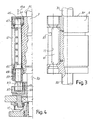
- the gripping member includes, as can be seen in particular in Figure 4, a shaft with an oscillation axis 45A parallel to the axis of rotation of the respective folding roller.
- the shaft 45 is supported by bearings 47 and 49 housed in the respective folding roller.
- the shaft is provided with an oscillating movement around its axis, controlled by means of a cam 51 which has a channel 53 inside which a wheel or feeler 55 engages, keyed onto a spindle 57 connected by means of a bracket 59 to the shaft 45 (see in particular Figure 4).
- the cam 51 which is fixed in respect of the machine structure, controls oscillation of the wheel 55 and of the respective spindle 57 around the axis of oscillation 45A of the shaft 45, which will consequently be carried in rotation in turn.
- a strip 61 is integral with the shaft 45, fastened to said shaft 45 by means of screws 62.
- the strip 61 extends radially until reaching approximately the cylindrical surface of the respective folding roller 1 or 3.
- the cam with the channel 51 makes the shaft 45 oscillate around its axis
- the strip 61 oscillates between two positions defined by two stops formed by a first block indicated as a whole with 63 and by a second block indicated as a whole with 65.
- the two blocks 63, 65 are housed in the seat or cavity 41 of the respective folding roller.
- the first block 63 shown in greater detail in Figures 9 to 11 and described hereunder, is fixed to the respective folding roller by means of screws 67, while the block 65 is fixed to the roller by means of screws 69.
- the blocks 63 and 65 extend longitudinally, parallel to the axis of the respective folding roller, for approximately its entire height and therefore involve the entire axial extension of the cavity 41.
- the block 65 has a longitudinal groove 71 housed inside which is a rectilinear gasket 73 with a circular cross section, which forms an elastic stop for the strip 61.
- the block 63 has a cylindrical surface 63A which, when the block is mounted in the respective folding roller, is flush with the cylindrical surface of the folding roller.
- This cylindrical surface is interrupted by a groove 63B, at the annular groove 37 or 27 of the folding roller 3 or 1.
- a stop surface 63C is formed along one of the edges delimiting the cylindrical surface 63A of the block 63 ; when the block is mounted in the respective folding roller, this surface is positioned in front of the gasket 73 of the block 65.
- the block 63 On the same side of the stop surface 63C, the block 63 has a second cylindrical surface 63D the curvature radius of which is essentially equivalent to the curvature radius of the cylindrical surface of the shaft 45.
- the shaft 45 practically grazes the cylindrical surface 63D of the block 63 for the purposes to be clarified hereunder.
- the block 63 also has a plurality of through holes 63E that allow the two opposed faces of the block to communicate: the face on which the cylindrical surface 63D is produced and the back face on which a flat part 63F is produced.
- the flat part 63F faces an elongated aperture 77 (see in particular Figure 3) communicating with a suction member comprising a suction duct 79 produced in the body of the respective folding roller and terminating on the upper flat surface thereof. Therefore, a suction compartment 78 is defined between the flat part 63F and the suction duct 79.
- suction ducts 79 of the two folding rollers 1, 3 are connected (in the way to be described in detail hereunder with reference to Figures 7 and 12) to suction means that produce a vacuum in a part of the cavity 41 of the respective folding roller for the purposes described hereunder.
- the suction duct 79 communicates with the surface of the block 63 facing the strip 61 through the through holes 63E. With this arrangement, by means of the suction duct 79 (when a vacuum is formed in it) a vacuum is created in the volume delimited by the strip 61 with the relative support, by the shaft 45 and by the face of the block 63 facing the strip 61. This volume is indicated with V in Figure 5.
- a connecting arrangement is provided cooperating with the upper front or base surface of each of the two rollers, indicated with 1F for the folding roller 1 and with 3F for the folding roller 3. This arrangement is shown in detail in Figure 7 for the folding roller 3.
- the folding roller 1 has a symmetrical arrangement.
- a sliding block 81 also rests on said front surface, by means of a plate 83 in a material with a low coefficient of friction.
- the sliding block 81 is slidingly engaged to two guide columns 85 blocked vertically in respective couplings 87. These couplings are in turn fixed to a flange 89 attached to a portion 91 of the fixed structure of the machine.
- Two compression springs 93 (one of which can be seen in Figure 7), stress the sliding block 81 against the front surface of the respective folding roller 1 or 3.
- the flange 89 is shown in a plan view in Figure 8.
- the number 95 indicates two threesomes of holes of the fixing screws 97 of the retaining couplings 87 for the guide columns 85.
- the flange 89 is provided with two curved slots 99. Two screws (one of which is indicated with 101 in Figure 7) are inserted in these to fix the flange 89 to the machine structure 91. Thanks to the curved slots 99, by loosening the screws 101 it is possible to adjust the angular position of each flange 89 with respect to the axis of the relative folding roller 1 or 3. In this way the angular position of the respective sliding block 81 can be adjusted.
- the structure of the sliding block 81 is shown in detail in Figures 6 and 12. It has a main body in which a lowered seat 103 is made, inside which the plate 83 is housed.
- the main body and the plate 83 of the sliding block 81 have a hole with an oblong section 105, which extends parallel to the axis of the folding rollers 1 and 3.
- the oblong hole 105 is joined to a lateral hole 107 connected to a suction tube 109 in turn connected to a fan or another suitable suction member, not shown.
- the folding machine described hereinbefore operates in the following way.
- the two folding rollers 1 and 3 rotate in opposed directions as represented by the arrows f1 and f3, while the web material N (which may already be folded according to a continuous longitudinal folding line), is fed into the nip 5 between the two folding rollers.
- the gripping members housed in the two cavities 41 of the two folding rollers 1 and 3 are disposed in synchronized angular positions so that when the gripping member of the folding roller 3 is at the nip 5, the gripping member associated with the folding roller 1 is in a position diametrally opposite with respect to the nip between the rollers.
- the two angular positions shown in Figures 13A and 13C are those in which suction starts and stops through the suction duct 79 associated with the folding roller 3.
- the angular position in Figure 13B is intermediate between the two suction start and stop positions and corresponds to the position in which the gripping member associated with the folding roller 3 is in the nip 5 between the two folding rollers.
- the cam 51 causes oscillation of the shaft 45 associated with said folding roller, making it rotate clockwise so that the elastic strip 61 pinches the web material, which has wedged in the slit defined by the strip 61 and by the stop 63C as a result of suction, against the stop 63C
- the mechanical restraint produced on the web material by the elastic strip 61 and by the stop 63C causes it to fold along a transverse line.
- suction through the duct 79 associated with the folding roller 3 is interrupted and the web material is held on the surface of the folding roller 3 purely as a result of mechanical restraint.
- the oscillating plate 35 associated with the folding roller 3 is in its withdrawn position inside the groove 37 of the roller. Consequently, the folded web material N is carried over the curved portion of said plate.
- the strip 61 is opened as a result of clockwise oscillation of the shaft 45 and the portion of folded web material is detached from the folding roller 3 by means of controlled oscillation of the plate 35.
- This operation to detach the web material folded by the folding roller is per se known and analogous to that of known machines.
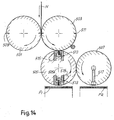
- Figure 14 shows a folding machine wherein the web material is cut into sheets prior to transverse folding.
- the machine schematically is provided with a cutting unit composed of two counter-rotating cylinders with parallel axes 501, 503. A nip is defined between these cylinders, through which the web material is fed, which may be folded longitudinally prior to transverse cutting and folding.
- the numbers 509 and 511 indicate pairs of blades and counter-blades carried by the two cylinders 501, 503.
- the web material N cut into single sheets is held on the surface of the cylinder 503 by suction holes, not shown, and the individual sheets are thereby made to enter a nip defined by the cylinder 503 and by a folding roller 505.
- this has a pair of mechanical gripping members 513 that may be produced analogously to the mechanical gripping members of the previous embodiment.
- the number 515 schematically indicates suction members that can in practice be produced in the same way as those described with reference to the previous figures and which have the same function of using suction to make a portion of the individual sheets of web material N enter the gripping member.
- the folding roller 505 which rotates around its axis 505A, forms a nip with a distributor roller 507 that has suction holes and that is used to divide the flow of folded sheets so that they are distributed (in a way known per se) into two rows F1, F2 upon delivery from the nip between the rollers 505 and 507.
- suction system according to the invention utilized to insert a loop of web material into the gripping member to make the fold facilitates production of a machine wherein the fold is performed on the web material previously divided into portions or sheets.
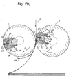
- Figures 15A and 15B show, in two consecutive moments during rotation of the folding rollers, a plan view and partial section of the folding rollers in an improved embodiment of the invention.
- Equivalent numbers indicated equivalent or corresponding parts to those in the previous Figures 1 to 13.
- the embodiment in Figures 15A, 15B differs from the previous one for the different configuration of the volume V wherein suction is produced. In this case suction on the web material to be folded is exerted directly through the through holes 63E produced in the block 63 and terminating on the surface of said block against which the strip 61 nips the folded material.
- each folding roller 1, 3 in a position diametrally opposite with respect to the seat in which the folding strip 61 is housed, of an element that facilitates start of suction of the material to be folded between the strip 61 and the block 63.
- This element is constituted by an insert 201 fixed in a notch of the respective roller 1 or 3, extending parallel to the axis of rotation of the roller.
- the number 203 indicates fixing screws.
- the insert 201 is divided into two portions, separated by the groove 27 or 37 of the respective roller.
- the insert 201 has a ribbing or projection 201A that projects slightly (for a few tens of millimeter, typically 0.1-0.5 mm) from the cylindrical side surface of the respective folding roller 1, 3.
- the two rollers 1, 3 are synchronized so that the projection 201A is carried in front of the suction compartment between the strip 61 and the block 63 of the opposed roller.
- the projection 201A is located in front of the suction compartment and makes the web material N to be folded, when it rests on said projection, project towards the opposed roller (roller 3 in the position shown). This facilitates pick-up of the material by suction.
- FIG 15B the subsequent position is shown, in which the projection 201A (as a result of rotation of the folding roller 1) moves away from the strip 61.
- Said strip has not yet pinched the web material N, which has been engaged by suction and forms a loop between the block 63 and the strip 61. Therefore, contrary to the method used by known folding machines, wherein the web material is pinched by a strip acting against an insertion wedge to obtain the fold, in the configuration shown herein there is no mechanical cooperation between the blade 61 and the projection 201A, that is the web material is not gripped or pinched between strip 61 and projection 201A.
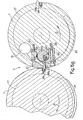
- the operating principle is clearly shown in the sequence in Figures 16A, 16B, 16C which show the two folding rollers in three consecutive angular positions while making the fold in the web material N.
- the insert 201 with the projection 201A facilitates pick-up by suction of the web material by the suction device and allows even greater operating speeds to be attained.
- the solution can also be adopted in the configurations of the folding rollers shown in the previous figures. In the configuration with only one folding roller in Figure 14, the insert 20 can be fitted on the cylinder 503.
- FIGs. 17A and 17B show yet a further embodiment of the invention. Similar or corresponding elements are designated with the same reference numbers as in the previous figures.
- Each folding roller 1, 3 has a cavity 41 into which a strip 61 is oscillatingly housed.
- the strip 61 is supported by an oscillating shaft 45 and forms part of the gripping member designated 43 as a whole.
- the strip 61 is designed to grip or grasp the web material and fold it by pinching between the strip 61 and a fixed abutment 62 extending along the opening of the seat or cavity 41 on the surface of the respective roller.
- each folding roller 1, 3 is provided with a linear air nozzle 601 extending parallel to the axis of the folding roller and for approximately its entire axial length.
- a linear air nozzle 601 a line of individual nozzles can be provided.
- the nozzle is housed in a longitudinal notch in the cylindrical surface of the folding roller.
- the nozzle projects slightly, e.g. 0.1-0.5 mm, from the roller surface.
- the position of the air nozzles 601 and of the gripping members on the two rollers 1, 3 is such that during rotation of the rollers 1, 3 a nozzle 601 of one roller faces a gripping member of the opposed roller in the nip 5 between the rollers to generate a fold in the web material N.
- the nozzle 601 starts to generate an air jet, e.g. by means of compressed air coming from a line of compressed air from a fan or a compressor.
- Flow connection between the fan and the nozzle 601 can be designed similar to the flow connection described above with respect to the previous embodiments.
- the air flow generated by the nozzle 601 pushes the web material N towards and into the gripping member, between the abutment 62 and the strip 61.
- a loop of web material is thus formed inside the cavity 41, between abutment 62 and strip 61.
- the strip 61 is oscillated to pinch the ioop of web material N between the strip 61 and the abutment 62, thus forming the fold.
- the web material is introduced into the gripping member without mechanical action.
- the slight projection of the nozzle 601 from the surface of the roller facilitates the formation of the loop, without mechanical contact between the nozzle and the gripping member.
- the nozzle 601 can be connected to a fan or an air compressor through a compressed air line, similarly to what has been disclosed before with reference to the suction system and the suction line. Phasing of the air jet can also be obtained in a way similar to the one disclosed above for synchronizing the suction effect.
- the strip 61 is designed with an abutment near to its distal edge, i.e. to the edge which is farther away from the oscillation axis.
- This abutment provides a limitation to the dimension of the loop formed by the air flow, i.e. a limitation to the amount of web introduced into the gripping member.
- the abutment could be formed by the roller rather than by the strip 61.
- a similar arrangement can be provided also in the previously described embodiments, to limit the amount of web material sucked into the folding roller.
Applications Claiming Priority (3)
| Application Number | Priority Date | Filing Date | Title |
|---|---|---|---|
| ITFI20030037 | 2003-02-12 | ||
| IT000037A ITFI20030037A1 (it) | 2003-02-12 | 2003-02-12 | Macchina piegatrice per la produzione di manufatti in foglio, |
| PCT/IT2004/000050 WO2004071921A1 (en) | 2003-02-12 | 2004-02-09 | Folding machine for folding a continuous web material and folding method |
Publications (2)
| Publication Number | Publication Date |
|---|---|
| EP1599404A1 EP1599404A1 (en) | 2005-11-30 |
| EP1599404B1 true EP1599404B1 (en) | 2007-04-25 |
Family
ID=32866047
Family Applications (1)
| Application Number | Title | Priority Date | Filing Date |
|---|---|---|---|
| EP04709319A Expired - Lifetime EP1599404B1 (en) | 2003-02-12 | 2004-02-09 | Folding machine for folding a continuous web material and folding method |
Country Status (12)
| Country | Link |
|---|---|
| US (1) | US20050159286A1 (pt) |
| EP (1) | EP1599404B1 (pt) |
| JP (1) | JP4210683B2 (pt) |
| KR (1) | KR101295944B1 (pt) |
| CN (1) | CN100360388C (pt) |
| AT (1) | ATE360593T1 (pt) |
| BR (1) | BRPI0403941B1 (pt) |
| CA (1) | CA2483900A1 (pt) |
| DE (1) | DE602004006090T2 (pt) |
| ES (1) | ES2285426T3 (pt) |
| IT (1) | ITFI20030037A1 (pt) |
| WO (1) | WO2004071921A1 (pt) |
Cited By (2)
| Publication number | Priority date | Publication date | Assignee | Title |
|---|---|---|---|---|
| CN102241162A (zh) * | 2011-07-12 | 2011-11-16 | 常德烟草机械有限责任公司 | 一种手帕纸折叠机的小折叠吸辊装置 |
| US11834211B2 (en) | 2019-09-19 | 2023-12-05 | Korber Tissue S.p.A. | Packing machine for paper product converting line and method for packing of paper products |
Families Citing this family (12)
| Publication number | Priority date | Publication date | Assignee | Title |
|---|---|---|---|---|
| ITFI20040030A1 (it) * | 2004-02-11 | 2004-05-10 | Perini Fabio Spa | Macchina piegatrice per piegare un materiale continuo e relativo metodo di piegatura |
| US9079744B2 (en) * | 2009-08-26 | 2015-07-14 | Horizon International Inc. | Sheet folding apparatus |
| EP2627594B1 (de) * | 2010-10-15 | 2015-05-13 | Winkler + Dünnebier GmbH | Vorrichtung und verfahren zum querfalten eines bahnabschnitts und hygienetuch |
| DE102016004897A1 (de) | 2015-12-04 | 2017-06-08 | Serv-O-Tec Druck- Und Papierverarbeitungsmaschinen Gmbh | Querfalzverfahren und Vorrichtung für Produktbahnen und Produktbahnabschnitte |
| IT201600077916A1 (it) | 2016-07-25 | 2018-01-25 | Universal Tissue Tech S R L | Rullo piegatore e macchina interfogliatrice impiegante detto rullo |
| CN106364969A (zh) * | 2016-08-26 | 2017-02-01 | 芜湖悠派护理用品科技股份有限公司 | 一种宠物尿垫折叠机构 |
| ES2925915T3 (es) | 2018-04-27 | 2022-10-20 | Koerber Tissue S P A | Rodillo de plegado y máquina que comprende dicho rodillo |
| IT201900012561A1 (it) | 2019-07-22 | 2021-01-22 | Mtc Macch Trasformazione Carta S R L | Macchina per la produzione di pacchi di prodotti di carta e relativo metodo di produzione |
| IT201900017048A1 (it) * | 2019-09-23 | 2021-03-23 | Mtc Macch Trasformazione Carta S R L | Struttura perfezionata di macchina interfogliatrice |
| CN111362039B (zh) * | 2020-06-01 | 2020-08-07 | 常州利贞电子科技有限公司 | 一种长宽自定义的标签印刷折叠输送机 |
| IT202100010283A1 (it) * | 2021-04-22 | 2022-10-22 | Koerber Tissue Fold S R L | Unita’ di piega, o interfogliatura, di fogli di carta in una macchina per la trasformazione della carta |
| IT202100011531A1 (it) * | 2021-05-06 | 2022-11-06 | Koerber Tissue Fold S R L | Unita’ di piega, o interfogliatura, di fogli di carta in una macchina per la trasformazione della carta |
Family Cites Families (29)
| Publication number | Priority date | Publication date | Assignee | Title |
|---|---|---|---|---|
| US843781A (en) * | 1904-12-31 | 1907-02-12 | Seth Wheeler | Apparatus for cutting, folding, and interfolding sheets or units. |
| US1358665A (en) * | 1919-10-07 | 1920-11-09 | Max M Cohn | Interfolding-machine |
| US2872186A (en) * | 1956-07-10 | 1959-02-03 | Levey Fred K H Co Inc | Folder for printing presses |
| US3195882A (en) * | 1963-08-27 | 1965-07-20 | Paper Converting Machine Co | Rotary zigzag folding apparatus |
| US3229974A (en) * | 1963-11-13 | 1966-01-18 | Kimberly Clark Co | Paper folding machine |
| US3346253A (en) * | 1965-03-31 | 1967-10-10 | Frank R Paschke | Electrostatic sheet control means |
| US3323794A (en) * | 1965-04-05 | 1967-06-06 | Harris Intertype Corp | Sheet handling apparatus |
| US3689061A (en) * | 1970-07-02 | 1972-09-05 | Paper Converting Machine Co | System for folding napkins |
| US3918698A (en) * | 1970-11-23 | 1975-11-11 | Coast Machinery Inc | High speed machine and method for folding plastic bags and the like |
| US3773315A (en) * | 1971-06-04 | 1973-11-20 | Exxon Research Engineering Co | Sheet and bag folder |
| US3820774A (en) * | 1972-06-29 | 1974-06-28 | Polygraph Kom Veb | Folding blade cylinder for use in rotary folding machines |
| US3870292A (en) * | 1973-03-16 | 1975-03-11 | Paper Converting Machine Co | Method and apparatus for transverse folding of webs |
| US3991994A (en) * | 1973-11-05 | 1976-11-16 | Wood Industries, Inc. | Zig-zag web folder apparatus |
| US4095780A (en) * | 1976-10-07 | 1978-06-20 | Harris Corporation | Retracting tucker blade and brush for cylinder folder |
| DE2745359A1 (de) * | 1977-10-08 | 1979-04-19 | Koenig & Bauer Ag | Falzklappenzylinder fuer einen falzapparat in rollenrotationsdruckmaschinen |
| US4487598A (en) * | 1978-03-30 | 1984-12-11 | Union Carbide Corporation | Bag folding apparatus |
| DE2909006A1 (de) * | 1979-03-08 | 1980-09-11 | Winkler Duennebier Kg Masch | Falzvorrichtung zum erzeugen einer zickzackfoermigen bahn aus papier, zellstoff, tissue o.dgl. werkstoff |
| DE2931968B1 (de) * | 1979-08-07 | 1981-07-16 | Heidelberger Druckmaschinen Ag, 6900 Heidelberg | Falzapparat an Rollen-Rotationsdruckmaschinen |
| US4494949A (en) * | 1983-01-10 | 1985-01-22 | The Lehigh Press, Inc. | Sheet folding apparatus and method |
| US4521209A (en) * | 1983-04-22 | 1985-06-04 | Paper Converting Machine Company | Apparatus and method for transverse folding of webs |
| JPH0266067A (ja) * | 1988-08-31 | 1990-03-06 | Taiyo Plant Kk | ポリエチレン袋折りたたみ装置 |
| EP0612879B1 (de) * | 1993-02-18 | 1995-02-08 | Jensen Ag Burgdorf | Falteinrichtung zum automatischen Falten von Wäschestücken |
| DE4419989C2 (de) * | 1994-06-08 | 1997-10-02 | Winkler Duennebier Kg Masch | Verfahren und Vorrichtung zum Stapeln von gefalteten Tüchern |
| DE69702429T2 (de) * | 1996-10-15 | 2000-11-09 | Komori Printing Mach | Falzapparat ohne Punkturnadeln |
| DE19716628C2 (de) * | 1997-04-21 | 2000-11-23 | Koenig & Bauer Ag | Verfahren und Vorrichtung zum Querfalzen von Signaturen |
| EP0982255B1 (en) * | 1998-08-21 | 2006-12-20 | M T C - Macchine Trasformazione Carta S.r.l. | Interfolding method of sheet material and machine for carrying out such method |
| WO2001062654A1 (fr) * | 2000-02-22 | 2001-08-30 | Mitsubishi Denki Kabushiki Kaisha | Dispositif elevateur |
| IT1314574B1 (it) | 2000-02-23 | 2002-12-20 | Perini Fabio Spa | Dispositivo di piegatura per materiale in foglio, macchina per laproduzione di manufatti in foglio e metodo di piegatura impiegante |
| DE10043517A1 (de) * | 2000-09-01 | 2002-03-14 | Winkler & Duennebier Ag | Verfahren und Vorrichtung zum formatabhängigen Einrichten von mindestens einem Werkzeug auf einem Werkzeugträger |
-
2003
- 2003-02-12 IT IT000037A patent/ITFI20030037A1/it unknown
-
2004
- 2004-02-09 JP JP2005501716A patent/JP4210683B2/ja not_active Expired - Fee Related
- 2004-02-09 KR KR1020047016273A patent/KR101295944B1/ko active IP Right Grant
- 2004-02-09 WO PCT/IT2004/000050 patent/WO2004071921A1/en active IP Right Grant
- 2004-02-09 AT AT04709319T patent/ATE360593T1/de not_active IP Right Cessation
- 2004-02-09 US US10/510,570 patent/US20050159286A1/en not_active Abandoned
- 2004-02-09 CN CNB2004800001460A patent/CN100360388C/zh not_active Expired - Fee Related
- 2004-02-09 BR BRPI0403941A patent/BRPI0403941B1/pt not_active IP Right Cessation
- 2004-02-09 CA CA002483900A patent/CA2483900A1/en not_active Abandoned
- 2004-02-09 ES ES04709319T patent/ES2285426T3/es not_active Expired - Lifetime
- 2004-02-09 EP EP04709319A patent/EP1599404B1/en not_active Expired - Lifetime
- 2004-02-09 DE DE602004006090T patent/DE602004006090T2/de not_active Expired - Lifetime
Cited By (2)
| Publication number | Priority date | Publication date | Assignee | Title |
|---|---|---|---|---|
| CN102241162A (zh) * | 2011-07-12 | 2011-11-16 | 常德烟草机械有限责任公司 | 一种手帕纸折叠机的小折叠吸辊装置 |
| US11834211B2 (en) | 2019-09-19 | 2023-12-05 | Korber Tissue S.p.A. | Packing machine for paper product converting line and method for packing of paper products |
Also Published As
| Publication number | Publication date |
|---|---|
| EP1599404A1 (en) | 2005-11-30 |
| DE602004006090D1 (de) | 2007-06-06 |
| CN1697770A (zh) | 2005-11-16 |
| ATE360593T1 (de) | 2007-05-15 |
| JP4210683B2 (ja) | 2009-01-21 |
| BRPI0403941A (pt) | 2005-03-01 |
| WO2004071921A1 (en) | 2004-08-26 |
| US20050159286A1 (en) | 2005-07-21 |
| ES2285426T3 (es) | 2007-11-16 |
| JP2006508880A (ja) | 2006-03-16 |
| DE602004006090T2 (de) | 2007-12-27 |
| ITFI20030037A1 (it) | 2004-08-13 |
| BRPI0403941B1 (pt) | 2015-12-29 |
| KR101295944B1 (ko) | 2013-08-13 |
| CN100360388C (zh) | 2008-01-09 |
| KR20050103869A (ko) | 2005-11-01 |
| CA2483900A1 (en) | 2004-08-26 |
Similar Documents
| Publication | Publication Date | Title |
|---|---|---|
| EP1599404B1 (en) | Folding machine for folding a continuous web material and folding method | |
| US5147273A (en) | Method and apparatus for producing stacks of interleaved material sheets | |
| EP0199285B1 (en) | Web winding machine and method | |
| US4917665A (en) | Bedroll interfolding machinery improvement | |
| US4778441A (en) | Interfolding machinery improvement | |
| US5405126A (en) | Format-variable combination folder | |
| US5004451A (en) | Folding apparatus with improved web transport | |
| CA2086954C (en) | Device for extracting samples from a folder | |
| JPH0712880B2 (ja) | ウエブ折込方法およびその装置 | |
| EP1814812B1 (en) | Rewinding machine for the production of logs of web material and logs obtained | |
| US4930383A (en) | Combination cutting and path switching apparatus for moving webs, particularly printed paper substrates, and method | |
| GB2223745A (en) | Interfolding sheets | |
| TWI553189B (zh) | 吸輥系統及材料捲處理設備 | |
| EP1713710B1 (en) | Folding machine for folding a continuous web material and relative folding method | |
| EP1776304B1 (en) | Folding machine with suction means for zig-zag folding a continuous web material and associated folding method | |
| US11208292B2 (en) | Folding roller and machine comprising said roller | |
| EP3067303B1 (en) | Apparatus and method for forming sheets of different lengths or sheets with different panel lengths, and processing roll for handling sheets | |
| EP3781506B1 (en) | Suction roller structure for interfolding machines | |
| EP0852214B1 (en) | Method and device for feeding sheet material | |
| GB965217A (en) | Improved gripper mechanisms for interleaving machines |
Legal Events
| Date | Code | Title | Description |
|---|---|---|---|
| PUAI | Public reference made under article 153(3) epc to a published international application that has entered the european phase |
Free format text: ORIGINAL CODE: 0009012 |
|
| 17P | Request for examination filed |
Effective date: 20041002 |
|
| AK | Designated contracting states |
Kind code of ref document: A1 Designated state(s): AT BE BG CH CY CZ DE DK EE ES FI FR GB GR HU IE IT LI LU MC NL PT RO SE SI SK TR |
|
| AX | Request for extension of the european patent |
Extension state: AL LT LV MK |
|
| DAX | Request for extension of the european patent (deleted) | ||
| GRAP | Despatch of communication of intention to grant a patent |
Free format text: ORIGINAL CODE: EPIDOSNIGR1 |
|
| GRAS | Grant fee paid |
Free format text: ORIGINAL CODE: EPIDOSNIGR3 |
|
| GRAA | (expected) grant |
Free format text: ORIGINAL CODE: 0009210 |
|
| AK | Designated contracting states |
Kind code of ref document: B1 Designated state(s): AT BE BG CH CY CZ DE DK EE ES FI FR GB GR HU IE IT LI LU MC NL PT RO SE SI SK TR |
|
| PG25 | Lapsed in a contracting state [announced via postgrant information from national office to epo] |
Ref country code: CH Free format text: LAPSE BECAUSE OF FAILURE TO SUBMIT A TRANSLATION OF THE DESCRIPTION OR TO PAY THE FEE WITHIN THE PRESCRIBED TIME-LIMIT Effective date: 20070425 Ref country code: LI Free format text: LAPSE BECAUSE OF FAILURE TO SUBMIT A TRANSLATION OF THE DESCRIPTION OR TO PAY THE FEE WITHIN THE PRESCRIBED TIME-LIMIT Effective date: 20070425 Ref country code: FI Free format text: LAPSE BECAUSE OF FAILURE TO SUBMIT A TRANSLATION OF THE DESCRIPTION OR TO PAY THE FEE WITHIN THE PRESCRIBED TIME-LIMIT Effective date: 20070425 |
|
| REG | Reference to a national code |
Ref country code: GB Ref legal event code: FG4D |
|
| REG | Reference to a national code |
Ref country code: IE Ref legal event code: FG4D |
|
| REG | Reference to a national code |
Ref country code: CH Ref legal event code: EP |
|
| REF | Corresponds to: |
Ref document number: 602004006090 Country of ref document: DE Date of ref document: 20070606 Kind code of ref document: P |
|
| PG25 | Lapsed in a contracting state [announced via postgrant information from national office to epo] |
Ref country code: SE Free format text: LAPSE BECAUSE OF FAILURE TO SUBMIT A TRANSLATION OF THE DESCRIPTION OR TO PAY THE FEE WITHIN THE PRESCRIBED TIME-LIMIT Effective date: 20070725 |
|
| ET | Fr: translation filed | ||
| PG25 | Lapsed in a contracting state [announced via postgrant information from national office to epo] |
Ref country code: PT Free format text: LAPSE BECAUSE OF FAILURE TO SUBMIT A TRANSLATION OF THE DESCRIPTION OR TO PAY THE FEE WITHIN THE PRESCRIBED TIME-LIMIT Effective date: 20070925 |
|
| REG | Reference to a national code |
Ref country code: CH Ref legal event code: PL |
|
| NLV1 | Nl: lapsed or annulled due to failure to fulfill the requirements of art. 29p and 29m of the patents act | ||
| REG | Reference to a national code |
Ref country code: ES Ref legal event code: FG2A Ref document number: 2285426 Country of ref document: ES Kind code of ref document: T3 |
|
| PG25 | Lapsed in a contracting state [announced via postgrant information from national office to epo] |
Ref country code: AT Free format text: LAPSE BECAUSE OF FAILURE TO SUBMIT A TRANSLATION OF THE DESCRIPTION OR TO PAY THE FEE WITHIN THE PRESCRIBED TIME-LIMIT Effective date: 20070425 |
|
| PG25 | Lapsed in a contracting state [announced via postgrant information from national office to epo] |
Ref country code: BE Free format text: LAPSE BECAUSE OF FAILURE TO SUBMIT A TRANSLATION OF THE DESCRIPTION OR TO PAY THE FEE WITHIN THE PRESCRIBED TIME-LIMIT Effective date: 20070425 |
|
| PG25 | Lapsed in a contracting state [announced via postgrant information from national office to epo] |
Ref country code: NL Free format text: LAPSE BECAUSE OF FAILURE TO SUBMIT A TRANSLATION OF THE DESCRIPTION OR TO PAY THE FEE WITHIN THE PRESCRIBED TIME-LIMIT Effective date: 20070425 Ref country code: BG Free format text: LAPSE BECAUSE OF FAILURE TO SUBMIT A TRANSLATION OF THE DESCRIPTION OR TO PAY THE FEE WITHIN THE PRESCRIBED TIME-LIMIT Effective date: 20070725 Ref country code: DK Free format text: LAPSE BECAUSE OF FAILURE TO SUBMIT A TRANSLATION OF THE DESCRIPTION OR TO PAY THE FEE WITHIN THE PRESCRIBED TIME-LIMIT Effective date: 20070425 Ref country code: SI Free format text: LAPSE BECAUSE OF FAILURE TO SUBMIT A TRANSLATION OF THE DESCRIPTION OR TO PAY THE FEE WITHIN THE PRESCRIBED TIME-LIMIT Effective date: 20070425 Ref country code: CZ Free format text: LAPSE BECAUSE OF FAILURE TO SUBMIT A TRANSLATION OF THE DESCRIPTION OR TO PAY THE FEE WITHIN THE PRESCRIBED TIME-LIMIT Effective date: 20070425 |
|
| PG25 | Lapsed in a contracting state [announced via postgrant information from national office to epo] |
Ref country code: SK Free format text: LAPSE BECAUSE OF FAILURE TO SUBMIT A TRANSLATION OF THE DESCRIPTION OR TO PAY THE FEE WITHIN THE PRESCRIBED TIME-LIMIT Effective date: 20070425 |
|
| PLBE | No opposition filed within time limit |
Free format text: ORIGINAL CODE: 0009261 |
|
| STAA | Information on the status of an ep patent application or granted ep patent |
Free format text: STATUS: NO OPPOSITION FILED WITHIN TIME LIMIT |
|
| 26N | No opposition filed |
Effective date: 20080128 |
|
| PG25 | Lapsed in a contracting state [announced via postgrant information from national office to epo] |
Ref country code: GR Free format text: LAPSE BECAUSE OF FAILURE TO SUBMIT A TRANSLATION OF THE DESCRIPTION OR TO PAY THE FEE WITHIN THE PRESCRIBED TIME-LIMIT Effective date: 20070726 |
|
| PGFP | Annual fee paid to national office [announced via postgrant information from national office to epo] |
Ref country code: ES Payment date: 20080121 Year of fee payment: 5 |
|
| PG25 | Lapsed in a contracting state [announced via postgrant information from national office to epo] |
Ref country code: RO Free format text: LAPSE BECAUSE OF FAILURE TO SUBMIT A TRANSLATION OF THE DESCRIPTION OR TO PAY THE FEE WITHIN THE PRESCRIBED TIME-LIMIT Effective date: 20070425 |
|
| PG25 | Lapsed in a contracting state [announced via postgrant information from national office to epo] |
Ref country code: MC Free format text: LAPSE BECAUSE OF NON-PAYMENT OF DUE FEES Effective date: 20080228 |
|
| PG25 | Lapsed in a contracting state [announced via postgrant information from national office to epo] |
Ref country code: EE Free format text: LAPSE BECAUSE OF FAILURE TO SUBMIT A TRANSLATION OF THE DESCRIPTION OR TO PAY THE FEE WITHIN THE PRESCRIBED TIME-LIMIT Effective date: 20070425 Ref country code: IE Free format text: LAPSE BECAUSE OF NON-PAYMENT OF DUE FEES Effective date: 20080211 |
|
| PG25 | Lapsed in a contracting state [announced via postgrant information from national office to epo] |
Ref country code: CY Free format text: LAPSE BECAUSE OF FAILURE TO SUBMIT A TRANSLATION OF THE DESCRIPTION OR TO PAY THE FEE WITHIN THE PRESCRIBED TIME-LIMIT Effective date: 20070425 |
|
| REG | Reference to a national code |
Ref country code: ES Ref legal event code: FD2A Effective date: 20090210 |
|
| PG25 | Lapsed in a contracting state [announced via postgrant information from national office to epo] |
Ref country code: HU Free format text: LAPSE BECAUSE OF FAILURE TO SUBMIT A TRANSLATION OF THE DESCRIPTION OR TO PAY THE FEE WITHIN THE PRESCRIBED TIME-LIMIT Effective date: 20071026 Ref country code: ES Free format text: LAPSE BECAUSE OF NON-PAYMENT OF DUE FEES Effective date: 20090210 Ref country code: LU Free format text: LAPSE BECAUSE OF NON-PAYMENT OF DUE FEES Effective date: 20080209 |
|
| PG25 | Lapsed in a contracting state [announced via postgrant information from national office to epo] |
Ref country code: TR Free format text: LAPSE BECAUSE OF FAILURE TO SUBMIT A TRANSLATION OF THE DESCRIPTION OR TO PAY THE FEE WITHIN THE PRESCRIBED TIME-LIMIT Effective date: 20070425 |
|
| REG | Reference to a national code |
Ref country code: FR Ref legal event code: PLFP Year of fee payment: 13 |
|
| REG | Reference to a national code |
Ref country code: FR Ref legal event code: PLFP Year of fee payment: 14 |
|
| REG | Reference to a national code |
Ref country code: FR Ref legal event code: PLFP Year of fee payment: 15 |
|
| REG | Reference to a national code |
Ref country code: FR Ref legal event code: PLFP Year of fee payment: 17 |
|
| PGFP | Annual fee paid to national office [announced via postgrant information from national office to epo] |
Ref country code: GB Payment date: 20200226 Year of fee payment: 17 |
|
| PGFP | Annual fee paid to national office [announced via postgrant information from national office to epo] |
Ref country code: FR Payment date: 20200225 Year of fee payment: 17 |
|
| PGFP | Annual fee paid to national office [announced via postgrant information from national office to epo] |
Ref country code: DE Payment date: 20200429 Year of fee payment: 17 |
|
| REG | Reference to a national code |
Ref country code: DE Ref legal event code: R119 Ref document number: 602004006090 Country of ref document: DE |
|
| GBPC | Gb: european patent ceased through non-payment of renewal fee |
Effective date: 20210209 |
|
| PG25 | Lapsed in a contracting state [announced via postgrant information from national office to epo] |
Ref country code: GB Free format text: LAPSE BECAUSE OF NON-PAYMENT OF DUE FEES Effective date: 20210209 Ref country code: FR Free format text: LAPSE BECAUSE OF NON-PAYMENT OF DUE FEES Effective date: 20210228 Ref country code: DE Free format text: LAPSE BECAUSE OF NON-PAYMENT OF DUE FEES Effective date: 20210901 |
|
| PGFP | Annual fee paid to national office [announced via postgrant information from national office to epo] |
Ref country code: IT Payment date: 20220221 Year of fee payment: 19 |
|
| P01 | Opt-out of the competence of the unified patent court (upc) registered |
Effective date: 20230530 |
|
| PG25 | Lapsed in a contracting state [announced via postgrant information from national office to epo] |
Ref country code: IT Free format text: LAPSE BECAUSE OF NON-PAYMENT OF DUE FEES Effective date: 20230209 |