EP1598462A1 - Kettfadenwächter für Webmaschine - Google Patents
Kettfadenwächter für Webmaschine Download PDFInfo
- Publication number
- EP1598462A1 EP1598462A1 EP04011910A EP04011910A EP1598462A1 EP 1598462 A1 EP1598462 A1 EP 1598462A1 EP 04011910 A EP04011910 A EP 04011910A EP 04011910 A EP04011910 A EP 04011910A EP 1598462 A1 EP1598462 A1 EP 1598462A1
- Authority
- EP
- European Patent Office
- Prior art keywords
- warp
- contact
- stopper according
- contact rails
- rails
- Prior art date
- Legal status (The legal status is an assumption and is not a legal conclusion. Google has not performed a legal analysis and makes no representation as to the accuracy of the status listed.)
- Granted
Links
Images


Classifications
-
- D—TEXTILES; PAPER
- D03—WEAVING
- D03D—WOVEN FABRICS; METHODS OF WEAVING; LOOMS
- D03D51/00—Driving, starting, or stopping arrangements; Automatic stop motions
- D03D51/18—Automatic stop motions
- D03D51/20—Warp stop motions
- D03D51/28—Warp stop motions electrical
- D03D51/30—Warp stop motions electrical wherein droppers are suspended on individual warp threads or small groups of threads
Definitions
- the invention relates to a warp stop motion for a Weaving machine for detecting warp thread breaks.
- Such a warp stop motion is for example from the WO 88/00626 known.
- He has one or more contact rails on, above the warp thread plane transverse to Kettfadenlaufraum are arranged horizontally.
- Each contact rail has a narrow upright cross-section, on the upper edge of which is a longitudinal slot, in which another contact rail is kept isolated.
- On the Contact rail sit next to each other many individual slats.
- the contact rail extends through elongated, in the blades formed windows.
- the slats are made of Steel and are with game vertically up and down on the contact rail movable. Give in their raised position they have no electrical connection between the top recessed Rail and the contact rail.
- Each lamella points an eye or other opening, through which each one a warp thread extends. Is the warp thread taut At the same time he keeps the lamella in upper position, so that this can not make electrical contact. If the warp thread falls, the lamella falls under the effect of her Dead weight down and connects the two contact rails with each other, what an evaluation circuit is detected and leads to shutdown of the loom.
- Warp stopper for incorrect shutdowns. Such mistakes come especially in weaving machines, in which the Warp threads, related to their direction, in a against the Run horizontal inclined plane to the shedding apparatus. Especially pronounced erroneous attitudes occur when e.g. in the production of synthetic technical fabrics working with high yarn tensions. Will with the thread a Hochfach formed, the thread tension is usually less than when forming a Tieffachs. At the transition from the low depth, e.g. via the middle compartment to the high compartment it comes to the voltage change, whereby the thread briefly can sag something. How far the thread sags, is determined by the slat weight. Thus, the slats moves up and down during the change of subject.
- Warp stop motion to create a diminished tendency for misconduct shows and also for use at an angle Warp threads is suitable.
- the warp stopper according to the invention has lamellentragende Contact rails on which at least one damping element are mounted on the machine frame.
- the warp stopper according to the invention is particularly suitable for slope use, i. with the loom with Slope or slope to running warp threads and for production technical fabric, where due to the special Shed geometry to increased thread tension variations can come.
- the reduced number of false shutdowns The overall result is a significantly improved Fabric quality and thus to an improved recyclable Yield or production.
- the contact rails can be above or below the Be arranged warp threads.
- the contact rails preferably have an elongated cross section, whose Longitudinal direction is perpendicular to the warp threads.
- Warp thread level are the contact rails thus against the vertical inclined.
- the slats lie in one acute angle to the vertical. They therefore tend to with a flank of her window to the side of the Contact rail to create. The reduced tendency to vibration
- the contact rails leads here to a reduced friction between lamella and contact rail.
- the contact rails are at their ends and possibly also one or more places between them Ends stored on a carrier.
- the damping element is arranged between the carrier and the Machine frame.
- the Contact rails and the carrier can thus be used as ground and the damping element acting as a spring, so that a spring mass system is formed.
- the damping element is for example spring-elastic design. It can also be a have inner damping to the vibration transmission to minimize.
- Rubber element used. This has the further advantage due to its low sound propagation speed to form a barrier to structure-borne sound. The speed of sound is about 70 times less in rubber than in Steel, so that over the machine frame incoming shock waves reflected by the rubber element, but not to the Contact rails are given further.
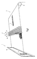
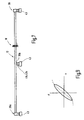
- FIG. 1 schematically shows parts of a weaving machine to which a shedding device 1, a Warp stopper 2 and a Kettfadenunter listening 3 belong.
- the shed forming device 1 comprises a plurality of healds, of which a heald 10 is illustrated, as well as the associated, not shown drive device.
- FIG. 2 illustrates in side view how two adjacent, only by dotted lines 4, 5 indicated weaving shafts work in opposite directions. Every weave carries, as illustrated in Figure 1, a number of strands 6 through the eyelets of the warp threads 7 run.
- the Warp threads come from a warp beam, which is the warp thread feeder forms.
- the warp stop motion 2 has several, juxtaposed flat contact rails 12 to 17, the upright standing parallel to each other next to each other are arranged. They span all warp threads 7 in the transverse direction. How out Figure 2 seen, their lower edges lie on a common Plane E, which is arranged parallel to the warp thread plane 9 is. The same applies to their upper edges.
- the Flanks of the contact rails 12 are perpendicular to the Warp thread level 9 as well as oriented to the plane E.
- the warp thread plane is shown 9 and the plane E at an acute angle to the horizontal H arranged.
- This configuration is especially in modern weaving machines for making synthetic Tissue.
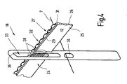
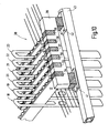
- the contact rails 12 to 17 are equal to each other built up. They are all with slats 18, 19, 20, 21, 22, 23 equipped, which, as shown in Figure 3, on the Contact rails 12, 13, 14, 15, 16, 17 sit. Each contact rail 12 to 17 carries a variety of fins, wherein in Figure 3 on each contact rail 12 to 17 only a lamella 18 to 23 exemplified is. The slats 18 to 23 are constructed equal to each other. Likewise, the contact rails 12 to 17 with each other built up the same. For explanation, reference is made to FIG. 4, in the contact rail 12 and the blade 18th are illustrated on behalf of everyone else.
- the contact rail 12 is a narrow upright standing U-profile 24 made of steel or another mechanically stable and electrically conductive material. It has two to each other substantially parallel flat sides 25, 26 (contact surfaces) on, in a direction transverse to the warp threads 7 and oriented in the other direction at right angles to these are. Between the flat sides 25, 26 bearing Legs is provided a recess in which a further rail 27 (contact surface) electrically isolated is held.
- the rail 27 is a flat, electrical Ladder, by a U-shaped insulator 28 of the Contact rail 12 is insulated.
- the rail 27 projects beyond the two upper edges 29, 31, on which the flat sides 25, 26th end up.
- the insulator 28 protrudes here from the interior of the Contact rail out.
- the even further up Rail 27 is preferably at its upper edge with a Tooth profile 32 provided.
- the lamella 18 is approximately rectangular in outline Sheet metal part with an upper window 33 through which the Contact rail 12 extends therethrough.
- the window 33 is in Vertical direction much longer than in the same direction measured height of the contact rail 12.
- the width of the Window 33 is slightly larger than the thickness of the contact rail 12, so that the slat 18 with some play easily can move up and down.
- the window is at its top Edge slightly bevelled to be sure an electric Contact the rail 27 and the contact rail 12 forth lead when the lamella is released and by its weight falls down.
- the essentially strained warp 7 carries the blade 18, e.g. in the position illustrated in Figure 4, in which its upper Bridge 35 at a considerable distance above the rail 27th stands.
- the warp thread 7a If a warp thread breaks, as shown in FIG. 11, the warp thread 7a, he can no longer wear the associated blade 18a. These thus falls down under the effect of its own weight their second position, in which they have the rail 27 and the contact rail 12 electrically bridged.
- the rail 27 and the Contact rail 12 are via lines 36, 37 to a not further illustrated control circuit connected to the established electrical contact between the rail 27 and the contact rail 12 detects and appropriate measures takes, for example, the loom off.
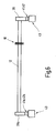
- FIG. 5 illustrates, the contact rails 12 to 17 at least end to a holding device 38th held.
- a carrier 39 which with all contact rails 12 to 17 is connected.
- the carrier 39 is in Figure 5 indicated only schematically. He holds the contact rails 12 to 17 stationary in parallel alignment to each other and parallel to the warp thread plane.
- the carrier 39 is via damping elements 41, 42 with a machine frame 43 associated with the weaving machine.
- the damping elements 41, 42 are in the simplest case one or more layers constructed rubber elements. In the preferred case no metallic rigid connection between the machine frame 43 and the carrier 39.
- the damping elements 41, 42 are for example rubber plates. advantageously, they are multi-layered. For example, they can as illustrated in FIG.
- one foot plate 44 in each case one foot plate 44, a first foot plate mounted, e.g. vulcanized Rubber plate 45, one made of metal, e.g. a thin sheet, existing intermediate plate 46, an overlying another Rubber plate 47 and an upper, made of metal end plate 48 have.
- This multi-layer construction can be linked by vulcanization. He points preferably at least in one direction approximately square cross section on.
- the damping elements 41, 42 be constructed in total cuboid. By their rectangular Base area they can be a preferred direction regarding obtained the spring action. In the illustrated orientation ( Figure 5) spring the damper elements 41, 42 based on the Lengthwise of the contact rails 12 to 17 lighter than referenced on the Kettfadenlnaturesraum. In many cases however, it may be advantageous, the damper elements 41, 42 to 90 ° to the storage with respect to the longitudinal direction the contact rails 12 to 17 stiff and with respect to the Make the transverse direction soft.
- the contact rail 12 is held at each of its two ends to supports 39, 39a, which in turn via the damping elements 41, 42 and 41 a, 42 a are held on the machine frame 43.
- the contact rails 12 to 17 extra long as for example is illustrated in Figure 7, they can also be centered or be additionally supported in other places.
- the damping elements 41, 42, 41a, 42a, 41b, 42b can made of an elastomer, a natural rubber, a synthetic one Rubber or a mixture of both. It are relatively hard rubber compounds with high internal damping prefers.
- FIG. 9 exemplarily illustrates the force-displacement characteristic of such a rubber spring element, which in dynamic Load encloses an area. The size of the Surface is a measure of the energy absorption of the damping element.
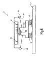
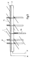
- FIG. 8 illustrates another embodiment of the warp stop 2.
- the carrier 39 carries next to the contact rails 12 to 17 optionally still support rails 49, 51 for supporting the warp threads in front of and behind the contact rails 12 to 17.
- the carrier 39 is otherwise adjustable, for example, one parallel to the contact rails 12 to 17 oriented pivot axis pivotally mounted. For this purpose, it has a pin 52 which is in a clamping block 53 is held.
- the clamping block 53 is above the damping elements 41, 42 connected to the machine frame 43.
- FIG. 10 illustrates a modified embodiment the damped holding device 38.
- the damping elements 41, 42 for connection between the machine frame 43 and the carrier 39.
- the contact rails 12 to 17 at their ends via buffer or damping elements 54 to 59 held on the carrier 39.
- damping elements 54 to 59 can at only one end of the contact rails 12 to 17 or at both ends thereof are provided. They may be provided in addition to the damping elements 41, 42 or replace them.
- the Damping elements 54 to 59 made of an elastomeric material, preferably a rubber with high damping, formed become.
- the damping elements 54 to 59 can, as illustrated, used in the carrier 39 or in each case between the damping rails 12 to 17 and the carrier 39th to be ordered.
- damping elements 41, 42, 54 to 59 around the contact rails 12 to 17 with the machine frame 43rd connect to.
- the damping elements are preferably rubber elements. They reduce the formation of abrasion between lamellae 18 to 23 and contact rails 12 to 17, indicating reliability the contact arrangement benefits.
Landscapes
- Engineering & Computer Science (AREA)
- Textile Engineering (AREA)
- Looms (AREA)
Abstract
Description
- Figur 1
- Kettfäden, einen Kettfadenwächter und eine Fachbildeeinrichtung einer Webmaschine in schematisierter Perspektivdarstellung,
- Figur 2
- die Elemente gemäß Figur 1 in schematisierter Seitenansicht,
- Figur 3
- den Kettfadenwächter nach Figur 1 und 2 in einer ausschnittsweisen Perspektivdarstellung,
- Figur 4
- eine Kontaktschiene mit einer Lamelle des Kettfadenwächters in teilweise geschnittener Darstellung,
- Figur 5
- den Kettfadenwächter und seine Lagerung an dem Maschinengestell in perspektivischer, vereinfachter Darstellung,
- Figur 6
- eine KontakLschiene eines Kettfadenwächters mit darauf gelagerten Lamellen in einer schematisierten Vorderansicht,
- Figur 7
- eine abgewandelte Ausführungsform einer Kontaktschiene mit dreifacher Unterstützung in schematisierter Vorderansicht,
- Figur 8
- einen die Kontaktschienen haltenden Träger und diesem zugeordnete Dämpfungselemente in vereinfachter Seitenansicht,
- Figur 9
- eine Feder- und Dämpfungskennlinie eines Dämpfungselements,
- Figur 10
- eine abgewandelte Ausführungsform der Kettfadenwächtereinrichtung mit individuell gedämpft gelagerten Kontaktschienen und
- Figur 11
- eine Kontaktschiene mit mehreren Lamellen, von denen eine in Folge eines Kettfadenbruchs in Kontaktposition steht, in schematisierter teilperspektivischer Vorderansicht.
- 1
- Fachbildeeinrichtung
- 2
- Kettfadenwächter
- 3
- Kettfadenliefereinrichtung
- 4, 5
- Linien
- 6
- Litzen
- 7
- Kettfäden
- 8
- Streichbaum
- 9
- Kettfadenebene
- 10
- Webschaft
- 11
- Fach
- 12, 13, 14, 15, 16, 17
- Kontaktschienen
- 18, 19, 20, 21, 22, 23
- Lamellen
- 24
- U-Profil
- 25, 26
- Flachseiten
- 27
- Schiene
- 28
- Isolierkörper
- 29, 31
- Kanten
- 32
- Zähnung
- 33
- Fenster
- 34
- Öffnung
- 35
- Steg
- 36, 37
- Leitungen
- 38
- Halteeinrichtung
- 39, 39a, 39b
- Träger
- 41, 42, 41a, 41b, 42a, 42b
- Dämpfungselemente
- 43
- Maschinengestell
- 44
- Fußplatte
- 45
- Gummiplatte
- 46
- Zwischenplatte
- 47
- Gummiplatte
- 48
- Abschlussplatte
- 49, 51
- Auflageschienen
- 52
- Zapfen
- 53
- Klemmbock
- 54, 55, 56, 57, 58, 59
- Dämpfungselemente
- H
- Horizontale
- V
- Vertikale
- E
- Ebene
Claims (11)
- Kettfadenwächter (2) für eine Webmaschine zur Erfassung von Kettfadenbrüchen,
mit wenigstens einer Kontaktschiene (12), die quer zu den Kettfäden (7) angeordnet ist und die zwei gegeneinander isolierte elektrische Kontaktflächen (26, 27) aufweist,
mit mehreren Lamellen (18), die zwischen einer ersten Position, in der die jeweilige Lamelle (18) die Kontaktflächen (26, 27) nicht verbindet, und einer zweiten Position, in der die betreffende Lamelle (18) die Kontaktflächen (26, 27) verbindet, beweglich auf der Kontaktschiene (12) sitzen und eine Öffnung (34) aufweist, durch die sich der von der betreffenden Lamelle (18) überwachte Kettfaden (7) erstreckt und dabei die Lamelle (18) in der angehobenen Position hält,
mit einer Halteeinrichtung (38) zur ortsfesten Lagerung der Kontaktschiene (12) an einem Maschinengestell (43) wobei der Halteeinrichtung (38) wenigstens ein Dämpfungselement (41) zugeordnet ist. - Kettfadenwächter nach Anspruch 1, dadurch gekennzeichnet, dass mehrere Kontaktschienen (12, 13, 14, 15, 16, 17) im Abstand parallel zueinander angeordnet sind.
- Kettfadenwächter nach Anspruch 2, dadurch gekennzeichnet, dass die Kontaktschienen (12, 13, 14, 15, 16, 17) in einer Ebene (E) angeordnet sind, die zu einer anderen Ebene (9) parallel ausgerichtet ist, in der die Kettfäden (7) angeordnet sind.
- Kettfadenwächter nach Anspruch 3, dadurch gekennzeichnet, dass die Ebenen (E, 9) bezogen auf die Längsrichtung der Kettfäden (7) gegen die Horizontale (H) geneigt sind.
- Kettfadenwächter nach Anspruch 4, dadurch gekennzeichnet, dass die Ebenen (E, 9) in einem spitzen Winkel von bis zu 15° gegen die Horizontale (H) geneigt sind.
- Kettfadenwächter nach Anspruch 1, dadurch gekennzeichnet, dass die Kontaktschienen (12, 13, 14, 15, 16, 17) bezogen auf ihre eigene Längsrichtung horizontal angeordnet sind.
- Kettfadenwächter nach Anspruch 2, dadurch gekennzeichnet, dass die Kontaktschienen (12, 13, 14, 15, 16, 17) endseitig an einem gemeinsamen, die Halteeinrichtung (38) bildenden Träger (39) gelagert sind, und dass die Dämpfungselemente (41, 42) zwischen dem Träger (39) und dem Maschinengestell (43) angeordnet sind.
- Kettfadenwächter nach Anspruch 2, dadurch gekennzeichnet, dass die Kontaktschienen (12, 13, 14, 15, 16, 17) endseitig an einem gemeinsamen, die Halteeinrichtung (38) bildenden Träger (39) gelagert sind, und dass die Dämpfungselemente (54, 55, 56, 57, 58, 59) zwischen den Kontaktschienen (12, 13, 14, 15, 16, 17) und dem Träger (39) angeordnet sind.
- Kettfadenwächter nach Anspruch 1, dadurch gekennzeichnet, dass das Dämpfungselement (41) federelastisch ausgebildet ist.
- Kettfadenwächter nach Anspruch 1, dadurch gekennzeichnet, dass das Dämpfungselement (41) eine innere Dämpfung aufweist.
- Kettfadenwächter nach Anspruch 1, dadurch gekennzeichnet, dass das Dämpfungselement (41) ein Gummielement ist.
Priority Applications (2)
| Application Number | Priority Date | Filing Date | Title |
|---|---|---|---|
| DE200450003951 DE502004003951D1 (de) | 2004-05-19 | 2004-05-19 | Kettfadenwächter für Webmaschine |
| EP20040011910 EP1598462B1 (de) | 2004-05-19 | 2004-05-19 | Kettfadenwächter für Webmaschine |
Applications Claiming Priority (1)
| Application Number | Priority Date | Filing Date | Title |
|---|---|---|---|
| EP20040011910 EP1598462B1 (de) | 2004-05-19 | 2004-05-19 | Kettfadenwächter für Webmaschine |
Publications (2)
| Publication Number | Publication Date |
|---|---|
| EP1598462A1 true EP1598462A1 (de) | 2005-11-23 |
| EP1598462B1 EP1598462B1 (de) | 2007-05-30 |
Family
ID=34925066
Family Applications (1)
| Application Number | Title | Priority Date | Filing Date |
|---|---|---|---|
| EP20040011910 Expired - Lifetime EP1598462B1 (de) | 2004-05-19 | 2004-05-19 | Kettfadenwächter für Webmaschine |
Country Status (2)
| Country | Link |
|---|---|
| EP (1) | EP1598462B1 (de) |
| DE (1) | DE502004003951D1 (de) |
Cited By (4)
| Publication number | Priority date | Publication date | Assignee | Title |
|---|---|---|---|---|
| EP2706136A1 (de) * | 2012-09-05 | 2014-03-12 | Groz-Beckert KG | Halteeinrichtung für eine Zwischenstütze eines Kettfadenwächters einer Webmaschine und Stützeinrichtung mit einer Zwischenstütze und zwei Halteeinrichtungen |
| CN107653556A (zh) * | 2017-09-28 | 2018-02-02 | 浙江三龙通用机械有限公司 | 一种具有自动停经装置的经线架 |
| CN111501168A (zh) * | 2020-06-04 | 2020-08-07 | 常熟市常新纺织器材有限公司 | 停经条中托架 |
| CN113930883A (zh) * | 2021-10-26 | 2022-01-14 | 安徽华泰纺织有限公司 | 耐磨损式停经盒底座 |
Citations (10)
| Publication number | Priority date | Publication date | Assignee | Title |
|---|---|---|---|---|
| DE266285C (de) * | ||||
| GB398689A (en) * | 1932-12-14 | 1933-09-21 | Juan Picanol Camps | A new device to avoid the friction of the warp threads in the warp stop motion droppers |
| DE631996C (de) * | 1933-12-06 | 1936-07-02 | Stolle Dege & Co | Lamellenkettenfadenwaechter |
| GB480705A (en) * | 1936-08-26 | 1938-02-28 | Curt Wagner | Improvements in or relating to mechanical warp stop motions |
| US3324899A (en) * | 1965-09-13 | 1967-06-13 | Jr Fred H Stagg | Bar check device |
| US4202380A (en) * | 1977-06-15 | 1980-05-13 | Sulzer Brothers Limited | Drop plate for an electrical stop motion of a weaving machine |
| US4367771A (en) * | 1979-10-02 | 1983-01-11 | Grob & Co. Aktiengesellschaft | Connecting part for electrical warp stop motion on weaving machines |
| US4460022A (en) * | 1980-03-10 | 1984-07-17 | Sherrill John B | Warp stop motion with control bar |
| WO1988000626A1 (en) * | 1986-07-22 | 1988-01-28 | Grob & Co. Aktiengesellschaft | Contact rail for electric thread catchers |
| DE4142456A1 (de) * | 1991-12-20 | 1993-06-24 | Grob & Co Ag | Kettfadenwaechter-kontakte |
-
2004
- 2004-05-19 DE DE200450003951 patent/DE502004003951D1/de not_active Expired - Fee Related
- 2004-05-19 EP EP20040011910 patent/EP1598462B1/de not_active Expired - Lifetime
Patent Citations (10)
| Publication number | Priority date | Publication date | Assignee | Title |
|---|---|---|---|---|
| DE266285C (de) * | ||||
| GB398689A (en) * | 1932-12-14 | 1933-09-21 | Juan Picanol Camps | A new device to avoid the friction of the warp threads in the warp stop motion droppers |
| DE631996C (de) * | 1933-12-06 | 1936-07-02 | Stolle Dege & Co | Lamellenkettenfadenwaechter |
| GB480705A (en) * | 1936-08-26 | 1938-02-28 | Curt Wagner | Improvements in or relating to mechanical warp stop motions |
| US3324899A (en) * | 1965-09-13 | 1967-06-13 | Jr Fred H Stagg | Bar check device |
| US4202380A (en) * | 1977-06-15 | 1980-05-13 | Sulzer Brothers Limited | Drop plate for an electrical stop motion of a weaving machine |
| US4367771A (en) * | 1979-10-02 | 1983-01-11 | Grob & Co. Aktiengesellschaft | Connecting part for electrical warp stop motion on weaving machines |
| US4460022A (en) * | 1980-03-10 | 1984-07-17 | Sherrill John B | Warp stop motion with control bar |
| WO1988000626A1 (en) * | 1986-07-22 | 1988-01-28 | Grob & Co. Aktiengesellschaft | Contact rail for electric thread catchers |
| DE4142456A1 (de) * | 1991-12-20 | 1993-06-24 | Grob & Co Ag | Kettfadenwaechter-kontakte |
Cited By (4)
| Publication number | Priority date | Publication date | Assignee | Title |
|---|---|---|---|---|
| EP2706136A1 (de) * | 2012-09-05 | 2014-03-12 | Groz-Beckert KG | Halteeinrichtung für eine Zwischenstütze eines Kettfadenwächters einer Webmaschine und Stützeinrichtung mit einer Zwischenstütze und zwei Halteeinrichtungen |
| CN107653556A (zh) * | 2017-09-28 | 2018-02-02 | 浙江三龙通用机械有限公司 | 一种具有自动停经装置的经线架 |
| CN111501168A (zh) * | 2020-06-04 | 2020-08-07 | 常熟市常新纺织器材有限公司 | 停经条中托架 |
| CN113930883A (zh) * | 2021-10-26 | 2022-01-14 | 安徽华泰纺织有限公司 | 耐磨损式停经盒底座 |
Also Published As
| Publication number | Publication date |
|---|---|
| EP1598462B1 (de) | 2007-05-30 |
| DE502004003951D1 (de) | 2007-07-12 |
Similar Documents
| Publication | Publication Date | Title |
|---|---|---|
| EP2126173B1 (de) | Streichbaum einer webmaschine | |
| EP0162134A2 (de) | Verfahren und Vorrichtung zur automatischen Überwachung von textilen Flächengebilden, insbesondere Gewebebahnen | |
| EP1240371B1 (de) | Webschaft für eine webmaschine | |
| DE2853564C2 (de) | Einlagiges Papiermaschinensieb für die Naßpartie einer Papiermaschine | |
| EP0250730B1 (de) | Schaltafel | |
| EP3371358B1 (de) | Transport- oder antriebsband sowie ein zu dessen herstellung geeigneter webkamm | |
| WO1988005837A1 (fr) | Barre de support pour une lame | |
| DE102013219942A1 (de) | Verfahren und Vorrichtung zum Aufbringen von Kräften und Bewegungen auf Kettfäden einer Webmaschine | |
| DE60107622T2 (de) | Mehrkomponentenquerträger für rauscharme Schaftrahmen in Webmaschinen | |
| DE2627450A1 (de) | Flaechiges hohlprofil insbesondere zur verwendung als bewegter teil einer textilmaschine | |
| EP1598462A1 (de) | Kettfadenwächter für Webmaschine | |
| EP2843092B1 (de) | Kettfadenwächter mit einer Führungsschiene | |
| DE10260075A1 (de) | Schaftrahmen und Webschaft für Webmaschinen | |
| DE60318265T2 (de) | Grundgewebe für Papiermacherpressfilz und Papiermacherpressfilz | |
| DE2444411C3 (de) | Bandwebmaschine mit mehreren mit Litzen versehenen Schäften | |
| CH668821A5 (de) | Schwingungsisolierende lagerung einer webmaschine. | |
| WO2007025394A1 (de) | Verfahren zur herstellung eines samtbandes mit doppelseitigem flor und bandwebmaschine zur durchführung des verfahrens | |
| DE102022117300B3 (de) | Gewebeband | |
| DE3023146A1 (de) | Webfehlerdetektor | |
| EP2706136B1 (de) | Halteeinrichtung für eine Zwischenstütze eines Kettfadenwächters einer Webmaschine und Stützeinrichtung mit einer Zwischenstütze und zwei Halteeinrichtungen | |
| EP0963469B1 (de) | Greiferwebmaschine | |
| DE2404980A1 (de) | Rietzahnanordnung fuer eine wellenwebmaschine | |
| DE2017073C3 (de) | Anordnung von Webblattzähnen | |
| EP1348786A1 (de) | Vorrichtung und Verfahren zum Herstellen von Drehergeweben | |
| DE3039567C2 (de) | Einrichtung zum Schußfadenanschlag in Wellenfachwebmaschinen |
Legal Events
| Date | Code | Title | Description |
|---|---|---|---|
| PUAI | Public reference made under article 153(3) epc to a published international application that has entered the european phase |
Free format text: ORIGINAL CODE: 0009012 |
|
| 17P | Request for examination filed |
Effective date: 20040519 |
|
| AK | Designated contracting states |
Kind code of ref document: A1 Designated state(s): AT BE BG CH CY CZ DE DK EE ES FI FR GB GR HU IE IT LI LU MC NL PL PT RO SE SI SK TR |
|
| AX | Request for extension of the european patent |
Extension state: AL HR LT LV MK |
|
| GRAP | Despatch of communication of intention to grant a patent |
Free format text: ORIGINAL CODE: EPIDOSNIGR1 |
|
| GRAS | Grant fee paid |
Free format text: ORIGINAL CODE: EPIDOSNIGR3 |
|
| AKX | Designation fees paid |
Designated state(s): BE CH DE FR IT LI TR |
|
| GRAA | (expected) grant |
Free format text: ORIGINAL CODE: 0009210 |
|
| AK | Designated contracting states |
Kind code of ref document: B1 Designated state(s): BE CH DE FR IT LI TR |
|
| REG | Reference to a national code |
Ref country code: CH Ref legal event code: NV Representative=s name: KIRKER & CIE S.A. |
|
| REG | Reference to a national code |
Ref country code: CH Ref legal event code: EP |
|
| REF | Corresponds to: |
Ref document number: 502004003951 Country of ref document: DE Date of ref document: 20070712 Kind code of ref document: P |
|
| PLBE | No opposition filed within time limit |
Free format text: ORIGINAL CODE: 0009261 |
|
| STAA | Information on the status of an ep patent application or granted ep patent |
Free format text: STATUS: NO OPPOSITION FILED WITHIN TIME LIMIT |
|
| 26N | No opposition filed |
Effective date: 20080303 |
|
| BERE | Be: lapsed |
Owner name: GROZ-BECKERT K.G. Effective date: 20080531 |
|
| REG | Reference to a national code |
Ref country code: CH Ref legal event code: PL |
|
| PG25 | Lapsed in a contracting state [announced via postgrant information from national office to epo] |
Ref country code: LI Free format text: LAPSE BECAUSE OF NON-PAYMENT OF DUE FEES Effective date: 20080531 Ref country code: CH Free format text: LAPSE BECAUSE OF NON-PAYMENT OF DUE FEES Effective date: 20080531 |
|
| REG | Reference to a national code |
Ref country code: FR Ref legal event code: ST Effective date: 20090119 |
|
| PG25 | Lapsed in a contracting state [announced via postgrant information from national office to epo] |
Ref country code: BE Free format text: LAPSE BECAUSE OF NON-PAYMENT OF DUE FEES Effective date: 20080531 |
|
| PG25 | Lapsed in a contracting state [announced via postgrant information from national office to epo] |
Ref country code: DE Free format text: LAPSE BECAUSE OF NON-PAYMENT OF DUE FEES Effective date: 20081202 Ref country code: FR Free format text: LAPSE BECAUSE OF NON-PAYMENT OF DUE FEES Effective date: 20080602 |
|
| PG25 | Lapsed in a contracting state [announced via postgrant information from national office to epo] |
Ref country code: TR Free format text: LAPSE BECAUSE OF NON-PAYMENT OF DUE FEES Effective date: 20100916 |
|
| PGFP | Annual fee paid to national office [announced via postgrant information from national office to epo] |
Ref country code: IT Payment date: 20070531 Year of fee payment: 4 |
|
| PG25 | Lapsed in a contracting state [announced via postgrant information from national office to epo] |
Ref country code: TR Free format text: LAPSE BECAUSE OF NON-PAYMENT OF DUE FEES Effective date: 20080519 |