EP1598302A1 - Hebezeug für aufzug - Google Patents
Hebezeug für aufzug Download PDFInfo
- Publication number
- EP1598302A1 EP1598302A1 EP03816062A EP03816062A EP1598302A1 EP 1598302 A1 EP1598302 A1 EP 1598302A1 EP 03816062 A EP03816062 A EP 03816062A EP 03816062 A EP03816062 A EP 03816062A EP 1598302 A1 EP1598302 A1 EP 1598302A1
- Authority
- EP
- European Patent Office
- Prior art keywords
- sheave
- magnet
- braking surface
- braking
- brake drum
- Prior art date
- Legal status (The legal status is an assumption and is not a legal conclusion. Google has not performed a legal analysis and makes no representation as to the accuracy of the status listed.)
- Withdrawn
Links
Images

Classifications
-
- B—PERFORMING OPERATIONS; TRANSPORTING
- B66—HOISTING; LIFTING; HAULING
- B66B—ELEVATORS; ESCALATORS OR MOVING WALKWAYS
- B66B11/00—Main component parts of lifts in, or associated with, buildings or other structures
- B66B11/04—Driving gear ; Details thereof, e.g. seals
- B66B11/08—Driving gear ; Details thereof, e.g. seals with hoisting rope or cable operated by frictional engagement with a winding drum or sheave
-
- B—PERFORMING OPERATIONS; TRANSPORTING
- B66—HOISTING; LIFTING; HAULING
- B66B—ELEVATORS; ESCALATORS OR MOVING WALKWAYS
- B66B11/00—Main component parts of lifts in, or associated with, buildings or other structures
- B66B11/04—Driving gear ; Details thereof, e.g. seals
- B66B11/043—Driving gear ; Details thereof, e.g. seals actuated by rotating motor; Details, e.g. ventilation
- B66B11/0438—Driving gear ; Details thereof, e.g. seals actuated by rotating motor; Details, e.g. ventilation with a gearless driving, e.g. integrated sheave, drum or winch in the stator or rotor of the cage motor
-
- B—PERFORMING OPERATIONS; TRANSPORTING
- B66—HOISTING; LIFTING; HAULING
- B66B—ELEVATORS; ESCALATORS OR MOVING WALKWAYS
- B66B11/00—Main component parts of lifts in, or associated with, buildings or other structures
- B66B11/04—Driving gear ; Details thereof, e.g. seals
Definitions
- the present invention relates to a thin-shaped elevator hoisting machine, and more particularly to an elevator hoisting machine with a built-in internal expanding braking device.
- a sheave and a brake drum are integrally provided on the outer peripheral surface of a substantially bowl-like member and in which an electric motor is formed in the periphery of the cylindrical brake drum, with a braking device being arranged on the inner side of the brake drum to thereby achieve a reduction in thickness.
- an annular braking surface is formed on the inner peripheral surface of the brake drum, and the braking device presses a frictional member against this braking surface to thereby reduce the rotating speed of the brake drum.
- a so-called internal expanding brake structure is generally adopted, in which a pair of brake shoes with frictional members at their distal ends operate so as to radially expand to press the frictional members against the braking surface (see, for example, JP 2000-289954 A, pages 3 and 4 and Figs. 1 through 6) .
- the present invention has been made with a view toward solving the above problem in the prior art. It is an object of the present invention to provide an elevator hoisting machine in which it is possible to keep the braking surface of the brake drum clean for a long period of time and in which abrasion powder or rust powder can be easily discharged at the time of maintenance and inspection.
- An elevator hoisting machine includes a sheave around which an elevator main rope is wrapped; an electric motor connected to the sheave to rotate the sheave; a cylindrical brake drum connected to the sheave and having an annular braking surface on an inner peripheral surface thereof; a braking device provided on an inner side of the brake drum to brake the sheave by pressing a frictional member against the braking surface; and a first magnet arranged so as to oppose the braking surface and to be detachable.
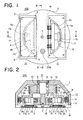
- Fig. 1 is a front view, as seen from the back plate side, of an elevator hoisting machine according to the present invention.
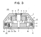
- Fig. 2 is a sectional view, taken along the arrow line II-II, of the elevator hoisting machine of Fig. 1.
- Fig. 3 is a sectional view, taken along the arrow line III-III of the elevator hoisting machine of Fig. 1.
- a hoist 100 has a housing 1 which is of a bowl-like configuration and which has on one side an opening 1a. At the center of a bottom portion 1b of the housing 1, there is formed a center hole 1c, and on the opening 1a side, there is formed a cylindrical portion 1d.
- the opening 1a of the housing 1 is closed by a flat back plate 2.
- Formed in the back plate 2 are two semicircular windows 2a provided for the purpose of allowing maintenance and inspection on a braking device 13 inside, which will be describedbelow.
- These two windows 2a are respectively closed by two rectangular plate-like cover members 4 each detachably fastened in the four corners by bolts 3.
- the cover members 4 prevent foreign matter from entering the interior of the hoist 100; when maintenance is to be performed on the braking device 13, the cover members 4 are removed from the back plate 2.
- the housing 1, the back plate 2, and the cover members 4, constructed as described above, constitute a casing forming inside a space that is hermetically closed.
- the casing is installed in a stationary portion in a hoistway (not shown), with its upper side, as seen in Fig. 1, facing upwards.
- a fixation shaft 5 whose both ends are respectively supported at the center of the back plate 2 and at the center of the bottom surface of the housing 1, is provided so as to extend vertically from the bottom portion 1b of the housing 1 across the space in which a bowl-like member 9 (described below) and the braking device 13 are arranged and which is formed by the housing 1 and the back plate 2.
- the fixation shaft 5 is inserted from outside into the center hole 1c formed at the bottom portion 1b on the housing 1 side, and is fixed to the housing 1, with a flange portion formed at the rear of the fixation shaft being fastened to the periphery of the center hole 1c by bolts 6; its distal end on the other side abuts the inner surface of the back plate 2, and is fastened to the back plate 2 by a bolt 7 passed through the back plate 2.
- a stator 8 Over the entire periphery of the inner peripheral surface of the cylindrical portion 1d of the housing 1, there is provided a stator 8.
- the hermetically closed space formed by the housing 1 and the back plate 2 accommodates a substantially bowl-like member 9.
- the bowl-like member 9 is formed of an iron-type material, such as a casting or steel, and is arranged such that its bottom surface 9a is parallel to the bottom portion 1b of the housing 1, with its center being rotatably supported by the fixation shaft 5 through the intermediation of a bearing 10 so that it rotates with respect to the housing 1 and the back plate 2.
- the bowl-like member 9 is composed of a first cylindrical portion formed on the bottom surface 9a side and a second cylindrical portion formed on the opening edge side and having a diameter larger than the outer diameter of the first cylindrical portion, thus exhibiting a stepped sectional configuration.
- a sheave 9b is formed on the outer peripheral surface of the first cylindrical portion with the smaller diameter on the bottom surface 9a side.
- Four grooves around which main ropes 10 are wrapped are formed in the sheave 9b.
- a car and a counterweight are respectively connected to the ends of the main ropes 10.
- the second cylindrical portion with the larger diameter constitutes a brake drum 9c.
- a permanent magnet 11 is fixed to the entire periphery of the outer peripheral surface of the brake drum 9c.
- the permanent magnet 11 is opposed to the stator 8, and constitutes an electric motor 12 in cooperation with the stator 8.
- the braking device 13 composed of an electromagnetic brake is fixed to the back plate 2.
- the braking device 13 has an electromagnetic magnets 14 arranged at the center, stator cores 15 arranged on the outer sides of the electromagnetic magnets 14 and adapted to be attracted by the electromagnetic magnets 14, brake shoes 16 arranged upright radially outside the stator cores 15, frictional members 17 glued to the outer side surfaces of the brake shoes 16 and opposed to the braking surface 9d of the brake drum 9c, and coil springs 18 compressed between the electromagnetic magnets 14 and the stator cores 15 and urging the frictional members 17 so as to press their contact surfaces 17a against the braking surface 9d.
- the electromagnetic magnets 14, the stator cores 15, the brake shoes 16, the frictional members 17, and the coil springs 18 are arranged symmetrically, each in a pair respectively on both sides of the fixation shaft 5.
- a substantially bar-like magnet 20 constituting the first magnet.
- the magnet 20 is composed of a columnar magnet main body 20a with a small diameter and a base portion 20b in the form of a bolt with a hexagonal hole at its forward end for fixing the magnet main body 20a; the magnet main body 20a is arranged so as to oppose the braking surface 9d of the brake drum 9c; and the magnet main body 20a is inserted from outside into a stepped mounting hole 2b formed in the back plate 2 and fixed by being threadedly engaged with a female screw portion formed in the small diameter hole of the stepped mounting hole 2b.
- the magnet main body 20a is formed of a permanent magnet which is, for example, a ferrite-type material. Since the magnet main body 20a is smaller in diameter than the female screw portion of the stepped mounting hole 2b, the magnet 20 can be drawn out through the mounting hole 2b for maintenance and inspection.
- the substantially bar-shaped magnet 20 is arranged upright on the lower, inner side of the annular braking surface 9d so as to be parallel to the braking surface 9d, with a minute gap therebetween.
- the magnet 20 is provided so as to be circumferentially adjacent to the position where the frictional members 17 and the braking surface 9d come into contact with each other, quickly attracting any abrasion powder or rust powder generated on the braking surface 9d.
- substantially semicircular flat magnet plates 21 constituting the second magnet are respectively glued to the surfaces of the two cover members 4 facing the braking device 13 side, that is, the surfaces opposed to the space defined by the housing 1 and the back plate 2.
- Fig. 4 shows the configuration of the magnet plates 21.
- the magnet plates 21 are formed, for example, of a permanent magnet, which is a ferrite-type material.
- the magnet plates 21 are large enough to entirely close the semicircular windows 2a.
- the magnet plates 21 extend so as to cover the portions in which planes including the planes where the frictional members 17 and the braking surfaces 9d come into contact with each other cross the back plate 2 and the portions around the same.
- the magnet plates 21 attract abrasion powder and rust powder with small grain size scattered in the hermetically closed space inside the hoist.
- the cover members 4 are detachable with respect to the back plate 2, so that, when the cover members 4 are removed, the magnet plates 21 can also be simultaneously removed.
- the movable cores 15 are attracted by the attraction force of the electromagnetic magnets 14 against the restoring force of the coil springs 18, and predetermined gaps are formed between the frictional members 17 and the braking surface 9d of the brake drum 9c, whereby no braking force is generated.
- the electromagnetic magnets 14 have no attraction force, and the frictional members 17 are pressed against the braking surface 9d due to the restoring force of the coil springs 18, whereby a braking force is generated and the sheave 9b stops.
- the hoist 100 is installed at a predeterminedposition in the hoistway, and the main ropes 10 are wrapped around the sheave 9b.
- the sheave 9b is rotated by the electric motor 12 composed of the stator 8 and the permanent magnet 11, and the main ropes 10 are driven, causing the car and the counterweight (not shown) to ascend and descend in opposite directions.
- the elevator hoisting machine 100 of this embodiment is equipped with the sheave 9b around which the elevator main ropes 10 are wrapped, the electric motor 12 connected to the sheave 9b and adapted to rotate the sheave 9b, the cylindrical brake drum 9c connected to the sheave 9b and having on the inner peripheral surface thereof the annular braking surface 9d, the braking device 13 provided on the inner side of the brake drum 9c and adapted to brake the sheave 9b by pressing the frictional members 17 against the braking surface 9d, and the first magnet 20 provided so as to oppose the braking surface 9d and to be detachable, so that any abrasion powder or rust powder generated on the braking surface 9d of the brake drum 9c is quickly attracted by the first magnet 20.
- the braking surface 9d of the brake drum 9c is kept clean for a long period of time, whereby an improvement is achieved in terms of the reliability of the operation of the braking device 13 and, at the same time, a reduction is achieved in the frequency of removal of abrasion powder and rust powder at the time of maintenance and inspection.
- the first magnet 20 is detachably provided, so that the operation of removing abrasion powder and rust powder at the time of maintenance and inspection is facilitated, and the operation time is shortened.
- the second magnets 21 that are detachable, so that any abrasion powder or rust powder scattered in the hermetically closed space is attracted by the second magnets 21, whereby the braking surface 9d is kept still cleaner. Further, since the second magnets 21 are also detachably provided, the operation of removing abrasion powder and rust powder at the time of maintenance and inspection is facilitated, and the operation time is shortened.
- the present invention is most suitable for an elevator to be installed in a small space, in particular, an elevator whose hoist is provided at a position where it is rather difficult to perform maintenance and inspection.
Landscapes
- Engineering & Computer Science (AREA)
- Civil Engineering (AREA)
- Mechanical Engineering (AREA)
- Structural Engineering (AREA)
- Cage And Drive Apparatuses For Elevators (AREA)
- Braking Arrangements (AREA)
Applications Claiming Priority (1)
| Application Number | Priority Date | Filing Date | Title |
|---|---|---|---|
| PCT/JP2003/002243 WO2004076328A1 (ja) | 2003-02-27 | 2003-02-27 | エレベータ用巻上機 |
Publications (1)
| Publication Number | Publication Date |
|---|---|
| EP1598302A1 true EP1598302A1 (de) | 2005-11-23 |
Family
ID=32923101
Family Applications (1)
| Application Number | Title | Priority Date | Filing Date |
|---|---|---|---|
| EP03816062A Withdrawn EP1598302A1 (de) | 2003-02-27 | 2003-02-27 | Hebezeug für aufzug |
Country Status (5)
| Country | Link |
|---|---|
| EP (1) | EP1598302A1 (de) |
| JP (1) | JPWO2004076328A1 (de) |
| KR (1) | KR20040101561A (de) |
| CN (1) | CN1688503A (de) |
| WO (1) | WO2004076328A1 (de) |
Cited By (3)
| Publication number | Priority date | Publication date | Assignee | Title |
|---|---|---|---|---|
| WO2012104478A1 (en) * | 2011-02-02 | 2012-08-09 | Kone Corporation | Method and arrangement for renewing the braking force of a brake of a hoisting machine |
| WO2020114635A1 (de) * | 2018-12-03 | 2020-06-11 | Psa Automobiles Sa | Trommelbremse eines kraftfahrzeugs sowie kraftfahrzeug |
| US11078044B2 (en) | 2017-01-13 | 2021-08-03 | Otis Elevator Company | Ring assembly for elevator governor, governor and elevator system |
Families Citing this family (4)
| Publication number | Priority date | Publication date | Assignee | Title |
|---|---|---|---|---|
| WO2009034642A1 (ja) * | 2007-09-14 | 2009-03-19 | Mitsubishi Electric Corporation | エレベータの巻上機 |
| JP2011030307A (ja) * | 2009-07-22 | 2011-02-10 | Toyota Motor Corp | 回転電機 |
| DE102017214412A1 (de) * | 2017-08-18 | 2019-02-21 | Sms Group Gmbh | Direktantrieb bei Rollen, Walzen und Winden in der Stahl/NE-Industrie |
| CN116262589A (zh) * | 2023-02-17 | 2023-06-16 | 杭州西奥电梯有限公司 | 一种使用钢带的薄式无齿强驱电梯主机 |
Family Cites Families (4)
| Publication number | Priority date | Publication date | Assignee | Title |
|---|---|---|---|---|
| JPH0610074B2 (ja) * | 1985-10-22 | 1994-02-09 | 株式会社日本省力産業研究所 | 電気ホイスト |
| JPH11311272A (ja) * | 1998-04-30 | 1999-11-09 | Hitachi Chem Co Ltd | ディスクブレーキパッド |
| JP3537348B2 (ja) * | 1999-04-05 | 2004-06-14 | 三菱電機株式会社 | トラクション式エレベーター用巻上機 |
| JP2002310189A (ja) * | 2001-04-12 | 2002-10-23 | Toyota Motor Corp | 面接触構造および動力伝達装置 |
-
2003
- 2003-02-27 EP EP03816062A patent/EP1598302A1/de not_active Withdrawn
- 2003-02-27 JP JP2004564061A patent/JPWO2004076328A1/ja active Pending
- 2003-02-27 CN CNA038054965A patent/CN1688503A/zh active Pending
- 2003-02-27 KR KR10-2004-7017257A patent/KR20040101561A/ko not_active Ceased
- 2003-02-27 WO PCT/JP2003/002243 patent/WO2004076328A1/ja not_active Ceased
Non-Patent Citations (1)
| Title |
|---|
| See references of WO2004076328A1 * |
Cited By (6)
| Publication number | Priority date | Publication date | Assignee | Title |
|---|---|---|---|---|
| WO2012104478A1 (en) * | 2011-02-02 | 2012-08-09 | Kone Corporation | Method and arrangement for renewing the braking force of a brake of a hoisting machine |
| CN103502131A (zh) * | 2011-02-02 | 2014-01-08 | 通力股份公司 | 用于恢复提升机的制动器的制动力的方法和配置 |
| CN103502131B (zh) * | 2011-02-02 | 2016-06-08 | 通力股份公司 | 用于恢复提升机的制动器的制动力的方法和配置 |
| US9463956B2 (en) | 2011-02-02 | 2016-10-11 | Kone Corporation | Method and arrangement for renewing the braking force of a brake of a hoisting machine |
| US11078044B2 (en) | 2017-01-13 | 2021-08-03 | Otis Elevator Company | Ring assembly for elevator governor, governor and elevator system |
| WO2020114635A1 (de) * | 2018-12-03 | 2020-06-11 | Psa Automobiles Sa | Trommelbremse eines kraftfahrzeugs sowie kraftfahrzeug |
Also Published As
| Publication number | Publication date |
|---|---|
| CN1688503A (zh) | 2005-10-26 |
| KR20040101561A (ko) | 2004-12-02 |
| WO2004076328A1 (ja) | 2004-09-10 |
| JPWO2004076328A1 (ja) | 2006-06-01 |
Similar Documents
| Publication | Publication Date | Title |
|---|---|---|
| EP1598302A1 (de) | Hebezeug für aufzug | |
| US20160031674A1 (en) | Braking apparatus and elevator hoisting machine that uses same | |
| CN107848761A (zh) | 电梯用曳引机和电梯 | |
| CN103261079B (zh) | 电梯用电磁制动装置 | |
| JPH09506237A (ja) | エレベータ機械装置 | |
| SG186575A1 (en) | Traction machine for elevator | |
| JP5809531B2 (ja) | エレベーターの薄型巻上機 | |
| JP2004338915A (ja) | エレベータ用巻上機 | |
| CN205575342U (zh) | 带挡油装置的永磁同步曳引机 | |
| JP2004107048A (ja) | エレベーター用巻上機 | |
| JP4601687B2 (ja) | エレベーター用巻上機 | |
| JP2003267648A (ja) | エレベーター巻上機 | |
| JP5919856B2 (ja) | エレベータ巻上機用制動装置 | |
| EP1553040A1 (de) | Antriebsvorrichtung für aufzug | |
| JP2014159319A (ja) | エレベーター装置及びそのブレーキ装置 | |
| JP2007218333A (ja) | ブレーキ装置 | |
| JP2004075360A (ja) | エレベーター巻上機 | |
| JP4408347B2 (ja) | エレベーター用巻上機 | |
| JP6505886B1 (ja) | 巻上機の電磁ディスクブレーキ装置 | |
| JP4812544B2 (ja) | エレベーター用巻上機 | |
| WO2003008320A1 (en) | Elevator hoist | |
| JPH11335041A (ja) | エレベータ用巻上機 | |
| CN111377340A (zh) | 电梯用曳引机及电梯 | |
| JP2015157662A (ja) | 巻上機 | |
| JP4522181B2 (ja) | エレベーター用巻上機 |
Legal Events
| Date | Code | Title | Description |
|---|---|---|---|
| PUAI | Public reference made under article 153(3) epc to a published international application that has entered the european phase |
Free format text: ORIGINAL CODE: 0009012 |
|
| 17P | Request for examination filed |
Effective date: 20041004 |
|
| AK | Designated contracting states |
Kind code of ref document: A1 Designated state(s): AT BE BG CH CY CZ DE DK EE ES FI FR GB GR HU IE IT LI LU MC NL PT SE SI SK TR |
|
| AX | Request for extension of the european patent |
Extension state: AL LT LV MK RO |
|
| STAA | Information on the status of an ep patent application or granted ep patent |
Free format text: STATUS: THE APPLICATION HAS BEEN WITHDRAWN |
|
| RBV | Designated contracting states (corrected) |
Designated state(s): AT BE BG CH CY CZ DE DK EE ES FI FR GB GR HU IE IT LI LU MC NL PT SE SI SK TR |
|
| 18W | Application withdrawn |
Effective date: 20051213 |