EP1597477B1 - Procede de montage de pales de rotor - Google Patents
Procede de montage de pales de rotor Download PDFInfo
- Publication number
- EP1597477B1 EP1597477B1 EP04703365A EP04703365A EP1597477B1 EP 1597477 B1 EP1597477 B1 EP 1597477B1 EP 04703365 A EP04703365 A EP 04703365A EP 04703365 A EP04703365 A EP 04703365A EP 1597477 B1 EP1597477 B1 EP 1597477B1
- Authority
- EP
- European Patent Office
- Prior art keywords
- rotor blade
- rotor
- hub
- mounting
- nacelle
- Prior art date
- Legal status (The legal status is an assumption and is not a legal conclusion. Google has not performed a legal analysis and makes no representation as to the accuracy of the status listed.)
- Expired - Lifetime
Links
Images
Classifications
-
- F—MECHANICAL ENGINEERING; LIGHTING; HEATING; WEAPONS; BLASTING
- F03—MACHINES OR ENGINES FOR LIQUIDS; WIND, SPRING, OR WEIGHT MOTORS; PRODUCING MECHANICAL POWER OR A REACTIVE PROPULSIVE THRUST, NOT OTHERWISE PROVIDED FOR
- F03D—WIND MOTORS
- F03D13/00—Assembly, mounting or commissioning of wind motors; Arrangements specially adapted for transporting wind motor components
- F03D13/10—Assembly of wind motors; Arrangements for erecting wind motors
-
- F—MECHANICAL ENGINEERING; LIGHTING; HEATING; WEAPONS; BLASTING
- F03—MACHINES OR ENGINES FOR LIQUIDS; WIND, SPRING, OR WEIGHT MOTORS; PRODUCING MECHANICAL POWER OR A REACTIVE PROPULSIVE THRUST, NOT OTHERWISE PROVIDED FOR
- F03D—WIND MOTORS
- F03D1/00—Wind motors with rotation axis substantially parallel to the air flow entering the rotor
- F03D1/06—Rotors
- F03D1/065—Rotors characterised by their construction elements
- F03D1/0658—Arrangements for fixing wind-engaging parts to a hub
-
- F—MECHANICAL ENGINEERING; LIGHTING; HEATING; WEAPONS; BLASTING
- F05—INDEXING SCHEMES RELATING TO ENGINES OR PUMPS IN VARIOUS SUBCLASSES OF CLASSES F01-F04
- F05B—INDEXING SCHEME RELATING TO WIND, SPRING, WEIGHT, INERTIA OR LIKE MOTORS, TO MACHINES OR ENGINES FOR LIQUIDS COVERED BY SUBCLASSES F03B, F03D AND F03G
- F05B2230/00—Manufacture
- F05B2230/60—Assembly methods
-
- F—MECHANICAL ENGINEERING; LIGHTING; HEATING; WEAPONS; BLASTING
- F05—INDEXING SCHEMES RELATING TO ENGINES OR PUMPS IN VARIOUS SUBCLASSES OF CLASSES F01-F04
- F05B—INDEXING SCHEME RELATING TO WIND, SPRING, WEIGHT, INERTIA OR LIKE MOTORS, TO MACHINES OR ENGINES FOR LIQUIDS COVERED BY SUBCLASSES F03B, F03D AND F03G
- F05B2240/00—Components
- F05B2240/20—Rotors
- F05B2240/21—Rotors for wind turbines
-
- Y—GENERAL TAGGING OF NEW TECHNOLOGICAL DEVELOPMENTS; GENERAL TAGGING OF CROSS-SECTIONAL TECHNOLOGIES SPANNING OVER SEVERAL SECTIONS OF THE IPC; TECHNICAL SUBJECTS COVERED BY FORMER USPC CROSS-REFERENCE ART COLLECTIONS [XRACs] AND DIGESTS
- Y02—TECHNOLOGIES OR APPLICATIONS FOR MITIGATION OR ADAPTATION AGAINST CLIMATE CHANGE
- Y02E—REDUCTION OF GREENHOUSE GAS [GHG] EMISSIONS, RELATED TO ENERGY GENERATION, TRANSMISSION OR DISTRIBUTION
- Y02E10/00—Energy generation through renewable energy sources
- Y02E10/70—Wind energy
- Y02E10/72—Wind turbines with rotation axis in wind direction
-
- Y—GENERAL TAGGING OF NEW TECHNOLOGICAL DEVELOPMENTS; GENERAL TAGGING OF CROSS-SECTIONAL TECHNOLOGIES SPANNING OVER SEVERAL SECTIONS OF THE IPC; TECHNICAL SUBJECTS COVERED BY FORMER USPC CROSS-REFERENCE ART COLLECTIONS [XRACs] AND DIGESTS
- Y02—TECHNOLOGIES OR APPLICATIONS FOR MITIGATION OR ADAPTATION AGAINST CLIMATE CHANGE
- Y02E—REDUCTION OF GREENHOUSE GAS [GHG] EMISSIONS, RELATED TO ENERGY GENERATION, TRANSMISSION OR DISTRIBUTION
- Y02E10/00—Energy generation through renewable energy sources
- Y02E10/70—Wind energy
- Y02E10/728—Onshore wind turbines
-
- Y—GENERAL TAGGING OF NEW TECHNOLOGICAL DEVELOPMENTS; GENERAL TAGGING OF CROSS-SECTIONAL TECHNOLOGIES SPANNING OVER SEVERAL SECTIONS OF THE IPC; TECHNICAL SUBJECTS COVERED BY FORMER USPC CROSS-REFERENCE ART COLLECTIONS [XRACs] AND DIGESTS
- Y02—TECHNOLOGIES OR APPLICATIONS FOR MITIGATION OR ADAPTATION AGAINST CLIMATE CHANGE
- Y02P—CLIMATE CHANGE MITIGATION TECHNOLOGIES IN THE PRODUCTION OR PROCESSING OF GOODS
- Y02P70/00—Climate change mitigation technologies in the production process for final industrial or consumer products
- Y02P70/50—Manufacturing or production processes characterised by the final manufactured product
-
- Y—GENERAL TAGGING OF NEW TECHNOLOGICAL DEVELOPMENTS; GENERAL TAGGING OF CROSS-SECTIONAL TECHNOLOGIES SPANNING OVER SEVERAL SECTIONS OF THE IPC; TECHNICAL SUBJECTS COVERED BY FORMER USPC CROSS-REFERENCE ART COLLECTIONS [XRACs] AND DIGESTS
- Y10—TECHNICAL SUBJECTS COVERED BY FORMER USPC
- Y10T—TECHNICAL SUBJECTS COVERED BY FORMER US CLASSIFICATION
- Y10T29/00—Metal working
- Y10T29/49—Method of mechanical manufacture
- Y10T29/49316—Impeller making
-
- Y—GENERAL TAGGING OF NEW TECHNOLOGICAL DEVELOPMENTS; GENERAL TAGGING OF CROSS-SECTIONAL TECHNOLOGIES SPANNING OVER SEVERAL SECTIONS OF THE IPC; TECHNICAL SUBJECTS COVERED BY FORMER USPC CROSS-REFERENCE ART COLLECTIONS [XRACs] AND DIGESTS
- Y10—TECHNICAL SUBJECTS COVERED BY FORMER USPC
- Y10T—TECHNICAL SUBJECTS COVERED BY FORMER US CLASSIFICATION
- Y10T29/00—Metal working
- Y10T29/49—Method of mechanical manufacture
- Y10T29/49316—Impeller making
- Y10T29/49327—Axial blower or fan
-
- Y—GENERAL TAGGING OF NEW TECHNOLOGICAL DEVELOPMENTS; GENERAL TAGGING OF CROSS-SECTIONAL TECHNOLOGIES SPANNING OVER SEVERAL SECTIONS OF THE IPC; TECHNICAL SUBJECTS COVERED BY FORMER USPC CROSS-REFERENCE ART COLLECTIONS [XRACs] AND DIGESTS
- Y10—TECHNICAL SUBJECTS COVERED BY FORMER USPC
- Y10T—TECHNICAL SUBJECTS COVERED BY FORMER US CLASSIFICATION
- Y10T29/00—Metal working
- Y10T29/49—Method of mechanical manufacture
- Y10T29/49316—Impeller making
- Y10T29/49329—Centrifugal blower or fan
-
- Y—GENERAL TAGGING OF NEW TECHNOLOGICAL DEVELOPMENTS; GENERAL TAGGING OF CROSS-SECTIONAL TECHNOLOGIES SPANNING OVER SEVERAL SECTIONS OF THE IPC; TECHNICAL SUBJECTS COVERED BY FORMER USPC CROSS-REFERENCE ART COLLECTIONS [XRACs] AND DIGESTS
- Y10—TECHNICAL SUBJECTS COVERED BY FORMER USPC
- Y10T—TECHNICAL SUBJECTS COVERED BY FORMER US CLASSIFICATION
- Y10T29/00—Metal working
- Y10T29/49—Method of mechanical manufacture
- Y10T29/49826—Assembling or joining
- Y10T29/4984—Retaining clearance for motion between assembled parts
Definitions
- the present invention relates to a method of assembling rotor blades on a rotor hub connected to a nacelle of a wind turbine as defined in the preamble of claim 1.
- a method is for example from the EP-A-1 101 936 known.
- Rotor blades for wind turbines are well known. With increasing size of the wind turbines and increasing power and the size of the rotor blades and their own weight increases. To mount the components therefore cranes are required, which can transport loads with higher weight to higher altitudes. Accordingly, the required cranes are larger.
- the object of the invention is to simplify the assembly of the rotor blades and to improve the handling of the rotor blades.
- the object of the invention is achieved by a method for rotor blade assembly according to claim 1.
- the method for mounting rotor blades on a rotor hub is done by rotating the rotor hub in a predetermined first position, attaching a rotor blade, rotating the rotor hub with auxiliary rotor blade in a predetermined second position, wherein the rotation the rotor hub takes place in the direction of the gravitational force of the already mounted first rotor blade.
- a crane can be used, which is also sufficient for mounting the rotor hub itself or the nacelle.
- the nacelle is rotated by 180 degrees before the second rotor blade is attached. This procedure allows the assembly of the second rotor blade, without the crane having to change its location, since the mounting position of the rotor blade is in turn on the side of the wind turbine on which the crane is constructed by the rotation of the nacelle
- the rotor hub is rotated by means of the second rotor blade in a further predetermined position, the nacelle rotated again by 180 degrees and attached to a third rotor blade 23.
- This assembly of the third rotor blade is possible without a change in the location of the crane and by saving the time-consuming relocation of the crane, the rotor blades can install time-saving.
- the crane can engage the rotor blade and more preferably at a through-hole of the rotor blade and thus delay the rotation of the rotor blade in the direction of gravity by an oppositely directed force.
- the rotation can be easily controlled and influenced in a simple manner.
- the rotor blade has at least one through hole in the rotor blade at a predetermined position. This has the particular advantage that handling means, which can reach through the rotor blade, are faster and safer to use than the known handling with straps and lashing cables.
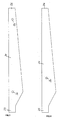
- FIG. 1 a simplified representation of the rotor blade 21 is shown.
- This rotor blade 21 has two through-holes 30, 32 in its longitudinal direction between the rotor blade root 25 and the rotor blade tip 26.
- the through-hole 32 is formed in the region of the rotor blade tip 26, while the through-hole 30 is located in the rotor blade rooting region. These positions are set so that a safe handling of the rotor blade is ensured when mounted on a rotor hub of a wind turbine.
- the determination of the position for the holes 30, 32 takes place in consideration of a connection to the supporting structure of the rotor blade 21.
- Fig. 2 shows a side view of the rotor blade 21 with only one through hole 30.
- This single through hole 30 is arranged in a meaningful manner in the center of gravity of the rotor blade, so that even with a handling means, the rotor blade is safely handled. Again, of course, a connection with the supporting structure is taken into account.
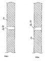
- FIGS. 3 and 4 By way of example, alternative embodiments of the through holes are shown.
- a cylindrical through hole 30, 32 is shown, which can be closed by suitable covers.
- Fig. 4 shows a through hole 30, 32, which is also cylindrical in a central portion, wherein the surfaces of the rotor blade 21 adjacent end portions of the through hole 30, 32 but widen.
- This broadening allows for improved attachment of covers that close the through-hole 30, 32 to prevent dirt and moisture from entering, and to inhibit flow of the rotor blade through the hole by being flush with the surface. It come to the attachment of such (not shown) cover different, known per se options, such. As an undercut, thread, etc.
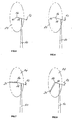
- Fig. 5 is the initial situation of the inventive method for attaching rotor blades on the rotor hub of a wind turbine shown.
- rotor blades with through holes as in Fig. 1 and 2 shown used.
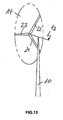
- Figures 5-13 are the components required to explain the invention strong shown in simplified form.
- the reference numeral 10 denotes the tower of a wind turbine
- 12 indicates the orientation of the nacelle
- 14 represents the rotor circuit
- 16, 17 and 18 indicate the orientation of the rotor blade terminals
- 21, 22 and 23 denote mounted rotor blades.
- the through holes 30, 32 For mounting the rotor blades on the rotor hub of the nacelle of a wind turbine handling means in the through holes 30, 32 are fixed in order to be able to safely transport the rotor blades with them and with the aid of a crane up to the rotor hub. Since the through holes extend between the suction and the pressure side of the rotor blade, the rotor blades can be handled safely in a horizontal position. The provision of the through-holes in the rotor blades described above greatly simplifies the method of assembling these rotor blades described below.
- Fig. 5 is the rotor circuit 14 in the viewing direction behind the tower 10 of the wind turbine and the rotor blade terminals 16, 17, 18 are in the positions 12 clock, 4 clock and 8 clock.
- the rotor hub is now brought into a predetermined position. This is in Fig. 6 shown. It is essential that the rotor blade connection 17 is now in the 9 o'clock position. Accordingly, the rotor blade connection 16 is now in the 1 o'clock position and the rotor blade connection 18 is in the 5 o'clock position.
- Fig. 8 The next step is in Fig. 8 shown.
- the rotor blade 21 is lowered to the 7 o'clock position. This lowering can be done by gravity.
- the crane (not shown), which has lifted the rotor blade 21 to the mounting position, counteract the rotation and thus force a controlled rotation.
- Fig. 9 illustrates that with unchanged position of the rotor hub, the nacelle was rotated by 180 degrees, so that the rotor circuit 14 is in the direction of observation in front of the tower 10.
- the rotor blade 21 is now in the 5 o'clock position, the rotor blade connection 16 in the 1 o'clock position and the rotor blade connection 18 in the 9 o'clock position.
- a further rotor blade raised in a horizontal position by the crane can now be attached to this rotor blade connection 18 without the crane having to change its position.
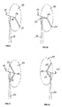
- Fig. 10 The resulting situation is in Fig. 10 shown. There, the rotor blade connection 16 is still in the 1 o'clock position, the first rotor blade 21 in the 5 o'clock position, while the second rotor blade 22 is now shown in the 9 o'clock position.
- the rotor blade 21 is pivoted by means of the crane from the 5 o'clock position to the 7 o'clock position.
- the second rotor blade 22 reaches the 11 o'clock position and the rotor blade connection 16 reaches the 3 o'clock position.
- the gondola is again rotated 180 degrees.
- Fig. 12 The result of this rotation is in Fig. 12 shown. From the perspective of the beholder, the rotor circuit 14 is now behind the tower 10. This is the same position of the rotor hub, the first rotor blade 21 in the 5 o'clock position, the second rotor blade 22 is in the 1 o'clock position and the rotor blade connection 16 is in the 9 o'clock position. Thus, can Again, without a location change of the crane, a third rotor blade are attached to this rotor blade connection 16. This is in the Fig. 13 shown. The first rotor blade 21 is in the 5 o'clock position, the second rotor blade 22 in the 1 o'clock position and the third rotor blade 23 in the 9 o'clock position. Thus, the inventive method is completed and all three rotor blades have been attached to the wind turbine.
Landscapes
- Engineering & Computer Science (AREA)
- Life Sciences & Earth Sciences (AREA)
- Sustainable Development (AREA)
- Sustainable Energy (AREA)
- Chemical & Material Sciences (AREA)
- Combustion & Propulsion (AREA)
- Mechanical Engineering (AREA)
- General Engineering & Computer Science (AREA)
- Wind Motors (AREA)
- Hydraulic Turbines (AREA)
Abstract
Claims (4)
- Procédé de montage de pales de rotor sur un moyeu de rotor d'une installation éolienne, le moyeu de rotor étant relié à une nacelle, avec les étapes consistant à :a) pivoter le moyeu de rotor dans une première position prédéfinie,b) monter une pale de rotor (21),c) pivoter le moyeu de rotor à l'aide de la première pale de rotor (21) dans une deuxième position prédéfinie,d) monter une deuxième pale de rotor (22),caractérisé en ce que
la rotation du moyeu de rotor est effectuée en direction de l'action de la force de gravité de la première pale de rotor (21),
la nacelle étant pivotée de 180 degrés avant que la deuxième pale de rotor (22) ne soit montée. - Procédé selon la revendication 1, caractérisé en ce quea) le moyeu de rotor est pivoté à l'aide de la deuxième pale de rotor (22) dans une autre position prédéfinie,b) la nacelle est de nouveau pivotée de 180 degrés etc) une troisième pale de rotor (23) est montée.
- Procédé selon l'une quelconque des revendications 1 ou 2,
caractérisé en ce qu'une grue saisit une pale de rotor (21, 22) et assiste la rotation du moyeu. - Procédé selon la revendication 3,
caractérisé en ce que la grue saisit un trou de passage (30, 32) de la pale de rotor (21, 22).
Priority Applications (6)
| Application Number | Priority Date | Filing Date | Title |
|---|---|---|---|
| DK10154694.3T DK2180180T3 (en) | 2003-02-10 | 2004-01-20 | Rotor blade for a wind power plant with through holes for handling |
| EP10185397.6A EP2273101B1 (fr) | 2003-02-10 | 2004-01-20 | Procédé d'assemblage des aubes d'une éolienne |
| EP10154694.3A EP2180180B1 (fr) | 2003-02-10 | 2004-01-20 | Aube d'une éolienne avec des trous débouchants de manutention |
| SI200431386T SI1597477T1 (sl) | 2003-02-10 | 2004-01-20 | Postopek namestitve listov rotorja |
| CY20101100390T CY1109999T1 (el) | 2003-02-10 | 2010-04-30 | Μεθοδος για τη συναρμολογηση των πτερυγιων ενος δρομεα |
| CY20161100551T CY1117935T1 (el) | 2003-02-10 | 2016-06-17 | Πτερυγιο δρομεα με διαμπρερεις οπες για το χειρισμο |
Applications Claiming Priority (3)
| Application Number | Priority Date | Filing Date | Title |
|---|---|---|---|
| DE10305543 | 2003-02-10 | ||
| DE10305543A DE10305543C5 (de) | 2003-02-10 | 2003-02-10 | Verfahren zur Montage von Rotorblättern sowie ein Rotorblatt für eine Windenergieanlage |
| PCT/EP2004/000368 WO2004070203A2 (fr) | 2003-02-10 | 2004-01-20 | Procede de montage de pales de rotor, et pale de rotor pour eolienne |
Related Child Applications (2)
| Application Number | Title | Priority Date | Filing Date |
|---|---|---|---|
| EP10154694.3A Division EP2180180B1 (fr) | 2003-02-10 | 2004-01-20 | Aube d'une éolienne avec des trous débouchants de manutention |
| EP10154694.3 Division-Into | 2010-02-25 |
Publications (2)
| Publication Number | Publication Date |
|---|---|
| EP1597477A2 EP1597477A2 (fr) | 2005-11-23 |
| EP1597477B1 true EP1597477B1 (fr) | 2010-04-14 |
Family
ID=32747712
Family Applications (3)
| Application Number | Title | Priority Date | Filing Date |
|---|---|---|---|
| EP10185397.6A Expired - Lifetime EP2273101B1 (fr) | 2003-02-10 | 2004-01-20 | Procédé d'assemblage des aubes d'une éolienne |
| EP04703365A Expired - Lifetime EP1597477B1 (fr) | 2003-02-10 | 2004-01-20 | Procede de montage de pales de rotor |
| EP10154694.3A Expired - Lifetime EP2180180B1 (fr) | 2003-02-10 | 2004-01-20 | Aube d'une éolienne avec des trous débouchants de manutention |
Family Applications Before (1)
| Application Number | Title | Priority Date | Filing Date |
|---|---|---|---|
| EP10185397.6A Expired - Lifetime EP2273101B1 (fr) | 2003-02-10 | 2004-01-20 | Procédé d'assemblage des aubes d'une éolienne |
Family Applications After (1)
| Application Number | Title | Priority Date | Filing Date |
|---|---|---|---|
| EP10154694.3A Expired - Lifetime EP2180180B1 (fr) | 2003-02-10 | 2004-01-20 | Aube d'une éolienne avec des trous débouchants de manutention |
Country Status (20)
| Country | Link |
|---|---|
| US (1) | US7353603B2 (fr) |
| EP (3) | EP2273101B1 (fr) |
| JP (2) | JP4335214B2 (fr) |
| KR (2) | KR100945128B1 (fr) |
| CN (2) | CN100447405C (fr) |
| AR (1) | AR043122A1 (fr) |
| AT (1) | ATE464476T1 (fr) |
| AU (2) | AU2004209032B2 (fr) |
| BR (1) | BRPI0407109B1 (fr) |
| CA (1) | CA2515082C (fr) |
| CY (3) | CY1109999T1 (fr) |
| DE (2) | DE10305543C5 (fr) |
| DK (3) | DK1597477T3 (fr) |
| ES (3) | ES2570978T3 (fr) |
| HU (1) | HUE028646T2 (fr) |
| NZ (2) | NZ582987A (fr) |
| PL (2) | PL216992B1 (fr) |
| PT (2) | PT1597477E (fr) |
| SI (3) | SI2273101T1 (fr) |
| WO (1) | WO2004070203A2 (fr) |
Cited By (2)
| Publication number | Priority date | Publication date | Assignee | Title |
|---|---|---|---|---|
| DE102019106969A1 (de) * | 2019-03-19 | 2020-09-24 | Wobben Properties Gmbh | Verfahren zur Montage von Rotorblättern einer Windenergieanlage |
| EP3805553A1 (fr) | 2019-10-08 | 2021-04-14 | Wobben Properties GmbH | Procédé de montage de pales de rotor d'une éolienne |
Families Citing this family (51)
| Publication number | Priority date | Publication date | Assignee | Title |
|---|---|---|---|---|
| CN1906410B (zh) | 2004-01-26 | 2010-11-10 | 维斯塔斯风力系统有限公司 | 用于操纵风轮机叶片的方法及其系统 |
| DK200501312A (da) | 2005-09-21 | 2007-03-22 | Lm Glasfiber As | Fastgörelsesanordninger på vinge |
| DE102006008428B4 (de) * | 2006-02-23 | 2013-07-18 | Repower Systems Ag | Montage/Demontage eines Rotorblattes |
| EP1925582B1 (fr) * | 2006-11-23 | 2010-06-23 | Siemens Aktiengesellschaft | Procédé et dispositif de montage de pales d'éoliennes |
| ATE471909T1 (de) * | 2006-11-23 | 2010-07-15 | Siemens Ag | Verfahren und vorrichtung zur montage von windturbinenschaufeln |
| WO2009061401A1 (fr) * | 2007-11-05 | 2009-05-14 | Thomas Stewart Bernatz | Ensemble rotor d'éolienne à axe horizontal avec des pales de rotor à corps portants |
| GB0818466D0 (en) * | 2008-10-08 | 2008-11-12 | Blade Dynamics Ltd | A wind turbine rotor |
| US20120000071A1 (en) * | 2009-03-19 | 2012-01-05 | Technip France | Offshore wind turbine installation system and method |
| EP2345811B1 (fr) | 2010-01-14 | 2012-10-03 | Siemens Aktiengesellschaft | Pince pour fixer la pale d'une éolienne et procédé d'installation de pales d'éolienne |
| JP4547039B1 (ja) * | 2010-02-23 | 2010-09-22 | 株式会社日本製鋼所 | 風力発電用ローターブレードの取り付け方法 |
| DE202010015616U1 (de) * | 2010-11-18 | 2012-03-01 | Liebherr-Werk Ehingen Gmbh | Kran |
| EP2377674A1 (fr) * | 2010-04-16 | 2011-10-19 | Siemens Aktiengesellschaft | Procédé de fabrication de pale de rotor d'éolienne et pale de rotor d'éolienne |
| US8562302B2 (en) * | 2010-07-06 | 2013-10-22 | General Electric Company | Wind turbine blade with integrated handling mechanism attachment bores |
| EP2616671B1 (fr) * | 2010-09-15 | 2017-07-26 | Vestas Wind Systems A/S | Structures d'aube de turbine éolienne, ensembles de levage et procédés de manipulation d'aubes |
| EP2431970A1 (fr) | 2010-09-21 | 2012-03-21 | Fraunhofer-Gesellschaft zur Förderung der Angewandten Forschung e.V. | Générateur de filigrane, décodeur de filigrane, procédé de fourniture d'un signal de filigrane basé sur des données discrètes et procédé de fourniture de données discrètes dépendantes d'un signal de filigrane |
| DK2453129T3 (da) * | 2010-11-11 | 2014-12-15 | Alstom Renewable Technologies | Vinge til en vindmølle |
| US8240993B2 (en) * | 2011-01-04 | 2012-08-14 | General Electric Company | System and method of manipulating a boundary layer across a rotor blade of a wind turbine |
| WO2012148012A1 (fr) * | 2011-04-26 | 2012-11-01 | 주식회사 포스코건설 | Pale de rotor pour turbine de génération électrique marémotrice et procédé pour sa fabrication |
| DE102011017801B8 (de) | 2011-04-29 | 2013-05-08 | Wobben Properties Gmbh | Windenergieanlage mit einer Mehrzahl von Verschiebeeinheiten zur Montage oder Demontage von Rotorblättern und Verfahren hierzu |
| EP2715112B1 (fr) | 2011-05-27 | 2015-11-04 | Vestas Wind Systems A/S | Appareil de manipulation d'une pale d'éolienne et procédé de manipulation de pale |
| DE102011076937B3 (de) | 2011-06-03 | 2012-12-06 | Aloys Wobben | Windenergieanlagen-Rotorblatt und Verfahren zur Montage eines Windenergieanlagen-Rotorblattes |
| DE102011116189B3 (de) * | 2011-06-21 | 2012-10-04 | Repower Systems Se | Lasthandhabungsvorrichtung zum Anheben von Rotorblättern in eine Montageposition und Verfahren zur Montage von Rotorblättern an der Rotornabe einer Windenergieanlage |
| DK2573384T3 (en) | 2011-09-21 | 2017-07-03 | Siemens Ag | Method for rotating the rotor of a wind turbine and means for use in this method |
| EP2573385A1 (fr) | 2011-09-22 | 2013-03-27 | Siemens Aktiengesellschaft | Procédé de rotation du rotor d'une éolienne et supports pour utiliser ce procédé |
| EP2574774B1 (fr) | 2011-09-27 | 2014-08-06 | Siemens Aktiengesellschaft | Procédé pour faire tourner le rotor d'une éolienne et moyens pour utiliser ce procédé |
| DE102011084140A1 (de) | 2011-10-07 | 2013-04-11 | Wobben Properties Gmbh | Verfahren und Vorrichtung zum Montieren eines Rotors einer Windenergieanlage |
| EP2589795B1 (fr) | 2011-11-04 | 2015-03-04 | Siemens Aktiengesellschaft | Cadre de levage pour lever une pale de rotor d'éolienne et procédé de montage de pales de rotor d'éolienne |
| DK2607684T3 (en) | 2011-12-19 | 2015-04-27 | Siemens Ag | Means for rotation of the rotor of a wind turbine and method for the rotation of the rotor |
| EP2617986B1 (fr) | 2012-01-20 | 2014-04-30 | Siemens Aktiengesellschaft | Procédé et agencement pour l'installation d'une pale de rotor |
| EP2617987B1 (fr) | 2012-01-20 | 2014-04-30 | Siemens Aktiengesellschaft | Procédé et agencement pour l'installation d'une pale de rotor |
| EP2650537B1 (fr) | 2012-04-11 | 2014-12-31 | Siemens Aktiengesellschaft | Assemblage avec contrepoids pour équilibrer et aligner le rotor partiellement monté d'une éolienne, et méthode associée |
| KR101380663B1 (ko) * | 2012-06-28 | 2014-04-04 | 삼성중공업 주식회사 | 풍력발전용 블레이드 유지보수 방법 및 이에 사용되는 안전고리 결속장치 |
| KR101400205B1 (ko) * | 2013-02-06 | 2014-05-27 | 삼성중공업 주식회사 | 밸런싱 장치 및 이를 이용한 풍력 발전기용 블레이드 장착 방법 |
| DK2767708T3 (en) | 2013-02-13 | 2015-08-10 | Siemens Ag | Turning device for rotating the rotatable part of a wind turbine |
| DE102013211751A1 (de) | 2013-06-21 | 2014-12-24 | Wobben Properties Gmbh | Verfahren zum Montieren eines Windenergieanlagen-Rotorblattes sowie Windenergieanlagen-Rotorblatt |
| US9638163B2 (en) | 2014-02-20 | 2017-05-02 | General Electric Company | Methods and systems for removing and/or installing wind turbine rotor blades |
| US10113530B2 (en) | 2014-02-20 | 2018-10-30 | General Electric Company | Methods and systems for removing and/or installing wind turbine rotor blades |
| US9651021B2 (en) | 2014-09-09 | 2017-05-16 | General Electric Company | System and method for removing and/or installing a rotor blade of a wind turbine |
| US9890022B2 (en) | 2015-05-07 | 2018-02-13 | General Electric Company | Method for suspending a rotor blade from a hub of a wind turbine |
| US9821417B2 (en) | 2015-05-07 | 2017-11-21 | General Electric Company | System and method for replacing a pitch bearing |
| JP6546803B2 (ja) * | 2015-07-22 | 2019-07-17 | 株式会社日立製作所 | 風力発電装置及び風力発電装置における無線通信方法 |
| US10066601B2 (en) | 2015-10-22 | 2018-09-04 | General Electric Company | System and method for manufacturing wind turbine rotor blades for simplified installation and removal |
| WO2017108049A1 (fr) * | 2015-12-22 | 2017-06-29 | Vestas Wind Systems A/S | Procédés pour monter ou démonter des éléments d'éolienne d'une éolienne à rotors multiples |
| DE102016110747A1 (de) | 2016-06-10 | 2017-12-14 | Wobben Properties Gmbh | Rotorblatt, Windenergieanlage sowie Verfahren zur Montage und zur Herstellung eines Rotorblattes |
| CN110199116B (zh) | 2016-12-21 | 2021-05-07 | 维斯塔斯风力系统有限公司 | 风力涡轮机维修或施工方法和设备 |
| US10508645B2 (en) | 2017-07-17 | 2019-12-17 | General Electric Company | System and method for suspending a rotor blade of a wind turbine uptower |
| DK3450744T3 (da) | 2017-08-31 | 2022-06-20 | Gen Electric | Fremgangsmåde og værktøj til adskillelse af et pitchleje fra et vindmøllenav |
| DK179738B1 (en) | 2017-10-11 | 2019-04-30 | Ravn Niels | Wind-Driven Energy Converting Device |
| EP3617498B1 (fr) * | 2018-08-29 | 2022-07-20 | General Electric Renovables España S.L. | Procédés de rotation d'un moyen d'éolienne |
| CN112664392B (zh) | 2019-10-15 | 2025-09-05 | 通用电气可再生能源西班牙有限公司 | 用于在延长的维护期间锁定风力涡轮转子的系统和方法 |
| ES2966934T3 (es) | 2019-12-31 | 2024-04-25 | Nordex Energy Spain Sau | Método de montaje de pala en un buje de rotor de una turbina eólica |
Family Cites Families (18)
| Publication number | Priority date | Publication date | Assignee | Title |
|---|---|---|---|---|
| GB452611A (en) * | 1935-08-24 | 1936-08-26 | Charles Richard Fairey | Improvements in metal airscrews |
| US4008817A (en) * | 1972-02-18 | 1977-02-22 | United States Steel Corporation | Saw blade handling device |
| US4439108A (en) * | 1982-06-08 | 1984-03-27 | Richard Will | Windmill having centrifically feathered rotors to control rotor speed |
| JPH01182285A (ja) * | 1987-12-29 | 1989-07-20 | Nkk Corp | 高架タンク等の耐震強度向上方法 |
| JPH02112700A (ja) * | 1988-10-19 | 1990-04-25 | Fujitsu Ltd | 軸流フアンのブレード構造 |
| IT219392Z2 (it) * | 1990-03-12 | 1993-02-26 | Sistema di fissaggio tra pala estrusa a struttura cava per ventilatore assiale e gambo della pala inserito | |
| JPH06193550A (ja) * | 1992-12-25 | 1994-07-12 | Ishikawajima Harima Heavy Ind Co Ltd | 風力発電装置の回転翼固定方法 |
| CN2228557Y (zh) * | 1995-08-10 | 1996-06-05 | 邓宏博 | 直立平转风力发电机 |
| JP3700306B2 (ja) * | 1997-01-27 | 2005-09-28 | Jfeエンジニアリング株式会社 | 風力発電装置の建設方法 |
| JPH1182285A (ja) | 1997-09-16 | 1999-03-26 | Nkk Corp | 風力発電装置の建設方法、クライミングクレーン装置お よびそれを用いたメンテナンス方法 |
| DK173530B2 (da) * | 1999-11-17 | 2005-07-18 | Siemens Wind Power As | Fremgangsmåde til montering af hovedkomponenter i kabine på vindmölle og en sådan kabine til vindmölle |
| US6364609B1 (en) * | 2000-05-01 | 2002-04-02 | Robert J. Barnes | Wind turbine having ground winch pivot erection support structure |
| WO2001094249A1 (fr) * | 2000-06-06 | 2001-12-13 | Demag Mobile Cranes Gmbh | Procede et dispositif de montage d'une eolienne |
| DE10031473C1 (de) * | 2000-06-28 | 2002-02-28 | Tacke Windenergie Gmbh | Vorrichtung zum Drehen einer mit einem Rotor verbundenen oder gekoppelten Welle einer Windkraftanlage |
| DE10141928B4 (de) * | 2001-07-20 | 2004-04-15 | Wobben, Aloys, Dipl.-Ing. | Verfahren zur Montage einer Windenergieanlage |
| DE10262308B4 (de) | 2002-01-08 | 2009-02-05 | Aloys Wobben | Vorrichtung zum Handhaben von Stückgütern |
| ES2257558T3 (es) * | 2002-05-27 | 2006-08-01 | Vestas Wind Systems A/S | Metodos de manipulacion de palas de turbinas eolicas y de montaje de dichas palas en una turbina eolica, sistema y unidad de agarre para manipular una pala de turbina eolica. |
| DE10225025A1 (de) * | 2002-06-06 | 2003-12-24 | Aloys Wobben | Vorrichtung zum Handhaben von Rotorblättern |
-
2003
- 2003-02-10 DE DE10305543A patent/DE10305543C5/de not_active Expired - Fee Related
-
2004
- 2004-01-20 CN CNB2004800035255A patent/CN100447405C/zh not_active Expired - Fee Related
- 2004-01-20 EP EP10185397.6A patent/EP2273101B1/fr not_active Expired - Lifetime
- 2004-01-20 NZ NZ582987A patent/NZ582987A/en not_active IP Right Cessation
- 2004-01-20 SI SI200432073T patent/SI2273101T1/sl unknown
- 2004-01-20 HU HUE10154694A patent/HUE028646T2/en unknown
- 2004-01-20 ES ES10154694T patent/ES2570978T3/es not_active Expired - Lifetime
- 2004-01-20 CN CN2007101234779A patent/CN101070814B/zh not_active Expired - Fee Related
- 2004-01-20 NZ NZ541554A patent/NZ541554A/en not_active IP Right Cessation
- 2004-01-20 DK DK04703365.9T patent/DK1597477T3/da active
- 2004-01-20 EP EP04703365A patent/EP1597477B1/fr not_active Expired - Lifetime
- 2004-01-20 US US10/544,473 patent/US7353603B2/en not_active Expired - Lifetime
- 2004-01-20 DE DE502004011037T patent/DE502004011037D1/de not_active Expired - Lifetime
- 2004-01-20 AU AU2004209032A patent/AU2004209032B2/en not_active Ceased
- 2004-01-20 KR KR1020077006132A patent/KR100945128B1/ko not_active Expired - Fee Related
- 2004-01-20 WO PCT/EP2004/000368 patent/WO2004070203A2/fr not_active Ceased
- 2004-01-20 DK DK10185397.6T patent/DK2273101T3/da active
- 2004-01-20 PL PL376660A patent/PL216992B1/pl unknown
- 2004-01-20 BR BRPI0407109-3A patent/BRPI0407109B1/pt not_active IP Right Cessation
- 2004-01-20 PT PT04703365T patent/PT1597477E/pt unknown
- 2004-01-20 SI SI200431386T patent/SI1597477T1/sl unknown
- 2004-01-20 EP EP10154694.3A patent/EP2180180B1/fr not_active Expired - Lifetime
- 2004-01-20 AT AT04703365T patent/ATE464476T1/de active
- 2004-01-20 ES ES10185397T patent/ES2426103T3/es not_active Expired - Lifetime
- 2004-01-20 JP JP2005518351A patent/JP4335214B2/ja not_active Expired - Lifetime
- 2004-01-20 DK DK10154694.3T patent/DK2180180T3/en active
- 2004-01-20 ES ES04703365T patent/ES2341542T3/es not_active Expired - Lifetime
- 2004-01-20 PL PL401585A patent/PL219722B1/pl unknown
- 2004-01-20 SI SI200432315A patent/SI2180180T1/sl unknown
- 2004-01-20 CA CA002515082A patent/CA2515082C/fr not_active Expired - Fee Related
- 2004-01-20 KR KR1020057014695A patent/KR100751383B1/ko not_active Expired - Fee Related
- 2004-01-20 PT PT101853976T patent/PT2273101E/pt unknown
- 2004-02-06 AR ARP040100387A patent/AR043122A1/es not_active Application Discontinuation
-
2008
- 2008-05-19 JP JP2008131193A patent/JP4856117B2/ja not_active Expired - Lifetime
- 2008-09-30 AU AU2008229709A patent/AU2008229709A1/en not_active Abandoned
-
2010
- 2010-04-30 CY CY20101100390T patent/CY1109999T1/el unknown
-
2013
- 2013-10-15 CY CY20131100900T patent/CY1114494T1/el unknown
-
2016
- 2016-06-17 CY CY20161100551T patent/CY1117935T1/el unknown
Cited By (5)
| Publication number | Priority date | Publication date | Assignee | Title |
|---|---|---|---|---|
| DE102019106969A1 (de) * | 2019-03-19 | 2020-09-24 | Wobben Properties Gmbh | Verfahren zur Montage von Rotorblättern einer Windenergieanlage |
| WO2020187959A1 (fr) | 2019-03-19 | 2020-09-24 | Wobben Properties Gmbh | Procédé pour le montage de pales de rotor d'une éolienne |
| US11933266B2 (en) | 2019-03-19 | 2024-03-19 | Wobben Properties Gmbh | Method for installing rotor blades of a wind turbine |
| EP3805553A1 (fr) | 2019-10-08 | 2021-04-14 | Wobben Properties GmbH | Procédé de montage de pales de rotor d'une éolienne |
| US11692529B2 (en) | 2019-10-08 | 2023-07-04 | Wobben Properties Gmbh | Method for mounting rotor blades of a wind turbine |
Also Published As
Similar Documents
| Publication | Publication Date | Title |
|---|---|---|
| EP2273101B1 (fr) | Procédé d'assemblage des aubes d'une éolienne | |
| DE10201726B4 (de) | Windenergieanlage | |
| DE2756071C2 (fr) | ||
| DE10324166B4 (de) | Rotorblattanschluss | |
| EP3710694B1 (fr) | Cadre de bride et ensemble de montage pour le pré-montage et/ou le transport et/ou le montage d'un segment de tour destiné à une éolienne et procede | |
| EP2035694B1 (fr) | Moyeu de rotor d'une éolienne | |
| WO2010072190A2 (fr) | Dispositif de blocage pour un rotor d'éolienne | |
| EP2420670A1 (fr) | Dispositif de verrouillage de rotor et procédé d'arrêt d'un rotor d'une éolienne | |
| EP3805553B1 (fr) | Procédé de montage de pales de rotor d'une éolienne | |
| WO1996013668A1 (fr) | Compresseur radial ou turbine radiale avec un diffuseur ou une couronne directrice de turbine a aubes directrices | |
| EP3929431A1 (fr) | Module et procédé de raccordement de deux segments de pale de rotor d'une pale de rotor d'éolienne | |
| EP2133574A2 (fr) | Grille de protection spatiale pour ventilateurs axiaux et procédé de fabrication de la grille de protection | |
| DE102016222211A1 (de) | Hebeanordnung | |
| DE102009007812B4 (de) | Windkraftanlage mit windschlüpfiger Profilierung | |
| EP3698041B1 (fr) | Pale de rotor et rotor pour éolienne, muni d'un réglage du pas sans palier, et éolienne | |
| EP3844384A1 (fr) | Pale de rotor, éolienne et procédé d'optimisation d'une éolienne | |
| AT392124B (de) | Windradfluegel | |
| EP3969740B1 (fr) | Éolienne et pale de rotor d'éolienne | |
| EP3431749B1 (fr) | Extenseur de fixation d'une pale de rotor sur un boîtier de noyau de rotor d'une éolienne, procédé de fabrication d'un extenseur et procédé de montage d'un extenseur | |
| EP3511561B1 (fr) | Pale de rotor pour une éolienne, éolienne ainsi que support | |
| EP3587800B1 (fr) | Système de support pour un filage d'un moyeu de rotor pour une éolienne | |
| EP3626964B1 (fr) | Système de maintien modulaire pour le transport d'une pale de rotor d'une éolienne ainsi que cadre de transport |
Legal Events
| Date | Code | Title | Description |
|---|---|---|---|
| PUAI | Public reference made under article 153(3) epc to a published international application that has entered the european phase |
Free format text: ORIGINAL CODE: 0009012 |
|
| 17P | Request for examination filed |
Effective date: 20050912 |
|
| AK | Designated contracting states |
Kind code of ref document: A2 Designated state(s): AT BE BG CH CY CZ DE DK EE ES FI FR GB GR HU IE IT LI LU MC NL PT RO SE SI SK TR |
|
| AX | Request for extension of the european patent |
Extension state: AL LT LV MK |
|
| DAX | Request for extension of the european patent (deleted) | ||
| 17Q | First examination report despatched |
Effective date: 20080122 |
|
| GRAP | Despatch of communication of intention to grant a patent |
Free format text: ORIGINAL CODE: EPIDOSNIGR1 |
|
| GRAC | Information related to communication of intention to grant a patent modified |
Free format text: ORIGINAL CODE: EPIDOSCIGR1 |
|
| RTI1 | Title (correction) |
Free format text: METHOD FOR MOUNTING ROTOR BLADES |
|
| GRAS | Grant fee paid |
Free format text: ORIGINAL CODE: EPIDOSNIGR3 |
|
| GRAA | (expected) grant |
Free format text: ORIGINAL CODE: 0009210 |
|
| AK | Designated contracting states |
Kind code of ref document: B1 Designated state(s): AT BE BG CH CY CZ DE DK EE ES FI FR GB GR HU IE IT LI LU MC NL PT RO SE SI SK TR |
|
| REG | Reference to a national code |
Ref country code: GB Ref legal event code: FG4D Free format text: NOT ENGLISH |
|
| REG | Reference to a national code |
Ref country code: CH Ref legal event code: EP |
|
| REG | Reference to a national code |
Ref country code: IE Ref legal event code: FG4D Free format text: LANGUAGE OF EP DOCUMENT: GERMAN |
|
| REG | Reference to a national code |
Ref country code: GR Ref legal event code: EP Ref document number: 20100400994 Country of ref document: GR |
|
| REG | Reference to a national code |
Ref country code: PT Ref legal event code: SC4A Free format text: AVAILABILITY OF NATIONAL TRANSLATION Effective date: 20100519 |
|
| REF | Corresponds to: |
Ref document number: 502004011037 Country of ref document: DE Date of ref document: 20100527 Kind code of ref document: P |
|
| REG | Reference to a national code |
Ref country code: CH Ref legal event code: NV Representative=s name: ZIMMERLI, WAGNER & PARTNER AG |
|
| REG | Reference to a national code |
Ref country code: ES Ref legal event code: FG2A Ref document number: 2341542 Country of ref document: ES Kind code of ref document: T3 |
|
| REG | Reference to a national code |
Ref country code: DK Ref legal event code: T3 |
|
| REG | Reference to a national code |
Ref country code: RO Ref legal event code: EPE |
|
| REG | Reference to a national code |
Ref country code: SE Ref legal event code: TRGR |
|
| REG | Reference to a national code |
Ref country code: NL Ref legal event code: T3 |
|
| REG | Reference to a national code |
Ref country code: SK Ref legal event code: T3 Ref document number: E 7402 Country of ref document: SK |
|
| REG | Reference to a national code |
Ref country code: HU Ref legal event code: AG4A Ref document number: E008276 Country of ref document: HU |
|
| PLBE | No opposition filed within time limit |
Free format text: ORIGINAL CODE: 0009261 |
|
| STAA | Information on the status of an ep patent application or granted ep patent |
Free format text: STATUS: NO OPPOSITION FILED WITHIN TIME LIMIT |
|
| 26N | No opposition filed |
Effective date: 20110117 |
|
| PG25 | Lapsed in a contracting state [announced via postgrant information from national office to epo] |
Ref country code: MC Free format text: LAPSE BECAUSE OF NON-PAYMENT OF DUE FEES Effective date: 20110131 |
|
| REG | Reference to a national code |
Ref country code: CH Ref legal event code: NV Representative=s name: WAGNER PATENT AG, CH |
|
| REG | Reference to a national code |
Ref country code: FR Ref legal event code: PLFP Year of fee payment: 13 |
|
| REG | Reference to a national code |
Ref country code: FR Ref legal event code: PLFP Year of fee payment: 14 |
|
| REG | Reference to a national code |
Ref country code: FR Ref legal event code: PLFP Year of fee payment: 15 |
|
| PGFP | Annual fee paid to national office [announced via postgrant information from national office to epo] |
Ref country code: LU Payment date: 20180124 Year of fee payment: 15 |
|
| PGFP | Annual fee paid to national office [announced via postgrant information from national office to epo] |
Ref country code: CH Payment date: 20180125 Year of fee payment: 15 Ref country code: FI Payment date: 20180119 Year of fee payment: 15 Ref country code: RO Payment date: 20180109 Year of fee payment: 15 Ref country code: CZ Payment date: 20180105 Year of fee payment: 15 |
|
| PGFP | Annual fee paid to national office [announced via postgrant information from national office to epo] |
Ref country code: PL Payment date: 20180213 Year of fee payment: 15 Ref country code: GR Payment date: 20180123 Year of fee payment: 15 Ref country code: BE Payment date: 20180124 Year of fee payment: 15 Ref country code: EE Payment date: 20180124 Year of fee payment: 15 Ref country code: SK Payment date: 20180108 Year of fee payment: 15 Ref country code: TR Payment date: 20180117 Year of fee payment: 15 Ref country code: IE Payment date: 20180125 Year of fee payment: 15 Ref country code: HU Payment date: 20180111 Year of fee payment: 15 Ref country code: BG Payment date: 20180124 Year of fee payment: 15 Ref country code: IT Payment date: 20180126 Year of fee payment: 15 |
|
| PGFP | Annual fee paid to national office [announced via postgrant information from national office to epo] |
Ref country code: CY Payment date: 20180118 Year of fee payment: 15 |
|
| REG | Reference to a national code |
Ref country code: EE Ref legal event code: MM4A Ref document number: E004247 Country of ref document: EE Effective date: 20190131 |
|
| REG | Reference to a national code |
Ref country code: CH Ref legal event code: PL |
|
| PG25 | Lapsed in a contracting state [announced via postgrant information from national office to epo] |
Ref country code: LU Free format text: LAPSE BECAUSE OF NON-PAYMENT OF DUE FEES Effective date: 20190120 |
|
| REG | Reference to a national code |
Ref country code: SK Ref legal event code: MM4A Ref document number: E 7402 Country of ref document: SK Effective date: 20190120 |
|
| REG | Reference to a national code |
Ref country code: BE Ref legal event code: MM Effective date: 20190131 |
|
| REG | Reference to a national code |
Ref country code: SI Ref legal event code: KO00 Effective date: 20190927 Ref country code: IE Ref legal event code: MM4A |
|
| PG25 | Lapsed in a contracting state [announced via postgrant information from national office to epo] |
Ref country code: SI Free format text: LAPSE BECAUSE OF NON-PAYMENT OF DUE FEES Effective date: 20190121 Ref country code: RO Free format text: LAPSE BECAUSE OF NON-PAYMENT OF DUE FEES Effective date: 20190120 Ref country code: CZ Free format text: LAPSE BECAUSE OF NON-PAYMENT OF DUE FEES Effective date: 20190120 Ref country code: EE Free format text: LAPSE BECAUSE OF NON-PAYMENT OF DUE FEES Effective date: 20190131 Ref country code: SK Free format text: LAPSE BECAUSE OF NON-PAYMENT OF DUE FEES Effective date: 20190120 Ref country code: FI Free format text: LAPSE BECAUSE OF NON-PAYMENT OF DUE FEES Effective date: 20190120 Ref country code: CY Free format text: LAPSE BECAUSE OF NON-PAYMENT OF DUE FEES Effective date: 20190120 |
|
| PG25 | Lapsed in a contracting state [announced via postgrant information from national office to epo] |
Ref country code: HU Free format text: LAPSE BECAUSE OF NON-PAYMENT OF DUE FEES Effective date: 20190121 Ref country code: BG Free format text: LAPSE BECAUSE OF NON-PAYMENT OF DUE FEES Effective date: 20190731 Ref country code: BE Free format text: LAPSE BECAUSE OF NON-PAYMENT OF DUE FEES Effective date: 20190131 Ref country code: GR Free format text: LAPSE BECAUSE OF NON-PAYMENT OF DUE FEES Effective date: 20190802 |
|
| PG25 | Lapsed in a contracting state [announced via postgrant information from national office to epo] |
Ref country code: LI Free format text: LAPSE BECAUSE OF NON-PAYMENT OF DUE FEES Effective date: 20190131 Ref country code: CH Free format text: LAPSE BECAUSE OF NON-PAYMENT OF DUE FEES Effective date: 20190131 |
|
| PG25 | Lapsed in a contracting state [announced via postgrant information from national office to epo] |
Ref country code: IE Free format text: LAPSE BECAUSE OF NON-PAYMENT OF DUE FEES Effective date: 20190120 |
|
| PG25 | Lapsed in a contracting state [announced via postgrant information from national office to epo] |
Ref country code: IT Free format text: LAPSE BECAUSE OF NON-PAYMENT OF DUE FEES Effective date: 20190120 |
|
| PGFP | Annual fee paid to national office [announced via postgrant information from national office to epo] |
Ref country code: ES Payment date: 20200219 Year of fee payment: 17 Ref country code: AT Payment date: 20200121 Year of fee payment: 17 Ref country code: PT Payment date: 20200110 Year of fee payment: 17 Ref country code: SE Payment date: 20200127 Year of fee payment: 17 |
|
| PGFP | Annual fee paid to national office [announced via postgrant information from national office to epo] |
Ref country code: DK Payment date: 20210120 Year of fee payment: 18 |
|
| REG | Reference to a national code |
Ref country code: SE Ref legal event code: EUG |
|
| REG | Reference to a national code |
Ref country code: AT Ref legal event code: MM01 Ref document number: 464476 Country of ref document: AT Kind code of ref document: T Effective date: 20210120 |
|
| PG25 | Lapsed in a contracting state [announced via postgrant information from national office to epo] |
Ref country code: AT Free format text: LAPSE BECAUSE OF NON-PAYMENT OF DUE FEES Effective date: 20210120 |
|
| PG25 | Lapsed in a contracting state [announced via postgrant information from national office to epo] |
Ref country code: PT Free format text: LAPSE BECAUSE OF NON-PAYMENT OF DUE FEES Effective date: 20210720 Ref country code: SE Free format text: LAPSE BECAUSE OF NON-PAYMENT OF DUE FEES Effective date: 20210121 |
|
| REG | Reference to a national code |
Ref country code: ES Ref legal event code: FD2A Effective date: 20220426 |
|
| PG25 | Lapsed in a contracting state [announced via postgrant information from national office to epo] |
Ref country code: TR Free format text: LAPSE BECAUSE OF NON-PAYMENT OF DUE FEES Effective date: 20190120 |
|
| PG25 | Lapsed in a contracting state [announced via postgrant information from national office to epo] |
Ref country code: ES Free format text: LAPSE BECAUSE OF NON-PAYMENT OF DUE FEES Effective date: 20210121 |
|
| REG | Reference to a national code |
Ref country code: DK Ref legal event code: EBP Effective date: 20220131 |
|
| PG25 | Lapsed in a contracting state [announced via postgrant information from national office to epo] |
Ref country code: DK Free format text: LAPSE BECAUSE OF NON-PAYMENT OF DUE FEES Effective date: 20220131 |
|
| PGFP | Annual fee paid to national office [announced via postgrant information from national office to epo] |
Ref country code: FR Payment date: 20230123 Year of fee payment: 20 |
|
| PGFP | Annual fee paid to national office [announced via postgrant information from national office to epo] |
Ref country code: GB Payment date: 20230124 Year of fee payment: 20 Ref country code: DE Payment date: 20220629 Year of fee payment: 20 |
|
| PGFP | Annual fee paid to national office [announced via postgrant information from national office to epo] |
Ref country code: NL Payment date: 20230124 Year of fee payment: 20 |
|
| REG | Reference to a national code |
Ref country code: DE Ref legal event code: R071 Ref document number: 502004011037 Country of ref document: DE |
|
| REG | Reference to a national code |
Ref country code: NL Ref legal event code: MK Effective date: 20240119 |
|
| REG | Reference to a national code |
Ref country code: GB Ref legal event code: PE20 Expiry date: 20240119 |
|
| PG25 | Lapsed in a contracting state [announced via postgrant information from national office to epo] |
Ref country code: GB Free format text: LAPSE BECAUSE OF EXPIRATION OF PROTECTION Effective date: 20240119 |