EP1597477B1 - Method for mounting rotor blades - Google Patents
Method for mounting rotor blades Download PDFInfo
- Publication number
- EP1597477B1 EP1597477B1 EP04703365A EP04703365A EP1597477B1 EP 1597477 B1 EP1597477 B1 EP 1597477B1 EP 04703365 A EP04703365 A EP 04703365A EP 04703365 A EP04703365 A EP 04703365A EP 1597477 B1 EP1597477 B1 EP 1597477B1
- Authority
- EP
- European Patent Office
- Prior art keywords
- rotor blade
- rotor
- hub
- mounting
- nacelle
- Prior art date
- Legal status (The legal status is an assumption and is not a legal conclusion. Google has not performed a legal analysis and makes no representation as to the accuracy of the status listed.)
- Expired - Lifetime
Links
- 238000000034 method Methods 0.000 title claims abstract description 27
- 238000009434 installation Methods 0.000 claims 1
- 230000005484 gravity Effects 0.000 description 3
Images
Classifications
-
- F—MECHANICAL ENGINEERING; LIGHTING; HEATING; WEAPONS; BLASTING
- F03—MACHINES OR ENGINES FOR LIQUIDS; WIND, SPRING, OR WEIGHT MOTORS; PRODUCING MECHANICAL POWER OR A REACTIVE PROPULSIVE THRUST, NOT OTHERWISE PROVIDED FOR
- F03D—WIND MOTORS
- F03D1/00—Wind motors with rotation axis substantially parallel to the air flow entering the rotor
- F03D1/06—Rotors
- F03D1/065—Rotors characterised by their construction elements
- F03D1/0658—Arrangements for fixing wind-engaging parts to a hub
-
- F—MECHANICAL ENGINEERING; LIGHTING; HEATING; WEAPONS; BLASTING
- F03—MACHINES OR ENGINES FOR LIQUIDS; WIND, SPRING, OR WEIGHT MOTORS; PRODUCING MECHANICAL POWER OR A REACTIVE PROPULSIVE THRUST, NOT OTHERWISE PROVIDED FOR
- F03D—WIND MOTORS
- F03D13/00—Assembly, mounting or commissioning of wind motors; Arrangements specially adapted for transporting wind motor components
- F03D13/10—Assembly of wind motors; Arrangements for erecting wind motors
-
- F—MECHANICAL ENGINEERING; LIGHTING; HEATING; WEAPONS; BLASTING
- F05—INDEXING SCHEMES RELATING TO ENGINES OR PUMPS IN VARIOUS SUBCLASSES OF CLASSES F01-F04
- F05B—INDEXING SCHEME RELATING TO WIND, SPRING, WEIGHT, INERTIA OR LIKE MOTORS, TO MACHINES OR ENGINES FOR LIQUIDS COVERED BY SUBCLASSES F03B, F03D AND F03G
- F05B2230/00—Manufacture
- F05B2230/60—Assembly methods
-
- Y—GENERAL TAGGING OF NEW TECHNOLOGICAL DEVELOPMENTS; GENERAL TAGGING OF CROSS-SECTIONAL TECHNOLOGIES SPANNING OVER SEVERAL SECTIONS OF THE IPC; TECHNICAL SUBJECTS COVERED BY FORMER USPC CROSS-REFERENCE ART COLLECTIONS [XRACs] AND DIGESTS
- Y02—TECHNOLOGIES OR APPLICATIONS FOR MITIGATION OR ADAPTATION AGAINST CLIMATE CHANGE
- Y02E—REDUCTION OF GREENHOUSE GAS [GHG] EMISSIONS, RELATED TO ENERGY GENERATION, TRANSMISSION OR DISTRIBUTION
- Y02E10/00—Energy generation through renewable energy sources
- Y02E10/70—Wind energy
- Y02E10/72—Wind turbines with rotation axis in wind direction
-
- Y—GENERAL TAGGING OF NEW TECHNOLOGICAL DEVELOPMENTS; GENERAL TAGGING OF CROSS-SECTIONAL TECHNOLOGIES SPANNING OVER SEVERAL SECTIONS OF THE IPC; TECHNICAL SUBJECTS COVERED BY FORMER USPC CROSS-REFERENCE ART COLLECTIONS [XRACs] AND DIGESTS
- Y02—TECHNOLOGIES OR APPLICATIONS FOR MITIGATION OR ADAPTATION AGAINST CLIMATE CHANGE
- Y02E—REDUCTION OF GREENHOUSE GAS [GHG] EMISSIONS, RELATED TO ENERGY GENERATION, TRANSMISSION OR DISTRIBUTION
- Y02E10/00—Energy generation through renewable energy sources
- Y02E10/70—Wind energy
- Y02E10/728—Onshore wind turbines
-
- Y—GENERAL TAGGING OF NEW TECHNOLOGICAL DEVELOPMENTS; GENERAL TAGGING OF CROSS-SECTIONAL TECHNOLOGIES SPANNING OVER SEVERAL SECTIONS OF THE IPC; TECHNICAL SUBJECTS COVERED BY FORMER USPC CROSS-REFERENCE ART COLLECTIONS [XRACs] AND DIGESTS
- Y02—TECHNOLOGIES OR APPLICATIONS FOR MITIGATION OR ADAPTATION AGAINST CLIMATE CHANGE
- Y02P—CLIMATE CHANGE MITIGATION TECHNOLOGIES IN THE PRODUCTION OR PROCESSING OF GOODS
- Y02P70/00—Climate change mitigation technologies in the production process for final industrial or consumer products
- Y02P70/50—Manufacturing or production processes characterised by the final manufactured product
-
- Y—GENERAL TAGGING OF NEW TECHNOLOGICAL DEVELOPMENTS; GENERAL TAGGING OF CROSS-SECTIONAL TECHNOLOGIES SPANNING OVER SEVERAL SECTIONS OF THE IPC; TECHNICAL SUBJECTS COVERED BY FORMER USPC CROSS-REFERENCE ART COLLECTIONS [XRACs] AND DIGESTS
- Y10—TECHNICAL SUBJECTS COVERED BY FORMER USPC
- Y10T—TECHNICAL SUBJECTS COVERED BY FORMER US CLASSIFICATION
- Y10T29/00—Metal working
- Y10T29/49—Method of mechanical manufacture
- Y10T29/49316—Impeller making
- Y10T29/49327—Axial blower or fan
-
- Y—GENERAL TAGGING OF NEW TECHNOLOGICAL DEVELOPMENTS; GENERAL TAGGING OF CROSS-SECTIONAL TECHNOLOGIES SPANNING OVER SEVERAL SECTIONS OF THE IPC; TECHNICAL SUBJECTS COVERED BY FORMER USPC CROSS-REFERENCE ART COLLECTIONS [XRACs] AND DIGESTS
- Y10—TECHNICAL SUBJECTS COVERED BY FORMER USPC
- Y10T—TECHNICAL SUBJECTS COVERED BY FORMER US CLASSIFICATION
- Y10T29/00—Metal working
- Y10T29/49—Method of mechanical manufacture
- Y10T29/49316—Impeller making
- Y10T29/49329—Centrifugal blower or fan
-
- Y—GENERAL TAGGING OF NEW TECHNOLOGICAL DEVELOPMENTS; GENERAL TAGGING OF CROSS-SECTIONAL TECHNOLOGIES SPANNING OVER SEVERAL SECTIONS OF THE IPC; TECHNICAL SUBJECTS COVERED BY FORMER USPC CROSS-REFERENCE ART COLLECTIONS [XRACs] AND DIGESTS
- Y10—TECHNICAL SUBJECTS COVERED BY FORMER USPC
- Y10T—TECHNICAL SUBJECTS COVERED BY FORMER US CLASSIFICATION
- Y10T29/00—Metal working
- Y10T29/49—Method of mechanical manufacture
- Y10T29/49826—Assembling or joining
- Y10T29/4984—Retaining clearance for motion between assembled parts
Definitions
- the present invention relates to a method of assembling rotor blades on a rotor hub connected to a nacelle of a wind turbine as defined in the preamble of claim 1.
- a method is for example from the EP-A-1 101 936 known.
- Rotor blades for wind turbines are well known. With increasing size of the wind turbines and increasing power and the size of the rotor blades and their own weight increases. To mount the components therefore cranes are required, which can transport loads with higher weight to higher altitudes. Accordingly, the required cranes are larger.
- the object of the invention is to simplify the assembly of the rotor blades and to improve the handling of the rotor blades.
- the object of the invention is achieved by a method for rotor blade assembly according to claim 1.
- the method for mounting rotor blades on a rotor hub is done by rotating the rotor hub in a predetermined first position, attaching a rotor blade, rotating the rotor hub with auxiliary rotor blade in a predetermined second position, wherein the rotation the rotor hub takes place in the direction of the gravitational force of the already mounted first rotor blade.
- a crane can be used, which is also sufficient for mounting the rotor hub itself or the nacelle.
- the nacelle is rotated by 180 degrees before the second rotor blade is attached. This procedure allows the assembly of the second rotor blade, without the crane having to change its location, since the mounting position of the rotor blade is in turn on the side of the wind turbine on which the crane is constructed by the rotation of the nacelle
- the rotor hub is rotated by means of the second rotor blade in a further predetermined position, the nacelle rotated again by 180 degrees and attached to a third rotor blade 23.
- This assembly of the third rotor blade is possible without a change in the location of the crane and by saving the time-consuming relocation of the crane, the rotor blades can install time-saving.
- the crane can engage the rotor blade and more preferably at a through-hole of the rotor blade and thus delay the rotation of the rotor blade in the direction of gravity by an oppositely directed force.
- the rotation can be easily controlled and influenced in a simple manner.
- the rotor blade has at least one through hole in the rotor blade at a predetermined position. This has the particular advantage that handling means, which can reach through the rotor blade, are faster and safer to use than the known handling with straps and lashing cables.
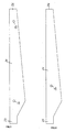
- FIG. 1 a simplified representation of the rotor blade 21 is shown.
- This rotor blade 21 has two through-holes 30, 32 in its longitudinal direction between the rotor blade root 25 and the rotor blade tip 26.
- the through-hole 32 is formed in the region of the rotor blade tip 26, while the through-hole 30 is located in the rotor blade rooting region. These positions are set so that a safe handling of the rotor blade is ensured when mounted on a rotor hub of a wind turbine.
- the determination of the position for the holes 30, 32 takes place in consideration of a connection to the supporting structure of the rotor blade 21.
- Fig. 2 shows a side view of the rotor blade 21 with only one through hole 30.
- This single through hole 30 is arranged in a meaningful manner in the center of gravity of the rotor blade, so that even with a handling means, the rotor blade is safely handled. Again, of course, a connection with the supporting structure is taken into account.
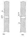
- FIGS. 3 and 4 By way of example, alternative embodiments of the through holes are shown.
- a cylindrical through hole 30, 32 is shown, which can be closed by suitable covers.
- Fig. 4 shows a through hole 30, 32, which is also cylindrical in a central portion, wherein the surfaces of the rotor blade 21 adjacent end portions of the through hole 30, 32 but widen.
- This broadening allows for improved attachment of covers that close the through-hole 30, 32 to prevent dirt and moisture from entering, and to inhibit flow of the rotor blade through the hole by being flush with the surface. It come to the attachment of such (not shown) cover different, known per se options, such. As an undercut, thread, etc.
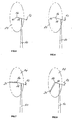
- Fig. 5 is the initial situation of the inventive method for attaching rotor blades on the rotor hub of a wind turbine shown.
- rotor blades with through holes as in Fig. 1 and 2 shown used.
- Figures 5-13 are the components required to explain the invention strong shown in simplified form.
- the reference numeral 10 denotes the tower of a wind turbine
- 12 indicates the orientation of the nacelle
- 14 represents the rotor circuit
- 16, 17 and 18 indicate the orientation of the rotor blade terminals
- 21, 22 and 23 denote mounted rotor blades.
- the through holes 30, 32 For mounting the rotor blades on the rotor hub of the nacelle of a wind turbine handling means in the through holes 30, 32 are fixed in order to be able to safely transport the rotor blades with them and with the aid of a crane up to the rotor hub. Since the through holes extend between the suction and the pressure side of the rotor blade, the rotor blades can be handled safely in a horizontal position. The provision of the through-holes in the rotor blades described above greatly simplifies the method of assembling these rotor blades described below.
- Fig. 5 is the rotor circuit 14 in the viewing direction behind the tower 10 of the wind turbine and the rotor blade terminals 16, 17, 18 are in the positions 12 clock, 4 clock and 8 clock.
- the rotor hub is now brought into a predetermined position. This is in Fig. 6 shown. It is essential that the rotor blade connection 17 is now in the 9 o'clock position. Accordingly, the rotor blade connection 16 is now in the 1 o'clock position and the rotor blade connection 18 is in the 5 o'clock position.
- Fig. 8 The next step is in Fig. 8 shown.
- the rotor blade 21 is lowered to the 7 o'clock position. This lowering can be done by gravity.
- the crane (not shown), which has lifted the rotor blade 21 to the mounting position, counteract the rotation and thus force a controlled rotation.
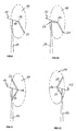
- Fig. 9 illustrates that with unchanged position of the rotor hub, the nacelle was rotated by 180 degrees, so that the rotor circuit 14 is in the direction of observation in front of the tower 10.
- the rotor blade 21 is now in the 5 o'clock position, the rotor blade connection 16 in the 1 o'clock position and the rotor blade connection 18 in the 9 o'clock position.
- a further rotor blade raised in a horizontal position by the crane can now be attached to this rotor blade connection 18 without the crane having to change its position.
- Fig. 10 The resulting situation is in Fig. 10 shown. There, the rotor blade connection 16 is still in the 1 o'clock position, the first rotor blade 21 in the 5 o'clock position, while the second rotor blade 22 is now shown in the 9 o'clock position.
- the rotor blade 21 is pivoted by means of the crane from the 5 o'clock position to the 7 o'clock position.
- the second rotor blade 22 reaches the 11 o'clock position and the rotor blade connection 16 reaches the 3 o'clock position.
- the gondola is again rotated 180 degrees.
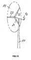
- Fig. 12 The result of this rotation is in Fig. 12 shown. From the perspective of the beholder, the rotor circuit 14 is now behind the tower 10. This is the same position of the rotor hub, the first rotor blade 21 in the 5 o'clock position, the second rotor blade 22 is in the 1 o'clock position and the rotor blade connection 16 is in the 9 o'clock position. Thus, can Again, without a location change of the crane, a third rotor blade are attached to this rotor blade connection 16. This is in the Fig. 13 shown. The first rotor blade 21 is in the 5 o'clock position, the second rotor blade 22 in the 1 o'clock position and the third rotor blade 23 in the 9 o'clock position. Thus, the inventive method is completed and all three rotor blades have been attached to the wind turbine.
Abstract
Description
Die vorliegende Erfindung betrifft ein Verfahren zur Montage von Rotorblättern an einer Rotornabe, die mit einer Gondel einer Windenergieanlage verbunden ist, wie im Oberbegriff von Anspruch 1 definiert wird. Ein solches Verfahren ist z.B. aus der
Rotorblätter für Windenergieanlagen sind allgemein bekannt. Mit zunehmender Größe der Windenergieanlagen und ansteigender Leistung nimmt auch die Größe der Rotorblätter sowie deren Eigengewicht zu. Zur Montage der Komponenten sind deshalb Kräne erforderlich, die Lasten mit höherem Eigengewicht in größere Höhen transportieren können. Demnach werden auch die benötigten Kräne größer.Rotor blades for wind turbines are well known. With increasing size of the wind turbines and increasing power and the size of the rotor blades and their own weight increases. To mount the components therefore cranes are required, which can transport loads with higher weight to higher altitudes. Accordingly, the required cranes are larger.
Aufgabe der Erfindung ist es, die Montage der Rotorblätter zu vereinfachen sowie die Handhabbarkeit der Rotorblätter zu verbessern.The object of the invention is to simplify the assembly of the rotor blades and to improve the handling of the rotor blades.
Die Aufgabe der Erfindung wird durch ein Verfahren zur Rotorblatt-Montage nach Anspruch 1.The object of the invention is achieved by a method for rotor blade assembly according to
Das Verfahren zur Montage von Rotorblättern an einer Rotornabe, welche mit einer Gondel einer Windenergieanlage verbunden ist, erfolgt durch Drehen der Rotornabe in eine vorgegebene erste Position, Anbringen eines Rotorblattes, Drehen der Rotornabe mit Hilfs des Rotorblattes in eine vorgegebene zweite Position, wobei die Drehung der Rotornabe in Richtung der Schwerkraftwirkung des bereits montierten ersten Rotorblattes erfolgt.The method for mounting rotor blades on a rotor hub, which is connected to a nacelle of a wind turbine, is done by rotating the rotor hub in a predetermined first position, attaching a rotor blade, rotating the rotor hub with auxiliary rotor blade in a predetermined second position, wherein the rotation the rotor hub takes place in the direction of the gravitational force of the already mounted first rotor blade.
Somit kann auch bei der Montage von Rotorblättern an Windenergieanlagen mit einer relativ großen Nabenhöhe ein Kran verwendet werden, der auch zur Montage der Rotornabe selbst bzw. der Gondel ausreicht.Thus, even with the assembly of rotor blades on wind turbines with a relatively large hub height, a crane can be used, which is also sufficient for mounting the rotor hub itself or the nacelle.
In einer besonders bevorzugten Weiterbildung des erfindungsgemäßen Verfahrens wird die Gondel um 180 Grad gedreht, bevor das zweite Rotorblatt angebracht wird. Diese Vorgehensweise gestattet die Montage des zweiten Rotorblattes, ohne dass der Kran seinen Standort verändern muss, da sich durch die Drehung der Gondel die Anbauposition des Rotorblattes wiederum an der Seite der Windenergieanlage befindet, an welcher der Kran aufgebaut istIn a particularly preferred embodiment of the method according to the invention, the nacelle is rotated by 180 degrees before the second rotor blade is attached. This procedure allows the assembly of the second rotor blade, without the crane having to change its location, since the mounting position of the rotor blade is in turn on the side of the wind turbine on which the crane is constructed by the rotation of the nacelle
In einer weiteren bevorzugten Weiterbildung des Verfahrens wird die Rotornabe mit Hilfe des zweiten Rotorblattes in eine weitere vorgegebene Position gedreht, die Gondel erneut um 180 Grad gedreht und ein drittes Rotorblatt 23 angebracht.In a further preferred embodiment of the method, the rotor hub is rotated by means of the second rotor blade in a further predetermined position, the nacelle rotated again by 180 degrees and attached to a
Auch diese Montage des dritten Rotorblattes ist ohne eine Änderung des Standortes des Kranes möglich und durch die Einsparung der aufwändigen Standortwechsel des Kranes lassen sich die Rotorblätter zeitsparend anbringen.This assembly of the third rotor blade is possible without a change in the location of the crane and by saving the time-consuming relocation of the crane, the rotor blades can install time-saving.
Um die Drehung der Nabe auf besonders einfache und wirkungsvolle Weise zu unterstützen, kann der Kran an dem Rotorblatt und insbesondere bevorzugt an einem Durchgangsloch des Rotorblattes angreifen und somit die Drehung des Rotorblattes in Richtung der Schwerkraft durch eine entgegengesetzt gerichtete Kraft verzögern. Dadurch kann die Drehung auf einfache Weise sicher kontrolliert und beeinflusst werden.In order to assist the rotation of the hub in a particularly simple and effective manner, the crane can engage the rotor blade and more preferably at a through-hole of the rotor blade and thus delay the rotation of the rotor blade in the direction of gravity by an oppositely directed force. As a result, the rotation can be easily controlled and influenced in a simple manner.
Um die Handhabbarkeit des Rotorblattes zu verbessern, weist das Rotorblatt wenigstens ein Durchgangsloch in dem Rotorblatt an einer vorgegebenen Position auf. Dies hat insbesondere den Vorteil, dass Handhabungsmittel, welche durch das Rotorblatt hindurch greifen können, in der Anwendung schneller und sicherer sind als die bekannte Handhabung mit Gurten und Zurrseilen.In order to improve the handling of the rotor blade, the rotor blade has at least one through hole in the rotor blade at a predetermined position. This has the particular advantage that handling means, which can reach through the rotor blade, are faster and safer to use than the known handling with straps and lashing cables.
Weitere vorteilhafte Ausführungsformen sind in den Unteransprüchen angegeben.Further advantageous embodiments are specified in the subclaims.
Im Folgenden wird die Erfindung anhand der Figuren näher beschrieben. Dabei zeigen;
- Fig. 1
- eine Seitenansicht eines Rotorblattes;
- Fig. 2
- eine Seitenansicht eines Rotorblattes;
- Fig, 3
- eine vereinfachte Querschnitts-Darstellung eines Rotorblatt-Abschnittes mit einem Durchgangsloch;
- Fig. 4
- eine vereinfachte Querschnitts-Darstellung eines Rotorblatt-Abschnittes mit einer alternativen Ausführungsform des Durchgangsloches;
- Fig. 5
- die Ausgangssituation bei dem erfindungsgemäßen Verfahren zur Montage des Rotorblattes;
- Fig. 6
- den ersten Schritt des erfindungsgemäßen Verfahrens;
- Fig. 7
- den zweiten Schritt des erfindungsgemäßen Verfahrens;
- Fig. 8
- den dritten Schritt des erfindungsgemäßen Verfahrens;
- Fig. 9
- den vierten Schritt des erfindungsgemäßen Verfahrens;
- Fig. 10
- den fünften Schritt des erfindungsgemäßen Verfahrens;
- Fig. 11
- den sechsten Schritt des erfindungsgemäßen Verfahrens;
- Fig. 12
- den siebten Schritt des erfindungsgemäßen Verfahrens; und
- Fig. 13
- den achten Schritt des erfindungsgemäßen Verfahrens.
- Fig. 1
- a side view of a rotor blade;
- Fig. 2
- a side view of a rotor blade;
- Fig. 3
- a simplified cross-sectional view of a rotor blade section with a through hole;
- Fig. 4
- a simplified cross-sectional view of a rotor blade section with an alternative embodiment of the through hole;
- Fig. 5
- the initial situation in the inventive method for mounting the rotor blade;
- Fig. 6
- the first step of the method according to the invention;
- Fig. 7
- the second step of the method according to the invention;
- Fig. 8
- the third step of the method according to the invention;
- Fig. 9
- the fourth step of the method according to the invention;
- Fig. 10
- the fifth step of the method according to the invention;
- Fig. 11
- the sixth step of the method according to the invention;
- Fig. 12
- the seventh step of the method according to the invention; and
- Fig. 13
- the eighth step of the method according to the invention.
In der Draufsicht in
Weitere Ausführungsformen mit mehr als zwei Durchgangslöchern sind ebenfalls möglich.Other embodiments with more than two through holes are also possible.
In den
In
In
Zur Montage der Rotorblätter an der Rotornabe der Gondel einer Windenergieanlage werden Handhabungsmittel in den Durchgangslöchern 30, 32 befestigt, um mit ihnen sowie mit Hilfe eines Kranes die Rotorblätter sicher nach oben zur Rotornabe befördern zu können. Da die Durchgangslöcher zwischen der Saug- und der Druckseite des Rotorblattes verlaufen, können die Rotorblätter in einer horizontalen Lage sicher gehandhabt werden. Das Vorsehen der oben beschriebenen Durchgangslöcher in den Rotorblättern vereinfacht das nachfolgend beschriebene Verfahren zur Montage dieser Rotorblätter erheblich.For mounting the rotor blades on the rotor hub of the nacelle of a wind turbine handling means in the through
In
In dem ersten Verfahrensschritt wird nun die Rotornabe in eine vorgegebene Position gebracht. Diese ist in
Durch die so erreichte Ausrichtung des Rotorblattanschlusses 17 ist es möglich, ein Rotorblatt 21 in einer horizontalen Ausrichtung an diesem Rotorblattanschluss anzubringen. Dazu wird die Rotornabe in der gewünschten Position arretiert. Diese Arretierung wird für die weitere Beschreibung vorausgesetzt und nicht mehr explizit erwähnt.By the thus achieved alignment of the
Die Situation nach der Montage des ersten Rotorblattes 21 ist in
Der nächste Verfahrensschritt ist in
Weiterhin ist in dieser Figur erkennbar, dass der Rotorblattanschluss 18 jetzt in der 3-Uhr-Position ist und der Rotorblattanschluss 16 befindet sich in der 11-Uhr-Position.Furthermore, it can be seen in this figure that the
- Die sich dann ergebende Situation ist in
Zur Vorbereitung der Montage des dritten Rotorblattes wird dann, wie in
Das Ergebnis dieser Drehung ist in
Claims (4)
- A method for mounting rotor blades on a rotor hub of a wind power installation, the rotor hub being connected to a nacelle, comprising the steps of:a) rotating the rotor hub to a predetermined first position,b) attaching a rotor blade (21),c) rotating the rotor hub with the aid of the first rotor blade (21) to a predetermined second position,d) mounting a second rotor blade (22),characterised in that
the rotation of the rotor hub takes place in the direction of the effect of gravitational force of the first rotor blade (21),
wherein the nacelle is rotated through 180 degrees before the second rotor blade (22) is attached. - A method according to claim 1,
characterised in thata) the rotor hub is rotated with the aid of the second rotor blade (22) to a further predetermined position,b) the nacelle is again rotated through 180 degrees, andc) a third rotor blade (23) is attached. - A method according to either claim 1 or claim 2,
characterised in that a crane engages a rotor blade (21, 22) and assists the rotation of the hub. - A method according to claim 3,
characterised in that the crane engages a through-hole (30, 32) of the rotor blade (21, 22).
Priority Applications (6)
| Application Number | Priority Date | Filing Date | Title |
|---|---|---|---|
| EP10185397.6A EP2273101B1 (en) | 2003-02-10 | 2004-01-20 | Assembly process for rotorblades of a wind turbine |
| SI200431386T SI1597477T1 (en) | 2003-02-10 | 2004-01-20 | Method for mounting rotor blades |
| EP10154694.3A EP2180180B1 (en) | 2003-02-10 | 2004-01-20 | Wind turbine blade with through holes for handling |
| DK10154694.3T DK2180180T3 (en) | 2003-02-10 | 2004-01-20 | Rotor blade for a wind power plant with through holes for handling |
| CY20101100390T CY1109999T1 (en) | 2003-02-10 | 2010-04-30 | METHOD FOR FITTING A WAY FORWARDS |
| CY20161100551T CY1117935T1 (en) | 2003-02-10 | 2016-06-17 | ROAD WING WITH DIFFERENT HANDS FOR OPERATION |
Applications Claiming Priority (3)
| Application Number | Priority Date | Filing Date | Title |
|---|---|---|---|
| DE10305543 | 2003-02-10 | ||
| DE10305543A DE10305543C5 (en) | 2003-02-10 | 2003-02-10 | Method for assembling rotor blades and a rotor blade for a wind energy plant |
| PCT/EP2004/000368 WO2004070203A2 (en) | 2003-02-10 | 2004-01-20 | Method for mounting rotor blades and rotor blade for a wind turbine |
Related Child Applications (2)
| Application Number | Title | Priority Date | Filing Date |
|---|---|---|---|
| EP10154694.3A Division EP2180180B1 (en) | 2003-02-10 | 2004-01-20 | Wind turbine blade with through holes for handling |
| EP10154694.3 Division-Into | 2010-02-25 |
Publications (2)
| Publication Number | Publication Date |
|---|---|
| EP1597477A2 EP1597477A2 (en) | 2005-11-23 |
| EP1597477B1 true EP1597477B1 (en) | 2010-04-14 |
Family
ID=32747712
Family Applications (3)
| Application Number | Title | Priority Date | Filing Date |
|---|---|---|---|
| EP10185397.6A Expired - Lifetime EP2273101B1 (en) | 2003-02-10 | 2004-01-20 | Assembly process for rotorblades of a wind turbine |
| EP04703365A Expired - Lifetime EP1597477B1 (en) | 2003-02-10 | 2004-01-20 | Method for mounting rotor blades |
| EP10154694.3A Expired - Lifetime EP2180180B1 (en) | 2003-02-10 | 2004-01-20 | Wind turbine blade with through holes for handling |
Family Applications Before (1)
| Application Number | Title | Priority Date | Filing Date |
|---|---|---|---|
| EP10185397.6A Expired - Lifetime EP2273101B1 (en) | 2003-02-10 | 2004-01-20 | Assembly process for rotorblades of a wind turbine |
Family Applications After (1)
| Application Number | Title | Priority Date | Filing Date |
|---|---|---|---|
| EP10154694.3A Expired - Lifetime EP2180180B1 (en) | 2003-02-10 | 2004-01-20 | Wind turbine blade with through holes for handling |
Country Status (20)
| Country | Link |
|---|---|
| US (1) | US7353603B2 (en) |
| EP (3) | EP2273101B1 (en) |
| JP (2) | JP4335214B2 (en) |
| KR (2) | KR100751383B1 (en) |
| CN (2) | CN100447405C (en) |
| AR (1) | AR043122A1 (en) |
| AT (1) | ATE464476T1 (en) |
| AU (2) | AU2004209032B2 (en) |
| BR (1) | BRPI0407109B1 (en) |
| CA (1) | CA2515082C (en) |
| CY (3) | CY1109999T1 (en) |
| DE (2) | DE10305543C5 (en) |
| DK (3) | DK2273101T3 (en) |
| ES (3) | ES2570978T3 (en) |
| HU (1) | HUE028646T2 (en) |
| NZ (2) | NZ541554A (en) |
| PL (2) | PL219722B1 (en) |
| PT (2) | PT2273101E (en) |
| SI (3) | SI2273101T1 (en) |
| WO (1) | WO2004070203A2 (en) |
Cited By (2)
| Publication number | Priority date | Publication date | Assignee | Title |
|---|---|---|---|---|
| DE102019106969A1 (en) * | 2019-03-19 | 2020-09-24 | Wobben Properties Gmbh | Method for assembling rotor blades of a wind turbine |
| EP3805553A1 (en) | 2019-10-08 | 2021-04-14 | Wobben Properties GmbH | Method and device for installing rotor blades of a wind turbine |
Families Citing this family (51)
| Publication number | Priority date | Publication date | Assignee | Title |
|---|---|---|---|---|
| CA2554505C (en) | 2004-01-26 | 2010-04-27 | Vestas Wind Systems A/S | Methods of handling and manufacturing a wind turbine blade, handling system, wind turbine blade, handling means and use hereof |
| DK200501312A (en) | 2005-09-21 | 2007-03-22 | Lm Glasfiber As | Wing fasteners |
| DE102006008428B4 (en) * | 2006-02-23 | 2013-07-18 | Repower Systems Ag | Assembly / disassembly of a rotor blade |
| ATE471909T1 (en) * | 2006-11-23 | 2010-07-15 | Siemens Ag | METHOD AND DEVICE FOR MOUNTING WIND TURBINE BLADES |
| EP1925582B1 (en) * | 2006-11-23 | 2010-06-23 | Siemens Aktiengesellschaft | Method and a device for mounting of wind turbine blades |
| CN101971481B (en) * | 2007-11-05 | 2014-04-09 | 托马斯·斯图尔特·贝尔纳茨 | Horizontal axis wind turbine rotor assembly with lifting body rotor blades |
| GB0818466D0 (en) * | 2008-10-08 | 2008-11-12 | Blade Dynamics Ltd | A wind turbine rotor |
| EP2409020A2 (en) * | 2009-03-19 | 2012-01-25 | Technip France | Offshore wind turbine installation system and method |
| EP2345811B1 (en) * | 2010-01-14 | 2012-10-03 | Siemens Aktiengesellschaft | Clamp for clamping a blade for a wind turbine and method of installing wind turbine blades |
| JP4547039B1 (en) * | 2010-02-23 | 2010-09-22 | 株式会社日本製鋼所 | Installation method of rotor blade for wind power generation |
| DE202010015616U1 (en) * | 2010-11-18 | 2012-03-01 | Liebherr-Werk Ehingen Gmbh | crane |
| EP2377674A1 (en) * | 2010-04-16 | 2011-10-19 | Siemens Aktiengesellschaft | Method for manufacturing a wind turbine rotor blade and wind turbine rotor blade |
| US8562302B2 (en) * | 2010-07-06 | 2013-10-22 | General Electric Company | Wind turbine blade with integrated handling mechanism attachment bores |
| ES2640872T3 (en) * | 2010-09-15 | 2017-11-07 | Vestas Wind Systems A/S | Wind turbine blade structures, lifting assemblies and blade handling methods |
| EP2431970A1 (en) | 2010-09-21 | 2012-03-21 | Fraunhofer-Gesellschaft zur Förderung der Angewandten Forschung e.V. | Watermark generator, watermark decoder, method for providing a watermarked signal based on discrete valued data and method for providing discrete valued data in dependence on a watermarked signal |
| EP2453129B8 (en) * | 2010-11-11 | 2014-11-19 | ALSTOM Renewable Technologies | Blade for a wind turbine |
| US8240993B2 (en) * | 2011-01-04 | 2012-08-14 | General Electric Company | System and method of manipulating a boundary layer across a rotor blade of a wind turbine |
| WO2012148012A1 (en) * | 2011-04-26 | 2012-11-01 | 주식회사 포스코건설 | Rotor blade for a tidal power generating turbine and method for manufacturing same |
| DE102011017801B8 (en) | 2011-04-29 | 2013-05-08 | Wobben Properties Gmbh | Wind turbine with a plurality of displacement units for mounting or dismounting of rotor blades and method thereof |
| DK2715112T3 (en) | 2011-05-27 | 2016-02-08 | Vestas Wind Sys As | DEVICE FOR MANIPULATING A WINDMILL EXERCISE AND PROCEDURE FOR WING MANAGEMENT |
| DE102011076937B3 (en) | 2011-06-03 | 2012-12-06 | Aloys Wobben | Wind turbine rotor blade and method of assembling a wind turbine rotor blade |
| DE102011116189B3 (en) * | 2011-06-21 | 2012-10-04 | Repower Systems Se | Load handling device for raising rotor blade of wind energy plant to mounting position, has support assembly having supporting surface projected in vertical plane to make contact of rotor blade or attaching element with support assembly |
| DK2573384T3 (en) | 2011-09-21 | 2017-07-03 | Siemens Ag | Method for rotating the rotor of a wind turbine and means for use in this method |
| EP2573385A1 (en) | 2011-09-22 | 2013-03-27 | Siemens Aktiengesellschaft | Method to rotate the rotor of a wind turbine and means to use in this method |
| EP2574774B1 (en) | 2011-09-27 | 2014-08-06 | Siemens Aktiengesellschaft | Method to rotate the rotor of a wind turbine and means to use in this method |
| DE102011084140A1 (en) | 2011-10-07 | 2013-04-11 | Wobben Properties Gmbh | Method and device for mounting a rotor of a wind energy plant |
| DK2589795T3 (en) | 2011-11-04 | 2015-03-30 | Siemens Ag | Lifting frame for lifting a wind turbine rotor blade and the method of mounting vindmøllerotorvinger |
| EP2607684B1 (en) | 2011-12-19 | 2015-04-01 | Siemens Aktiengesellschaft | Means to rotate the rotor of a wind turbine and method to rotate the rotor |
| EP2617987B1 (en) | 2012-01-20 | 2014-04-30 | Siemens Aktiengesellschaft | Method and arrangement for installing a rotor blade |
| DK2617986T3 (en) | 2012-01-20 | 2014-05-19 | Siemens Ag | Method and device for mounting a rotor blade |
| EP2650537B1 (en) * | 2012-04-11 | 2014-12-31 | Siemens Aktiengesellschaft | A counter weight arrangement to balance out and align a partially mounted rotor of a wind turbine and method thereof |
| KR101380663B1 (en) * | 2012-06-28 | 2014-04-04 | 삼성중공업 주식회사 | Blade repairing method and Binding apparatus of safety ring |
| KR101400205B1 (en) * | 2013-02-06 | 2014-05-27 | 삼성중공업 주식회사 | Balancing device and method for mounting wind turbine blade using the same |
| DK2767708T3 (en) | 2013-02-13 | 2015-08-10 | Siemens Ag | Turning device for rotating the rotatable part of a wind turbine |
| DE102013211751A1 (en) | 2013-06-21 | 2014-12-24 | Wobben Properties Gmbh | Method for mounting a wind turbine rotor blade and wind turbine rotor blade |
| US10113530B2 (en) | 2014-02-20 | 2018-10-30 | General Electric Company | Methods and systems for removing and/or installing wind turbine rotor blades |
| US9638163B2 (en) | 2014-02-20 | 2017-05-02 | General Electric Company | Methods and systems for removing and/or installing wind turbine rotor blades |
| US9651021B2 (en) | 2014-09-09 | 2017-05-16 | General Electric Company | System and method for removing and/or installing a rotor blade of a wind turbine |
| US9821417B2 (en) | 2015-05-07 | 2017-11-21 | General Electric Company | System and method for replacing a pitch bearing |
| US9890022B2 (en) | 2015-05-07 | 2018-02-13 | General Electric Company | Method for suspending a rotor blade from a hub of a wind turbine |
| JP6546803B2 (en) * | 2015-07-22 | 2019-07-17 | 株式会社日立製作所 | Wind turbine generator and wireless communication method in wind turbine generator |
| US10066601B2 (en) | 2015-10-22 | 2018-09-04 | General Electric Company | System and method for manufacturing wind turbine rotor blades for simplified installation and removal |
| ES2792026T3 (en) | 2015-12-22 | 2020-11-06 | Vestas Wind Sys As | Methods for assembling or disassembling wind turbine components of a multi-rotor wind turbine |
| DE102016110747A1 (en) | 2016-06-10 | 2017-12-14 | Wobben Properties Gmbh | Rotor blade, wind energy plant and method for assembling and producing a rotor blade |
| WO2018113878A1 (en) | 2016-12-21 | 2018-06-28 | Vestas Wind Systems A/S | Wind turbine service or construction method and apparatus |
| US10508645B2 (en) | 2017-07-17 | 2019-12-17 | General Electric Company | System and method for suspending a rotor blade of a wind turbine uptower |
| ES2918591T3 (en) | 2017-08-31 | 2022-07-19 | Gen Electric | Procedure and tool for removing a pitch bearing from a wind turbine hub |
| DK179738B1 (en) | 2017-10-11 | 2019-04-30 | Ravn Niels | Wind-Driven Energy Converting Device |
| EP3617498B1 (en) * | 2018-08-29 | 2022-07-20 | General Electric Renovables España S.L. | Methods of rotating a hub of a wind turbine |
| CN112664392A (en) | 2019-10-15 | 2021-04-16 | 通用电气公司 | System and method for locking wind turbine rotor during extended maintenance |
| EP3845758B1 (en) * | 2019-12-31 | 2023-10-11 | Nordex Energy Spain, S.A.U. | Blade assembly method on a rotor hub of a wind turbine |
Family Cites Families (18)
| Publication number | Priority date | Publication date | Assignee | Title |
|---|---|---|---|---|
| GB452611A (en) * | 1935-08-24 | 1936-08-26 | Charles Richard Fairey | Improvements in metal airscrews |
| US4008817A (en) * | 1972-02-18 | 1977-02-22 | United States Steel Corporation | Saw blade handling device |
| US4439108A (en) * | 1982-06-08 | 1984-03-27 | Richard Will | Windmill having centrifically feathered rotors to control rotor speed |
| JPH01182285A (en) * | 1987-12-29 | 1989-07-20 | Nkk Corp | Method for improving earthquake-resistance of elevated tank |
| JPH02112700A (en) * | 1988-10-19 | 1990-04-25 | Fujitsu Ltd | Blade construction in axial flow fan |
| IT219392Z2 (en) * | 1990-03-12 | 1993-02-26 | FIXING SYSTEM BETWEEN EXTRUDED BUCKET WITH HOLLOW STRUCTURE FOR AXIAL FAN AND BUCKET LEG INSERTED | |
| JPH06193550A (en) * | 1992-12-25 | 1994-07-12 | Ishikawajima Harima Heavy Ind Co Ltd | Fixing method for rotary vane for wind power generation device |
| CN2228557Y (en) * | 1995-08-10 | 1996-06-05 | 邓宏博 | Vehicle type horizontal-rotation wind-driven generator |
| JP3700306B2 (en) * | 1997-01-27 | 2005-09-28 | Jfeエンジニアリング株式会社 | Wind power generator construction method |
| JPH1182285A (en) * | 1997-09-16 | 1999-03-26 | Nkk Corp | Construction method of wind power generator, climbing crane device, and maintenance using the same |
| DK173530B2 (en) * | 1999-11-17 | 2005-07-18 | Siemens Wind Power As | Method for mounting main components in a wind turbine cabin and such a wind turbine cabin |
| US6364609B1 (en) | 2000-05-01 | 2002-04-02 | Robert J. Barnes | Wind turbine having ground winch pivot erection support structure |
| WO2001094249A1 (en) * | 2000-06-06 | 2001-12-13 | Demag Mobile Cranes Gmbh | Method and device for mounting a wind turbine |
| DE10031473C1 (en) * | 2000-06-28 | 2002-02-28 | Tacke Windenergie Gmbh | Device for rotating a shaft of a wind power plant connected or coupled to a rotor |
| DE10141928B4 (en) * | 2001-07-20 | 2004-04-15 | Wobben, Aloys, Dipl.-Ing. | Method for assembling a wind turbine |
| DE10262308B4 (en) * | 2002-01-08 | 2009-02-05 | Aloys Wobben | Device for handling piece goods |
| BR0215738B1 (en) * | 2002-05-27 | 2011-12-27 | Methods for handling wind turbine blades and mounting said blades on a wind turbine, gripping system and unit for handling a wind turbine blade. | |
| DE10225025A1 (en) * | 2002-06-06 | 2003-12-24 | Aloys Wobben | Device for handling rotor blades |
-
2003
- 2003-02-10 DE DE10305543A patent/DE10305543C5/en not_active Expired - Fee Related
-
2004
- 2004-01-20 CN CNB2004800035255A patent/CN100447405C/en not_active Expired - Fee Related
- 2004-01-20 ES ES10154694T patent/ES2570978T3/en not_active Expired - Lifetime
- 2004-01-20 ES ES10185397T patent/ES2426103T3/en not_active Expired - Lifetime
- 2004-01-20 PT PT101853976T patent/PT2273101E/en unknown
- 2004-01-20 HU HUE10154694A patent/HUE028646T2/en unknown
- 2004-01-20 PT PT04703365T patent/PT1597477E/en unknown
- 2004-01-20 CN CN2007101234779A patent/CN101070814B/en not_active Expired - Fee Related
- 2004-01-20 DK DK10185397.6T patent/DK2273101T3/en active
- 2004-01-20 NZ NZ541554A patent/NZ541554A/en not_active IP Right Cessation
- 2004-01-20 CA CA002515082A patent/CA2515082C/en not_active Expired - Fee Related
- 2004-01-20 ES ES04703365T patent/ES2341542T3/en not_active Expired - Lifetime
- 2004-01-20 AU AU2004209032A patent/AU2004209032B2/en not_active Ceased
- 2004-01-20 KR KR1020057014695A patent/KR100751383B1/en active IP Right Grant
- 2004-01-20 DE DE502004011037T patent/DE502004011037D1/en not_active Expired - Lifetime
- 2004-01-20 BR BRPI0407109-3A patent/BRPI0407109B1/en not_active IP Right Cessation
- 2004-01-20 PL PL401585A patent/PL219722B1/en unknown
- 2004-01-20 DK DK10154694.3T patent/DK2180180T3/en active
- 2004-01-20 PL PL376660A patent/PL216992B1/en unknown
- 2004-01-20 EP EP10185397.6A patent/EP2273101B1/en not_active Expired - Lifetime
- 2004-01-20 NZ NZ582987A patent/NZ582987A/en not_active IP Right Cessation
- 2004-01-20 EP EP04703365A patent/EP1597477B1/en not_active Expired - Lifetime
- 2004-01-20 AT AT04703365T patent/ATE464476T1/en active
- 2004-01-20 US US10/544,473 patent/US7353603B2/en not_active Expired - Lifetime
- 2004-01-20 SI SI200432073T patent/SI2273101T1/en unknown
- 2004-01-20 KR KR1020077006132A patent/KR100945128B1/en active IP Right Grant
- 2004-01-20 SI SI200431386T patent/SI1597477T1/en unknown
- 2004-01-20 JP JP2005518351A patent/JP4335214B2/en not_active Expired - Lifetime
- 2004-01-20 SI SI200432315A patent/SI2180180T1/en unknown
- 2004-01-20 DK DK04703365.9T patent/DK1597477T3/en active
- 2004-01-20 EP EP10154694.3A patent/EP2180180B1/en not_active Expired - Lifetime
- 2004-01-20 WO PCT/EP2004/000368 patent/WO2004070203A2/en active Search and Examination
- 2004-02-06 AR ARP040100387A patent/AR043122A1/en not_active Application Discontinuation
-
2008
- 2008-05-19 JP JP2008131193A patent/JP4856117B2/en not_active Expired - Lifetime
- 2008-09-30 AU AU2008229709A patent/AU2008229709A1/en not_active Abandoned
-
2010
- 2010-04-30 CY CY20101100390T patent/CY1109999T1/en unknown
-
2013
- 2013-10-15 CY CY20131100900T patent/CY1114494T1/en unknown
-
2016
- 2016-06-17 CY CY20161100551T patent/CY1117935T1/en unknown
Cited By (5)
| Publication number | Priority date | Publication date | Assignee | Title |
|---|---|---|---|---|
| DE102019106969A1 (en) * | 2019-03-19 | 2020-09-24 | Wobben Properties Gmbh | Method for assembling rotor blades of a wind turbine |
| WO2020187959A1 (en) | 2019-03-19 | 2020-09-24 | Wobben Properties Gmbh | Method for installing rotor blades of a wind turbine |
| US11933266B2 (en) | 2019-03-19 | 2024-03-19 | Wobben Properties Gmbh | Method for installing rotor blades of a wind turbine |
| EP3805553A1 (en) | 2019-10-08 | 2021-04-14 | Wobben Properties GmbH | Method and device for installing rotor blades of a wind turbine |
| US11692529B2 (en) | 2019-10-08 | 2023-07-04 | Wobben Properties Gmbh | Method for mounting rotor blades of a wind turbine |
Also Published As
Similar Documents
| Publication | Publication Date | Title |
|---|---|---|
| EP1597477B1 (en) | Method for mounting rotor blades | |
| DE10201726B4 (en) | Wind turbine | |
| DE2756071C2 (en) | ||
| DE102006031174B3 (en) | Wind power plant rotor hub for rotor, has rotor blade, where hub core body and hub external body are connected by flange connection, where flange connection with pre-determined inclination is designed as rotational axis of rotor | |
| DE10324166B4 (en) | Rotor blade connection | |
| EP2420670B1 (en) | Rotor locking device and method for arresting a rotor of a wind energy assembly | |
| EP2368037A2 (en) | Locking device for a rotor of a wind turbines | |
| EP3710694A1 (en) | Flange frame and assembly set for pre-assembling and/or transporting and/or assembling a tower segment for a wind turbine, and method | |
| EP3805553B1 (en) | Method and device for installing rotor blades of a wind turbine | |
| WO1996013668A1 (en) | Radial compressor or radial turbine with a turbine nozzle ring or diffuser comprising guide vanes | |
| DE102009007812B4 (en) | Wind turbine with wind-slip profiling | |
| EP3844384A1 (en) | Rotor blade, wind turbine, and method for optimising a wind turbine | |
| EP3698041B1 (en) | Rotor blade and rotor for a wind turbine, having bearing-free pitch adjustment, and wind turbine | |
| AT392124B (en) | WIND WHEEL WING | |
| EP3431749B1 (en) | Extender for fixing a rotor blade to a rotor hub housing of a wind turbine, method for producing an extender and method for mounting an extender | |
| EP3969740B1 (en) | Wind turbine and wind turbine rotor blade | |
| EP3511561B1 (en) | Wind turbine, holder and rotor blade for a wind turbine | |
| EP3587800B1 (en) | Support system for a spinner of a rotor hub for a wind turbine | |
| EP3626964B1 (en) | Modular retaining system for transporting a rotor blade of a wind turbine and transport frame | |
| WO2002095221A1 (en) | Kinetic energy installation, in particular a wind energy installation |
Legal Events
| Date | Code | Title | Description |
|---|---|---|---|
| PUAI | Public reference made under article 153(3) epc to a published international application that has entered the european phase |
Free format text: ORIGINAL CODE: 0009012 |
|
| 17P | Request for examination filed |
Effective date: 20050912 |
|
| AK | Designated contracting states |
Kind code of ref document: A2 Designated state(s): AT BE BG CH CY CZ DE DK EE ES FI FR GB GR HU IE IT LI LU MC NL PT RO SE SI SK TR |
|
| AX | Request for extension of the european patent |
Extension state: AL LT LV MK |
|
| DAX | Request for extension of the european patent (deleted) | ||
| 17Q | First examination report despatched |
Effective date: 20080122 |
|
| GRAP | Despatch of communication of intention to grant a patent |
Free format text: ORIGINAL CODE: EPIDOSNIGR1 |
|
| GRAC | Information related to communication of intention to grant a patent modified |
Free format text: ORIGINAL CODE: EPIDOSCIGR1 |
|
| RTI1 | Title (correction) |
Free format text: METHOD FOR MOUNTING ROTOR BLADES |
|
| GRAS | Grant fee paid |
Free format text: ORIGINAL CODE: EPIDOSNIGR3 |
|
| GRAA | (expected) grant |
Free format text: ORIGINAL CODE: 0009210 |
|
| AK | Designated contracting states |
Kind code of ref document: B1 Designated state(s): AT BE BG CH CY CZ DE DK EE ES FI FR GB GR HU IE IT LI LU MC NL PT RO SE SI SK TR |
|
| REG | Reference to a national code |
Ref country code: GB Ref legal event code: FG4D Free format text: NOT ENGLISH |
|
| REG | Reference to a national code |
Ref country code: CH Ref legal event code: EP |
|
| REG | Reference to a national code |
Ref country code: IE Ref legal event code: FG4D Free format text: LANGUAGE OF EP DOCUMENT: GERMAN |
|
| REG | Reference to a national code |
Ref country code: GR Ref legal event code: EP Ref document number: 20100400994 Country of ref document: GR |
|
| REG | Reference to a national code |
Ref country code: PT Ref legal event code: SC4A Free format text: AVAILABILITY OF NATIONAL TRANSLATION Effective date: 20100519 |
|
| REF | Corresponds to: |
Ref document number: 502004011037 Country of ref document: DE Date of ref document: 20100527 Kind code of ref document: P |
|
| REG | Reference to a national code |
Ref country code: CH Ref legal event code: NV Representative=s name: ZIMMERLI, WAGNER & PARTNER AG |
|
| REG | Reference to a national code |
Ref country code: ES Ref legal event code: FG2A Ref document number: 2341542 Country of ref document: ES Kind code of ref document: T3 |
|
| REG | Reference to a national code |
Ref country code: DK Ref legal event code: T3 |
|
| REG | Reference to a national code |
Ref country code: RO Ref legal event code: EPE |
|
| REG | Reference to a national code |
Ref country code: SE Ref legal event code: TRGR |
|
| REG | Reference to a national code |
Ref country code: NL Ref legal event code: T3 |
|
| REG | Reference to a national code |
Ref country code: SK Ref legal event code: T3 Ref document number: E 7402 Country of ref document: SK |
|
| REG | Reference to a national code |
Ref country code: HU Ref legal event code: AG4A Ref document number: E008276 Country of ref document: HU |
|
| PLBE | No opposition filed within time limit |
Free format text: ORIGINAL CODE: 0009261 |
|
| STAA | Information on the status of an ep patent application or granted ep patent |
Free format text: STATUS: NO OPPOSITION FILED WITHIN TIME LIMIT |
|
| 26N | No opposition filed |
Effective date: 20110117 |
|
| PG25 | Lapsed in a contracting state [announced via postgrant information from national office to epo] |
Ref country code: MC Free format text: LAPSE BECAUSE OF NON-PAYMENT OF DUE FEES Effective date: 20110131 |
|
| REG | Reference to a national code |
Ref country code: CH Ref legal event code: NV Representative=s name: WAGNER PATENT AG, CH |
|
| REG | Reference to a national code |
Ref country code: FR Ref legal event code: PLFP Year of fee payment: 13 |
|
| REG | Reference to a national code |
Ref country code: FR Ref legal event code: PLFP Year of fee payment: 14 |
|
| REG | Reference to a national code |
Ref country code: FR Ref legal event code: PLFP Year of fee payment: 15 |
|
| PGFP | Annual fee paid to national office [announced via postgrant information from national office to epo] |
Ref country code: LU Payment date: 20180124 Year of fee payment: 15 |
|
| PGFP | Annual fee paid to national office [announced via postgrant information from national office to epo] |
Ref country code: CH Payment date: 20180125 Year of fee payment: 15 Ref country code: FI Payment date: 20180119 Year of fee payment: 15 Ref country code: RO Payment date: 20180109 Year of fee payment: 15 Ref country code: CZ Payment date: 20180105 Year of fee payment: 15 |
|
| PGFP | Annual fee paid to national office [announced via postgrant information from national office to epo] |
Ref country code: PL Payment date: 20180213 Year of fee payment: 15 Ref country code: GR Payment date: 20180123 Year of fee payment: 15 Ref country code: BE Payment date: 20180124 Year of fee payment: 15 Ref country code: EE Payment date: 20180124 Year of fee payment: 15 Ref country code: SK Payment date: 20180108 Year of fee payment: 15 Ref country code: TR Payment date: 20180117 Year of fee payment: 15 Ref country code: IE Payment date: 20180125 Year of fee payment: 15 Ref country code: HU Payment date: 20180111 Year of fee payment: 15 Ref country code: BG Payment date: 20180124 Year of fee payment: 15 Ref country code: IT Payment date: 20180126 Year of fee payment: 15 |
|
| PGFP | Annual fee paid to national office [announced via postgrant information from national office to epo] |
Ref country code: CY Payment date: 20180118 Year of fee payment: 15 |
|
| REG | Reference to a national code |
Ref country code: EE Ref legal event code: MM4A Ref document number: E004247 Country of ref document: EE Effective date: 20190131 |
|
| REG | Reference to a national code |
Ref country code: CH Ref legal event code: PL |
|
| PG25 | Lapsed in a contracting state [announced via postgrant information from national office to epo] |
Ref country code: LU Free format text: LAPSE BECAUSE OF NON-PAYMENT OF DUE FEES Effective date: 20190120 |
|
| REG | Reference to a national code |
Ref country code: SK Ref legal event code: MM4A Ref document number: E 7402 Country of ref document: SK Effective date: 20190120 |
|
| REG | Reference to a national code |
Ref country code: BE Ref legal event code: MM Effective date: 20190131 |
|
| REG | Reference to a national code |
Ref country code: SI Ref legal event code: KO00 Effective date: 20190927 Ref country code: IE Ref legal event code: MM4A |
|
| PG25 | Lapsed in a contracting state [announced via postgrant information from national office to epo] |
Ref country code: SI Free format text: LAPSE BECAUSE OF NON-PAYMENT OF DUE FEES Effective date: 20190121 Ref country code: RO Free format text: LAPSE BECAUSE OF NON-PAYMENT OF DUE FEES Effective date: 20190120 Ref country code: CZ Free format text: LAPSE BECAUSE OF NON-PAYMENT OF DUE FEES Effective date: 20190120 Ref country code: EE Free format text: LAPSE BECAUSE OF NON-PAYMENT OF DUE FEES Effective date: 20190131 Ref country code: SK Free format text: LAPSE BECAUSE OF NON-PAYMENT OF DUE FEES Effective date: 20190120 Ref country code: FI Free format text: LAPSE BECAUSE OF NON-PAYMENT OF DUE FEES Effective date: 20190120 Ref country code: CY Free format text: LAPSE BECAUSE OF NON-PAYMENT OF DUE FEES Effective date: 20190120 |
|
| PG25 | Lapsed in a contracting state [announced via postgrant information from national office to epo] |
Ref country code: HU Free format text: LAPSE BECAUSE OF NON-PAYMENT OF DUE FEES Effective date: 20190121 Ref country code: BG Free format text: LAPSE BECAUSE OF NON-PAYMENT OF DUE FEES Effective date: 20190731 Ref country code: BE Free format text: LAPSE BECAUSE OF NON-PAYMENT OF DUE FEES Effective date: 20190131 Ref country code: GR Free format text: LAPSE BECAUSE OF NON-PAYMENT OF DUE FEES Effective date: 20190802 |
|
| PG25 | Lapsed in a contracting state [announced via postgrant information from national office to epo] |
Ref country code: LI Free format text: LAPSE BECAUSE OF NON-PAYMENT OF DUE FEES Effective date: 20190131 Ref country code: CH Free format text: LAPSE BECAUSE OF NON-PAYMENT OF DUE FEES Effective date: 20190131 |
|
| PG25 | Lapsed in a contracting state [announced via postgrant information from national office to epo] |
Ref country code: IE Free format text: LAPSE BECAUSE OF NON-PAYMENT OF DUE FEES Effective date: 20190120 |
|
| PG25 | Lapsed in a contracting state [announced via postgrant information from national office to epo] |
Ref country code: IT Free format text: LAPSE BECAUSE OF NON-PAYMENT OF DUE FEES Effective date: 20190120 |
|
| PGFP | Annual fee paid to national office [announced via postgrant information from national office to epo] |
Ref country code: ES Payment date: 20200219 Year of fee payment: 17 Ref country code: AT Payment date: 20200121 Year of fee payment: 17 Ref country code: PT Payment date: 20200110 Year of fee payment: 17 Ref country code: SE Payment date: 20200127 Year of fee payment: 17 |
|
| PGFP | Annual fee paid to national office [announced via postgrant information from national office to epo] |
Ref country code: DK Payment date: 20210120 Year of fee payment: 18 |
|
| REG | Reference to a national code |
Ref country code: SE Ref legal event code: EUG |
|
| REG | Reference to a national code |
Ref country code: AT Ref legal event code: MM01 Ref document number: 464476 Country of ref document: AT Kind code of ref document: T Effective date: 20210120 |
|
| PG25 | Lapsed in a contracting state [announced via postgrant information from national office to epo] |
Ref country code: AT Free format text: LAPSE BECAUSE OF NON-PAYMENT OF DUE FEES Effective date: 20210120 |
|
| PG25 | Lapsed in a contracting state [announced via postgrant information from national office to epo] |
Ref country code: PT Free format text: LAPSE BECAUSE OF NON-PAYMENT OF DUE FEES Effective date: 20210720 Ref country code: SE Free format text: LAPSE BECAUSE OF NON-PAYMENT OF DUE FEES Effective date: 20210121 |
|
| REG | Reference to a national code |
Ref country code: ES Ref legal event code: FD2A Effective date: 20220426 |
|
| PG25 | Lapsed in a contracting state [announced via postgrant information from national office to epo] |
Ref country code: TR Free format text: LAPSE BECAUSE OF NON-PAYMENT OF DUE FEES Effective date: 20190120 |
|
| PG25 | Lapsed in a contracting state [announced via postgrant information from national office to epo] |
Ref country code: ES Free format text: LAPSE BECAUSE OF NON-PAYMENT OF DUE FEES Effective date: 20210121 |
|
| REG | Reference to a national code |
Ref country code: DK Ref legal event code: EBP Effective date: 20220131 |
|
| PG25 | Lapsed in a contracting state [announced via postgrant information from national office to epo] |
Ref country code: DK Free format text: LAPSE BECAUSE OF NON-PAYMENT OF DUE FEES Effective date: 20220131 |
|
| PGFP | Annual fee paid to national office [announced via postgrant information from national office to epo] |
Ref country code: FR Payment date: 20230123 Year of fee payment: 20 |
|
| PGFP | Annual fee paid to national office [announced via postgrant information from national office to epo] |
Ref country code: GB Payment date: 20230124 Year of fee payment: 20 Ref country code: DE Payment date: 20220629 Year of fee payment: 20 |
|
| PGFP | Annual fee paid to national office [announced via postgrant information from national office to epo] |
Ref country code: NL Payment date: 20230124 Year of fee payment: 20 |
|
| REG | Reference to a national code |
Ref country code: DE Ref legal event code: R071 Ref document number: 502004011037 Country of ref document: DE |
|
| REG | Reference to a national code |
Ref country code: NL Ref legal event code: MK Effective date: 20240119 |
|
| REG | Reference to a national code |
Ref country code: GB Ref legal event code: PE20 Expiry date: 20240119 |