EP3805553A1 - Method and device for installing rotor blades of a wind turbine - Google Patents
Method and device for installing rotor blades of a wind turbine Download PDFInfo
- Publication number
- EP3805553A1 EP3805553A1 EP20199857.2A EP20199857A EP3805553A1 EP 3805553 A1 EP3805553 A1 EP 3805553A1 EP 20199857 A EP20199857 A EP 20199857A EP 3805553 A1 EP3805553 A1 EP 3805553A1
- Authority
- EP
- European Patent Office
- Prior art keywords
- rotor blade
- rotor
- mounting arm
- section
- hub
- Prior art date
- Legal status (The legal status is an assumption and is not a legal conclusion. Google has not performed a legal analysis and makes no representation as to the accuracy of the status listed.)
- Granted
Links
- 238000000034 method Methods 0.000 title claims abstract description 13
- 238000009434 installation Methods 0.000 claims abstract description 28
- 230000005484 gravity Effects 0.000 description 4
- 229910000831 Steel Inorganic materials 0.000 description 1
- 230000008878 coupling Effects 0.000 description 1
- 238000010168 coupling process Methods 0.000 description 1
- 238000005859 coupling reaction Methods 0.000 description 1
- 239000010959 steel Substances 0.000 description 1
Images


Classifications
-
- F—MECHANICAL ENGINEERING; LIGHTING; HEATING; WEAPONS; BLASTING
- F03—MACHINES OR ENGINES FOR LIQUIDS; WIND, SPRING, OR WEIGHT MOTORS; PRODUCING MECHANICAL POWER OR A REACTIVE PROPULSIVE THRUST, NOT OTHERWISE PROVIDED FOR
- F03D—WIND MOTORS
- F03D13/00—Assembly, mounting or commissioning of wind motors; Arrangements specially adapted for transporting wind motor components
- F03D13/10—Assembly of wind motors; Arrangements for erecting wind motors
-
- F—MECHANICAL ENGINEERING; LIGHTING; HEATING; WEAPONS; BLASTING
- F03—MACHINES OR ENGINES FOR LIQUIDS; WIND, SPRING, OR WEIGHT MOTORS; PRODUCING MECHANICAL POWER OR A REACTIVE PROPULSIVE THRUST, NOT OTHERWISE PROVIDED FOR
- F03D—WIND MOTORS
- F03D1/00—Wind motors with rotation axis substantially parallel to the air flow entering the rotor
- F03D1/06—Rotors
- F03D1/065—Rotors characterised by their construction elements
- F03D1/0658—Arrangements for fixing wind-engaging parts to a hub
-
- F—MECHANICAL ENGINEERING; LIGHTING; HEATING; WEAPONS; BLASTING
- F05—INDEXING SCHEMES RELATING TO ENGINES OR PUMPS IN VARIOUS SUBCLASSES OF CLASSES F01-F04
- F05B—INDEXING SCHEME RELATING TO WIND, SPRING, WEIGHT, INERTIA OR LIKE MOTORS, TO MACHINES OR ENGINES FOR LIQUIDS COVERED BY SUBCLASSES F03B, F03D AND F03G
- F05B2230/00—Manufacture
- F05B2230/60—Assembly methods
- F05B2230/61—Assembly methods using auxiliary equipment for lifting or holding
-
- F—MECHANICAL ENGINEERING; LIGHTING; HEATING; WEAPONS; BLASTING
- F05—INDEXING SCHEMES RELATING TO ENGINES OR PUMPS IN VARIOUS SUBCLASSES OF CLASSES F01-F04
- F05B—INDEXING SCHEME RELATING TO WIND, SPRING, WEIGHT, INERTIA OR LIKE MOTORS, TO MACHINES OR ENGINES FOR LIQUIDS COVERED BY SUBCLASSES F03B, F03D AND F03G
- F05B2240/00—Components
- F05B2240/20—Rotors
- F05B2240/21—Rotors for wind turbines
-
- Y—GENERAL TAGGING OF NEW TECHNOLOGICAL DEVELOPMENTS; GENERAL TAGGING OF CROSS-SECTIONAL TECHNOLOGIES SPANNING OVER SEVERAL SECTIONS OF THE IPC; TECHNICAL SUBJECTS COVERED BY FORMER USPC CROSS-REFERENCE ART COLLECTIONS [XRACs] AND DIGESTS
- Y02—TECHNOLOGIES OR APPLICATIONS FOR MITIGATION OR ADAPTATION AGAINST CLIMATE CHANGE
- Y02E—REDUCTION OF GREENHOUSE GAS [GHG] EMISSIONS, RELATED TO ENERGY GENERATION, TRANSMISSION OR DISTRIBUTION
- Y02E10/00—Energy generation through renewable energy sources
- Y02E10/70—Wind energy
- Y02E10/72—Wind turbines with rotation axis in wind direction
-
- Y—GENERAL TAGGING OF NEW TECHNOLOGICAL DEVELOPMENTS; GENERAL TAGGING OF CROSS-SECTIONAL TECHNOLOGIES SPANNING OVER SEVERAL SECTIONS OF THE IPC; TECHNICAL SUBJECTS COVERED BY FORMER USPC CROSS-REFERENCE ART COLLECTIONS [XRACs] AND DIGESTS
- Y02—TECHNOLOGIES OR APPLICATIONS FOR MITIGATION OR ADAPTATION AGAINST CLIMATE CHANGE
- Y02P—CLIMATE CHANGE MITIGATION TECHNOLOGIES IN THE PRODUCTION OR PROCESSING OF GOODS
- Y02P70/00—Climate change mitigation technologies in the production process for final industrial or consumer products
- Y02P70/50—Manufacturing or production processes characterised by the final manufactured product
Definitions
- the present invention relates to a method for assembling rotor blades of a wind turbine and to an assembly arm.
- WO 2003/012291 A1 relates to a method for assembling rotor blades on a rotor hub of a wind turbine.
- a counterweight is attached to at least one flange of the rotor hub.
- the rotor hub is rotated into a predeterminable position and the counterweight arranged on the flange of the rotor hub is replaced by a rotor blade by dismantling the counterweight and then attaching the rotor blade.
- EP 1 597 477 B1 shows a method for assembling rotor blades on a rotor hub of a wind turbine.
- the rotor hub is rotated to a predetermined first position (3 o'clock or 9 o'clock position) and a first rotor blade is attached to the rotor hub.
- the rotor hub is then installed with the aid of the first rotor blade with the aid of the Gravity of the rotor blade rotated into a predetermined second position so that the second rotor blade can be pulled up and attached to the rotor hub in a 3 o'clock or 9 o'clock position.
- the nacelle is rotated 180 degrees.
- the rotor hub can be rotated into a further predetermined position with the aid of the second rotor blade.
- the nacelle can in turn be rotated 180 degrees and the third rotor blade can be attached.
- German Patent and Trademark Office researched the following documents in the priority German patent application: US 2011/0185571 A1 , DE 10 2015 008 610 B3 , DE 10 2008 033 857 A1 and DE 201 09 835 U1 .
- This object is achieved by a method for assembling rotor blades of a wind energy installation according to claim 1 and by a mounting arm according to claim 8.
- a mounting arm when assembling the rotor blades of the wind energy installation, which is designed in several stages and allows at least two sections of the mounting arm to be rotated or pivoted relative to one another.
- the mounting arm according to the invention can have a first and second section and a joint between the first and second section, so that the first and second sections are arranged such that they can pivot with respect to one another.
- the assembly arm can be attached to a first rotor blade connection of the rotor hub. This can be done when the rotor blade connection is in a 3 o'clock position (90 °) or 9 o'clock position (270 °).
- the mounting arm is preferably designed straight.
- the rotor hub can then be rotated, for example, by 30 degrees with the aid of the mounting arm, so that a second rotor blade connection is in the 9 o'clock or 3 o'clock position (270 °, 90 °), which means that the first is essentially horizontal Rotor blade allows.
- a second rotor blade connection is in the 9 o'clock or 3 o'clock position (270 °, 90 °)
- the angle between the first and second section of the mounting arm can be adjusted so that the center of gravity of the mounting arm is also changed.
- the first rotor blade can be fastened to the second rotor blade connection, which is in the 3 o'clock or 9 o'clock position (90 °, 270 °), for example by means of a rotor blade cross member.
- the assembly arm can then be raised, for example with the help of the rotor blade traverse, so that the rotor hub rotates so that a third rotor blade connection is in the 9 o'clock or 3 o'clock position (270 °, 90 °) and a second rotor blade is in turn can be mounted on the third rotor blade connection by means of the rotor blade traverse, wherein the second rotor blade can be pulled upwards essentially horizontally by means of the rotor blade traverse.
- the rotor hub can then be turned further until the first rotor blade connection is in the 3 o'clock or 9 o'clock position (90 °, 270 °). This is done, for example, with the aid of the mounting arm and the rotor blade crossbeam which is attached to the mounting arm. The mounting arm can then be removed and the third rotor blade can be mounted on the first rotor blade connection.
- the invention also relates to an assembly arm which is used in the erection of a wind turbine and in particular in the assembly of the rotor blades.
- the mounting arm has at least one first and second section, which are connected to one another by a pivot bearing, so that the first and second sections are designed to be rotatable or pivotable with respect to one another.
- a first end of the first section of the mounting arm is designed for coupling to a rotor blade connection of a rotor hub and has, for example, a first fastening unit.
- the second end of the first section of the mounting arm is coupled to the hinge.
- the length of the second section is greater than the length of the first section.
- the joint or the pivot bearing allows at least two positions.
- the second section of the mounting arm has receiving links for receiving the rotor blade traverse.
- the first and / or second section of the mounting arm is accessible from the inside.
- the joint of the mounting arm can be adjusted hydraulically or electrically.
- the present invention is particularly relevant when assembling a gearless wind energy installation.
- the rotor hub can be mounted using the mounting arm.
- the mounting arm must be mounted on a rotor blade connection and the mounting arm together with the hub can then be pulled up by means of a crane rope so that the hub can be mounted on the nacelle of the wind turbine. Due to the multi-stage configuration of the assembly arm and the joint of the assembly arm, which can have several positions, the rotor blades of the wind energy installation can be assembled with fewer crane lifts. With the mounting arm according to the invention, all three rotor blades can be mounted essentially in a horizontal position.
- the assembly arm according to the invention can be used to rotate the hub due to its own weight and the torques.
- positions of the aerodynamic rotor 106 can be described using a clock face or using angle information.
- 0 ° corresponds to a 12 o'clock position.
- 90 ° corresponds to a 3 o'clock position, 180 ° corresponds to a 6 o'clock position and 270 ° corresponds to a 9 o'clock position.
- Fig. 1 shows a schematic representation of a wind turbine according to the invention.
- a wind energy installation 100 with a tower 102, a nacelle 104 and an aerodynamic rotor 106 is shown.
- the aerodynamic rotor 106 has a rotor hub 110 with three rotor blades 108.
- the rotor hub 110 has three rotor blade connections 111, 112, 113.
- the three rotor blades 108 are each mounted on the three rotor blade connections 111-113.
- the angle of attack or pitch angle of the three rotor blades 108 is preferably adjustable.
- a pitch motor can be provided in each case in the area of the rotor blade connection.
- the wind energy installation has an electrical generator 105.
- a rotor of the generator 105 is coupled directly or indirectly to the aerodynamic rotor 106, so that when the aerodynamic rotor 106 rotates, the rotor of the generator 105 also rotates and the generator 105 thereby generates electrical energy.
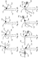
- FIGs. 2A-2N each show different steps in the assembly of the rotor blades of the wind turbine from Fig. 1 according to a first embodiment.
- a first step S1 in the assembly of rotor blades of a wind energy installation according to a first exemplary embodiment is shown.
- a hub 110 of the wind energy installation 100 has a mounting arm 200 on its first rotor blade connection 111.
- the mounting arm 200 can be mounted on the first rotor blade connection 111 of the rotor hub 110 while the hub 110 is on the ground.
- the mounting arm 200 can also be mounted when the hub 110 is already mounted.
- the hub 110 can optionally be pulled up from the ground by means of the mounting arm 200 and mounted. This can take place, for example, by means of a crane rope 300.
- the mounting arm 200 has at least a first and second section 210, 220 and a joint 230 between the first and second section 210, 220.
- the mounting arm 200 is attached to the first rotor blade connection 111, which is optionally located in the 3 o'clock or 9 o'clock position (or 90 ° or 270 °).
- the rotor hub 110 is rotated, for example, by +/- 30 degrees with the aid of the mounting arm 200, so that a second rotor blade connection 112 is essentially in the 9 o'clock or 3 o'clock position (or 270 ° or 90 °) .
- the rotation of the rotor hub 110 can take place with the aid of the mounting arm 200 and in particular the weight of the mounting arm 200.
- the mounting arm 200 or the first and second sections 210, 220 are aligned essentially straight.
- the swivel joint 230 is thus in a first position.
- step S3 Figure 2C
- the hinge 230 and the second section 220 are rotated so that the hinge 230 is in a second position.
- the second section 220 is arranged essentially horizontally.
- the adjustment of the second section 220 takes place optionally with the aid of the sick rope 300.
- step S4 ( Figure 2D ) the hub 110 is rotated further by lowering the assembly arm 200 so that the second rotor blade connection 112 is essentially in the 3 o'clock position.
- step S5 a first rotor blade 108 is fastened to the second rotor blade connection 112 by means of a rotor blade cross member 400 and the crane cable 300.
- the first rotor blade 108 is pulled upwards essentially horizontally by means of the cross member 400 and is fastened to the second rotor blade connection 112.
- step S6 the rotor blade traverse 400 is attached to the second section 220 of the mounting arm 200.
- step S7 Figure 2G
- the second section 220 of the mounting arm 200 is pulled up by 60 degrees, specifically by means of the rotor blade cross member 400 and the crane rope 300.
- step S8 Figure 2H
- the joint 230 is released and the second section 220 is lowered by 60 degrees by means of the traverse 400 and the crane rope 300.
- step S9 the rotor hub 110 is rotated by pulling up the mounting arm 200.
- the first rotor blade connection 111 is rotated from the 3 o'clock position to a 1 o'clock position, so that the second rotor blade connection 112 is in a 4 o'clock position and the third rotor blade connection 113 is in a 9 o'clock position is located.
- step S10 Figure 2J
- a second rotor blade 108 is mounted on the third rotor blade connection 113 by means of the rotor blade cross member 400 and the crane cable 300.
- step S11 Figure 2K
- the rotor blade traverse 400 engages in or on the second section 220.
- step S12 ( Figure 2L ) the hub 110 is rotated by means of the mounting arm 200 so that the first rotor blade connection 111 is in the 3 o'clock position.
- step S12 ( Figure 2M ) the joint 230 is released and the second section 220 of the mounting arm 200 is pulled upwards by 30 degrees, so that the first and second sections 210, 220 are straight.
- step S14 the mounting arm 200 is dismantled and a third rotor blade 108 is mounted on the first rotor blade connection 111 by means of the rotor blade cross member 400 and the crane cable 300, so that all three rotor blades 108 are mounted.
- Figs. 3A-3L each show a schematic representation of a wind energy installation during assembly of the rotor blades of the wind energy installation according to a second exemplary embodiment.
- a mounting arm 200 is mounted on a first rotor blade connection 111 of the hub 110 by means of a crane rope 300.
- the mounting arm 200 according to the second exemplary embodiment can correspond to the mounting arm 200 according to the first exemplary embodiment.
- the mounting arm 200 has at least a first and second section 210, 220 and a joint 230 between the first and second section 210, 220.
- the first section 210 has a first and a second end 211, 212, the first end 211 being mountable on a rotor blade connection, here the first rotor blade connection 111.
- the second end 212 of the first section 210 is coupled to or attached to the hinge 230.
- the second section 220 has a first end 221 that is attached to the hinge 230.
- the hinge 230 is lockable and can allow multiple positions so that the angle between the first and second sections 210, 220 can be adjusted.
- the joint 230 has a drive 231, by means of which an angle between the first and second sections 210, 220 can be set.
- the joint 230 can optionally be configured to rotate the second section 220 along its longitudinal axis.
- step S102 ( Figure 3B ) the angle between the first and second sections 210, 220 is set in such a way that the second section 220 of the mounting arm 200 is essentially horizontal.
- the second rotor blade connection 112 is in the 9 o'clock position.
- step S103 Figure 3C
- a first rotor blade 108 can be mounted on the second rotor blade connection 112 by means of the rotor blade cross member 400 and the crane cable 300.
- step S104 ( Figure 3D ) the rotor blade traverse 400 is detached from the mounted first rotor blade 108 and attached to the second section 220 of the mounting arm 200.
- step S105 ( Figure 3E ) the mounting arm is straightened and the rotor hub 110 is rotated 30 degrees.
- step S106 Figure 3F the rotor blade traverse 400 is released and the mounting arm can be rotated 180 degrees using the pitch drive.
- step S107 the angle between the first and second sections 210, 220 of the mounting arm 200 is rotated so that the first rotor blade connection 111 is in a 1 o'clock position and the second section 220 is designed essentially horizontally.
- step S108 Figure 3H
- a second rotor blade 108 is mounted in a 9 o'clock position by means of the rotor blade traverse 400 and the crane cable 300.
- step S109 Figure 3I
- the rotor blade traverse 400 is removed from the mounted second rotor blade 108 and attached to the second section 220 of the mounting arm 200.
- step S110 ( Figure 3J ) the rotor hub 110 is rotated by straightening the mounting arm 200 and the rotor blade traverse 400 with the attached second section 220 of the mounting arm 200 is lowered by 60 °.
- step S111 ( Figure 3K ) the assembly arm 200 is dismantled by means of the rotor blade traverse 400 and the crane cable 300 and a third rotor blade 108 can be mounted in step S112 on the first rotor blade connection 111 by means of the rotor blade traverse 400 and the crane cable 300.
- the mounting arm according to the invention is designed in several stages and can consist of a steel structure.
- a first end of the first section of the mounting arm can be screwed to a rotor blade flange bearing of the hub.
- the mounting arm preferably has attachment points which serve to mount the hub on the wind energy installation. This means that the rotor hub can be mounted using the mounting arm.
- a receiving link can be provided in order to be connected to a rotor blade traverse.
- the multi-level assembly arm can be accessed from the inside in order to be able to control the connection with the rotor blade traverse.
- the mounting arm and optionally the rotor blade traverse can have a weight by means of which the rotor hub can be rotated with the aid of gravity.
- the joint in the mounting arm serves to reduce the lever arm and a reduction in crane loads and the required lifting height.
- the joint can be locked in at least three positions.
- the rotor blade traverse according to the invention can have a tilt function of, for example, +/- 30 degrees.
- the tilting function of the traverse makes it possible to improve assembly of the rotor blades, which are in the Figures 2F, 2G, 2H , 2I, 2K and 2L is made possible.
- no rotor blade cross member with a tilting function is required, since this can be compensated for by the drivable joint.
Abstract
Die Erfindung betrifft ein Verfahren zur Montage von Rotorblättern (108) an einer Rotornabe (110) mit drei Rotorblattanschlüssen (111-113) unter Zuhilfenahme eines Montagearms (200), der einen ersten Abschnitt (210) und einen zweiten Abschnitt (220) aufweist, welche über ein Gelenk (230) miteinander gekoppelt sind, so dass der Winkel zwischen dem ersten und zweiten Abschnitt (210, 220) variierbar ist. Die Erfindung betrifft zudem einen Montagearm (200) zur Montage von Rotorblättern einer Windenergieanlage. Der Montagearm (200) weist einen ersten Abschnitt (210) und einen zweiten Abschnitt (220) auf, welche durch ein Drehgelenk (230) miteinander drehbar verbunden sind, wobei der erste Abschnitt ein erstes und zweites Ende aufweist, wobei das erste Ende an einem Rotorblattanschluss einer Rotornabe einer Windenergieanlage befestigbar ist, wobei das zweite Ende des ersten Abschnitts an dem Drehgelenk befestigbar ist, wobei das Gelenk in mindestens drei Positionen arretierbar ist.

Description
Die vorliegende Erfindung betrifft ein Verfahren zur Montage von Rotorblättern einer Windenergieanlage und einen Montagearm.The present invention relates to a method for assembling rotor blades of a wind turbine and to an assembly arm.
Bei der Errichtung einer Windenergieanlage gestaltet sich die Montage der Rotorblätter an einer Rotornabe der Windenergieanlage als schwierig, insbesondere, wenn ungünstige Wetterbedingungen (wie beispielsweise Wind, Regen etc.) vorliegen. Dahergibt es Bestrebungen, die Montage von Rotorblättern einer Windenergieanlage zu verbessern.When setting up a wind energy installation, the assembly of the rotor blades on a rotor hub of the wind energy installation turns out to be difficult, in particular when unfavorable weather conditions (such as wind, rain, etc.) are present. There are therefore efforts to improve the assembly of rotor blades of a wind turbine.
Insbesondere bei großen Windenergieanlagen mit einer hohen Nabenhöhe und langen Rotorblättern kann es vorkommen, dass die zur Verfügung stehenden Kräne nicht ausreichen, um die Rotorblätter wie bislang zu befestigen.In particular in the case of large wind energy installations with a high hub height and long rotor blades, it can happen that the available cranes are not sufficient to fasten the rotor blades as before.
In der prioritätsbegründenden deutschen Patentanmeldung hat das Deutsche Patent- und Markenamt die folgenden Dokumente recherchiert:
Es ist daher eine Aufgabe der vorliegenden Erfindung, eine effektive Montage von Rotorblättern an einer Rotornabe der Windenergieanlage vorzusehen. Es ist insbesondere eine Aufgabe der vorliegenden Erfindung, eine Montage von Rotorblättern an einer Rotornabe der Windenergieanlage vorzusehen, wobei weniger Arbeitsschritte benötigt werden.It is therefore an object of the present invention to provide an effective assembly of rotor blades on a rotor hub of the wind energy installation. In particular, it is an object of the present invention to provide an assembly of rotor blades on a rotor hub of the wind energy installation, with fewer work steps being required.
Diese Aufgabe wird durch ein Verfahren zur Montage von Rotorblättern einer Windenergieanlage gemäß Anspruch 1 sowie durch einen Montagearm gemäß Anspruch 8 gelöst.This object is achieved by a method for assembling rotor blades of a wind energy installation according to claim 1 and by a mounting arm according to claim 8.
Gemäß der Erfindung wird vorgeschlagen, bei der Montage der Rotorblätter der Windenergieanlage einen Montagearm zu verwenden, der mehrstufig ausgestaltet ist und es erlaubt, dass mindestens zwei Abschnitte des Montagearms zueinander gedreht oder verschwenkt werden können. Der erfindungsgemäße Montagearm kann einen ersten und zweiten Abschnitt sowie ein Gelenk zwischen dem ersten und zweiten Abschnitt aufweisen, so dass der erste und zweite Abschnitt zueinander verschwenkbar angeordnet sind. Zur Montage der Rotorblätter kann der Montagearm an einem ersten Rotorblattanschluss der Rotornabe befestigt werden. Dies kann erfolgen, wenn der Rotorblattanschluss sich in einer 3-Uhr-Position (90°) oder 9-Uhr-Position (270°) befindet. Der Montagearm ist hierbei vorzugsweise gerade ausgestaltet. Anschließend kann die Rotornabe unter Zuhilfenahme des Montagearms beispielsweise um 30 Grad gedreht werden, so dass ein zweiter Rotorblattanschluss sich in der 9-Uhr- oder 3-Uhr-Position (270°, 90°) befindet, was eine im Wesentlichen waagerechte Montage des ersten Rotorblatts ermöglicht. Nach der Drehung der Rotornabe unter Zuhilfenahme des Montagearms kann der Winkel zwischen dem ersten und zweiten Abschnitt des Montagearms verstellt werden, so dass damit auch der Schwerpunkt des Montagearms verändert wird. Das erste Rotorblatt kann beispielsweise mittels einer Rotorblatttraverse an dem zweiten Rotorblattanschluss befestigt werden, welcher sich in der 3-Uhr- oder 9-Uhr-Position (90°, 270°) befindet. Anschließend kann der Montagearm beispielsweise unter Zuhilfenahme der Rotorblatttraverse angehoben werden, so dass sich die Rotornabe so dreht, dass ein dritter Rotorblattanschluss sich in der 9-Uhr- oder 3-Uhr-Position (270°, 90°) befindet und ein zweites Rotorblatt wiederum mittels der Rotorblatttraverse an dem dritten Rotorblattanschluss montiert werden kann, wobei das zweite Rotorblatt mittels der Rotorblatttraverse im Wesentlichen waagerecht nach oben gezogen werden kann.According to the invention, it is proposed to use a mounting arm when assembling the rotor blades of the wind energy installation, which is designed in several stages and allows at least two sections of the mounting arm to be rotated or pivoted relative to one another. The mounting arm according to the invention can have a first and second section and a joint between the first and second section, so that the first and second sections are arranged such that they can pivot with respect to one another. To assemble the rotor blades, the assembly arm can be attached to a first rotor blade connection of the rotor hub. This can be done when the rotor blade connection is in a 3 o'clock position (90 °) or 9 o'clock position (270 °). The mounting arm is preferably designed straight. The rotor hub can then be rotated, for example, by 30 degrees with the aid of the mounting arm, so that a second rotor blade connection is in the 9 o'clock or 3 o'clock position (270 °, 90 °), which means that the first is essentially horizontal Rotor blade allows. After rotating the rotor hub with the help of the mounting arm, the angle between the first and second section of the mounting arm can be adjusted so that the center of gravity of the mounting arm is also changed. The first rotor blade can be fastened to the second rotor blade connection, which is in the 3 o'clock or 9 o'clock position (90 °, 270 °), for example by means of a rotor blade cross member. The assembly arm can then be raised, for example with the help of the rotor blade traverse, so that the rotor hub rotates so that a third rotor blade connection is in the 9 o'clock or 3 o'clock position (270 °, 90 °) and a second rotor blade is in turn can be mounted on the third rotor blade connection by means of the rotor blade traverse, wherein the second rotor blade can be pulled upwards essentially horizontally by means of the rotor blade traverse.
Anschließend kann die Rotornabe weitergedreht werden, bis der erste Rotorblattanschluss sich in der 3-Uhr- oder 9-Uhr-Position (90°, 270°) befindet. Dies erfolgt beispielsweise unter Zuhilfenahme des Montagearms sowie der Rotorblatttraverse, welche an dem Montagearm befestigt ist. Anschließend kann der Montagearm entfernt und das dritte Rotorblatt an dem ersten Rotorblattanschluss montiert werden.The rotor hub can then be turned further until the first rotor blade connection is in the 3 o'clock or 9 o'clock position (90 °, 270 °). This is done, for example, with the aid of the mounting arm and the rotor blade crossbeam which is attached to the mounting arm. The mounting arm can then be removed and the third rotor blade can be mounted on the first rotor blade connection.
Die Erfindung betrifft ebenfalls einen Montagearm, welcher bei der Errichtung einer Windenergieanlage und insbesondere bei der Montage der Rotorblätter verwendet wird. Der Montagearm weist mindestens einen ersten und zweiten Abschnitt auf, welche durch ein Drehlager miteinander verbunden sind, so dass der erste und zweite Abschnitt gegeneinander drehbar bzw. verschwenkbar ausgestaltet sind. Ein erstes Ende des ersten Abschnittes des Montagearms ist zum Koppeln an einem Rotorblattanschluss einer Rotornabe ausgestaltet und weist beispielsweise eine erste Befestigungseinheit auf. Das zweite Ende des ersten Abschnitts des Montagearms ist mit dem Gelenk gekoppelt.The invention also relates to an assembly arm which is used in the erection of a wind turbine and in particular in the assembly of the rotor blades. The mounting arm has at least one first and second section, which are connected to one another by a pivot bearing, so that the first and second sections are designed to be rotatable or pivotable with respect to one another. A first end of the first section of the mounting arm is designed for coupling to a rotor blade connection of a rotor hub and has, for example, a first fastening unit. The second end of the first section of the mounting arm is coupled to the hinge.
Gemäß einem Aspekt der vorliegenden Erfindung ist die Länge des zweiten Abschnitts größer als die Länge des ersten Abschnitts.According to one aspect of the present invention, the length of the second section is greater than the length of the first section.
Gemäß einem weiteren Aspekt der vorliegenden Erfindung erlaubt das Gelenk bzw. das Drehlager mindestens zwei Positionen.According to a further aspect of the present invention, the joint or the pivot bearing allows at least two positions.
Gemäß einem weiteren Aspekt der vorliegenden Erfindung weist der zweite Abschnitt des Montagearms Aufnahmekulissen zur Aufnahme der Rotorblatttraverse auf.According to a further aspect of the present invention, the second section of the mounting arm has receiving links for receiving the rotor blade traverse.
Gemäß einem weiteren Aspekt der vorliegenden Erfindung ist der erste und/oder zweite Abschnitt des Montagearms von innen begehbar.According to a further aspect of the present invention, the first and / or second section of the mounting arm is accessible from the inside.
Gemäß einem weiteren Aspekt der vorliegenden Erfindung ist das Gelenk des Montagearms hydraulisch oder elektrisch verstellbar.According to a further aspect of the present invention, the joint of the mounting arm can be adjusted hydraulically or electrically.
Die vorliegende Erfindung ist insbesondere relevant bei der Montage einer getriebelosen Windenergieanlage.The present invention is particularly relevant when assembling a gearless wind energy installation.
Mithilfe des Montagearms kann die Rotornabe montiert werden. Hierzu muss der Montagearm an einen Rotorblattanschluss montiert sein und der Montagearm zusammen mit der Nabe kann dann mittels eines Kranseiles nach oben gezogen werden, so dass die Nabe an der Gondel der Windenergieanlage montiert werden kann. Durch die mehrstufige Ausgestaltung des Montagearmes und durch das Gelenk des Montagearmes, welches mehrere Positionen verfügen kann, kann eine Montage der Rotorblätter der Windenergieanlage mit weniger Hüben des Krans erfolgen. Mit dem erfindungsgemäßen Montagearm können alle drei Rotorblätter im Wesentlichen in einer horizontalen Lage montiert werden.The rotor hub can be mounted using the mounting arm. For this purpose, the mounting arm must be mounted on a rotor blade connection and the mounting arm together with the hub can then be pulled up by means of a crane rope so that the hub can be mounted on the nacelle of the wind turbine. Due to the multi-stage configuration of the assembly arm and the joint of the assembly arm, which can have several positions, the rotor blades of the wind energy installation can be assembled with fewer crane lifts. With the mounting arm according to the invention, all three rotor blades can be mounted essentially in a horizontal position.
Ferner ist kein Axialsicherungsseil bei der Montage der Rotorblätter erforderlich. Bei der Montage der Rotorblätter kann der erfindungsgemäße Montagearm dazu verwendet werden, die Nabe aufgrund seines Eigengewichts sowie der Drehmomente zu drehen.Furthermore, no axial safety rope is required when assembling the rotor blades. When assembling the rotor blades, the assembly arm according to the invention can be used to rotate the hub due to its own weight and the torques.
Weitere Ausgestaltungen der Erfindung sind Gegenstand der Unteransprüche.
- Fig. 1
- zeigt eine schematische Darstellung einer Windenergieanlage gemäß der Erfindung,
- Figs. 2A - 2N
- zeigen jeweils verschiedene Schritte bei der Montage der Rotorblätter der Windenergieanlage von
Fig. 1 gemäß einem ersten Ausführungsbeispiel, und - Figs. 3A - 3L
- zeigen jeweils eine schematische Darstellung einer Windenergieanlage bei einer Montage von Rotorblättern gemäß einem zweiten Ausführungsbeispiel.
- Fig. 1
- shows a schematic representation of a wind turbine according to the invention,
- Figs. 2A-2N
- each show different steps in the assembly of the rotor blades of the wind turbine from
Fig. 1 according to a first embodiment, and - Figs. 3A - 3L
- each show a schematic representation of a wind energy installation during the assembly of rotor blades according to a second exemplary embodiment.
Gemäß der Erfindung können Positionen des aerodynamischen Rotors 106 anhand eines Uhr-Zifferblattes oder anhand von Winkelangaben beschrieben werden. 0° entspricht dabei einer 12-Uhr-Position. 90° entspricht einer 3-Uhr-Position, 180° entspricht einer 6-Uhr-Position und 270° entspricht einer 9-Uhr-Position.According to the invention, positions of the
Die Windenergieanlage weist einen elektrischen Generator 105 auf. Ein Rotor des Generators 105 ist mit dem aerodynamischen Rotor 106 direkt oder indirekt gekoppelt, so dass bei einer Drehung des aerodynamischen Rotors 106 auch der Rotor des Generators 105 rotiert und der Generator 105 dadurch eine elektrische Energie erzeugt.The wind energy installation has an
Daher kann die Nabe 110 optional mittels des Montagearms 200 vom Boden nach oben gezogen und montiert werden. Dies kann beispielsweise mittels eines Kranseiles 300 erfolgen.Therefore, the
Der Montagearm 200 weist mindestens einen ersten und zweiten Abschnitt 210, 220 sowie ein Gelenk 230 zwischen dem ersten und zweiten Abschnitt 210, 220 auf. Der Montagearm 200 ist an dem ersten Rotorblattanschluss 111 befestigt, welcher sich optional in der 3-Uhr- oder 9-Uhr-Position (bzw. 90° oder 270°) befindet. In Schritt S2 (
Das Drehen der Rotornabe 110 kann unter Zuhilfenahme des Montagearms 200 und insbesondere des Gewichts des Montagearms 200 erfolgen. Während des ersten und zweiten Schrittes S1, S2 ist der Montagearm 200 bzw. der erste und zweite Abschnitt 210, 220 im Wesentlichen gerade ausgerichtet. Das Drehgelenk 230 befindet sich somit in einer ersten Position. In Schritt S3 (
In Schritt S4 (
In Schritt S5 (
In Schritt S9 (
In Schritt S14 (
In Schritt S107 (
Damit sind alle drei Rotorblätter 108 montiert.All three
Der erfindungsgemäße Montagearm ist mehrstufig ausgestaltet und kann aus einer Stahlkonstruktion bestehen. Ein erstes Ende des ersten Abschnitts des Montagearms kann an einem Rotorblattflanschlager der Nabe angeschraubt werden. Vorzugsweise weist der Montagearm im Gesamtschwerpunkt mit angeschraubter Rotornabe Anschlagpunkte, welche dazu dienen, die Nabe an der Windenergieanlage zu montieren, auf. Damit kann die Rotornabe mittels des Montagearms montiert werden. Im Bereich des zweiten Abschnitts des Montagearms kann eine Aufnahmekulisse vorgesehen sein, um mit einer Rotorblatttraverse verbunden zu werden. Optional kann der mehrstufige Montagearm von innen begehbar sein, um das Verbinden mit der Rotorblatttraverse steuern zu können. Der Montagearm sowie optional die Rotorblatttraverse kann ein Gewicht aufweisen, mittels welchem die Rotornabe unter Zuhilfenahme der Schwerkraft gedreht werden kann.The mounting arm according to the invention is designed in several stages and can consist of a steel structure. A first end of the first section of the mounting arm can be screwed to a rotor blade flange bearing of the hub. In the overall center of gravity with the screwed-on rotor hub, the mounting arm preferably has attachment points which serve to mount the hub on the wind energy installation. This means that the rotor hub can be mounted using the mounting arm. In the area of the second section of the mounting arm, a receiving link can be provided in order to be connected to a rotor blade traverse. Optionally, the multi-level assembly arm can be accessed from the inside in order to be able to control the connection with the rotor blade traverse. The mounting arm and optionally the rotor blade traverse can have a weight by means of which the rotor hub can be rotated with the aid of gravity.
Das Gelenk in dem Montagearm dient dazu, den Hebelarm und eine Verminderung der Kranlasten sowie der erforderlichen Hubhöhe zu verringern. Das Gelenk kann in mindestens drei Positionen arretiert werden.The joint in the mounting arm serves to reduce the lever arm and a reduction in crane loads and the required lifting height. The joint can be locked in at least three positions.
Die Rotorblatttraverse gemäß der Erfindung kann eine Neigefunktion um beispielsweise +/- 30 Grad aufweisen. Durch die Neigefunktion der Traverse kann eine Montage der Rotorblätter verbessert werden, die in den
Claims (10)
Befestigen eines Montagearmes (200) an einem ersten Rotorblattanschluss (111), wobei der Montagearm (200) einen ersten Abschnitt (210) und einen zweiten Abschnitt (220) aufweist, welche über ein Gelenk (230) miteinander gekoppelt sind, so dass der Winkel zwischen dem ersten und zweiten Abschnitt (210, 220) variierbar ist,
Drehen der Nabe (110) bis sich der erste Rotorblattanschluss (111) in einer 90°-Position oder einer 270°-Position befindet,
Befestigen eines ersten Endes (211) des ersten Abschnitts (210) des Montagearms (200) an dem ersten Rotorblattanschluss (111) der Rotornabe (110),
Drehen der Rotornabe (110) unter Zuhilfenahme des Montagearms (200), bis der zweite Rotorblattanschluss (112) sich in einer 270°-Position oder einer 90°-Position befindet,
wobei beim Drehen der Rotornabe (110) der Winkel zwischen dem ersten und zweiten Abschnitt (210, 220) des Montagearms (200) variiert wird,
waagerechtes Anheben eines ersten Rotorblattes (108), insbesondere mittels einer Rotorblatttraverse (400) und einem Kranseil (300), so dass eine waagerechte Montage des ersten Rotorblattes (108) an dem zweiten Rotorblattanschluss (112) der Rotornabe (110) erfolgt,
Drehen der Rotornabe (110) unter Zuhilfenahme des Montagearms (200), bis der dritte Rotorblattanschluss (113) sich in einer 270°-Position oder einer 90°-Position befindet,
Montieren des zweiten Rotorblatts (108) an den dritten Rotorblattanschluss (113), insbesondere unter Zuhilfenahme einer Rotorblatttraverse (400) und des Kranseils (300),
Drehen der Rotornabe (110) unter Zuhilfenahme des Montagearms (200), bis der erste Rotorblattanschluss (111) sich in der 90°-Position oder der 270°-Position befindet,
Montieren eines dritten Rotorblatts (108), insbesondere unter Zuhilfenahme der Rotorblatttraverse (400) und des Kranseils (300), an dem ersten Rotorblattanschluss (111),
wobei der Winkel zwischen dem ersten und zweiten Abschnitt (210, 220) des Montagearms (200) durch das Drehgelenk (230) variiert wird.Method for assembling rotor blades (108) of a wind energy installation (100), wherein the wind energy installation (100) has a rotor hub (110) with three rotor blade connections (111-113), on each of which a rotor blade (108) is to be installed, with the following steps
Fastening a mounting arm (200) to a first rotor blade connection (111), the mounting arm (200) having a first section (210) and a second section (220) which are coupled to one another via a joint (230) so that the angle can be varied between the first and second sections (210, 220),
Rotating the hub (110) until the first rotor blade connection (111) is in a 90 ° position or a 270 ° position,
Fastening a first end (211) of the first section (210) of the mounting arm (200) to the first rotor blade connection (111) of the rotor hub (110),
Rotating the rotor hub (110) with the aid of the mounting arm (200) until the second rotor blade connection (112) is in a 270 ° position or a 90 ° position,
wherein when the rotor hub (110) is rotated, the angle between the first and second sections (210, 220) of the mounting arm (200) is varied,
horizontal lifting of a first rotor blade (108), in particular by means of a rotor blade traverse (400) and a crane rope (300), so that the first rotor blade (108) is mounted horizontally on the second rotor blade connection (112) of the rotor hub (110),
Rotating the rotor hub (110) with the aid of the mounting arm (200) until the third rotor blade connection (113) is in a 270 ° position or a 90 ° position,
Mounting the second rotor blade (108) on the third rotor blade connection (113), in particular with the aid of a rotor blade cross member (400) and the crane rope (300),
Rotating the rotor hub (110) with the aid of the mounting arm (200) until the first rotor blade connection (111) is in the 90 ° position or the 270 ° position,
Mounting a third rotor blade (108), in particular with the aid of the rotor blade cross member (400) and the crane rope (300), on the first rotor blade connection (111),
wherein the angle between the first and second sections (210, 220) of the mounting arm (200) is varied by the pivot joint (230).
das Drehgelenk (230) in mindestens drei Positionen drehbar und arretierbar ist.Method for assembling rotor blades (108) of a wind energy installation (100) according to claim 1, wherein
the swivel joint (230) can be rotated and locked in at least three positions.
das Drehgelenk (230) elektrisch oder hydraulisch antreibbar ist und das Drehgelenk (230) an mindestens drei Positionen arretierbar ist.Method for assembling rotor blades (108) of a wind energy installation (100) according to claim 1, wherein
the swivel joint (230) can be driven electrically or hydraulically and the swivel joint (230) can be locked in at least three positions.
der Montagearm (200) nach Befestigung an dem ersten Rotorblattanschluss (111) und vor Montage des ersten Rotorblattes (108) an den zweiten Rotorblattanschluss (112) zweimal variiert wird.Method for assembling rotor blades (108) of a wind energy installation (100) according to claim 1 or 2, wherein
the mounting arm (200) is varied twice after attachment to the first rotor blade connection (111) and before mounting the first rotor blade (108) to the second rotor blade connection (112).
der Winkel zwischen dem ersten und zweiten Abschnitt (210, 220) des Montagearms (200) einmal variiert wird.Method for assembling rotor blades (108) of a wind energy installation (100) according to one of Claims 1 to 4, wherein
the angle between the first and second sections (210, 220) of the mounting arm (200) is varied once.
der Winkel zwischen dem ersten und zweiten Abschnitt (210, 220) des Montagearms (200) nach Montage des zweiten Rotorblattes (108) an dem dritten Rotorblattanschluss (113) mindestens einmal variiert wird.Method for assembling rotor blades (108) of a wind energy installation (100) according to one of Claims 1 to 5, wherein
the angle between the first and second sections (210, 220) of the mounting arm (200) is varied at least once after mounting the second rotor blade (108) on the third rotor blade connection (113).
ein Winkel zwischen einem ersten und zweiten Abschnitt (210, 220) des Montagearms (200) während des Drehens der Rotornabe (110) unter Zuhilfenahme des Montagearms (200) und insbesondere einer Rotorblatttraverse (400) geändert wird.Method for assembling rotor blades (108) of a wind energy installation (100) according to one of Claims 1 to 3, wherein
an angle between a first and second section (210, 220) of the mounting arm (200) is changed during the rotation of the rotor hub (110) with the aid of the mounting arm (200) and in particular a rotor blade traverse (400).
einem ersten und zweiten Abschnitt (210, 220), welche durch ein Drehgelenk (230) miteinander drehbar verbunden sind,
wobei der erste Abschnitt (210) ein erstes und zweites Ende (211, 212) aufweist, wobei das erste Ende (211) an einem Rotorblattanschluss (111-113) einer Rotornabe (110) einer Windenergieanlage (100) befestigbar ist,
wobei ein zweites Ende (212) des ersten Abschnitts (210) an dem Drehgelenk (230) befestigbar ist,
wobei das Gelenk (230) in mindestens drei Positionen arretierbar ist.Mounting arm (200) for mounting rotor blades (108) of a wind energy installation (100), with
a first and second section (210, 220) which are rotatably connected to one another by a swivel joint (230),
wherein the first section (210) has a first and a second end (211, 212), the first end (211) being attachable to a rotor blade connection (111-113) of a rotor hub (110) of a wind turbine (100),
wherein a second end (212) of the first section (210) can be fastened to the swivel joint (230),
wherein the joint (230) can be locked in at least three positions.
Applications Claiming Priority (1)
| Application Number | Priority Date | Filing Date | Title |
|---|---|---|---|
| DE102019126984 | 2019-10-08 |
Publications (3)
| Publication Number | Publication Date |
|---|---|
| EP3805553A1 true EP3805553A1 (en) | 2021-04-14 |
| EP3805553C0 EP3805553C0 (en) | 2023-06-07 |
| EP3805553B1 EP3805553B1 (en) | 2023-06-07 |
Family
ID=72744653
Family Applications (1)
| Application Number | Title | Priority Date | Filing Date |
|---|---|---|---|
| EP20199857.2A Active EP3805553B1 (en) | 2019-10-08 | 2020-10-02 | Method and device for installing rotor blades of a wind turbine |
Country Status (3)
| Country | Link |
|---|---|
| US (1) | US11692529B2 (en) |
| EP (1) | EP3805553B1 (en) |
| CN (1) | CN112628084A (en) |
Cited By (2)
| Publication number | Priority date | Publication date | Assignee | Title |
|---|---|---|---|---|
| EP4276301A1 (en) * | 2022-05-13 | 2023-11-15 | Wobben Properties GmbH | Method for mounting rotor blades on a wind turbine and mounting adapter for mounting rotor blades on a wind turbine |
| EP4303431A1 (en) * | 2022-07-04 | 2024-01-10 | Wobben Properties GmbH | Method for mounting rotor blades on a wind turbine and mounting adapter for mounting rotor blades on a wind turbine |
Families Citing this family (1)
| Publication number | Priority date | Publication date | Assignee | Title |
|---|---|---|---|---|
| DE102019106969A1 (en) * | 2019-03-19 | 2020-09-24 | Wobben Properties Gmbh | Method for assembling rotor blades of a wind turbine |
Citations (7)
| Publication number | Priority date | Publication date | Assignee | Title |
|---|---|---|---|---|
| DE20109835U1 (en) | 2001-06-15 | 2002-01-24 | Gerken Gmbh | platform |
| WO2003012291A1 (en) | 2001-07-20 | 2003-02-13 | Aloys Wobben | Method for in situ construction of a wind power plant |
| DE102008033857A1 (en) | 2008-07-19 | 2010-01-21 | GEO Gesellschaft für Energie und Ökologie mbH | Rotor blade mounting device for wind turbine, has pivoting mechanism fixed in area of pivoting point of frame and pivotable at ninety degrees around frame, where pivoting mechanism has structure for retaining crane hook |
| EP1597477B1 (en) | 2003-02-10 | 2010-04-14 | Aloys Wobben | Method for mounting rotor blades |
| US20110185571A1 (en) | 2010-01-14 | 2011-08-04 | Karl Aage Maj | Clamp for clamping a blade for a wind turbine and method of installing wind turbine blades |
| WO2014076825A1 (en) * | 2012-11-16 | 2014-05-22 | 三菱重工業株式会社 | Wind power generator assembly method and counterweight used therein |
| DE102015008610B3 (en) | 2015-07-06 | 2016-12-15 | Axzion Gks Stahl Und Maschinenbau Gmbh | Transport device for elongated goods |
Family Cites Families (5)
| Publication number | Priority date | Publication date | Assignee | Title |
|---|---|---|---|---|
| DK2650537T3 (en) * | 2012-04-11 | 2015-02-02 | Siemens Ag | Counterweight device for equalizing and adjusting a partially mounted rotor of a wind turbine and a method thereof |
| US9938958B2 (en) * | 2012-07-19 | 2018-04-10 | Humberto Antonio RUBIO | Vertical axis wind and hydraulic turbine with flow control |
| EP3001029B1 (en) * | 2014-09-26 | 2018-12-12 | GE Renewable Technologies Wind B.V. | Counterweight systems for a wind turbine and methods |
| DE102016200160A1 (en) * | 2016-01-08 | 2017-07-13 | Wobben Properties Gmbh | Lifting device for lifting a component of a wind turbine and method for mounting components of a wind turbine |
| US10823138B2 (en) * | 2018-08-31 | 2020-11-03 | General Electric Company | Counterweight assembly for use during single blade installation of a wind turbine |
-
2020
- 2020-10-02 EP EP20199857.2A patent/EP3805553B1/en active Active
- 2020-10-05 US US17/063,164 patent/US11692529B2/en active Active
- 2020-10-09 CN CN202011072812.9A patent/CN112628084A/en active Pending
Patent Citations (7)
| Publication number | Priority date | Publication date | Assignee | Title |
|---|---|---|---|---|
| DE20109835U1 (en) | 2001-06-15 | 2002-01-24 | Gerken Gmbh | platform |
| WO2003012291A1 (en) | 2001-07-20 | 2003-02-13 | Aloys Wobben | Method for in situ construction of a wind power plant |
| EP1597477B1 (en) | 2003-02-10 | 2010-04-14 | Aloys Wobben | Method for mounting rotor blades |
| DE102008033857A1 (en) | 2008-07-19 | 2010-01-21 | GEO Gesellschaft für Energie und Ökologie mbH | Rotor blade mounting device for wind turbine, has pivoting mechanism fixed in area of pivoting point of frame and pivotable at ninety degrees around frame, where pivoting mechanism has structure for retaining crane hook |
| US20110185571A1 (en) | 2010-01-14 | 2011-08-04 | Karl Aage Maj | Clamp for clamping a blade for a wind turbine and method of installing wind turbine blades |
| WO2014076825A1 (en) * | 2012-11-16 | 2014-05-22 | 三菱重工業株式会社 | Wind power generator assembly method and counterweight used therein |
| DE102015008610B3 (en) | 2015-07-06 | 2016-12-15 | Axzion Gks Stahl Und Maschinenbau Gmbh | Transport device for elongated goods |
Cited By (2)
| Publication number | Priority date | Publication date | Assignee | Title |
|---|---|---|---|---|
| EP4276301A1 (en) * | 2022-05-13 | 2023-11-15 | Wobben Properties GmbH | Method for mounting rotor blades on a wind turbine and mounting adapter for mounting rotor blades on a wind turbine |
| EP4303431A1 (en) * | 2022-07-04 | 2024-01-10 | Wobben Properties GmbH | Method for mounting rotor blades on a wind turbine and mounting adapter for mounting rotor blades on a wind turbine |
Also Published As
| Publication number | Publication date |
|---|---|
| EP3805553C0 (en) | 2023-06-07 |
| US20210102526A1 (en) | 2021-04-08 |
| CN112628084A (en) | 2021-04-09 |
| EP3805553B1 (en) | 2023-06-07 |
| US11692529B2 (en) | 2023-07-04 |
Similar Documents
| Publication | Publication Date | Title |
|---|---|---|
| EP3805553B1 (en) | Method and device for installing rotor blades of a wind turbine | |
| EP2072812B1 (en) | Method and attachment for handling a rotor hub of a wind turbine | |
| EP1597477B1 (en) | Method for mounting rotor blades | |
| EP2702266B1 (en) | Wind turbine | |
| EP2807107B1 (en) | Method and apparatus for installing a rotor hub of a wind power plant | |
| EP3211217B1 (en) | Method and device for mounting a rotor of a wind energy system | |
| DE10303555B4 (en) | Method for craneless mounting of a rotor blade of a wind energy plant | |
| EP2707322B1 (en) | Rotating tower crane | |
| WO2003069156A1 (en) | Wind energy turbine | |
| EP2226496B1 (en) | Handling device for rotor blade bearing | |
| EP3396154B1 (en) | Blade adapter for wind turbines | |
| DE102016222211A1 (en) | lift assembly | |
| EP3942175B1 (en) | Method for installing rotor blades of a wind turbine | |
| EP3825550B1 (en) | Tower segment and method of manufacturing same | |
| DE202014101685U1 (en) | Device for vibration damping of photovoltaic installations and photovoltaic installation with damping element | |
| EP3242013A1 (en) | Wind power plant with an apparatus for rotating a nacelle of the wind power plant and method for mounting a device for rotating a nacelle | |
| EP3969740B1 (en) | Wind turbine and wind turbine rotor blade | |
| EP4276301A1 (en) | Method for mounting rotor blades on a wind turbine and mounting adapter for mounting rotor blades on a wind turbine | |
| EP4303431A1 (en) | Method for mounting rotor blades on a wind turbine and mounting adapter for mounting rotor blades on a wind turbine | |
| EP3438450B1 (en) | Platform to carry out maintenance operations on a wind turbine, method of assembling such a platform and wind turbine | |
| EP4230565A1 (en) | Release device for a lift-tilt apparatus for releasing the lift-tilt apparatus from a generator segment, lift-tilt apparatus for lifting and tilting a generator segment, method of lifting and tilting a generator segment, and method for mounting a lift-tilt apparatus on a disassembled generator segment | |
| EP3284947A1 (en) | Wind turbine and method for the assembly of the wind power plant |
Legal Events
| Date | Code | Title | Description |
|---|---|---|---|
| PUAI | Public reference made under article 153(3) epc to a published international application that has entered the european phase |
Free format text: ORIGINAL CODE: 0009012 |
|
| STAA | Information on the status of an ep patent application or granted ep patent |
Free format text: STATUS: THE APPLICATION HAS BEEN PUBLISHED |
|
| AK | Designated contracting states |
Kind code of ref document: A1 Designated state(s): AL AT BE BG CH CY CZ DE DK EE ES FI FR GB GR HR HU IE IS IT LI LT LU LV MC MK MT NL NO PL PT RO RS SE SI SK SM TR |
|
| AX | Request for extension of the european patent |
Extension state: BA ME |
|
| STAA | Information on the status of an ep patent application or granted ep patent |
Free format text: STATUS: REQUEST FOR EXAMINATION WAS MADE |
|
| 17P | Request for examination filed |
Effective date: 20211014 |
|
| RBV | Designated contracting states (corrected) |
Designated state(s): AL AT BE BG CH CY CZ DE DK EE ES FI FR GB GR HR HU IE IS IT LI LT LU LV MC MK MT NL NO PL PT RO RS SE SI SK SM TR |
|
| GRAP | Despatch of communication of intention to grant a patent |
Free format text: ORIGINAL CODE: EPIDOSNIGR1 |
|
| STAA | Information on the status of an ep patent application or granted ep patent |
Free format text: STATUS: GRANT OF PATENT IS INTENDED |
|
| RIC1 | Information provided on ipc code assigned before grant |
Ipc: F03D 13/10 20160101ALI20221014BHEP Ipc: F03D 1/06 20060101AFI20221014BHEP |
|
| INTG | Intention to grant announced |
Effective date: 20221114 |
|
| GRAS | Grant fee paid |
Free format text: ORIGINAL CODE: EPIDOSNIGR3 |
|
| GRAA | (expected) grant |
Free format text: ORIGINAL CODE: 0009210 |
|
| STAA | Information on the status of an ep patent application or granted ep patent |
Free format text: STATUS: THE PATENT HAS BEEN GRANTED |
|
| AK | Designated contracting states |
Kind code of ref document: B1 Designated state(s): AL AT BE BG CH CY CZ DE DK EE ES FI FR GB GR HR HU IE IS IT LI LT LU LV MC MK MT NL NO PL PT RO RS SE SI SK SM TR |
|
| REG | Reference to a national code |
Ref country code: GB Ref legal event code: FG4D Free format text: NOT ENGLISH |
|
| REG | Reference to a national code |
Ref country code: CH Ref legal event code: EP Ref country code: AT Ref legal event code: REF Ref document number: 1575779 Country of ref document: AT Kind code of ref document: T Effective date: 20230615 Ref country code: DE Ref legal event code: R096 Ref document number: 502020003546 Country of ref document: DE |
|
| U01 | Request for unitary effect filed |
Effective date: 20230629 |
|
| U07 | Unitary effect registered |
Designated state(s): AT BE BG DE DK EE FI FR IT LT LU LV MT NL PT SE SI Effective date: 20230707 |
|
| REG | Reference to a national code |
Ref country code: LT Ref legal event code: MG9D |
|
| PG25 | Lapsed in a contracting state [announced via postgrant information from national office to epo] |
Ref country code: NO Free format text: LAPSE BECAUSE OF FAILURE TO SUBMIT A TRANSLATION OF THE DESCRIPTION OR TO PAY THE FEE WITHIN THE PRESCRIBED TIME-LIMIT Effective date: 20230907 Ref country code: ES Free format text: LAPSE BECAUSE OF FAILURE TO SUBMIT A TRANSLATION OF THE DESCRIPTION OR TO PAY THE FEE WITHIN THE PRESCRIBED TIME-LIMIT Effective date: 20230607 |
|
| U20 | Renewal fee paid [unitary effect] |
Year of fee payment: 4 Effective date: 20230928 |
|
| PG25 | Lapsed in a contracting state [announced via postgrant information from national office to epo] |
Ref country code: RS Free format text: LAPSE BECAUSE OF FAILURE TO SUBMIT A TRANSLATION OF THE DESCRIPTION OR TO PAY THE FEE WITHIN THE PRESCRIBED TIME-LIMIT Effective date: 20230607 Ref country code: HR Free format text: LAPSE BECAUSE OF FAILURE TO SUBMIT A TRANSLATION OF THE DESCRIPTION OR TO PAY THE FEE WITHIN THE PRESCRIBED TIME-LIMIT Effective date: 20230607 Ref country code: GR Free format text: LAPSE BECAUSE OF FAILURE TO SUBMIT A TRANSLATION OF THE DESCRIPTION OR TO PAY THE FEE WITHIN THE PRESCRIBED TIME-LIMIT Effective date: 20230908 |
|
| PG25 | Lapsed in a contracting state [announced via postgrant information from national office to epo] |
Ref country code: SK Free format text: LAPSE BECAUSE OF FAILURE TO SUBMIT A TRANSLATION OF THE DESCRIPTION OR TO PAY THE FEE WITHIN THE PRESCRIBED TIME-LIMIT Effective date: 20230607 |
|
| PG25 | Lapsed in a contracting state [announced via postgrant information from national office to epo] |
Ref country code: IS Free format text: LAPSE BECAUSE OF FAILURE TO SUBMIT A TRANSLATION OF THE DESCRIPTION OR TO PAY THE FEE WITHIN THE PRESCRIBED TIME-LIMIT Effective date: 20231007 |
|
| PG25 | Lapsed in a contracting state [announced via postgrant information from national office to epo] |
Ref country code: SM Free format text: LAPSE BECAUSE OF FAILURE TO SUBMIT A TRANSLATION OF THE DESCRIPTION OR TO PAY THE FEE WITHIN THE PRESCRIBED TIME-LIMIT Effective date: 20230607 Ref country code: SK Free format text: LAPSE BECAUSE OF FAILURE TO SUBMIT A TRANSLATION OF THE DESCRIPTION OR TO PAY THE FEE WITHIN THE PRESCRIBED TIME-LIMIT Effective date: 20230607 Ref country code: RO Free format text: LAPSE BECAUSE OF FAILURE TO SUBMIT A TRANSLATION OF THE DESCRIPTION OR TO PAY THE FEE WITHIN THE PRESCRIBED TIME-LIMIT Effective date: 20230607 Ref country code: IS Free format text: LAPSE BECAUSE OF FAILURE TO SUBMIT A TRANSLATION OF THE DESCRIPTION OR TO PAY THE FEE WITHIN THE PRESCRIBED TIME-LIMIT Effective date: 20231007 Ref country code: CZ Free format text: LAPSE BECAUSE OF FAILURE TO SUBMIT A TRANSLATION OF THE DESCRIPTION OR TO PAY THE FEE WITHIN THE PRESCRIBED TIME-LIMIT Effective date: 20230607 |
|
| PG25 | Lapsed in a contracting state [announced via postgrant information from national office to epo] |
Ref country code: PL Free format text: LAPSE BECAUSE OF FAILURE TO SUBMIT A TRANSLATION OF THE DESCRIPTION OR TO PAY THE FEE WITHIN THE PRESCRIBED TIME-LIMIT Effective date: 20230607 |
|
| PLBE | No opposition filed within time limit |
Free format text: ORIGINAL CODE: 0009261 |
|
| STAA | Information on the status of an ep patent application or granted ep patent |
Free format text: STATUS: NO OPPOSITION FILED WITHIN TIME LIMIT |